EP1426938A1 - Vorrichtung zur herstellung einer objektivlinse und herstellungsverfahren - Google Patents
Vorrichtung zur herstellung einer objektivlinse und herstellungsverfahren Download PDFInfo
- Publication number
- EP1426938A1 EP1426938A1 EP02796361A EP02796361A EP1426938A1 EP 1426938 A1 EP1426938 A1 EP 1426938A1 EP 02796361 A EP02796361 A EP 02796361A EP 02796361 A EP02796361 A EP 02796361A EP 1426938 A1 EP1426938 A1 EP 1426938A1
- Authority
- EP
- European Patent Office
- Prior art keywords
- lens
- lenses
- objective lens
- lens unit
- positioning
- Prior art date
- Legal status (The legal status is an assumption and is not a legal conclusion. Google has not performed a legal analysis and makes no representation as to the accuracy of the status listed.)
- Granted
Links
- 238000000034 method Methods 0.000 title claims description 33
- 238000004519 manufacturing process Methods 0.000 claims abstract description 97
- 239000000463 material Substances 0.000 claims abstract description 21
- 230000007246 mechanism Effects 0.000 claims abstract description 20
- 229920003002 synthetic resin Polymers 0.000 claims abstract description 12
- 239000000057 synthetic resin Substances 0.000 claims abstract description 12
- 230000003287 optical effect Effects 0.000 claims description 213
- 230000004075 alteration Effects 0.000 claims description 47
- 239000000853 adhesive Substances 0.000 claims description 18
- 230000001070 adhesive effect Effects 0.000 claims description 18
- 239000011521 glass Substances 0.000 description 33
- 239000002184 metal Substances 0.000 description 21
- 238000012545 processing Methods 0.000 description 21
- 230000001012 protector Effects 0.000 description 20
- 238000001514 detection method Methods 0.000 description 16
- 229920005989 resin Polymers 0.000 description 14
- 239000011347 resin Substances 0.000 description 14
- 238000005266 casting Methods 0.000 description 12
- 230000002093 peripheral effect Effects 0.000 description 11
- 239000004065 semiconductor Substances 0.000 description 11
- 238000012546 transfer Methods 0.000 description 10
- VYPSYNLAJGMNEJ-UHFFFAOYSA-N Silicium dioxide Chemical compound O=[Si]=O VYPSYNLAJGMNEJ-UHFFFAOYSA-N 0.000 description 8
- 238000000465 moulding Methods 0.000 description 7
- 238000003754 machining Methods 0.000 description 6
- 238000013461 design Methods 0.000 description 5
- 238000003384 imaging method Methods 0.000 description 5
- 238000005259 measurement Methods 0.000 description 5
- 238000007789 sealing Methods 0.000 description 5
- 239000000428 dust Substances 0.000 description 4
- 239000000377 silicon dioxide Substances 0.000 description 4
- 239000007787 solid Substances 0.000 description 4
- YCKRFDGAMUMZLT-UHFFFAOYSA-N Fluorine atom Chemical compound [F] YCKRFDGAMUMZLT-UHFFFAOYSA-N 0.000 description 3
- 229910052731 fluorine Inorganic materials 0.000 description 3
- 239000011737 fluorine Substances 0.000 description 3
- 230000010287 polarization Effects 0.000 description 3
- 230000008569 process Effects 0.000 description 3
- 230000008901 benefit Effects 0.000 description 2
- 230000005540 biological transmission Effects 0.000 description 2
- 230000003139 buffering effect Effects 0.000 description 2
- 239000011248 coating agent Substances 0.000 description 2
- 238000000576 coating method Methods 0.000 description 2
- 238000005520 cutting process Methods 0.000 description 2
- 230000006866 deterioration Effects 0.000 description 2
- 239000003822 epoxy resin Substances 0.000 description 2
- 239000000945 filler Substances 0.000 description 2
- 238000007710 freezing Methods 0.000 description 2
- 238000001746 injection moulding Methods 0.000 description 2
- 230000003993 interaction Effects 0.000 description 2
- 229920000647 polyepoxide Polymers 0.000 description 2
- 235000012239 silicon dioxide Nutrition 0.000 description 2
- 229920001187 thermosetting polymer Polymers 0.000 description 2
- 238000009825 accumulation Methods 0.000 description 1
- 239000002313 adhesive film Substances 0.000 description 1
- 238000013459 approach Methods 0.000 description 1
- 230000008859 change Effects 0.000 description 1
- 238000004891 communication Methods 0.000 description 1
- 238000012790 confirmation Methods 0.000 description 1
- 230000008602 contraction Effects 0.000 description 1
- 238000007796 conventional method Methods 0.000 description 1
- 230000007812 deficiency Effects 0.000 description 1
- 230000001419 dependent effect Effects 0.000 description 1
- 230000007613 environmental effect Effects 0.000 description 1
- 238000004299 exfoliation Methods 0.000 description 1
- 230000001747 exhibiting effect Effects 0.000 description 1
- 238000005286 illumination Methods 0.000 description 1
- 238000011065 in-situ storage Methods 0.000 description 1
- 238000003780 insertion Methods 0.000 description 1
- 230000037431 insertion Effects 0.000 description 1
- 230000002427 irreversible effect Effects 0.000 description 1
- 238000012544 monitoring process Methods 0.000 description 1
- 230000035939 shock Effects 0.000 description 1
- 238000010408 sweeping Methods 0.000 description 1
Images


Classifications
-
- G—PHYSICS
- G11—INFORMATION STORAGE
- G11B—INFORMATION STORAGE BASED ON RELATIVE MOVEMENT BETWEEN RECORD CARRIER AND TRANSDUCER
- G11B7/00—Recording or reproducing by optical means, e.g. recording using a thermal beam of optical radiation by modifying optical properties or the physical structure, reproducing using an optical beam at lower power by sensing optical properties; Record carriers therefor
- G11B7/12—Heads, e.g. forming of the optical beam spot or modulation of the optical beam
- G11B7/22—Apparatus or processes for the manufacture of optical heads, e.g. assembly
-
- G—PHYSICS
- G02—OPTICS
- G02B—OPTICAL ELEMENTS, SYSTEMS OR APPARATUS
- G02B27/00—Optical systems or apparatus not provided for by any of the groups G02B1/00 - G02B26/00, G02B30/00
- G02B27/62—Optical apparatus specially adapted for adjusting optical elements during the assembly of optical systems
-
- G—PHYSICS
- G02—OPTICS
- G02B—OPTICAL ELEMENTS, SYSTEMS OR APPARATUS
- G02B7/00—Mountings, adjusting means, or light-tight connections, for optical elements
- G02B7/02—Mountings, adjusting means, or light-tight connections, for optical elements for lenses
- G02B7/021—Mountings, adjusting means, or light-tight connections, for optical elements for lenses for more than one lens
-
- G—PHYSICS
- G11—INFORMATION STORAGE
- G11B—INFORMATION STORAGE BASED ON RELATIVE MOVEMENT BETWEEN RECORD CARRIER AND TRANSDUCER
- G11B7/00—Recording or reproducing by optical means, e.g. recording using a thermal beam of optical radiation by modifying optical properties or the physical structure, reproducing using an optical beam at lower power by sensing optical properties; Record carriers therefor
- G11B7/12—Heads, e.g. forming of the optical beam spot or modulation of the optical beam
- G11B7/121—Protecting the head, e.g. against dust or impact with the record carrier
-
- G—PHYSICS
- G11—INFORMATION STORAGE
- G11B—INFORMATION STORAGE BASED ON RELATIVE MOVEMENT BETWEEN RECORD CARRIER AND TRANSDUCER
- G11B7/00—Recording or reproducing by optical means, e.g. recording using a thermal beam of optical radiation by modifying optical properties or the physical structure, reproducing using an optical beam at lower power by sensing optical properties; Record carriers therefor
- G11B7/12—Heads, e.g. forming of the optical beam spot or modulation of the optical beam
- G11B7/135—Means for guiding the beam from the source to the record carrier or from the record carrier to the detector
- G11B7/1372—Lenses
- G11B7/1374—Objective lenses
-
- G—PHYSICS
- G11—INFORMATION STORAGE
- G11B—INFORMATION STORAGE BASED ON RELATIVE MOVEMENT BETWEEN RECORD CARRIER AND TRANSDUCER
- G11B7/00—Recording or reproducing by optical means, e.g. recording using a thermal beam of optical radiation by modifying optical properties or the physical structure, reproducing using an optical beam at lower power by sensing optical properties; Record carriers therefor
- G11B7/12—Heads, e.g. forming of the optical beam spot or modulation of the optical beam
- G11B7/135—Means for guiding the beam from the source to the record carrier or from the record carrier to the detector
- G11B7/1392—Means for controlling the beam wavefront, e.g. for correction of aberration
- G11B7/13922—Means for controlling the beam wavefront, e.g. for correction of aberration passive
-
- G—PHYSICS
- G11—INFORMATION STORAGE
- G11B—INFORMATION STORAGE BASED ON RELATIVE MOVEMENT BETWEEN RECORD CARRIER AND TRANSDUCER
- G11B7/00—Recording or reproducing by optical means, e.g. recording using a thermal beam of optical radiation by modifying optical properties or the physical structure, reproducing using an optical beam at lower power by sensing optical properties; Record carriers therefor
- G11B7/12—Heads, e.g. forming of the optical beam spot or modulation of the optical beam
- G11B7/135—Means for guiding the beam from the source to the record carrier or from the record carrier to the detector
- G11B7/1372—Lenses
- G11B2007/13727—Compound lenses, i.e. two or more lenses co-operating to perform a function, e.g. compound objective lens including a solid immersion lens, positive and negative lenses either bonded together or with adjustable spacing
Definitions
- This invention relates to a method and apparatus for producing an objective lens unit made up by a plural number of objective lenses and which may be used with advantage for an optical pickup used in turn for writing information signals on a optical recording medium and for reading out information signals recorded thereon.
- an optical recording medium exemplified by an optical disc
- An optical pickup device is used for writing or reading out information signals on or from an optical recording medium.
- the optical pickup device includes a semiconductor laser, as a light source for radiating a light beam to be illuminated on the optical recording medium, and an objective lens unit for condensing the light beam radiated from the semiconductor laser for illuminating the light beam to a signal recording surface of the optical recording medium.
- the spot diameter of the light beam illuminated on the signal recording surface of the optical recording medium may be reduced to realize high recording density of the information signals recorded on the optical recording medium to enable readout of the information signals recorded to high density.
- NA numerical aperture
- the present Assignee has proposed an objective lens unit of a larger numerical aperture (NA) in JP Laying-Open Patent Publication H-8-315404 and JP Laying-Open Patent Publication H-10-123410.
- the objective lens unit disclosed in this Patent publication is composed of a double-lens set made up of two lenses, and has a numerical aperture not less than 0.7.
- the single lens can be prepared by so-called glass mold forming.
- a lens of high performance can be formed with high reproducibility by fabricating the metal die to high precision and by high precision temperature management during casting. If the lens is to have a larger value of the numerical aperture (NA) of for example 0.7 or larger, a larger refractive power is required of the lens, such that the first surface of the light beam incident side of the lens needs to be a non-spherical surface with a larger curvature.
- NA numerical aperture
- the objective lens unit having a non-spherical surface of a large curvature it is extremely difficult to form the objective lens unit having a non-spherical surface of a large curvature using a metal die.
- an objective lens unit having a non-spherical surface of a larger curvature and a larger numerical aperture (NA) the light beam radiated from the light source cannot be condensed accurately on the signal recording surface even on occurrence of perturbations resulting from the slightest tilt relative to the optical axis.
- the refractive power can be dispersed to two lenses to moderate the curvature of the respective lens surfaces as well as to decrease the non-spherical surface coefficients. Consequently, the objective lens unit can be formed to a desired machining accuracy, using a metal die, so that it becomes possible to suppress deterioration of the optical performance caused by for example the tilt of the lens relative to the optical axis.
- the respective lenses With the objective lens unit of a double-lens set composed of two lenses, the respective lenses can be molded with a metal die to prevent its optical characteristics from being deteriorated.
- the respective lenses need to be registered to each other highly accurately, i.e., it is necessary to get the optical axes of the respective lenses of the objective lens unit registered with each other high accurately without producing eccentricity in the respective lenses and to maintain the distance and parallelism between the respective lenses highly accurately.
- an objective lens unit of a double-lens set composed of two lenses there are such a method consisting in causing the laser light to fall on the objective lenses, put together, and in forming an interferometer by the respective lenses to adjust the relative position thereof, and such a method consisting in causing the laser light to be transmitted through the objective lenses put together and in observing the near-field pattern of the laser light to make the adjustment.
- the phenomena observed are not changed independently for respective adjustment parameters, such that adjustment is extremely time-consuming due to many looped procedures required for achieving the final performance.
- the distance between the lens surfaces, comprised of curved surfaces of the lenses may be kept constant to suppress the generation of spherical aberration ascribable to e.g., errors in lens thicknesses, as disclosed in Japanese Laying-Open Patent Publication H-10-255303.
- the assembling accuracy is optimized by adjustment, as the amount of spherical aberration is detected during assembling, to take up an error caused by variations in accuracy of a metal die used for molding a lens, or in the molding conditions.
- the spherical aberration of the lenses being adjusted may be measured using an interferometer, a complicated apparatus is needed, while the production cost is increased.
- the present invention provides an objective lens unit manufacturing apparatus for manufacturing an objective lens unit, with a numerical aperture not less than 0.7, made up by a plurality of lenses, comprising a positioning mechanism for positioning one lens in a cylindrically-shaped lens holder of a synthetic resin material, using another lens, already mounted and secured to the lens holder, as a reference, and for securing the one lens to the lens holder, for setting relative positions of the one and the other lenses.
- the present invention also provides an objective lens unit manufacturing method for manufacturing an objective lens unit, with a numerical aperture not less than 0.7, made up by a plurality of lenses, by positioning a lens in a cylindrically-shaped lens holder of a synthetic resin material, using another lens, already mounted and secured to the lens holder, as a reference, and for securing the one lens to the lens holder, for setting relative positions of the one and the other lenses,
- the method comprises causing a light beam to be incident on the respective lenses in the lens holder, reflecting the light beam, converged by the respective lenses, by a reflecting member, causing the light beam reflected by the reflecting member to be re-incident on the respective lenses to detect focusing error signals with respect to the reflecting member, based on a light beam transmitted through the respective lenses, and determining the amount of the spherical aberration in the light beam transmitted through the respective lenses, based on changes in the focusing error signals when the reflecting member is moved along the optical axes of the respective lenses, to adjust the distance between
- a lens holder is provided lens inserting sections into which the outer rims of a plurality of lenses are inserted to control the offset of the respective lenses.
- Another manufacturing method for an objective lens unit is a method for manufacturing an objective lens unit used as an objective lens unit of an optical pickup device for writing or reading out information signals on or from an optical recording medium, wherein the objective lens unit manufacturing apparatus determines the distance between the lens surface closest to the optical recording medium and an end face of a lens holder lying around the lens surface along the optical axis.
- the other lens used as a positioning reference for the one lens, is the lens remote from the optical recording medium, with the surface of an outer rim of the other lens remote from the optical recording medium being used as a reference surface for positioning the one lens.
- the surface of an outer rim of the one lens close to the optical recording medium being used as a positioning reference surface.
- the parallelism between the reference surface and the positioning member is measured using laser light.
- an objective lens unit manufacturing method for manufacturing an objective lens unit in positioning the lens reference surface using a positioning member, the parallelism between the reference surface and the positioning member is measured with the reference surface abutting against the positioning member.
- an objective lens unit manufacturing method for manufacturing an objective lens unit in positioning the lens reference surface, using a positioning member, the lenses are attracted under a pneumatic pressure differential for abutting the reference surface against the positioning member.
- the parallelism between the surface of the outer rim of the other lens remote from the optical recording medium and the surface of the outer rim of the one lens close to the optical recording medium is measured by detecting only the reflected light from the surface of the outer rim of the one lens remote from the optical recording medium, using a photodetector, in a state in which the light is incident on the outer rim of the other lens and in which the light transmitted through the outer rim and reflected by the surface of the outer rim close to the optical recording medium is not returned to the photodetector.
- An objective lens unit of the present invention is made up by plural lenses each having a numerical aperture (NA) of 0.7 or larger.
- the objective lens unit is made up by a double-lens set of two lenses 1, 2, and has a numerical aperture (NA) of 0.85, as shown in Fig.1.
- the objective lens unit of the present invention is built into an optical pickup device having a light source radiating the light beam with a center wavelength of 405 nm. That is, the objective lens unit according to the present invention is mainly used for condensing the light beam having a center wavelength of 405 nm.
- the manufacturing method for the objective lens unit of the present invention is the method for assembling an objective lens unit.
- An objective lens unit according to the present invention is made up by first and second lenses 1, 2 and a lens holder 3 for holding the lenses 1, 2, as shown in Figs.2, 3 and 4.
- the first and second lenses 1, 2 are formed of a vitreous material, and are prepared by so-called glass mold casting of forming a vitreous material using a metal die.
- the shape of the lens surfaces of the lenses 1, 2, formed as non-spherical or spherical surfaces, position relationships between the lens surfaces and outer rims 1a, 2a and so forth depend on the machining accuracy of the metal dies for molding, and on the casting conditions.
- the lens holder 3 is formed to approximately a cylindrical shape by injection molding of epoxy resin, using silica (silicon dioxide) as a filler, as shown in Figs.5 to 10. To this lens holder 3 are fitted the first and second lenses 1, 2. The first and second lenses 1, 2, inserted in position in the lens holder 3, are secured with an adhesive, such as UV curable resin.
- an adhesive such as UV curable resin.
- the eccentricity of the lenses 1, 2 relative to the optical axis P 1 that is positions of the lenses in bi-axial directions, corresponding to directions within the planar surface perpendicular to the optical axis P 1 , among the relative positions between the lenses 1, 2, are set by the outer diameters of the outer rims 1a, 2a of the lenses 1, 2, and by the inner diameter of the lens holder 3. That is, first and second lens fitting portions 4, 5 in which to insert the lenses 1, 2 and which control the eccentricities thereof are formed in inner sides of the lens holder 3, as shown in Figs.2 and 5.
- the relative eccentricities between the lens surfaces of the first and second lenses 1, 2 mean position offset in the planar direction perpendicular to the common optical axis of the lenses 1, 2, centered about this optical axis.
- the relative eccentricities between the lens surfaces of the first and second lenses 1, 2 exceed ⁇ 30 ⁇ m, the RMS value of the aberration exceeds the Marshall criteria threshold (wavefront aberration of 0.07 ⁇ rms). That is, if, in an objective lens unit, formed by combining the first and second lenses 1, 2, the effective diameter is 3 mm, the numerical aperture NA is 0.85 and the working center wavelength is 405 nm, the lenses 1, 2 need to be secured to the lens holder 3 so that an error range of the coaxial degree of the lens surfaces of the respective lenses 1, 2 relative to the outer diameter of the lens holder 3 will be within 30 ⁇ m. The following factors may be surmised to be responsible for these relative eccentricities between the lens surfaces of the first and second lenses 1 and 2:
- the outer peripheral surfaces 1b, 2b of the outer rims 1a, 2a of the lenses 1, 2 are formed as one with the lens surfaces by glass mold casting employing a metal die, the coaxial degree between the outer peripheral surfaces 1b, 2b of the outer rims 1a, 2a and the lens surfaces depends on the machining accuracy of the metal die for casting and on the casting conditions.
- the outer peripheral surfaces 1b, 2b of the outer rims 1a, 2a and the lens surfaces are formed so as to have a coaxial degree with an error range within 30 ⁇ m.
- a metal die for forming the lens holder 3 is comprised of a portion 101 for casting the first lens fitting portion 4 and a portion 102 for forming the second lens fitting portion 5, these portions 4, 5 being formed on the same convex die 103, as shown in Fig.12.
- the metal die for forming the lens holder 3 is composed of the convex die 103 and a concave die 104 into which is inserted the convex die 103.
- the space defined between the convex die 103 and the concave die 104 serves as a cavity 105 into which the molten resin is introduced.
- the lens holder 3 is formed by the molten resin being charged into the cavity 105.
- the portions 101, 102 for casting the first lens fitting portion 4 and the second lens fitting portion 5, respectively, provided to the convex die 103 used for forming the lens holder 3, are formed by concurrent machining on a lathe, that is by machining by the same chucking operation, so that the coaxial degree is maintained to high accuracy.
- the effective diameter of the objective lens unit is 3 mm and a light beam having a working center wavelength of 405 nm is to be condensed
- the first lens fitting portion 4 of the lens holder 3 formed is formed so as to have a high coaxial degree, with an error range less than 30 ⁇ m, relative to the second lens fitting portion 5.
- the first lens fitting portion 4, provided to the lens holder 3, is formed to have an inner diameter R 1 approximately equal to the outer diameter R 2 of the outer rim 1a of the first lens 1, as shown in Fig.2.
- the inner diameter R 1 of the first lens fitting portion 4 is designed to suffer an error less than 30 ⁇ m with respect to the outer diameter R 2 of the outer rim 1a of the first lens 1.
- An inner diameter R 3 of the second lens fitting portion 5 is approximately equal to an outer diameter R 4 of the outer rim 2a of the second lens 2.
- the inner diameter R 3 of the second lens fitting portion 5 is designed to suffer an error less than 30 ⁇ m with respect to the outer diameter R 4 of the outer rim 2a of the first lens 2.
- the parallelism between the two lenses 1 and 2 is deteriorated, the aberration is increased, thus lowering the optical properties, as shown in Fig.14. If, in an objective lens unit with an effective diameter of 3 mm and with the numerical aperture NA of 0.85, the light beam with a working center wavelength of 405 nm is to be condensed, the RMS value of the aberration exceeds the Marshall criteria threshold (wavefront aberration of 0.07 ⁇ rms) in case the parallelism between the first and second lenses 1, 2 exceeds ⁇ 0.1 degree.
- the objective lens unit of the present invention unless the distance between the first and second lenses 1, 2, put together as the optical axes P 1 of the lenses are coincident and as the parallelism within a preset error range is maintained, is kept within a preset range, the aberration is increased, while the optical characteristics are deteriorated, as shown in Fig.14. If, with the effective diameter and the numerical aperture of the objective lens unit of 3 mm and 0.85, respectively, and with the light beam to be condensed thereby having a working center wavelength of 405 nm, an error in the distance between the first and second lenses 1, 2 exceeds ⁇ 13 ⁇ m, the RMS value of the aberration exceeds the limit of the Marshall criteria (wavefront aberration: 0.07 ⁇ rms).
- the lens holder 3 capable of holding the first and second lenses 1, 2, forming the objective lens, with the distance therebetween of the above-defined error range, to high reproducibility, using a metal die.
- the lens holder 3 capable of holding the objective lens unit, based solely on the casting accuracy in using a metal die device, as the optical axes P 1 of the first and second lenses 1, 2 are registered highly accurately, high degree of parallelism is maintained between the lenses 1, 2, and as the error in the distance between the lenses 1, 2 is maintained to be within a preset range.
- the precision in the parallelism and the distance between the first and second lenses 1, 2 are guaranteed, using an assembling jig capable of adjusting the assembling accuracy, without being dependent on the precision in casting the lens holder 3.
- the first lens 1 is inserted into the first lens fitting portion 4 provided within the lens holder 3 and is immobilized using a UV curable resin. At this time, the first lens 1 is introduced into the first lens fitting portion 4 so that its first surface S 1 being convex with a large radius of curvature will be protruded from the lens holder 3, as shown in Figs.2 and 15.
- the first surface S 1 of the first lens 1 operates as an incident side for the light beam radiated from a light source when the objective lens unit is mounted on an optical pickup device.
- the first lens 1, secured to the lens holder 3, is supported on a base block 30 of the jig. At this time, the first lens 1 is carried as its surface 1c towards the first surface of the outer rim 1a is placed on a supporting surface provided on the base block 30 of the jig.
- the second lens 2 combined with the first lens 1 to form the objective lens unit of the present invention, is held by a holding jig 31, the relative position of which with respect to the base block 30 supporting the first lens 1 along with the lens holder 3 is maintained to high accuracy.
- the second lens 2 is introduced into the second lens fitting portion 5 of the lens holder 3, carried by the base block 30, as this holding jig 31 is moved towards the base block 30.
- the holding jig 31 is connected to an air suction device so as to hold the second lens 2 at its distal end by air suction in a direction indicated by arrow E in Fig.15.
- the second lens 2 is introduced into the second lens fitting portion 5 so that the lens surface being convex to a larger radius of curvature faces a second surface S 2 of the first lens 1 secured to the lens holder 3.
- the second lens 2, introduced into the second lens fitting portion 5, is positioned, with the first lens 1 secured to the first lens fitting portion 4 of the lens holder 3 as a reference, and is bonded to the lens holder 3, using an adhesive, such as a UV curable resin.
- the position of the first lens 1 along its optical axis with respect to the lens holder 3 and the tilt of the first lens 1 with respect to the center axis of the lens holder 3 are controlled by an abutting surface 1d towards the second surface S 2 of the outer rim 1a compressing against a step 3a provided to the first lens fitting portion 4 formed on the lens holder 3.
- An adhesive film with thickness on the order of 10 ⁇ m is interposed between the abutting surface 1d of the outer rim 1a of the first lens 1 and the step 3a within the lens holder 3, for securing the first lens 1 to the lens holder 3.
- a UV curable resin curable by illumination by the UV light, is used.
- the objective lens unit according to the present invention is used for an optical pickup device adapted for writing or reading out information signals on or from an optical recording medium.
- the objective lens unit of the present invention is arranged so that the first lens 1 and the second lens 2 will be located towards the light source radiatingthe light beam and towards an optical recording medium 110, respectively, as shown in Figs. 1 and 2. Since the objective lens unit used in the optical pickup device is used for converging the light beam radiated from the light source on a signal recording surface 111 of the optical recording medium 110, the first and second lenses 1, 2 are combined so that the first surface S 1 and the third surface S 3 , being convex to a larger radius of curvature, will be located towards the light source radiating the light beam.
- the mounting position of the second lens 2 is set with the mounting position of the first lens 1 as reference.
- the second lens 2 is positioned with the surface 1c of the outer rim 1a of the first lens 1, on which falls a light beam L 1 , as a reference surface, as shown in Fig.2.
- the second lens 2, secured to the lens holder 3 with the mounting position of the first lens 1, secured in position to the lens holder 3, as reference, is introduced into and carried by the second lens fitting portion 5 of the lens holder 3 and hence is such a state in which the eccentricity of the first lens 1 relative to the optical axis of the first lens is suppressed, that is in which the offset of the first lens 1 in a planar direction perpendicular to the optical axis is suppressed.
- the second lens 2 When introduced into the second lens fitting portion 5, the second lens 2 is in such a state which, as the eccentricity thereof relative to the optical axis of the first lens 1 is suppressed, enables adjustment of the parallelism of the second lens 2 relative to the first lens 1, that is the tilt and the distance with respect to the optical axis.
- the metal die when forming the second lens 2, the metal die is pressured in a direction along the thickness of the second lens 2, that is in a direction parallel to its optical axis.
- corner portions 2c, 2c on the outer peripheral side of the outer rim 2a which the vitreous material reaches last during the casting process, present curved surfaces
- the portion in an outer peripheral surface 2b of the outer rim 2a which becomes a cylindrical surface parallel to the optical axis of the second lens 2 is only a portion with a width W 1 of approximately 100 ⁇ m at a mid portion along the direction of thickness, as shown in Fig.16.
- the contact surface of the outer peripheral surface 2b of the outer rim 2a of the so formed second lens 2 with the inner peripheral surface of the second lens fitting portion 5 is only the ring-shaped portion of a width W 1 of the order of 100 ⁇ m.
- the second lens 2, inserted into the second lens fitting portion 5 can be rotated in a direction perpendicular to the optical axis about a ring-like portion of the width W 1 of the order of 100 ⁇ m, contacted with the inner peripheral surface of the second lens fitting portion 5, as the center of rotation.
- the second lens 2 can be moved in a direction along the optical axis within the second lens fitting portion 5.
- detection of the tilt of an optical axis of the first lens 1 relative to the reference surface of the device is by illuminating the laser light to a reference surface 1c of an outer rim 1a of the first objective lens 1, on which is incident the light beam L 1 , by reflecting the light reflected back from the reference surface 1c of the first lens 1 by a mirror 42, so that the light will be incident on detection means, such as a first CCD (imaging device) 32, and by inputting an output detected by the CCd 32 to the first monitor 33, as shown in Fig.17.
- detection means such as a first CCD (imaging device) 32
- the surface 1e on the outer rim 1a of the first lens 1, positioned towards the optical recording medium 110, is formed as a surface inclined towards the outer rim, as shown in Fig.18. That is, since the surface 1e of the outer rim 1a of the first lens 1 positioned towards the optical recording medium 110 is formed as an inclined surface, the outer rim of which is proximate to the reference surface 1c, a portion of the laser light illuminated on the reference surface 1c and transmitted through this reference surface 1c proceeds as indicated by a broke line in Fig.18, without reaching the first CCD 32, even if the light is reflected by the surface 1e lying towards the optical recording medium 110, thus assuring optimum detection of the tilt of the first lens 1.
- a portion of the laser light illuminated on the reference surface 1c may be transmitted through the reference surface 1c to reach the surface 1e parallel to the reference surface 1c so as to be then reflected by this surface 1e to proceed as indicated by a broken line in Fig.20 to get to the first CCD 32 after reflection by the mirror 42.
- the two light beams undergo interference to prove to be a noise against detection of tilt of the first lens 1.
- the two light beams undergo interference to prove to be a noise against detection of tilt of the first lens 1.
- multiple reflection be produced between the reference surface 1c and the surface 1e towards the optical recording medium 110 to render it impossible to detect the tilt of the first lens 1 satisfactorily.
- the surface 1e of the outer rim 1a of the first lens 1 towards the optical recording medium 110 may be formed as an inclined surface recessed from the outer rim side of the outer rim 1a towards the center of the lens 1, as shown in Fig.18.
- the light reflected by the surface 1e towards the optical recording medium 110 facing the reference surface 1c is reflected from the center towards the outer rim of the first lens 1, as indicated by a broken line in Fig.18, thus reliably prohibiting the light reflected back from the surface 1e from falling on the first CCD 32.
- the surface 1e of the outer rim 1a of the first lens 1 may also be formed as an inclined surface which is recessed from the outer rim side of the outer rim 1a towards the center of the lens 1, and which also smoothly merges to the second surface S 2 of the first lens 1, as shown in Fig.19.
- an AR coat may be provided on this surface 1e to inhibit reflection of the laser light incident on ths surface 1e.
- the objective lens of the present invention When the objective lens of the present invention is used in an optical pickup device for writing or reading out information signals for an optical recording medium, such as an optical disc, it is necessary for the normal operation to be guaranteed in a range of a temperature environment from sub-freezing point to 60°C or higher. If the temperature environment is changed throughout this range, the air present in the space formed between the first and second lenses 1, 2, inserted into and carried by the lens holder 3, is changed appreciably in density.
- the air present in the hermetically sealed space between the first and second lenses 1, 2 is changed appreciably in pneumatic pressure due to changes in the temperature environment. That is, if the temperature rises, the pneumatic pressure between the lenses 1 and 2 is larger than the atmospheric pressure, thus producing the pressure which tends to separate the lenses 1 and 2 away from each other. If conversely the temperature falls, the pneumatic pressure between the lenses 1 and 2 is smaller than the atmospheric pressure, thus producing a pressure which tends to cause the lenses 1 and 2 to approach to each other.
- the first lens 1 has an abutment surface 1d, lyingtowards the second surface S 2 of the outer rim 1a, bonded to the step 3a of the first lens fitting portion 4 with a UV curable resin.
- the second lens 2 is bonded in position with an adhesive, charged into three recessed adhesive coating portions 3b, formed by cutting out portions of the inner rim of the second lens fitting portion 5, as shown in Figs.4 and 7.
- the adhesive securing the first and second lenses 1, 2 to the lens holder 3, in particular the adhesive securing the second lens 2 to the lens holder 3, is subjected to a stress, due to repeated changes in temperature, representing a so-called heat cycle, thus producing irreversible variations in the distance and tilt of the lens to give rise to deteriorated optical aberration characteristics.
- the space between the first and second lenses 1, 2, carried by the lens holder 3, is a hermetically sealed space
- the air present in the space between the first and second lenses 1, 2 is pressurized, when the second lens 2 is inserted into the lens holder 3 after mounting the first lens 1 on the lens holder 3, with the result that the pressure acting to separate the lenses 1,2 away from each other is present at all times between the lenses 1 and 2.
- an air vent 3c is provided in the lens holder 3, as shown in Figs.3 and 5, such that the space between the first and second lenses 1, 2 is a space communicating with an outer side of the lens holder 3.
- This air vent 3c is formed by forming a recess 3d in a portion of the step 3a, compressing against the abutment surface 1d of the outer rim 1a of the first lens 1, so that the recess 3d is not contacted with the abutment surface 1d of the outer rim 1a, and by forming a cut-out 3e for establishing communication between the recess 3d with the outer peripheral surface of the lens holder 3, as shown in Fig.5.
- the space between the first and second lenses 1, 2 does not prove a hermetically sealed space, while air in this space is not subjected to changes in the pneumatic pressure, even if the density is changed with changes in temperature, so that no pressure is applied to the lenses 1, 2, and hence no deterioration in optical aberration characteristics is produced despite occurrence of repeated changes in temperature.
- the space between the first and second lenses 1, 2 does not prove to be a hermetically sealed space, there is no risk of air present in the space between the first and second lenses 1, 2 becoming compressed and pressurized on insertion of the second lens 2 into the lens holder 3 after mounting the first lens 1 to the lens holder 3.
- the portion of the convex die 103 for forming the lens holder 3, which is destined to form the recess 3d, is removed by cutting to produce the step 3a.
- a gate G provided for charging molten resin into a metal die in injection molding the lens holder 3, is provided in a groove 3f formed in the outer peripheral surface of the lens holder 3 in register with a cut-out 3e forming the air vent 3c, as shown in Fig.5.
- the objective lens of the present invention When the objective lens of the present invention is used in an optical pickup device for writing or reading out information signals for an optical recording medium, it is necessary for the normal operation to be guaranteed in a range of a temperature environment from sub-freezing point to 60°C or higher. If the temperature environment is changed throughout this range, the distance between the first and second lenses 1, 2 is changed due to thermal expansion or contraction of the lens holder 3 itself.
- ⁇ t temperature change
- L length of the lens holder
- the linear expansion coefficient can be suppressed to a value on the order of 1 ⁇ 10 -5 .
- the objective lens unit of a double-lens set made up by two lenses, with the numerical aperture (NA) of not less than 0.7, has a working distance (the physical distance between the surface of the optical recording medium and the end face of the objective lens) smaller than that of a single objective lens used in a conventional optical pickup device.
- the objective lens position is controlled by focusing servo in such a manner that the distance between the surface of the optical recording medium and the end face of the objective lens will at all times be a preset working distance.
- the focusing servo controls the light beam, converged by the objective lens, so that the light beam, converged by the objective lens, will be focussed on the signal recording surface of the optical recording medium.
- the objective lens unit may become offset from its design position. If, in this case, the working distance is long, the probability of collision between the optical recording medium and the objective lens unit is low. However, if the working distance is short, the probability of collision between the rim and the objective lens unit becomes higher.
- a protector 6 is mounted on one end face of the lens holder 3 for encircling the outer periphery of the second lens 2, in order not to damage the surface of the optical recording medium or the lens surface of the objective lens unit, as shown in Figs.20 and 21.
- the protector 6 is formed by for example a film of fluorine resin exhibiting elasticity and is provided for being protruded closer to the optical recording medium 110 than the lens surface of the second lens 2 lying closest to the optical recording medium, as shown in Fig.20.
- the protector 6 helps prevent direct contact of the surface of the optical recording medium 110 with the lens surface of the objective lens unit, while buffering the force of impact caused by collision between the optical recording medium 110 and the objective lens unit.
- the protector 6 since the protector 6 has an only small frictional coefficient against the surface of the optical recording medium, it is also possible to avoid scorching.
- this protector 6 If this protector 6 is provided as described above and should collide against the surface of the optical recording medium 110, the protector 6 operates effectively to prevent the surface of the optical recording medium 110 from being damaged. However, the fluorine resin or the like material, forming the protector 6, is exfoliated. Such debris 6a from the protector 6 becomes accumulated on the lens surface of the second lens 2. If the debris 6a is accumulated within an area of the lens surface of the second lens 2 traversed by the light beam, the light path of the light beam is interrupted to lower the transmission ratio, while affecting optical characteristics, such as optical spatial frequency.
- the debris 6a, produced on exfoliation from the protector 6, is migrated along the direction of relative movement of the optical recording medium 110 with respect to the objective lens unit, that is along the tangential direction of the optical recording medium 110, as indicated by arrow X in Fig.22.
- the protector 6 is formed as one with a cut-out 7 larger in breadth than the diameter R 5 of the light beam L1 on the lens surface of the second lens 2, as shown in Fig.21.
- this objective lens unit is mounted so that the cut-out 7 is on the path of relative movement of the optical recording medium 110 with respect to the objective lens unit.
- an objective lens unit manufacturing device used for manufacturing the above-described objective lens unit, is now explained.
- the objective lens unit manufacturing device of the present invention includes an assembling unit for positioning and assembling first and second lenses 1, 2 to a lens holder 3, and a detection unit for monitoring the parallelism of the lens surfaces of the first and second lenses 1 and 2 and the outer rims 1a and 2a.
- the assembling unit includes a base unit 30, having a device reference surface 30a, on which to set the first lens 1, and a holding unit 31, having a device reference surface 31a on which to set the second lens 2 in position.
- the device reference surface 30a as an upper surface of the base unit 30, is adjusted so as to be precisely normal to the optical axis of the first lens 1 placed thereon.
- This base unit 30 is substantially cylindrically-shaped, with an inner spacing, such that, by placing the outer rim 1a of the first lens 1 on the device reference surface 30a and by extracting the inner air via suction bore 30b to outside, the first lens 1 may be held in position by the air pressure differential across its inner and outer sides. At this time, the upper end of the base unit 30 is closed by the first lens 1.
- a glass cover for hermetically sealing the inner spacing is mounted to the upper end of the base unit 30.
- the glass cover 34 is inclined with respect to the device reference surface 30a on the upper end to reflect e.g., the laser light illuminated on the outer rim 1a of the first lens 1 so as not to produce stray light.
- the holding unit 31 is substantially cylindrically-shaped to delimit an inner spacing, and is adapted for holding the second lens 2 under an air pressure differential across its inner side and the outer side produced on evacuating the inner area through a suction port 31b to outside with the outer rim 2a of the second lens 2 abutting against the device reference surface 31a at the lower end of the unit. At this time, the lower end of the holding unit 31 is closed by the second lens unit 2.
- the upper end of the holding unit 31 is fitted with a glass cover 35 for hermetically sealing an inner spacing.
- the glass cover 35 is inclined with respect to the device reference surface 31a at the lower end of the unit so as not to produce the stray light caused by reflection of for example the laser light illuminated on the second lens 2.
- the holding unit 31 is supported by a so-called cross roll bearing, that is a uni-axial movement stage 36, and is movable along the optical axes of the first and second lenses 1 and 2.
- the amount of movement of this holding unit 31 may be detected by for example a magnetic length measurement device 37.
- the holding unit 31 is moved by a driving power source 38, such as a pneumatic cylinder, a linear motor or a stepping motor.
- the parallelism of the outer rim 1a of the first lens 1, set on the device reference surface 30a of the base unit 30, with respect to the device reference surface 30a, may be detected by a detection system provided with a first laser light source 39.
- a first laser light source 39 any suitable monochromatic light source, such as a gas laser or a solid laser, may be used in addition to a semiconductor laser.
- the light beam radiated from the first laser light source 39 is turned into collimated light, with an enlarged beam diameter, by a collimator lens and a beam expander 40.
- the light beam, now turned into the collimated light is transmitted through a beam splitter 41, a mirror 42 and a glass cover 34 at the lower end of the base unit 30 so as to fall on the upper end of the base unit 30. If the first lens 1 is set on the device reference surface 30a at the upper end of the base unit 30, this collimated light is reflected by the reference surface 1b of the outer rim 1a of the first lens 1 and thence returned through the glass cover 34 and the mirror 42 to the beam splitter 41.
- the device reference surface 30a at the upper end of the base unit 30 does not cover the entire surface of the reference surface 1b of the outer rim 1a of the first lens 1 but compresses against only a portion of the reference surface 1b at for example three places to cover only the portions in question, as shown in Figs.24A to 24C.
- the laser light L 2 oncoming from the lower end of the base unit 30, is incident on and reflected from the portion of the reference surface 1b of the outer rim 1a of the first lens 1 which is not covered by the device reference surface 30a at the upper end of the base unit 30, as shown in Fig.24C.
- the return light from the reference surface 1b of the outer rim 1a of the first lens 1 is reflected back from the reflecting surface of the beam splitter 41 and branched from the return optical path to the first laser light source 39 to fall through mirror 43 on the first CCD 32 operating as detection means.
- the image picked up by the first CCD 32 is displayed on the first monitor 33.
- the collimating of the light beam from the first laser light source 39 is adjusted on the imaging surface of the first CCD 32 so that the beam diameter will be minimized.
- the parallelism of the outer rim 2a of the second lens 2, held by suction by the device reference surface 31a of the holding unit 31, is detected by a detection system having a second laser light source 44.
- a second laser light source 44 any suitable monochromatic light source, such as a gas laser or a solid laser, may be used in addition to a semiconductor laser.
- the light beam radiated from the second laser light source 44 is turned into collimated light, with an enlarged beam diameter, by a collimator lens and a beam expander 45.
- the light beam, now turned into the collimated light is transmitted through a beam splitter 46, a mirror 47 and the glass cover 35 at the upper end of the holding unit 31 so as to fall on the lower end of the holding unit 31. If the first lens is held on the device reference surface 31a at the lower end of the holding unit 31, this collimated light is reflected by the reference surface 1b of the outer rim 1a of the first lens 1 and thence returned through the glass cover 3 and the mirror 47 to the beam splitter 46.
- the return light is reflected back from the reflecting surface of the beam splitter 46 and branched from the return optical path to the second laser light source 44 to fall through mirror 48 on the second CCD 49 operating as detection means.
- the image picked up by the second CCD 49 is displayed on the second monitor 50.
- the collimating of the light beam from the second laser light source 44 is adjusted on the imaging surface of the second CCD 49 so that the beam diameter will be minimized.
- the sequence of operations for assembling the objective lens unit, described above, is now explained by referring to the flowchart shown in Figs.25 and 26.
- the objective lens unit is assumed to be used for an optical pickup device, with the numerical aperture (NA) of 0.85, a center working wavelength ( ⁇ ) of 405 nm and an effective diameter of 3 mm.
- NA numerical aperture
- ⁇ center working wavelength
- 3 mm effective diameter
- the surface used for positioning the outer rim 1a of the first lens 1 and the surface used for positioning the outer rim 2a of the second lens 2 need to be adjusted at the outset to a precision higher than that needed for these lenses 1 and 2.
- This adjustment is by the laser light radiated from the first laser light source 39, as shown in Fig.27. That is, in a step st1 shown in Fig.25, the lenses 1 and 2 are dismounted from the manufacturing device, and the laser light radiated from the first laser light source 39 and reflected back from the device reference surface 31a of the holding unit 31 is caused to fall on the first CCD 32. In a step st2, the position of the first CCD 32 is adjusted, as the first monitor 33 is viewed, so that the light receiving position is the center position.
- the device reference surface 31a of the holding unit 31 is toroidally-shaped (doughnut-shaped)
- a concentric diffraction pattern may be observed, as shown in Fig.27.
- adjustment is made so that the center of this concentric pattern is in register with the center of the image format of the first monitor 33.
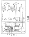
- a planar reflective mirror 51 is placed on the device reference surface 30a of the base unit 30, as shown in Fig.28.
- the device reference surface 30a is adjusted for tilt so that, when the reflected light of the light beam from the first laser light source 39 by the reflective mirror 51 is incident on the first CCD 32, the light beam projected on the first monitor 33 will be at the center of the image format.
- the device reference surface 31a of the holding unit 31 is rendered parallel to the device reference surface 30a of the base unit 30.
- a step st5 the position of a second CCD 49 is adjusted using a second laser light source 44 and a second monitor 50.
- the reference surface 1b of the outer rim 1a of the first lens 1 needs to be abutted accurately against the device reference surface 30a of the base unit 30.
- the reason is that, if dust and dirt, for example, are interposed between these reference surfaces 1b and 30a, the lenses 1 and 2 undergo tilting relative to each other, after assembling, thus worsening the optical performance, such as aberration.
- the parallelism between the reference surface 1b of the first lens 1 and the device reference surface 30a it is necessary for the parallelism between the reference surface 1b of the first lens 1 and the device reference surface 30a to be able to be observed.
- a cut-out is provided in the device reference surface 30a, as shown in Fig.24B, so that, as this device reference surface 30a is maintained, the light reflected on the reference surface 1b of the first lens 1 may be returned to the first CCD 32.
- the reflected light on this reference surface 1b may be observed, in a step st9 of Fig.25, as being a concentric diffraction pattern. If the reference surface 1b of the first lens 1 is completely in tight contact with the device reference surface 30a of the base unit 30, the concentric diffraction pattern, displayed on the first monitor 33, is at the center of the image format, because the reference surfaces 1b and 30a are completely parallel to each other.
- processing reverts to the step st8 to set the first lens 1 again or to sweep the reference surfaces 1b and 30a.
- the verticality or parallelism of the outer rim 1a of the first lens 1 and the optical axis or the device reference surface 30a of the base unit 30 may be confirmed.
- the malfunctioning state of the first lens 1 may be detected before proceeding to the next step.
- processing transfers to a step st12 of Fig.25 where it is confirmed whether or not the light reflected from the second lens 2 is incident on the center of the second CCD 49, in the same way as above. If, in a step st13, the offset of the center of the reflected light from the image center is not comprised within the reference value, processing reverts to the step st11 to mount the second lens 2 again or to sweep the device reference surface 31a.
- the parallelism between the second lens 2 and the first lens 1 is comprised within a preset range.
- the second lens 2 is caused to descend from above, in a step st14 of Fig.26, to the lens holder 3, as shown in Fig.31.
- the lens holder 3 is molded from a thermosetting resin, as described above, and has the function of suppressing the offset between the first and second lenses 1 and 2 to less than several ⁇ m. That is, the offset between the first and second lenses 1 and 2 may be removed by moving the second lens 2 along two axes perpendicular to the optical axis, so as to be positioned along the inner radius of the lens holder 3, at the same time as the second lens 2 is introduced into the lens holder 3.
- the holding unit 31 After the offset between the first and second lenses 1, 2 has been removed by the lens holder 3, the holding unit 31 is caused to descend, in a step st15 in Fig.26, to a preset position at which the second lens 2 is to be positioned ultimately. In order for the device reference surface 31a to be halted at this position, there is provided a stopper, for example. Meanwhile, the length measurement device 37 may be used to monitor whether or not the holding unit 31 has been lowered to the correct position.
- a step st16 the parallelism between the reference surface 1b and 2a of the lenses 1 and 2 is checked. If the parallelism is unsatisfactory, processing reverts to the step st18 and, if it is satisfactory, processing transfers to the next step st17.
- the second lens 2 is bonded to the lens holder 3, using a UV light curable adhesive, as the second lens 2 has been positioned to the lens holder 3 within a reference range.
- the manufacturing device With the manufacturing device according to the present invention, it can be checked, in a step st18, by observing the beam position in the second CCD 49, even after curing of the UV light curable resin, whether or not the parallelism between the first and second lenses 1 and 2 is within a reference level,.
- a lens unit is determined to be a reject if the parallelism between the two lenses 1 and 2 is not confined within a reference value.
- a step st19 when the adhesive is cured completely, the attraction of the second lens 2 with respect to the device reference surface 31a of the holding unit 31 is canceled, when the adhesive is cured completely.
- a lens assy composed of the lenses 1 and 2 and the lens holder 3 is spaced apart from the device reference surface 31a.
- the holding unit 31 is retreated towards above and an offset confirming mirror 52 is inserted to a space above the lens assy, as shown in Fig. 32.
- the laser light radiated from the first laser light source 39 is incident on and transmitted through the respective lenses 1 and 2 of the lens assy so as to be received through an offset check mirror 52 by a third CCD 53.
- the diffraction pattern, imaged by this third CCD 53, is displayed on a third monitor 54.
- a step st21 it is checked whether or not the offset between the first and second lenses 1 and 2 is comprised within a prescribed range.
- the offset of the second lens 2 relative to the first lens 1 may be detected by transmitting the laser light through the first and second lenses 1 and 2 and by remote-detecting the center position of the diffraction pattern of the transmitted light, as disclosed in Japanese Laying-Open Patent Publication H-10-255304.
- a lens unit is determined to be a reject if the parallelism between the two lenses 1 and 2 is not confined within a reference value.
- a step st22 the aberration of the objective lens unit, composed of the first and second lenses 1 and 2, is measured. With the aberration within the reference range, processing transfers to a step st23 to complete the objective lens unit. With the aberration outside the reference range, the objective lens unit is determined to be a reject.
- the objective lens unit manufacturing device is made up by a device section for introducing the second lens 2 into the lens holder 3, as shown in Fig.35, and a device section for introducing the first lens 1 into the lens holder 3, into which the second lens 2 has been introduced, as shown in Fig.38.
- the device section for introducing the second lens 2 into the lens holder 3 includes a holding unit 31 and a base unit 30, as in the case of the above-described manufacturing device, as shown in Fig.35. This device section introduces the second lens 2 in position in the lens holder 3.
- the holding unit 31 is substantially cylindrically-shaped, with an inner spacing, as in the above-described manufacturing device, and houses the second lens 2 under an air pressure differential produced across the inner and outer sides on evacuating the inner spacing by drawing air to outside through a suction through-hole 31b with the outer rim 2a of the second lens 2 abutting on the lower device reference surface 31a.
- the lower end of the holding unit 31 is kept closed at this time by the second lens 2.
- the upper end of this holding unit 31 is fitted with a glass cover 35 for hermetically sealing the inner spacing.
- the holding unit 31 is supported by a so-called cross roll bearing, that is a uni-axial movement stage 36, and is movable along the optical axis of the second lens 2.
- the amount of movement of this holding unit 31 may be detected by for example a magnetic length measurement device 37.
- the holding unit 31 is moved by a driving power source 38, such as a pneumatic cylinder, a linear motor or a stepping motor.
- the base unit 30 is substantially columnar-shaped and has its upper surface as a device reference surface 30a.
- This device reference surface 30a in the previous embodiment is shaped to receive the outer rim 1a of the first lens 1.
- the device reference surface 30a is shaped to set the lens holder 3 directly thereon.
- the absolute distances of the device reference surfaces 30a, 31a along the optical axes are detectable by the length measurement device 37.
- step st31 shown in Fig.33
- the parallelism between the device reference surface 31a of the holding unit 31 and the device reference surface 30a of the base unit 30 is adjusted accurately at the outset. If, in a step st32, the parallelism between the device reference surfaces 31a, 30a is comprised within a preset value, processing transfers to a step st33 and, if otherwise, processing reverts to the step st31.
- the lens holder 3 is set on the device reference surface 30a of the base unit 30, as shown in Fig.35.
- the outer diameter of the device reference surface 30a is set so as to be equal to the outer diameter of the first lens 1, with the step 3a as the reference surface of the lens holder 3 abutting against the device reference surface 30a.
- a step st34 shown in Fig.33
- the reference surface 2b of the second lens 2 is abutted against the device reference surface 31a of the holding unit 31, and air within this holding unit 31 is drawn by suction to attract the second lens 2 to the holding unit 31.
- a step st35 shown in Fig.33, it is monitored whether or not the parallelism between the reference surface 2b of the second lens 2 and the device reference surface 31a of the holding unit 31 is kept, using the laser light. If this parallelism is within a prescribed range, processing transfers to a step st36 and, if otherwise, processing reverts to the step st34 for renewed setting or sweeping the reference surfaces 2b and 31a. The above sequence of operations is repeated until the predetermined parallelism is reached.
- a step st36 the holding unit 31 is lowered towards the lens holder 3.
- the holding unit 31 is halted when the device reference surface 31a of the holding unit 31 is at a predetermined distance from the device reference surface 30a of the base unit 30, as shown in Fig.36.
- the position relationships between the second lens 2 and the lens holder 3 are selected such that the surface of the second lens 2 towards the optical recording medium and the surface of the protector 6 of the lens holder 3 will be spaced apart by a predetermined distance, as shown in Fig.37.
- the distance between the surface of the second lens 2 towards the optical recording medium and the surface of the protector 6 can be prescribed accurately by prescribing the distance from the device reference surface 30a of the base unit 30 abutted against the step 3a, shown by arrow b in Fig.37, to the surface of the second lens 2 towards the optical recording medium.
- the lens holder 3 is formed e.g., of a thermosetting resin, as described above, and is molded so that the distance from the step 3a to the end face thereof carrying the protector 6 is approximately within ⁇ 3 ⁇ m.
- the protector is formed of a protector material, such as fluorine coating material, having buffering and low friction coefficients, and is formed to a thickness precision within approximately less than tens of ⁇ m. Consequently, the precision on the order of approximately tens of ⁇ m is maintained for the distance from the step 3a to the surface of the protector 6, as shown by arrow a in Fig.37.
- the error in the distance from the device reference surface 30a to the surface of the second lens 2, as indicated by arrow b in Fig.37, is kept to approximately less than several ⁇ m by the objective lens unit manufacturing device. Consequently, the accuracy of approximately less than tens of ⁇ m may be maintained for the distance between the surface of the second lens 2 and the surface of the protector 6.
- the lens holder 3, carrying the second lens 2 is mounted on the device section for introducing the first lens 1 into the lens holder 3, as shown in Fig.38.
- This device section includes a movable base unit 59, capable of holding the first lens 1 on a device reference surface 58, by suction, and a holding unit 56, capable of holding the lens holder 3, carrying the second lens 2, by suction on a device reference surface 55.
- the device reference surface 58 as an upper surface of the movable base unit 59, is adjusted so as to be accurately perpendicular to the optical axis of the first lens 1 placed thereon.
- the movable base unit 59 is substantially cylindrically-shaped, with an inner spacing, and holds the first lens 1 under an air pressure differential produced across the inner and outer sides on evacuating the inner spacing, by drawing air therein to outside through a suction through-hole, with the outer rim 1a of the first lens 1 abutting on the device reference surface 58.
- the upper end of the movable base unit 59 is closed at this time by the first lens 1.
- the lower end of this movable base unit 59 is fitted with a glass cover 34 for hermetically sealing the inner spacing.
- the glass cover 34 is tilted relative to the device reference surface 58 towards the upper end thereof to reflect the laser light illuminated on the outer rim 1a of the first lens 1 so as not to produce the stray light.
- the movable base unit 59 is supported by a so-called cross roll bearing, that is a uni-axial movement stage 36, and is movable along the optical axes of the first and second lenses 1 and 2.
- the amount of movement of this movable base unit 59 may be detected by for example a magnetic length measurement device 37.
- the holding unit 31 is moved by a driving power source 38, such as a pneumatic cylinder, a linear motor or a stepping motor.
- the holding unit 56 is substantially cylindrically-shaped, with an inner spacing, and holds the second lens 2 under an air pressure differential produced across the inner and outer sides on evacuating the inner spacing by drawing air therein to outside through a suction through-hole, with the lens holder 3, carrying the second lens 2, abutting on the device reference surface 55.
- the lens holder 3 mounting the second lens 2 is held by the surface thereof carrying the protector 6 compressing against the device reference surface 55.
- the lower end of the holding unit 56 is closed at this time by the lens holder 3 and the second lens 2.
- the upper end of this holding unit 56 is fitted with a glass cover 35 towards its lower end for hermetically sealing the inner spacing.
- the glass cover 35 is tilted relative to the device reference surface 55 towards its upper end to reflect the laser light illuminated on the outer rim 2a of the second lens 2 so as not to produce the stray light.
- the holding unit 56 is supported by an inclined stage 57 for tilt adjustment.
- This device includes a detection system, including a first laser light source 39, for detecting the parallelism of the outer rim of the first lens, set on the device reference surface 58 of the movable base unit 59, relative to the device reference surface 58.
- a first laser light source 39 any suitable monochromatic light source, such as a gas laser or a solid laser, may be used in addition to a semiconductor laser.
- the light beam radiated from the first laser light source 39 is turned into collimated light, with an enlarged beam diameter, by a collimator lens and a beam expander 40.
- the light beam, now turned into the collimated light is transmitted through a beam splitter 41, a mirror 42 and the glass cover 34 at the lower end of the movable base unit 59 so as to fall on the upper end of the movable base unit 59. If the first lens is held on the device reference surface 59 at the upper end of the movable base unit 58, this collimated light is reflected by the reference surface 1b of the outer rim 1a of the first lens 1 and thence returned through the glass cover 34 and the mirror 42 to the beam splitter 41.
- the return light, reflected back from the is reflected back from the reference surface 1b of the outer rim 1a of the first lens 1, is reflected back from the reflecting surface of the beam splitter 41 and branched from the return optical path to the first laser light source 39 to fall through mirror 43 on the first CCD 32 operating as detection means.
- the image picked up by the first CCD 32 is displayed on the second monitor 33.
- the collimating of the light beam from the first laser light source 39 is adjusted on the imaging surface of the first CCD 32 so that the beam diameter will be minimized.
- This device includes a detection system, including a second laser light source 44, for detecting the parallelism of the outer rim of the second lens, held under suction on the device reference surface 55 of the holding unit 56, relative to the device reference surface 55.
- a detection system including a second laser light source 44, for detecting the parallelism of the outer rim of the second lens, held under suction on the device reference surface 55 of the holding unit 56, relative to the device reference surface 55.
- a detection system including a second laser light source 44, for detecting the parallelism of the outer rim of the second lens, held under suction on the device reference surface 55 of the holding unit 56, relative to the device reference surface 55.
- a detection system including a second laser light source 44, for detecting the parallelism of the outer rim of the second lens, held under suction on the device reference surface 55 of the holding unit 56, relative to the device reference surface 55.
- any suitable monochromatic light source such as a gas laser or a solid laser, may be used in addition to
- the light beam radiated from the second laser light source 44 is turned into collimated light, with an enlarged beam diameter, by a collimator lens and a beam expander 45.
- the light beam, now turned into the collimated light is transmitted through a beam splitter 46, a mirror 41 and the glass cover 35 at the upper end of the holding unit 56 so as to fall on the lower end of the holding unit 56. If the second lens 2 is held on the device reference surface 55 at the lower end of the holding unit 56, this collimated light is reflected by the reference surface of the outer rim of the second lens 2 and thence returned through the glass cover 35 and the mirror 41 to the beam splitter 46.
- the return light is reflected back from the reflecting surface of the beam splitter 46 and branched from the return optical path to the first laser light source 44 to fall through mirror 48 on the second CCD 49 operating as detection means.
- the image picked up by the second CCD 49 is displayed on the second monitor 50.
- the collimating of the light beam from the second laser light source 44 is adjusted on the imaging surface of the second CCD 49 so that the beam diameter will be minimized.
- This device includes a focusing error signals detecting optical system 60.
- this focusing error signal detecting optical system 60 is an optical system for detecting the focusing error signals by a so-called astigmatic aberration method or a differential concentric method.
- This focusing error signal detecting optical system 60 includes a semiconductor laser 61, as a light source, and collimates the light beam, radiated from the semiconductor laser 61, by a collimator lens 62, and illuminates the resulting collimated light beam through the beam splitter 63, mirror 64 and the glass cover 34 from the lower side of the movable base unit 59 into the inside of the movable base unit 59.
- the first lens 1 is set on the device reference surface 58 of the movable base unit 59, the light beam is incident on the first lens 1.
- the second lens 2 is mounted on the lens holder 3 by the holding unit 56, the light beam falls on the second lens 2.
- the collimated light beam sequentially incident on the first and second lenses 1 and 2, is focussed on a point above the second lens 2.
- the mirror 64 is reciprocable with respect to the lower portion of the movable base unit 59, and includes an aperture corresponding to the effective diameter of the objective lens unit.
- a glass cover 69 having a reflective surface, is mounted in the vicinity of the focal point of the objective lens unit, as shown in Fig.39.
- This glass cover 69 is designed to be equal in thickness and refractive index to the cover layer of the optical recording medium used in conjunction with the objective lens unit.
- the light beam, converged by the first and second lenses 1 and 2 is reflected by the reflective surface of the glass cover 69 and returned to the beam splitter 63 through the second lens 2, first lens 1, glass cover 34 and the mirror 64, as shown in Fig.38.
- This return light is reflected by the reflecting surface of the beam splitter 63, on the beam splitter 63, and branched from the return optical path to the semiconductor laser 61. If the astigmatic method is used, this return light is transmitted through the mirror 65, converging lens 66 and a cylindrical lens 67 to produce astigmatic aberration so as to be then converged on the light receiving surface of a photodetector 68.
- the light receiving surface of the photodetector 68 is divided from the center into four radial areas, outputting photodetector signals independently of one another. Focusing error signals and pull-in signals may be generated by calculations based on the four photodetector signals, output from the photodetector 68, as will be explained subsequently.
- the glass cover 69 is supported by being secured to the movable part of the voice coil motor as driving means actuatable in the optical axis direction as shown in Fig.39.
- This voice coil motor has a leaf spring 70.
- the glass cover 69 and the coil 72 are carried by this leaf spring 70 so that the glass cover 69 and the coil 72 are movable as movable parts.
- the voice coil moto is a fixed part and includes a magnet 71 in the vicinity of the coil 72.
- the glass cover 69 is moved along the direction of the optical axis, under the interaction of the current supplied to the coil 72 and the magnetic field generated by the magnet 71, by the driving current supplied to the coil 72.
- the leaf spring 70 of the voice coil motor includes a through-hole 73 for transmission smaller in diameter than the second lens 2, in order for the laser light radiated from the second laser light source 44 to be illuminated on the surface of the second lens 2 proximate to the optical recording medium, as shown for example in Figs.39 and 40.
- the parallelism of the surface of the second lens 2 close to the optical recording medium to the device reference surface 58 of the movable base unit 59 can be monitored through this through-hole 73.
- a step st39 shown in Fig.34, the parallelism between the device reference surface 58 of the movable base unit 59, used for positioning the first lens 1, and the surface of the second lens 2, mounted to the lens holder 3, held by the holding unit 56, which surface is closer to the optical recording medium, is adjusted. If the parallelism between the surface of the second lens 2 and the device reference surface 58 of the movable base unit 59 is not comprised within the preset range, the inclined stage 57 is adjusted so that the parallelism between the surface of the second lens 2 and the device reference surface 58 of the movable base unit 59 will be comprised within the preset range.
- a step st40 the parallelism between the device reference surface 58 and the surface of the second lens 2 is checked and, if the parallelism is within the prescribed range, processing transfers to a step st41. If otherwise, processing reverts to a step st39.
- the first lens 1 is mounted on the device reference surface 58 of the movable base unit 59, as shown in Fig.38.
- a step st42 shown in Fig.34, the laser light from the first laser light source 39, reflected by the reference surface 1b of the first lens 1, is checked to verify the parallelism between the reference surface 1b of the first lens 1 and the device reference surface 58 of the movable base unit 59.
- the mirror 64 of the focusing error signal detecting optical system 60 is receded back from the position below the movable base unit 59.
- processing transfers to a step st44. If the parallelism is not within the prescribed range, processing reverts to a step st41 for re-setting, or the reference surfaces 1b and 58 are swept. This sequence of operations is repeated until the parallelism is within the prescribed value.
- the mirror 64 of the focusing error signal detecting optical system 60 is inserted to a position below the movable base unit 59, as shown in Fig.38.
- the spherical aberration should be zero when the distance between the two lenses of the set is equal to the design value.
- refractive curved surfaces or the thicknesses of the respective lenses possibly affecting the spherical aberration, are deviated from the design values, due to, for example, an offset from a design value of the metal die for molding, or variations in the molding conditions. It is known to adjust the distance between the two lenses to minimize the spherical aberration in the assembled state of the double lens set.
- adjustment may be made by exploiting this principle, in such a manner that, as the focusing error signals are detected, the device reference surface 58 is raised to a position where the center value of the focusing error signals is zero, in order to minimize the spherical aberration on the objective lens unit under a condition that the lenses molded using variable metal dies or under variable molding conditions co-exist.
- a step st44 shown in Fig.34 the movable base unit 59 is uplifted to introduce the first lens 1 set on the device reference surface 58 into the lens holder 3.
- the glass cover 69 is vibrated along the optical axis by the voice coil motor. That is, when the movable base unit 59 is raised, a sinusoidal driving voltage, for example, is supplied to the coil 72 of the voice coil motor to vibrate the glass cover 69 along the optical axis.
- the objective lens unit is vibrated along the optical axis by an objective lens unit driving actuator to detect the so-called focusing error signals (S-shaped signal) and a sum signal to be incident on a detector (pull-in signal) to set the application timing of focusing servo.
- the objective lens unit is fixed, instead of vibrating the objective lens unit by the objective lens unit driving actuator, with the glass cover 69 being forced into vibrations. At this time, the focusing error signals and the pull-in signals are detected, as shown in Figs.41A to 41C.
- the signal levels of the focusing error signals in the case of, for example, an astigmatic method are defined by [A+C-(B+D)], while the pull-in level is defined by [A+C+B+D)].
- the relationship between the S-shaped waveform of the focusing error signals and the spherical aberration of the objective lens unit is hereinafter explained.
- the S-shaped waveform of the focusing error signals With the zero spherical aberration, the S-shaped waveform of the focusing error signals becomes symmetrical in the up-and-down, with the focusing error signals becoming zero V for the maximum pull-in level.
- the spherical aberration is of a negative polarity, the S-shaped waveform of the focusing error signals becomes asymmetrical in the up-and-down direction, with the focusing error signals being of negative polarity at the maximum pull-in level, as shown in Fig.41A .
- the S-shaped waveform of the focusing error signals becomes asymmetrical in the up-and-down, with the focusing error signals becoming of a positive polarity for the maximum pull-in level, as shown in Fig.41C.
- the state of the focusing error signal level can be estimated from the signal level of the focusing errors at the maximum point of the pull-in level.
- the state of the focusing error signal level can be estimated by detecting the level of the center value of the S-shaped signal of the focusing error signals.
- V center (Vt + Vb)/2 where Vt and Vb are a top voltage and a bottom voltage of the S-shaped signal of the focusing error signals, respectively.
- the spherical aberration of the objective lens unit is plotted against the center value (voltage) of the S-shaped signal waveform of the focusing error signals, a constant relationship is obtained, as shown in Fig.42.
- the graph shows data in which plural lenses molded using plural metal dies co-exist, with the numerical aperture (NA) of 0.85, the working wavelength ( ⁇ ) of 405 nm and with the effective diameter of 3 mm. Based on this relationship, it is possible to find a center value of the S-shaped signal for which the absolute value of the spherical aberration is minimum.
- a step st46 shown in Fig.34, the center value of the S-shaped signal of the focusing error signals is detected to check whether or not the so detected value is within a preset range with respect to a preset value. It the center value is within a prescribed value, processing transfers to a step st47 and, if otherwise, processing reverts to a step st44 to repeat the processing of adjusting the position of the first lens 1.
- a step st47 the first lens 1 is bonded to the lens holder 3.
- the objective lens unit is completed on curing the adhesive in a step st48.
- the objective lens unit assembled using the device and the method according to the present invention, is used for an optical pickup device.
- the objective lens unit may be mounted to the objective lens driving mechanism used for a conventional optical pickup device as shown in Figs.43 and 44.
- the objective lens unit driving mechanism on which is loaded the objective lens unit of the present invention, such a mechanism similar to the conventional mechanism may be used.
- a coil bobbin 8 carrying the objective lens
- a dumper material 11 is provided on the proximal sides of the wires 9 carried by the base block 10.
- a focusing coil 12 and a tracking coil 13 are mounted on the coil bobbin 8.
- On the base block 10 are mounted a magnet 14 and a yoke 15. The magnet 14 and the yoke 15 are arranged so that the focusing col 12 and the tracking coil 13 are placed in the magnetic field thereby produced.
- the objective lens unit driving mechanism causes movement of a coil bobbin 8 along the focusing direction parallel to the optical axis of the objective lens unit, under the interaction of the driving current and the magnetic field formed by the magnet 14 and the yoke 15. Moreover, when the driving current is supplied to the tracking coil 13, the objective lens unit driving mechanism causes movement of the coil bobbin 8 along the planar tracking direction perpendicular to the optical axis of the objective lens unit.
- the optical pickup device controls the driving currents supplied to the focusing col 12 and the tracking coil 13 to cause movement of the objective lens unit to control the position of the objective lens unit in such a manner that the light spot of the light beam converged by this objective lens unit will be formed at all times on the signal recording surface of the optical recording medium to follow the recording track formed on the optical recording medium.
- the up-and-down direction in Fig.43 and the depth-wise direction in Fig.44 correspond to the radial direction of the optical disc, while the left and right direction in Figs.43 and 44 correspond to the tangential direction thereof.
- the optical pickup device having the objective lens unit driving mechanism and the objective lens unit according to the present invention, includes a semiconductor laser (LD) 16, operating as a light source, as shown in Fig.45.
- a linear-polarized light beam L1 radiated as a divergent light beam from the semiconductor laser 16, is collimated by a collimator lens 17 and has its optical path bent by 90° by the mirror 18 to fall on a polarizing beam splitter (PBS) 19.
- PBS polarizing beam splitter
- the light beam transmitted through the polarizing beam splitter 19 is turned into circular polarized light by a ⁇ /4 plate (quarter wave plate) 20 to fall on a beam expander 21 composed of a concave mirror and a convex lens so as to be thereby expanded in beam diameter to fall on an objective lens unit 51.
- This objective lens unit 51 is supported by an objective lens unit driving mechanism, not shown, for movement in the focusing direction F 1 parallel to the optical axis and in a planar tracking direction T 1 perpendicular to the
- the light beam incident on the objective lens unit is converged by this objective lens unit 51 and illuminated on the signal recording surface of an optical recording medium 110, such as an optical disc.
- the light beam L 1 illuminated on the signal recording surface of the optical recording medium 110, is modulated in a preset manner by this signal recording surface with respect to the direction of polarization and reflected to fall on the objective lens unit 51.
- a return light beam L 2 is transmitted through a beam expander 21 and turned by the ⁇ /4 plate (quarter wave plate) 20 into linear polarized light of the direction of polarization perpendicular to the direction of polarization of the light beam L 1 incident on the optical recording medium 110.
- the resulting linear polarized light is returned to the polarizing beam splitter 19.
- the return light beam L 2 is reflected by the reflecting surface within the beam splitter 19 to fall on a second polarizing beam splitter 22.
- This second polarizing beam splitter 22 is set so that, in the state in which the return light beam L 2 is not modulated by the optical recording medium 110, the amount of the transmitted light will be equal to the amount of the reflected light.
- the return light beam L 2 , transmitted through the second polarizing beam splitter 22, is converged by enlarging lens systems 23 and 24 on a first photodetector (PD1) 25.
- the return light beam L 2 , reflected by the second polarizing beam splitter 22, is converged through a converging lens system 26 and a knife edge 27 to a second photodetector (PD2) 28.
- variable signals such as RF signals, focusing error signals or tracking error signals may be generated to read out information signals recorded on the optical recording medium 110.
- the so-called astigmatic method or the so-called differential concentric method may be used in addition to the above-described knife edge method.
- the so-called push-pull method, or the so-called differential push-pull method (DPP method) may be used.
- the present optical pickup device is able not only to read out information signals from the optical recording medium but also to write information signals on the optical recording medium 110.
- a recording and/or reproducing apparatus may be constructed by providing the optical pickup device, described above, and a recording medium holding mechanism, adapted for holding and rotationally driving the optical recording medium 110, such as an optical disc, as shown in Fig.45.
- the signals read out by the optical pickup device from the optical recording medium 110 are processed by the signal processing circuit to generate RF signals and various error signals.
- the signals input to this recording and/or reproducing apparatus from outside are processed by the signal processing circuit so as to be written by the optical pickup device on the optical recording medium 110.
- a lens is positioned in a cylindrically-shaped lens holder of a synthetic resin material, using another lens, already mounted and secured to the lens holder, as a reference, and the one lens is secured to the lens holder, for setting relative positions of the one and the other lenses, so that a double lens set comprised of two lenses, with a numerical aperture (NA) not less than 0.7, may be assembled efficiently within a short time. Since only the necessary minimum precision may be required of the lens holder, it is possible to enlarge the casting tolerance of the lens holder to improve the yield. Moreover, since the lens interval along the optical axis of the objective lens unit and the parallelism between the lenses are maintained by the precision of the objective lens unit manufacturing device, it is possible to improve the assembling reproducibility and the yield.
- an objective lens unit with a numerical aperture not less than 0.7, made up by plural lenses, in which the relative positions between the lenses may be adjusted to high accuracy and in which the spherical aberration may be reduced
Landscapes
- Physics & Mathematics (AREA)
- Optics & Photonics (AREA)
- General Physics & Mathematics (AREA)
- Optical Head (AREA)
- Lenses (AREA)
- Lens Barrels (AREA)
- Automatic Focus Adjustment (AREA)
- Moving Of The Head For Recording And Reproducing By Optical Means (AREA)
- Length Measuring Devices By Optical Means (AREA)
Applications Claiming Priority (3)
| Application Number | Priority Date | Filing Date | Title |
|---|---|---|---|
| JP2001260394 | 2001-08-29 | ||
| JP2001260394A JP2003066300A (ja) | 2001-08-29 | 2001-08-29 | 対物レンズ製造装置及び対物レンズ製造方法 |
| PCT/JP2002/008748 WO2003019547A1 (fr) | 2001-08-29 | 2002-08-29 | Dispositif de production de lentille-objet et son procede de production |
Publications (3)
| Publication Number | Publication Date |
|---|---|
| EP1426938A1 true EP1426938A1 (de) | 2004-06-09 |
| EP1426938A4 EP1426938A4 (de) | 2005-08-10 |
| EP1426938B1 EP1426938B1 (de) | 2007-01-17 |
Family
ID=19087605
Family Applications (1)
| Application Number | Title | Priority Date | Filing Date |
|---|---|---|---|
| EP02796361A Expired - Lifetime EP1426938B1 (de) | 2001-08-29 | 2002-08-29 | Vorrichtung zur herstellung einer objektivlinse und herstellungsverfahren |
Country Status (7)
| Country | Link |
|---|---|
| US (2) | US6977782B2 (de) |
| EP (1) | EP1426938B1 (de) |
| JP (1) | JP2003066300A (de) |
| KR (1) | KR20040028667A (de) |
| CN (2) | CN1478273A (de) |
| DE (1) | DE60217690T2 (de) |
| WO (1) | WO2003019547A1 (de) |
Cited By (1)
| Publication number | Priority date | Publication date | Assignee | Title |
|---|---|---|---|---|
| EP1906397A1 (de) * | 2006-09-26 | 2008-04-02 | Funai Electric Co., Ltd. | Objektivlinsenbetätigungsglied und optische Aufnahmevorrichtung damit |
Families Citing this family (44)
| Publication number | Priority date | Publication date | Assignee | Title |
|---|---|---|---|---|
| US7187630B2 (en) * | 2001-06-11 | 2007-03-06 | Mitutoyo Corporation | Focusing servo device and focusing servo method |
| KR100878530B1 (ko) * | 2002-07-29 | 2009-01-13 | 삼성전자주식회사 | 디스크 흠집을 방지하기 위한 제어 방법 및 그 장치 |
| JP3834816B2 (ja) * | 2003-04-24 | 2006-10-18 | 船井電機株式会社 | 対物レンズユニット |
| DE102004010958A1 (de) * | 2004-03-03 | 2005-09-22 | Robert Bosch Gmbh | Vorrichtung zur Herstellung einer Kamera |
| KR100612014B1 (ko) * | 2004-06-29 | 2006-08-11 | 삼성전자주식회사 | 광픽업 및 렌즈 조립 장치 및 방법 |
| JP2006048875A (ja) * | 2004-08-09 | 2006-02-16 | Victor Co Of Japan Ltd | 光情報記録再生装置 |
| JP4671097B2 (ja) * | 2004-08-27 | 2011-04-13 | ソニー株式会社 | レンズ鏡筒および撮像装置 |
| JP3766835B2 (ja) * | 2004-09-10 | 2006-04-19 | シャープ株式会社 | レンズ系調整装置およびそれを用いたレンズ系調整方法 |
| JP2006085837A (ja) | 2004-09-16 | 2006-03-30 | Konica Minolta Opto Inc | 対物レンズユニット及びこれを用いた光ピックアップ装置 |
| KR100661183B1 (ko) * | 2004-12-22 | 2006-12-26 | 삼성전자주식회사 | 수차보정기구를 가지는 광픽업 엑추에이터 및 그 조립방법 |
| CN1302296C (zh) * | 2005-03-10 | 2007-02-28 | 今湛光学科技股份有限公司 | 可精准对位于影像撷取镜头的镜片 |
| CN101218638A (zh) * | 2005-07-04 | 2008-07-09 | 皇家飞利浦电子股份有限公司 | 光学拾取和/或记录设备 |
| US20070033602A1 (en) * | 2005-08-03 | 2007-02-08 | Matsushita Electric Industrial Co., Ltd. | Disk Unit |
| US7570547B2 (en) * | 2005-08-22 | 2009-08-04 | Konica Minolta Opto, Inc. | Objective lens unit and optical pickup device |
| JP4738949B2 (ja) * | 2005-09-15 | 2011-08-03 | 富士フイルム株式会社 | 光波干渉装置 |
| US7946706B2 (en) * | 2006-02-10 | 2011-05-24 | Volk Optical Inc. | Lens assembly for vitreoretinal surgery |
| JP2008059661A (ja) * | 2006-08-30 | 2008-03-13 | Funai Electric Co Ltd | 光ピックアップ装置、および光ディスク読み取り装置 |
| CN100582845C (zh) * | 2006-12-15 | 2010-01-20 | 鸿富锦精密工业(深圳)有限公司 | 镜头模组组装装置及组装方法 |
| JP2008176887A (ja) * | 2007-01-22 | 2008-07-31 | Funai Electric Co Ltd | 対物レンズアクチュエータ及びそれを備えた光ピックアップ装置 |
| JP2009223946A (ja) * | 2008-03-17 | 2009-10-01 | Sanyo Electric Co Ltd | 光ピックアップ装置 |
| JP2009238344A (ja) * | 2008-03-28 | 2009-10-15 | Sanyo Electric Co Ltd | 光ピックアップ装置 |
| JP2009238345A (ja) * | 2008-03-28 | 2009-10-15 | Sanyo Electric Co Ltd | 光ピックアップ装置 |
| CN101983348B (zh) * | 2008-04-09 | 2014-07-02 | 日立麦克赛尔株式会社 | 透镜单元、摄像机组件及透镜单元的生产方法 |
| JP5295875B2 (ja) | 2008-11-06 | 2013-09-18 | シャープ株式会社 | カメラモジュールおよびそれを備えた電子機器、並びにカメラモジュールのレンズ位置決め方法 |
| CN101750205B (zh) * | 2008-12-10 | 2012-05-30 | 鸿富锦精密工业(深圳)有限公司 | 镜片偏心检测装置 |
| WO2010100915A1 (ja) * | 2009-03-06 | 2010-09-10 | パナソニック株式会社 | 測距装置及びその製造方法 |
| DE102009055225B4 (de) * | 2009-12-23 | 2013-09-19 | Osram Gmbh | Verfahren zur Herstellung einer Laservorrichtung |
| JP2011150755A (ja) * | 2010-01-22 | 2011-08-04 | Sanyo Electric Co Ltd | 光ピックアップ装置及びその製造方法 |
| CN102236142A (zh) * | 2010-04-28 | 2011-11-09 | 鸿富锦精密工业(深圳)有限公司 | 吸嘴 |
| WO2012041348A1 (de) * | 2010-09-30 | 2012-04-05 | Wavelight Gmbh | Herstellungsverfahren für eine schnittstelleneinheit und eine gruppe solcher schnittstelleneinheiten |
| US8717547B2 (en) | 2010-09-30 | 2014-05-06 | Alcon Research, Ltd | Production process for an interface unit and a group of such interface units |
| US9047883B2 (en) * | 2011-09-30 | 2015-06-02 | Panasonic Intellectual Property Management Co., Ltd. | Optical pickup device, optical information device, and information processing device |
| JP2014077904A (ja) * | 2012-10-11 | 2014-05-01 | Olympus Corp | 光学組立体の製造方法および組立用レンズの設計方法 |
| US10803269B2 (en) * | 2015-10-30 | 2020-10-13 | Symbol Technologies, Llc | Scan module and reader for, and method of, electro-optically reading a target by adjusting reading parameters based on target distance |
| CN107295222B (zh) * | 2016-04-13 | 2021-02-02 | 台湾东电化股份有限公司 | 照相镜头模块 |
| CN108803069A (zh) * | 2017-05-02 | 2018-11-13 | 颢天光电股份有限公司 | 装配装置及其方法 |
| CN108803071A (zh) * | 2017-05-02 | 2018-11-13 | 颢天光电股份有限公司 | 装配装置及其方法 |
| CN108803070A (zh) * | 2017-05-02 | 2018-11-13 | 颢天光电股份有限公司 | 装配装置及其方法 |
| US11681142B2 (en) * | 2018-05-14 | 2023-06-20 | Sharp Kabushiki Kaisha | Two-lens optical system, beam combining module, projector, and method for assembling two-lens optical system |
| CN112166358B (zh) * | 2018-05-30 | 2022-07-26 | 宁波舜宇光电信息有限公司 | 光学镜头、摄像模组及其组装方法 |
| JP2020020994A (ja) * | 2018-08-02 | 2020-02-06 | 浜松ホトニクス株式会社 | 固浸レンズユニット、半導体検査装置 |
| KR102669874B1 (ko) | 2021-11-23 | 2024-05-28 | 김현배 | 대형렌즈 제조용 금형장치 |
| US11994691B1 (en) * | 2022-03-30 | 2024-05-28 | Lockheed Martin Corporation | Lens installation system, lens mount and method for opto-mechanical lens mounting for high-G survivability |
| CN116047785B (zh) * | 2023-02-17 | 2024-08-30 | 西安应用光学研究所 | 一种抛物面反射镜光轴精密标定装置及标定方法 |
Citations (5)
| Publication number | Priority date | Publication date | Assignee | Title |
|---|---|---|---|---|
| JPH10255304A (ja) * | 1997-03-06 | 1998-09-25 | Sony Corp | 光学ピックアップ用対物レンズの調整方法及び調整装置 |
| US6115347A (en) * | 1996-02-12 | 2000-09-05 | Sony Corporation | Optical pick-up device, optical recording/reproducing apparatus and objective lens |
| DE10015953A1 (de) * | 1999-03-31 | 2000-10-26 | Sony Corp | Linsenhalter, Verfahren zur Herstellung eines Linsenhalters, Metallstempel für die Herstellung eines Linsenhalters und Objektivlinsenvorrichtung |
| US6256287B1 (en) * | 1998-04-17 | 2001-07-03 | U.S. Philips Corporation | Method of manufacturing a lens system comprising two lens elements |
| EP1406105A1 (de) * | 2001-07-09 | 2004-04-07 | Sony Corporation | Objektivlinse und optische erfassungseinrichtung mit der objektivlinse |
Family Cites Families (6)
| Publication number | Priority date | Publication date | Assignee | Title |
|---|---|---|---|---|
| US5021651A (en) * | 1989-05-22 | 1991-06-04 | Alps Electric Co., Ltd. | Mounting for a ball lens on a bar code reader wand having a tapered lens bore |
| JPH0721868B2 (ja) * | 1989-08-04 | 1995-03-08 | キヤノン株式会社 | 光情報処理装置 |
| JP2001184672A (ja) * | 1999-12-27 | 2001-07-06 | Matsushita Electric Ind Co Ltd | 光ディスク装置およびそのトラックホールド制御方法 |
| JP2003529107A (ja) * | 2000-03-27 | 2003-09-30 | コーニンクレッカ フィリップス エレクトロニクス エヌ ヴィ | 2個の1/2より大きい半球球面レンズを有する光学レンズ系 |
| KR100442905B1 (ko) * | 2000-10-17 | 2004-08-02 | 마쯔시다덴기산교 가부시키가이샤 | 대물 렌즈 조립체, 대물 렌즈 조립체를 조립/조정하는 장치, 광학 헤드 및 광학 기록 재생 장치 |
| EP1386316A1 (de) * | 2001-04-25 | 2004-02-04 | Koninklijke Philips Electronics N.V. | Optisches linsensystem mit mindestens einer kunststofflinse |
-
2001
- 2001-08-29 JP JP2001260394A patent/JP2003066300A/ja not_active Withdrawn
-
2002
- 2002-08-29 EP EP02796361A patent/EP1426938B1/de not_active Expired - Lifetime
- 2002-08-29 WO PCT/JP2002/008748 patent/WO2003019547A1/ja active IP Right Grant
- 2002-08-29 KR KR10-2003-7005774A patent/KR20040028667A/ko not_active Application Discontinuation
- 2002-08-29 US US10/399,867 patent/US6977782B2/en not_active Expired - Fee Related
- 2002-08-29 DE DE60217690T patent/DE60217690T2/de not_active Expired - Fee Related
- 2002-08-29 CN CNA028032357A patent/CN1478273A/zh active Pending
- 2002-08-29 CN CNB2005100590508A patent/CN1327262C/zh not_active Expired - Fee Related
-
2005
- 2005-05-11 US US11/126,168 patent/US20050201221A1/en not_active Abandoned
Patent Citations (5)
| Publication number | Priority date | Publication date | Assignee | Title |
|---|---|---|---|---|
| US6115347A (en) * | 1996-02-12 | 2000-09-05 | Sony Corporation | Optical pick-up device, optical recording/reproducing apparatus and objective lens |
| JPH10255304A (ja) * | 1997-03-06 | 1998-09-25 | Sony Corp | 光学ピックアップ用対物レンズの調整方法及び調整装置 |
| US6256287B1 (en) * | 1998-04-17 | 2001-07-03 | U.S. Philips Corporation | Method of manufacturing a lens system comprising two lens elements |
| DE10015953A1 (de) * | 1999-03-31 | 2000-10-26 | Sony Corp | Linsenhalter, Verfahren zur Herstellung eines Linsenhalters, Metallstempel für die Herstellung eines Linsenhalters und Objektivlinsenvorrichtung |
| EP1406105A1 (de) * | 2001-07-09 | 2004-04-07 | Sony Corporation | Objektivlinse und optische erfassungseinrichtung mit der objektivlinse |
Non-Patent Citations (2)
| Title |
|---|
| PATENT ABSTRACTS OF JAPAN vol. 1998, no. 14, 31 December 1998 (1998-12-31) & JP 10 255304 A (SONY CORP), 25 September 1998 (1998-09-25) * |
| See also references of WO03019547A1 * |
Cited By (2)
| Publication number | Priority date | Publication date | Assignee | Title |
|---|---|---|---|---|
| EP1906397A1 (de) * | 2006-09-26 | 2008-04-02 | Funai Electric Co., Ltd. | Objektivlinsenbetätigungsglied und optische Aufnahmevorrichtung damit |
| US7515364B2 (en) | 2006-09-26 | 2009-04-07 | Funai Electric Co., Ltd. | Objective lens actuator and optical pickup device having the same |
Also Published As
| Publication number | Publication date |
|---|---|
| US20040021951A1 (en) | 2004-02-05 |
| US20050201221A1 (en) | 2005-09-15 |
| CN1327262C (zh) | 2007-07-18 |
| EP1426938A4 (de) | 2005-08-10 |
| DE60217690T2 (de) | 2007-10-31 |
| WO2003019547A1 (fr) | 2003-03-06 |
| DE60217690D1 (de) | 2007-03-08 |
| US6977782B2 (en) | 2005-12-20 |
| CN1478273A (zh) | 2004-02-25 |
| EP1426938B1 (de) | 2007-01-17 |
| CN1673794A (zh) | 2005-09-28 |
| JP2003066300A (ja) | 2003-03-05 |
| KR20040028667A (ko) | 2004-04-03 |
Similar Documents
| Publication | Publication Date | Title |
|---|---|---|
| EP1426938B1 (de) | Vorrichtung zur herstellung einer objektivlinse und herstellungsverfahren | |
| US6549346B2 (en) | Assembled lens, optical head and optical recordable player with them | |
| US7170693B2 (en) | Objective lens, and optical pickup device using the objective lens | |
| JP3556575B2 (ja) | 対物レンズ、それを備えた光ピックアップ装置および対物レンズの組立方法 | |
| KR20000069317A (ko) | 주 렌즈와 보조 렌즈를 갖는 광학 주사 유니트 | |
| US20080253002A1 (en) | Object lens unit and optical pickup device employing the unit | |
| CN102034497A (zh) | 可变形反射镜装置以及信号处理设备 | |
| US6134195A (en) | Optical pickup device | |
| CN101042901B (zh) | 光学头、光学信息记录/再现装置及其应用设备 | |
| US20060018359A1 (en) | Structure for optical axis adjustment of laser diode and optical pickup apparatus | |
| US6266315B1 (en) | Catadioptric optical system, optical pickup and optical disk drive employing the same, and optical disk | |
| US6404710B1 (en) | Position controller and position control method of optical system and recording/reproducing apparatus and driving method thereof | |
| US6829210B2 (en) | Optical head and optical pickup | |
| US5828453A (en) | Lens designing method and objective lens apparatus with two lenses | |
| US7979872B2 (en) | Lens actuator, optical pickup device, and optical recording and reproducing apparatus | |
| JP2003067965A (ja) | 対物レンズ、光学ピックアップ装置及び記録再生装置 | |
| US7414926B2 (en) | Optical head device that prevents the displacement of the optical axis caused by expansion or contraction due to temperature change | |
| JP2003085808A (ja) | 光学素子、光ピックアップ装置及び光学素子の製造方法 | |
| JP2003021773A (ja) | 対物レンズ、光学ピックアップ装置及び記録再生装置 | |
| US20080192615A1 (en) | Actuator for an Optical Scanning Device | |
| JPH08263848A (ja) | 対物レンズの傾き調整機構 | |
| JPH10256596A (ja) | 光ピックアップ装置の光軸調整方法 | |
| JPH10308029A (ja) | ガルバノミラーを含む集積光学装置およびこれを用いた光ディスク装置 | |
| JP2004126619A (ja) | 対物レンズ、およびそれを備えた光ピックアップ装置 | |
| US20020036974A1 (en) | Optical lens, optical pickup apparatus, and optical disk apparatus using the same |
Legal Events
| Date | Code | Title | Description |
|---|---|---|---|
| PUAI | Public reference made under article 153(3) epc to a published international application that has entered the european phase |
Free format text: ORIGINAL CODE: 0009012 |
|
| 17P | Request for examination filed |
Effective date: 20030428 |
|
| AK | Designated contracting states |
Kind code of ref document: A1 Designated state(s): AT BE BG CH CY CZ DE DK EE ES FI FR GB GR IE IT LI LU MC NL PT SE TR |
|
| AX | Request for extension of the european patent |
Extension state: AL LT LV MK RO SI |
|
| RIC1 | Information provided on ipc code assigned before grant |
Ipc: 7G 02B 7/02 B Ipc: 7G 11B 7/22 B Ipc: 7G 11B 7/135 A |
|
| A4 | Supplementary search report drawn up and despatched |
Effective date: 20050623 |
|
| GRAP | Despatch of communication of intention to grant a patent |
Free format text: ORIGINAL CODE: EPIDOSNIGR1 |
|
| GRAS | Grant fee paid |
Free format text: ORIGINAL CODE: EPIDOSNIGR3 |
|
| GRAA | (expected) grant |
Free format text: ORIGINAL CODE: 0009210 |
|
| AK | Designated contracting states |
Kind code of ref document: B1 Designated state(s): DE FR GB |
|
| REG | Reference to a national code |
Ref country code: GB Ref legal event code: FG4D |
|
| REF | Corresponds to: |
Ref document number: 60217690 Country of ref document: DE Date of ref document: 20070308 Kind code of ref document: P |
|
| ET | Fr: translation filed | ||
| PGFP | Annual fee paid to national office [announced via postgrant information from national office to epo] |
Ref country code: DE Payment date: 20070823 Year of fee payment: 6 |
|
| PLBE | No opposition filed within time limit |
Free format text: ORIGINAL CODE: 0009261 |
|
| STAA | Information on the status of an ep patent application or granted ep patent |
Free format text: STATUS: NO OPPOSITION FILED WITHIN TIME LIMIT |
|
| 26N | No opposition filed |
Effective date: 20071018 |
|
| PGFP | Annual fee paid to national office [announced via postgrant information from national office to epo] |
Ref country code: GB Payment date: 20070829 Year of fee payment: 6 |
|
| PGFP | Annual fee paid to national office [announced via postgrant information from national office to epo] |
Ref country code: FR Payment date: 20070808 Year of fee payment: 6 |
|
| GBPC | Gb: european patent ceased through non-payment of renewal fee |
Effective date: 20080829 |
|
| REG | Reference to a national code |
Ref country code: FR Ref legal event code: ST Effective date: 20090430 |
|
| PG25 | Lapsed in a contracting state [announced via postgrant information from national office to epo] |
Ref country code: FR Free format text: LAPSE BECAUSE OF NON-PAYMENT OF DUE FEES Effective date: 20080901 Ref country code: DE Free format text: LAPSE BECAUSE OF NON-PAYMENT OF DUE FEES Effective date: 20090303 |
|
| PG25 | Lapsed in a contracting state [announced via postgrant information from national office to epo] |
Ref country code: GB Free format text: LAPSE BECAUSE OF NON-PAYMENT OF DUE FEES Effective date: 20080829 |