EP1422735A2 - Verfahren zur Herstellung eines gehäuses für ein elektrisches Schaltgerät - Google Patents
Verfahren zur Herstellung eines gehäuses für ein elektrisches Schaltgerät Download PDFInfo
- Publication number
- EP1422735A2 EP1422735A2 EP03024725A EP03024725A EP1422735A2 EP 1422735 A2 EP1422735 A2 EP 1422735A2 EP 03024725 A EP03024725 A EP 03024725A EP 03024725 A EP03024725 A EP 03024725A EP 1422735 A2 EP1422735 A2 EP 1422735A2
- Authority
- EP
- European Patent Office
- Prior art keywords
- housing
- thermoplastic
- shell
- laser
- housing according
- Prior art date
- Legal status (The legal status is an assumption and is not a legal conclusion. Google has not performed a legal analysis and makes no representation as to the accuracy of the status listed.)
- Withdrawn
Links
Images


Classifications
-
- H—ELECTRICITY
- H01—ELECTRIC ELEMENTS
- H01H—ELECTRIC SWITCHES; RELAYS; SELECTORS; EMERGENCY PROTECTIVE DEVICES
- H01H9/00—Details of switching devices, not covered by groups H01H1/00 - H01H7/00
-
- H—ELECTRICITY
- H01—ELECTRIC ELEMENTS
- H01H—ELECTRIC SWITCHES; RELAYS; SELECTORS; EMERGENCY PROTECTIVE DEVICES
- H01H71/00—Details of the protective switches or relays covered by groups H01H73/00 - H01H83/00
- H01H71/02—Housings; Casings; Bases; Mountings
- H01H71/025—Constructional details of housings or casings not concerning the mounting or assembly of the different internal parts
-
- B—PERFORMING OPERATIONS; TRANSPORTING
- B29—WORKING OF PLASTICS; WORKING OF SUBSTANCES IN A PLASTIC STATE IN GENERAL
- B29C—SHAPING OR JOINING OF PLASTICS; SHAPING OF MATERIAL IN A PLASTIC STATE, NOT OTHERWISE PROVIDED FOR; AFTER-TREATMENT OF THE SHAPED PRODUCTS, e.g. REPAIRING
- B29C45/00—Injection moulding, i.e. forcing the required volume of moulding material through a nozzle into a closed mould; Apparatus therefor
- B29C45/16—Making multilayered or multicoloured articles
-
- B—PERFORMING OPERATIONS; TRANSPORTING
- B29—WORKING OF PLASTICS; WORKING OF SUBSTANCES IN A PLASTIC STATE IN GENERAL
- B29C—SHAPING OR JOINING OF PLASTICS; SHAPING OF MATERIAL IN A PLASTIC STATE, NOT OTHERWISE PROVIDED FOR; AFTER-TREATMENT OF THE SHAPED PRODUCTS, e.g. REPAIRING
- B29C65/00—Joining or sealing of preformed parts, e.g. welding of plastics materials; Apparatus therefor
- B29C65/02—Joining or sealing of preformed parts, e.g. welding of plastics materials; Apparatus therefor by heating, with or without pressure
- B29C65/08—Joining or sealing of preformed parts, e.g. welding of plastics materials; Apparatus therefor by heating, with or without pressure using ultrasonic vibrations
-
- B—PERFORMING OPERATIONS; TRANSPORTING
- B29—WORKING OF PLASTICS; WORKING OF SUBSTANCES IN A PLASTIC STATE IN GENERAL
- B29C—SHAPING OR JOINING OF PLASTICS; SHAPING OF MATERIAL IN A PLASTIC STATE, NOT OTHERWISE PROVIDED FOR; AFTER-TREATMENT OF THE SHAPED PRODUCTS, e.g. REPAIRING
- B29C65/00—Joining or sealing of preformed parts, e.g. welding of plastics materials; Apparatus therefor
- B29C65/02—Joining or sealing of preformed parts, e.g. welding of plastics materials; Apparatus therefor by heating, with or without pressure
- B29C65/14—Joining or sealing of preformed parts, e.g. welding of plastics materials; Apparatus therefor by heating, with or without pressure using wave energy, i.e. electromagnetic radiation, or particle radiation
- B29C65/16—Laser beams
-
- B—PERFORMING OPERATIONS; TRANSPORTING
- B29—WORKING OF PLASTICS; WORKING OF SUBSTANCES IN A PLASTIC STATE IN GENERAL
- B29C—SHAPING OR JOINING OF PLASTICS; SHAPING OF MATERIAL IN A PLASTIC STATE, NOT OTHERWISE PROVIDED FOR; AFTER-TREATMENT OF THE SHAPED PRODUCTS, e.g. REPAIRING
- B29C66/00—General aspects of processes or apparatus for joining preformed parts
- B29C66/50—General aspects of joining tubular articles; General aspects of joining long products, i.e. bars or profiled elements; General aspects of joining single elements to tubular articles, hollow articles or bars; General aspects of joining several hollow-preforms to form hollow or tubular articles
- B29C66/51—Joining tubular articles, profiled elements or bars; Joining single elements to tubular articles, hollow articles or bars; Joining several hollow-preforms to form hollow or tubular articles
- B29C66/54—Joining several hollow-preforms, e.g. half-shells, to form hollow articles, e.g. for making balls, containers; Joining several hollow-preforms, e.g. half-cylinders, to form tubular articles
-
- B—PERFORMING OPERATIONS; TRANSPORTING
- B29—WORKING OF PLASTICS; WORKING OF SUBSTANCES IN A PLASTIC STATE IN GENERAL
- B29K—INDEXING SCHEME ASSOCIATED WITH SUBCLASSES B29B, B29C OR B29D, RELATING TO MOULDING MATERIALS OR TO MATERIALS FOR MOULDS, REINFORCEMENTS, FILLERS OR PREFORMED PARTS, e.g. INSERTS
- B29K2101/00—Use of unspecified macromolecular compounds as moulding material
- B29K2101/10—Thermosetting resins
-
- B—PERFORMING OPERATIONS; TRANSPORTING
- B29—WORKING OF PLASTICS; WORKING OF SUBSTANCES IN A PLASTIC STATE IN GENERAL
- B29K—INDEXING SCHEME ASSOCIATED WITH SUBCLASSES B29B, B29C OR B29D, RELATING TO MOULDING MATERIALS OR TO MATERIALS FOR MOULDS, REINFORCEMENTS, FILLERS OR PREFORMED PARTS, e.g. INSERTS
- B29K2101/00—Use of unspecified macromolecular compounds as moulding material
- B29K2101/12—Thermoplastic materials
-
- B—PERFORMING OPERATIONS; TRANSPORTING
- B29—WORKING OF PLASTICS; WORKING OF SUBSTANCES IN A PLASTIC STATE IN GENERAL
- B29L—INDEXING SCHEME ASSOCIATED WITH SUBCLASS B29C, RELATING TO PARTICULAR ARTICLES
- B29L2031/00—Other particular articles
- B29L2031/30—Vehicles, e.g. ships or aircraft, or body parts thereof
- B29L2031/3055—Cars
- B29L2031/3061—Number plates
-
- H—ELECTRICITY
- H01—ELECTRIC ELEMENTS
- H01H—ELECTRIC SWITCHES; RELAYS; SELECTORS; EMERGENCY PROTECTIVE DEVICES
- H01H11/00—Apparatus or processes specially adapted for the manufacture of electric switches
- H01H2011/0087—Welding switch parts by use of a laser beam
-
- H—ELECTRICITY
- H01—ELECTRIC ELEMENTS
- H01H—ELECTRIC SWITCHES; RELAYS; SELECTORS; EMERGENCY PROTECTIVE DEVICES
- H01H71/00—Details of the protective switches or relays covered by groups H01H73/00 - H01H83/00
- H01H71/04—Means for indicating condition of the switching device
-
- H—ELECTRICITY
- H01—ELECTRIC ELEMENTS
- H01H—ELECTRIC SWITCHES; RELAYS; SELECTORS; EMERGENCY PROTECTIVE DEVICES
- H01H71/00—Details of the protective switches or relays covered by groups H01H73/00 - H01H83/00
- H01H71/06—Distinguishing marks, e.g. colour coding
-
- H—ELECTRICITY
- H01—ELECTRIC ELEMENTS
- H01H—ELECTRIC SWITCHES; RELAYS; SELECTORS; EMERGENCY PROTECTIVE DEVICES
- H01H9/00—Details of switching devices, not covered by groups H01H1/00 - H01H7/00
- H01H9/30—Means for extinguishing or preventing arc between current-carrying parts
- H01H9/302—Means for extinguishing or preventing arc between current-carrying parts wherein arc-extinguishing gas is evolved from stationary parts
Definitions
- the invention relates to a method for producing a housing for an electrical Switchgear and a housing that is manufactured using this method.
- Each switchgear has a housing in which individual components are inserted and is formed from two housing halves, for example by means of riveted connections or especially with motor protection switches via snap-in connections are connected.
- both housing halves each consist of only a material, either thermoplastic, e.g. PA6 or PA6.6 or from one Thermoset, such as urea or melamine.
- the object of the invention is to provide a method of the type mentioned in the introduction, with which the manufacture of a housing for an electrical switching device by Saving or eliminating components and simplifying or eliminating assembly is simplified.
- a two-component molded part has become known from DE 200 04 900 U 1, that serves as a cover frame for an electrical installation device.
- two Molding materials one of which can be metallized and the other cannot be metallized, form-fitting through a thermoplastic two-component injection molding process connected with each other.
- Thermoplastics i.e. similar materials, are connected with each other.
- the housing can then be designed in different ways: On the one hand, the housing can be made of thermoset at least in the terminal area and at least in the area of the pre-chamber and the arc quenching chamber from a thermoplastic. Since the thermoplastic releases gas under the influence of an arc, it can be used in a particularly advantageous manner in the region of the arc chamber or the pre-chamber, as a result of which separate, loosely inserted insulating material plates can be avoided. If the housing is made of thermosetting plastic in the area of the clamps, this has the advantage that deformations of the housing due to actuation of the clamping screws are also avoided due to the higher modulus of elasticity of the thermosetting plastic compared to the thermoplastic.
- Two, for example, shell-shaped housing parts for an electrical installation device are often connected to each other with riveted joints, the edges of the Housing parts lie on top of each other.
- This connection can also be simplified be that different materials in the field of housing separation are provided, as specified in particular in claims 4 or 5.
- the two housing parts are connected by laser or ultrasound Welding.
- a section is made on the edge of both housing parts Thermoplastic provided.
- thermoplastics With thermoplastics, the ultrasonic weldability is in all Given rule.
- One of these thermoplastic materials must be used for laser welding Sections should be laser transparent so that the incoming laser light reaches the parting line arrives and there melts the laser-absorbing thermoplastic, so that it may be under additionally applied pressure leads to a connection of the components.
- thermoplastic pins are attached to a housing part made of thermosetting plastic injection molded through holes in the second housing part, whether thermal or Thermoset to be caulked afterwards.
- thermosets and thermosets can be joined in several ways: mechanically by shrinkage, the thermoset part being surrounded by the thermoplastic part at the junction and the thermoplastic shrinking onto the thermoset, and vice versa, or physically chemically if flow fronts of the two materials meet. In the latter case, diffusions can occur, with molecular chains of both materials intertwining. Adhesive or cohesive forces can also lead to liability.
- Geometric design elements can be used for material combinations that are difficult to connect such as undercuts e.g. in the form of a dovetail guide be used.
- a gassing thermoplastic can preferably be introduced or injected, whereby own arc chamber plates are no longer required. It is therefore injected into the form in which the housing is manufactured in the area of the arc quenching chamber, gassing thermoplastic, whereas the rest of the area can consist of thermoset.
- FIG. 1 shows a housing 10 of an electrical installation device with two shell-shaped housing halves 11 and 12, both made of a thermoset are.
- Indentation 13, 14 is provided, into which a thermoplastic 15, 16 is made gassing material is injected; this is done by a two component spraying process achieved in which, for example, the thermoset first and then the Thermoplastic 15, 16 is injected into the mold. So that the thermoplastic 15, 16 better holds in the recesses 13, 14, the side walls 17, 18 of the recesses Taper to the inside surface of the housing halves 11-12 like a dovetail, as in Fig 1 a shown.
- FIG. 2 shows a further embodiment of an installation housing, which from the Housing parts 20 and 21 consists of a thermoset. At the free edge of the Half of the housing is an edge region 22, 23 made of thermoplastic in one Two-component injection molding molded all around, so that the two sections 22 and 23 can be welded to one another by an ultrasound process.
- FIG. 2a shows laser welding as an alternative to ultrasound. If necessary, this can are carried out such that, for example, the circumferential narrow side wall 24 a housing half is made of laser-transparent material, so that this Component from the thermoset base 21 a and the circumferential narrow side wall 24 is composed.
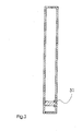
- FIG. 3 is in a housing base Installation housing made of thermosetting a pin 31 made of thermoplastic in the two-component injection molding process injected with which the opposite housing part by, for example, hot caulking.
Landscapes
- Casings For Electric Apparatus (AREA)
- Manufacture Of Switches (AREA)
- Standing Axle, Rod, Or Tube Structures Coupled By Welding, Adhesion, Or Deposition (AREA)
Abstract
Description
Zum einen kann das Gehäuse wenigstens im Klemmenbereich aus Duroplast und wenigstens im Bereich der Vorkammer und der Lichtbogenlöschkammer aus einem Thermoplast gebildet sein. Da das Thermoplast unter dem Einfluss eines Lichtbogens Gas abgibt, kann es in besonders vorteilhafter Weise im Bereich der Lichtbogenkammer bzw. der Vorkammer eingesetzt werden, wodurch eigene, lose eingelegte Isolierstoffplatten vermieden werden können. Wenn das Gehäuse im Bereich der Klemmen aus Duroplast hergestellt ist, hat dies den Vorteil, dass Verformungen des Gehäuses durch Betätigung der Klemmschrauben, aufgrund des höheren E-Moduls des Duroplastes gegenüber dem Thermoplast, ebenfalls vermieden sind.
mechanisch durch Schwindung, wobei das Duroplastteil an der Verbindungsstelle vom Thermoplastteil umgeben ist und der Thermoplast auf den Duroplast aufschwindet, und umgekehrt, oder physikalisch chemisch, wenn Fließfronten der beiden Materialien aufeinander treffen. Im letzteren Falle können Diffusionen auftreten, wobei Molekülketten beider Materialien miteinander verschlaufen. Auch Adhäsions- oder Kohäsionskräfte können zu einer Haftung führen.
Im Bereich z. B. der Lichtbogenkammer eines Leitungsschutzschalters kann bevorzugt ein gasendes Thermoplast eingebracht bzw. eingespritzt werden, wodurch eigene Lichtbogenkammerplatten nicht mehr erforderlich werden. Man spritzt daher in die Form, in der das Gehäuse hergestellt wird, im Bereich der Lichtbogenlöschkammer gasendes Thermoplast ein, wogegen der übrige Bereich aus Duroplast bestehen kann.
- Fig. 1
- eine Teilschnittansicht im Vorkammerbereich eines elektrischen Installationsgerätes,
- Fig. 1 a
- eine Teilschnittansicht im Vorkammerbereich eines elektrischen Installationsgerätes (mechanische Verbindung der Materialien),
- Fig. 2
- eine Querschnittsansicht eines Gehäuses eines elektrischen Installationsgerätes,
- Fig. 2a
- eine Querschnittsansicht eines Gehäuses eines elektrischen Installationsgerätes (Verbindungstechnik mittels Laserschweißung),
- Fig. 3
- eine weitere Teilschnittansicht eines elektrischen Installationsgehäuses.
Claims (9)
- Verfahren zur Herstellung eines aus Teilen gebildeten Gehäuses für ein elektrisches Schaltgerät, insbesondere für einen Fehlerstromschutzschalter, Leitungsschutzschalter, oder Motorschutzschalter, die nach Einbau von Schaltgerätekomponenten wie z. B. Klemmen, magnetischem und thermischem Auslöser, Schaltwerk, Lichtbogenlöschkammer und dergleichen, miteinander starr verbunden werden bzw. sind, dadurch gekennzeichnet, dass das Gehäuse wenigstens teilweise aus Thermoplast und teilweise aus Duroplast mittels eines Mehrkomponentenspritzverfahrens hergestellt wird.
- Gehäuse, hergestellt nach dem Verfahren nach Anspruch 1, dadurch gekennzeichnet, dass die Gehäuseteile wenigstens teilweise aus Duroplast hergestellt sind und insbesondere im Vorkammerbereich einen Teilbereich aus vorzugsweise gasendem Thermoplast aufweisen.
- Gehäuse nach Anspruch 2, dadurch gekennzeichnet, dass das Gehäuse einen ebenfalls im Mehrkomponentenspritzverfahren klar durchsichtigen Abschnitt zur Bildung eines aus thermoplastischen Material bestehenden Sichtfensters aufweist.
- Gehäuse nach einem der vorherigen Ansprüche, dadurch gekennzeichnet, dass das Gehäuse aus zwei Schalenhälften besteht, die aus Duroplast mit an der zur jeweils anderen Schalenhälfte zuweisenden Kante Thermoplastansätzen aufgebaut sind, so dass die Schalenhälften durch Ultraschall Schweißung miteinander verbindbar sind.
- Gehäuse nach einem der vorherigen Ansprüche, dadurch gekennzeichnet, dass das Gehäuse aus zwei Schalenhälften besteht, die aus Duroplast mit an der zur jeweils anderen Schalenhälfte zuweisenden Kante angeordneten Thermoplastansätzen aufgebaut sind, wobei genau einer dieser beiden Thermoplaste laserlichtdurchlässig, der andere laserlichtabsorbierend ist, so dass die Bauteile dadurch miteinander verbindbar sind, und dass mittels des den einen Thermoplastansatz durchdringenden Laserlichtstrahls beide Thermoplastansätze miteinander verschweißt werden.
- Gehäuse nach einem der vorigen Ansprüche, dadurch gekennzeichnet, dass an einer Schalenhälfte, die wenigstens teilweise aus Duroplast besteht, wenigstens ein Zapfen aus Thermoplast vorgesehen ist, der senkrecht von der inneren Bodenseite vorsteht und in einer daran angepassten Öffnung an der anderen Schalenhälfte einfügbar und daran bzw. darin befestigbar ist.
- Gehäuse nach Anspruch 6, dadurch gekennzeichnet, dass die Zapfen als Spreizverbinder ausgebildet sind.
- Gehäuse nach einem der vorigen Ansprüche, dadurch gekennzeichnet, dass am Gehäuse laserbeschriftbarer Thermoplast angespritzt ist.
- Gehäuse für ein auf einer Hutprofiltragschiene aufschnappbares elektrisches Installationsgerät, mit einer am Boden des Gehäuses angeordneten Ausnehmung, in die eine bewegbare Rastnase zum Aufschnappen der Gehäuse auf eine Normprofiltragschiene, insbesondere Hutprofiltragschiene, eingreift, dadurch gekennzeichnet, dass die bewegbare Nase aus Thermoplast am Gehäuse angespritzt ist.
Applications Claiming Priority (2)
| Application Number | Priority Date | Filing Date | Title |
|---|---|---|---|
| DE2002154259 DE10254259A1 (de) | 2002-11-21 | 2002-11-21 | Verfahren zur Herstellung eines Gehäuses für ein elektrisches Schaltgerät |
| DE10254259 | 2002-11-21 |
Publications (2)
| Publication Number | Publication Date |
|---|---|
| EP1422735A2 true EP1422735A2 (de) | 2004-05-26 |
| EP1422735A3 EP1422735A3 (de) | 2006-04-12 |
Family
ID=32185879
Family Applications (1)
| Application Number | Title | Priority Date | Filing Date |
|---|---|---|---|
| EP03024725A Withdrawn EP1422735A3 (de) | 2002-11-21 | 2003-10-29 | Verfahren zur Herstellung eines gehäuses für ein elektrisches Schaltgerät |
Country Status (2)
| Country | Link |
|---|---|
| EP (1) | EP1422735A3 (de) |
| DE (1) | DE10254259A1 (de) |
Cited By (5)
| Publication number | Priority date | Publication date | Assignee | Title |
|---|---|---|---|---|
| WO2007038916A1 (de) * | 2005-10-04 | 2007-04-12 | Conti Temic Microelectronic Gmbh | Verfahren zum verbinden zweier kunststoffteile |
| WO2007113184A1 (de) * | 2006-03-29 | 2007-10-11 | Siemens Aktiengesellschaft | Lichtbogen-löscheinrichtung mit lichtbogenlöschendes material für einen schutzschalter |
| US20170004934A1 (en) * | 2013-12-18 | 2017-01-05 | Siemens Aktiengesellschaft | Switching Device Having an Exchangeable Switching Piece Assembly |
| EP3189867A1 (de) * | 2016-01-06 | 2017-07-12 | Tecpharma Licensing AG | Verfahren zum herstellen von teilen und montieren von teilen an einer einspritzvorrichtung mit 2-komponentigem spritzgiessen |
| WO2023063393A1 (ja) | 2021-10-14 | 2023-04-20 | 株式会社ダイセル | 電気回路遮断装置 |
Families Citing this family (6)
| Publication number | Priority date | Publication date | Assignee | Title |
|---|---|---|---|---|
| DE102005007302A1 (de) * | 2005-02-17 | 2006-08-24 | Abb Patent Gmbh | Elektrisches Installationsgerät mit Lichtbogen-Vorkammerraum und strombegrenzender Lichtbogenlöscheinrichtung |
| DE102006042194A1 (de) | 2006-09-08 | 2008-03-27 | Panasonic Electric Works Europe Ag | Elektromagnetische Relais und Verfahren zu seiner Herstellung |
| DE102007020089A1 (de) * | 2007-04-05 | 2008-10-09 | Conti Temic Microelectronic Gmbh | Laserbearbeitbares Werkstück, Verfahren zu dessen Herstellung, sowie laserbearbeitbares Gehäuse |
| DE102008018334A1 (de) * | 2008-04-11 | 2009-10-15 | GM Global Technology Operations, Inc., Detroit | Karosseriebaugruppe für ein Kraftfahrzeug |
| DE102010026512B3 (de) * | 2010-07-08 | 2011-12-01 | Abb Ag | Installationsschaltgerät mit Gehäuse aus Thermoplast oder Duroplast sowie Verfahren zu dessen Herstellung |
| DE102011002930B4 (de) * | 2011-01-20 | 2020-09-10 | Siemens Aktiengesellschaft | Elektrischer Schalter |
Family Cites Families (18)
| Publication number | Priority date | Publication date | Assignee | Title |
|---|---|---|---|---|
| DE1987217U (de) * | 1968-06-12 | Continental Elektroindustrie Aktiengesellschaft Voigt & Haeffner, 6000 Frankfurt | Leitungsschutzschalter | |
| DE69212883T2 (de) * | 1991-04-25 | 1997-02-13 | Mitsubishi Electric Corp | Integrierend geformte gedruckte Schaltung und Verfahren zur Herstellung einer solchen |
| DE69226200T2 (de) * | 1991-11-07 | 1999-03-11 | Akbar Ringwood N.J. Ghahary | Mineralaehnliche kunststoffe |
| EP0550185B1 (de) * | 1991-12-19 | 1997-02-26 | Mitsubishi Gas Chemical Company, Inc. | Verformungsfreier gegossener Gegenstand |
| TW293130B (de) * | 1994-03-10 | 1996-12-11 | Mitsubishi Electric Corp | |
| DE19716676C2 (de) * | 1997-04-21 | 1999-02-18 | Ernst Kunststofftech Gmbh | Verfahren zum Verbinden zweier Teile |
| DE19726136A1 (de) * | 1997-06-19 | 1998-12-24 | Merck Patent Gmbh | Lasermarkierbare Kunststoffe |
| DE19731424C1 (de) * | 1997-07-22 | 1998-08-13 | Daimler Benz Ag | Verfahren zum Einbetten von metallischen Leitern mikroelektronischer Bauelemente in eine Kunststoffmasse |
| DE19751109A1 (de) * | 1997-11-18 | 1999-05-20 | Siemens Ag | Kunststoffverbundkörper sowie Verfahren und Werkstoff zum Herstellen eines Kunststoffverbundkörpers |
| DE19800828A1 (de) * | 1998-01-13 | 1999-07-15 | Ver Foerderung Inst Kunststoff | Verfahren und Vorrichtung zur Herstellung von bindenahtfreien Kunststofformteilen mit Durchbrüchen mittels Spritzprägetechnik |
| DE19806944C1 (de) * | 1998-02-19 | 1999-06-24 | Goerlitz Esg Gmbh | Selbstschalter, insbesondere Niederspannungs-Schutzschalter |
| DE19814431A1 (de) * | 1998-03-31 | 1999-10-14 | Moeller Gmbh | Elektromagnetisches Schaltgerät mit Magnetantrieb und Brückensystem |
| DE19857965A1 (de) * | 1998-12-16 | 2000-06-21 | Bayer Ag | Flammgeschützte Extrudate und mittels Preßverfahren hergestellte flammgeschützte Formkörper |
| DE19944383A1 (de) * | 1999-09-16 | 2001-04-19 | Ticona Gmbh | Gehäuse für elektrische oder elektronische Vorrichtungen mit integrierten Leiterbahnen |
| DE20004900U1 (de) * | 2000-03-17 | 2000-08-17 | Komos GmbH Komponenten Module Systeme, 07616 Bürgel | Einteiliger Abdeckrahmen für Elektroinstallationsgeräte mit teilweiser Metallisierung |
| WO2001080268A1 (en) * | 2000-04-14 | 2001-10-25 | Mitsubishi Denki Kabushiki Kaisha | Circuit breaker |
| DE10054855A1 (de) * | 2000-11-06 | 2002-05-08 | Abb Patent Gmbh | Elektrisches Installationsgerät |
| DE20204817U1 (de) * | 2002-03-26 | 2002-06-13 | Industria Lombarda Materiale Elettrico I.L.M.E. S.P.A., Mailand/Milano | Gehäusestruktur für elektrisches Material |
-
2002
- 2002-11-21 DE DE2002154259 patent/DE10254259A1/de not_active Withdrawn
-
2003
- 2003-10-29 EP EP03024725A patent/EP1422735A3/de not_active Withdrawn
Cited By (6)
| Publication number | Priority date | Publication date | Assignee | Title |
|---|---|---|---|---|
| WO2007038916A1 (de) * | 2005-10-04 | 2007-04-12 | Conti Temic Microelectronic Gmbh | Verfahren zum verbinden zweier kunststoffteile |
| WO2007113184A1 (de) * | 2006-03-29 | 2007-10-11 | Siemens Aktiengesellschaft | Lichtbogen-löscheinrichtung mit lichtbogenlöschendes material für einen schutzschalter |
| US20170004934A1 (en) * | 2013-12-18 | 2017-01-05 | Siemens Aktiengesellschaft | Switching Device Having an Exchangeable Switching Piece Assembly |
| US9922780B2 (en) * | 2013-12-18 | 2018-03-20 | Siemens Aktiengesellschaft | Switching device having an exchangeable switching piece assembly |
| EP3189867A1 (de) * | 2016-01-06 | 2017-07-12 | Tecpharma Licensing AG | Verfahren zum herstellen von teilen und montieren von teilen an einer einspritzvorrichtung mit 2-komponentigem spritzgiessen |
| WO2023063393A1 (ja) | 2021-10-14 | 2023-04-20 | 株式会社ダイセル | 電気回路遮断装置 |
Also Published As
| Publication number | Publication date |
|---|---|
| EP1422735A3 (de) | 2006-04-12 |
| DE10254259A1 (de) | 2004-06-03 |
Similar Documents
| Publication | Publication Date | Title |
|---|---|---|
| DE69019907T2 (de) | Mittel und Verfahren zum Sichern eines Einsatzstückes in einer Steckhülse. | |
| EP0633585B1 (de) | Gehäuse für Geräte der elektrischen Nachrichtentechnik | |
| EP0261307B1 (de) | Explosionsgeschütztes Modulgehäuse | |
| DE102012203459A1 (de) | Mehrpolige Steckverbindungseinheit für Dreiphasen-Wechselstromsysteme | |
| DE10254259A1 (de) | Verfahren zur Herstellung eines Gehäuses für ein elektrisches Schaltgerät | |
| WO2019238341A1 (de) | Verfahren zum herstellen einer deckelbaugruppe für ein zellgehäuse einer prismatischen batteriezelle einer hochvoltbatterie eines kraftfahrzeugs, batteriezelle sowie hochvoltbatterie | |
| DE4419023A1 (de) | Einbaustecker | |
| DE102020006274A1 (de) | Flüssigkeitsgekühlte Busbaranordnung | |
| DE4431274C2 (de) | Verfahren zum Herstellen eines Elektro-Installationsgerätes sowie Elektro-Installationsgerät | |
| EP0805619B1 (de) | Abschirm-Formteil für elektronische Bauelemente | |
| DE102014214134B4 (de) | Kunststoffbauteil eines Fahrzeuglenkrads oder eines in einem Fahrzeuglenkrad anordbaren Gassackmoduls und Verfahren zu dessen Herstellung | |
| WO2017102348A1 (de) | Energiespeichermodul | |
| DE102019216230A1 (de) | Befestigungsstruktur zwischen einer Abdeckung und einem Gehäuse und Schmelzsicherungseinheit | |
| DE102018210621A1 (de) | Elektronikmodul mit Steckeranschluss | |
| DE19813323C1 (de) | Anordnung eines thermoplastischen Schaltungsträgers mit einer elektrisch leitenden Folie sowie Verfahren zum Herstellen einer solchen Anordnung | |
| EP0800712A2 (de) | Mehrpoliger elektrischer steckverbinder | |
| DE102007023326B4 (de) | Elektrische Schalteinrichtung mit einer Lichtbogenlöscheinheit | |
| EP3996894B1 (de) | Gehäuse eines elektronikmoduls und dessen herstellung | |
| DE102005001151B4 (de) | Bauelementanordnung zur Serienschaltung bei Hochspannungsanwendungen | |
| DE102013008831B3 (de) | Batterie mit einer Mehrzahl von Batteriezellen und Verfahren zum Fertigen einer Batterie | |
| EP2685562B1 (de) | Installationsschaltgerät mit Anschlussklemmen | |
| DE10248830C1 (de) | Elektrische Einrichtung | |
| DE102008026771A1 (de) | Geschirmte elektrische Verbindungsanordnung | |
| EP1344234B1 (de) | Anschlussschiene aus profilierten halbzeugen, für elektrische geräte und apparate, für verschiedene nennströme | |
| EP1365487B1 (de) | Verfahren zur Herstellung eines Gehäuses |
Legal Events
| Date | Code | Title | Description |
|---|---|---|---|
| PUAI | Public reference made under article 153(3) epc to a published international application that has entered the european phase |
Free format text: ORIGINAL CODE: 0009012 |
|
| AK | Designated contracting states |
Kind code of ref document: A2 Designated state(s): AT BE BG CH CY CZ DE DK EE ES FI FR GB GR HU IE IT LI LU MC NL PT RO SE SI SK TR |
|
| AX | Request for extension of the european patent |
Extension state: AL LT LV MK |
|
| PUAL | Search report despatched |
Free format text: ORIGINAL CODE: 0009013 |
|
| AK | Designated contracting states |
Kind code of ref document: A3 Designated state(s): AT BE BG CH CY CZ DE DK EE ES FI FR GB GR HU IE IT LI LU MC NL PT RO SE SI SK TR |
|
| AX | Request for extension of the european patent |
Extension state: AL LT LV MK |
|
| 17P | Request for examination filed |
Effective date: 20060503 |
|
| AKX | Designation fees paid |
Designated state(s): AT BE BG CH CY CZ DE DK EE ES FI FR GB GR HU IE IT LI LU MC NL PT RO SE SI SK TR |
|
| STAA | Information on the status of an ep patent application or granted ep patent |
Free format text: STATUS: THE APPLICATION IS DEEMED TO BE WITHDRAWN |
|
| 18D | Application deemed to be withdrawn |
Effective date: 20110503 |