EP1401034A2 - Dispositif organique électroluminescent utilisant l'effet de resonance optique - Google Patents
Dispositif organique électroluminescent utilisant l'effet de resonance optique Download PDFInfo
- Publication number
- EP1401034A2 EP1401034A2 EP03255847A EP03255847A EP1401034A2 EP 1401034 A2 EP1401034 A2 EP 1401034A2 EP 03255847 A EP03255847 A EP 03255847A EP 03255847 A EP03255847 A EP 03255847A EP 1401034 A2 EP1401034 A2 EP 1401034A2
- Authority
- EP
- European Patent Office
- Prior art keywords
- layer
- transparent
- organic
- semi
- stripe pattern
- Prior art date
- Legal status (The legal status is an assumption and is not a legal conclusion. Google has not performed a legal analysis and makes no representation as to the accuracy of the status listed.)
- Ceased
Links
Images


Classifications
-
- H—ELECTRICITY
- H05—ELECTRIC TECHNIQUES NOT OTHERWISE PROVIDED FOR
- H05B—ELECTRIC HEATING; ELECTRIC LIGHT SOURCES NOT OTHERWISE PROVIDED FOR; CIRCUIT ARRANGEMENTS FOR ELECTRIC LIGHT SOURCES, IN GENERAL
- H05B33/00—Electroluminescent light sources
- H05B33/12—Light sources with substantially two-dimensional [2D] radiating surfaces
- H05B33/22—Light sources with substantially two-dimensional [2D] radiating surfaces characterised by the chemical or physical composition or the arrangement of auxiliary dielectric or reflective layers
-
- H—ELECTRICITY
- H10—SEMICONDUCTOR DEVICES; ELECTRIC SOLID-STATE DEVICES NOT OTHERWISE PROVIDED FOR
- H10K—ORGANIC ELECTRIC SOLID-STATE DEVICES
- H10K59/00—Integrated devices, or assemblies of multiple devices, comprising at least one organic light-emitting element covered by group H10K50/00
- H10K59/80—Constructional details
- H10K59/875—Arrangements for extracting light from the devices
- H10K59/876—Arrangements for extracting light from the devices comprising a resonant cavity structure, e.g. Bragg reflector pair
-
- H—ELECTRICITY
- H10—SEMICONDUCTOR DEVICES; ELECTRIC SOLID-STATE DEVICES NOT OTHERWISE PROVIDED FOR
- H10K—ORGANIC ELECTRIC SOLID-STATE DEVICES
- H10K50/00—Organic light-emitting devices
- H10K50/80—Constructional details
- H10K50/85—Arrangements for extracting light from the devices
- H10K50/852—Arrangements for extracting light from the devices comprising a resonant cavity structure, e.g. Bragg reflector pair
-
- H—ELECTRICITY
- H10—SEMICONDUCTOR DEVICES; ELECTRIC SOLID-STATE DEVICES NOT OTHERWISE PROVIDED FOR
- H10K—ORGANIC ELECTRIC SOLID-STATE DEVICES
- H10K59/00—Integrated devices, or assemblies of multiple devices, comprising at least one organic light-emitting element covered by group H10K50/00
- H10K59/10—OLED displays
- H10K59/17—Passive-matrix OLED displays
- H10K59/173—Passive-matrix OLED displays comprising banks or shadow masks
Definitions
- the present invention relates to an organic electroluminescent device, and more particularly, to an organic electroluminescent device using an optical resonance effect.
- Electroluminescent (EL) display devices can be classified into inorganic and organic devices depending on the material composing their emitter layers.
- Organic EL devices provide greater brightness, greater driving voltage, faster response rate, wider viewing angle, and sharper contrast, as compared with inorganic ones, and advantageously can display a range of colours. That is why they have received considerable attention and are regarded as the next-generation of display devices.
- a general organic EL device includes an anode layer formed as a predetermined pattern on a substrate, a hole transporting layer, an emissive layer, and an electron transporting layer, which are sequentially stacked upon one another, and a cathode layer formed as a predetermined pattern intersecting the pattern of the anode layer at right angle. All of the hole transporting layer, the emissive layer, and the electron transporting layer are organic thin films formed of organic substances.
- organic EL devices are disadvantageous, for example, in terms of luminance, power consumption, and lifetime, due to their low luminance efficiency.
- emission efficiency is very low due to a low maximum emission efficiency of 25% from singlet exitons, reduced external light emission caused by internal total reflection, destructive interference with light reflected from the cathode layer, and light absorption by a polarizing plane. Therefore, high-luminance, low-power display devices cannot be realized with such conventional organic EL devices.
- conventional organic EL devices have wide photoluminescent spectra, so that colour purity is also not so high.
- Hitachi suggested the use of a half mirror formed by alternatively depositing high refractive index layers and low refractive index layers, which is based on the concept of optical microcavity suggested by D. Klepper in 1981, to adjust reflectivity.
- FIG. 1A is a sectional view of an organic EL device suggested by Hitachi
- FIG. 1B is an enlarged sectional view of a half mirror.
- a Hitachi's organic EL device includes a half mirror 12 deposited on a silicon oxide substrate as a stack of multiple layers, an indium tin oxide (ITO) anode layer 13, a triphenyl diamine derivative (TAD) layer 14, an ALQ (Trix-(8-hydroxyquinoline) aluminum) layer 15, and a metal anode layer 16 having a predetermined pattern, which are sequentially stacked upon one another.
- ITO indium tin oxide
- TAD triphenyl diamine derivative
- ALQ Trix-(8-hydroxyquinoline) aluminum
- the half mirror 12 includes a total of six layers including alternating large refractive index TiO 2 layers 12a having a refractive index of 2.3 and low refractive index SlO 2 layers 12b having a refractive index of 1.4.
- an organic EL device comprising: a transparent substrate; a semi-transparent layer formed on the transparent substrate; a first anode layer formed on the semi-transparent layer as a predetermined pattern; a cathode layer formed of a metallic total reflection layer on the first anode layer; and an organic layer formed between the first anode layer and the cathode layer, which includes at least an emitting layer, wherein the optical distance between the top surface of the semi-transparent layer and the bottom of the cathode layer is determined to be the least integer multiple of the half bandwidths of the peak wavelengths of light of various colours.
- the present invention provides an organic electroluminescent (EL) device capable of inducing optical resonance with a simple stacked structure to amplify various wavelengths of light for enhanced luminescence and improved colour purity.
- EL organic electroluminescent
- the optical distance between the top surface of the semi-transparent layer and the bottom of the cathode layer is the sum of the products of the refractive indices and the thicknesses of the respective first anode layer and organic layer.
- the first anode layer and the organic layer are formed as a stripe pattern
- the cathode layer is formed as a stripe pattern perpendicular to the stripe pattern of the first anode layer and the organic layer.
- the first anode layer may be formed as a stripe pattern
- the organic layer and the cathode layer may be formed as a stripe pattern perpendicular to the stripe pattern of the first anode layer.
- the semi-transparent layer, the first anode layer, and the organic layer are formed as a stripe pattern
- the cathode layer is formed as a stripe pattern perpendicular to the stripe pattern of the semi-transparent layer, the first anode layer, and the organic layer.
- the semi-transparent layer and the first anode layer may be formed as a stripe pattern
- the organic layer and the cathode layer may be formed as a stripe pattern perpendicular to the stripe pattern of the semi-transparent layer and the first anode layer.
- An organic EL device may further comprise a transparent spacer layer between the semi-transparent layer and the first anode layer, wherein the thickness of the transparent spacer layer is appropriately controlled to a level at which optical resonance can be induced.
- the optical distance between the top surface of the semi-transparent layer and the bottom of the cathode layer is the sum of the products of the refractive indices and the thicknesses of the respective transparent spacer layer, first anode layer, and organic layer.
- the semi-transparent layer, the transparent spacer layer, the first anode layer, and the organic layer are formed as a stripe pattern, and the cathode layer is formed as a stripe pattern perpendicular to the stripe pattern of the semi-transparent layer, the transparent spacer layer, the first anode layer, and the organic layer.
- the semi-transparent layer, the transparent spacer layer, and the first anode layer may be formed as a stripe pattern
- the organic layer and the cathode layer may be formed as a stripe pattern perpendicular to the stripe pattern of the semi-transparent layer, the transparent spacer layer, and the first anode layer.
- An organic EL device may further comprise a second anode layer between the transparent substrate and the semi-transparent layer.
- the optical distance between the top surface of the semi-transparent layer and the bottom of the cathode layer is the sum of the products of the refractive indices and the thicknesses of the respective first anode layer and organic layer.
- the second anode layer, the semi-transparent layer, the first anode layer, and the organic layer are formed as a stripe pattern
- the cathode layer is formed as a stripe pattern perpendicular to the stripe pattern of the second anode layer, the semi-transparent layer, the first anode layer, and the organic layer.
- the second anode layer, the semi-transparent layer, and the first anode layer are formed as a stripe pattern
- the organic layer and the cathode layer are formed as a stripe pattern perpendicular to the stripe pattern of the second anode layer, the semi-transparent layer, and the first anode layer.
- An organic EL device may further comprise a metal oxide layer deposited on the top surface of the transparent substrate.
- the metal oxide layer is one selected from the group consisting of a SiO 2 layer, a TiO 2 layer, a Y 2 O 3 layer, and a Nb 2 O 5 layer.
- the transparent substrate is a glass substrate.
- the semi-transparent layer is a thin metal layer.
- the thin metal layer for the semi-transparent layer may be formed of silver or aluminum having a small light absorption coefficient.
- the thin metal layer for the semi-transparent layer may be formed of a silver-copper-gold alloy or a silver-palladium-copper alloy for durability.
- a semi-transparent layer is disposed between the anode and the cathode, and the distance between the semi-transparent layer and the cathode is adjusted to induce constructive interference of red, green, and blue light for enhanced luminescence and improved color purity.
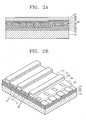
- FIG. 2B A perspective view of an organic EL device according to a first embodiment of the present invention, which is a passive matrix, forward-emission display type, is shown in FIG. 2B.
- FIG. 2A is a sectional view of the organic EL device of FIG. 2B taken along line A-A'.
- an organic EL device includes a transparent glass substrate 31; a metal oxide layer 32, a thin metal layer 33, and a transparent spacer layer 34, which are sequentially deposited on the glass substrate 31; an indium tin oxide (ITO) anode layer 35 formed on the transparent spacer layer 34 as stripes; an inter-insulating layer 39 deposited on the transparent spacer layer 34 and the ITO anode layer 35 and patterned to expose a light emitting region of the ITO anode layer 35, as shown in FIG. 2B; an organic layer 36 on the inter-insulating layer 39; and a cathode layer 37 deposited on the organic layer 36 as a metallic total reflection layer.
- ITO indium tin oxide
- the organic layer 36 includes a hole injecting layer (HIL) contacting the exposed light emitting region of the ITO anode layer 35, a hole transporting layer (HTL), an emitting layer (EML), an electron transporting layer (ETL), and an electron injecting layer (EIL).
- HIL hole injecting layer
- HTL hole transporting layer
- EML emitting layer
- ETL electron transporting layer
- EIL electron injecting layer
- reference numeral 38 denotes a separator for insulating the cathode layer 37 to discriminate a light-emitting region and a non-light emitting region.
- the cathode layer 37 may be formed as a pattern remaining only in the light-emitting region and perpendicular to the ITO anode layer 35, so that the light-emitting region and the non-light emitting region can be separated from one another.
- the glass substrate may be formed of any transparent material.
- the metal oxide layer 32 is formed of a material layer having good adhesion to the thin metal layer 33 and the glass substrate 31. Examples of such a material layer for the metal oxide layer 32 include a SiO 2 layer, a TiO 2 layer, a Y 2 O 3 layer, a Nb 2 O 5 layer, etc.
- the thin metal layer 33 which is a semi-transparent layer capable of reflecting a portion of light and transmitting a portion of light, induces optical resonance together with the anode layer 37. Any metal layer can reflect and transmit light as long as it is deposited as a thin layer. However, for higher emission efficiency, it is preferable that the thin metal layer 33 is formed of silver (Ag) or aluminum (Al), which less absorbs light. A metal alloy, such as Ag-Cu-Au (ACA) or Ag-Pd-Cu (APC), may be used for a durable thin metal layer. In addition to the thin metal layer 33, another semitransparent layer capable of transmitting and reflecting light may be formed of a material different from the thin metal layer 33.
- ACA Ag-Cu-Au
- APC Ag-Pd-Cu
- another semitransparent layer capable of transmitting and reflecting light may be formed of a material different from the thin metal layer 33.
- the distance between the cathode layer 37 and the thin metal layer 33 is adjusted to induce optical resonance when light transmission and reflection occur repeatedly between two reflector layers, i.e., the cathode layer 37 and the thin metal layer 33, causing interference.
- a structure including two reflection surfaces appropriately spaced apart to induce optical resonance is referred to as a "microcavity structure".
- the organic EL device according to the embodiment of the present invention requires the following conditions to induce optical resonance.
- a first requisite is the reflectivity of the semi-transparent thin metal layer 33.
- the reflectivity of the thin metal layer 33 varies depending on the kind of metal or alloy used and the film deposition conditions, but mainly it depends on the thickness of the thin metal layer 33.
- the depth of transmission of light to the thin metal layer 33 varies depending on the metal composing the thin metal layer 33, so it is desirable to experimentally determine the optimal thickness of the thin metal layer 33, as opposed to using theoretical data.
- a second requisite is the optical distance between the cathode layer 37 and the thin metal layer 33.
- the optical distance from the top of the thin metal layer 33 to the bottom of the cathode layer 37 is equal to the sum of the optical thicknesses of the layers between the thin metal layer 33 and the cathode layer 37, wherein the optical thickness of each of the layers is the product of the refractive index and the geometric thickness of the layer.
- the optical thicknesses of layers vary depending on their refractive indices even when having the same geometric thickness.
- the refractive index is a function of wavelength
- the optical thickness of a layer varies depending on the wavelength of light.
- the refractive indices of the layers composing an organic EL device according to the first embodiment of the present invention, for blue light having a peak wavelength of 460 nm is shown in Table 1 below.
- Layer Material Refractive Index .
- Thickness ( ⁇ ) Cathode Layer Al First reflection surface 600 EIL 1.7111 0 ETL 1.7126 260 EML(Blue) 1.7625 300 EML(Green) 1.7126 430 EML(Red) 1.669 300 HTL 1.8707 150 HIL 1.8934 700
- the refractive indices are experimental data.
- the optical distance between the first reflection surface and the second reflection surface is equal to the sum of the product of the refractive index and the geometric thickness of each of the layers between the cathode layer 37 and the thin metal layer 33.
- the sum of the optical thicknesses of the layers on the left side of equation (1) above should be equal to an integer multiple of the half bandwidth of each of the peak wavelengths of red, green, and blue light. This can be achieved by adjusting the thickness of the transparent spacer layer 34 to an appropriate level.
- the least common multiple of the sums of the optical thicknesses of the layers is selected. As shown in Table 1 above, when the transparent spacer layer 34 is formed of Nb 2 O 5 to have a thickness of 3500A, the requirement for the sum of the optical thicknesses of the layers, i.e., to be the least common multiple is satisfied, and optical resonance can be induced.
- T 1 and R 1 denote the transmittance and the reflectance of the uppermost cathode layer 37, respectively
- T 2 and R 2 denote the transmittance and the reflectance of the semi-transparent thin metal layer 33
- k is a decay constant
- d is the geometric thickness of the multiple layers between the cathode layer 37 and the thin metal layer 33
- ⁇ is a light emission angle from the multiple layers between the cathode layer 37 and the thin metal layer 33
- ⁇ is the wavelength of light.
- the ratio of amplifying the front transmission for each color of light in the organic EL device according to the first embodiment of the present invention compared to a conventional EL device having no metal reflection layer was calculated while varying the reflectance of the thin metal (reflectance) layer 33, with the assumption that the total reflectance at the boundary between a SiO 2 layer and a ITO substrate of the conventional EL device is 1.8%.
- the results are shown in Table 2 below. Reflectance 40% 50% 60% Red light 2.4 2.7 3.1 Green light 2.3 2.6 2.9 Blue light 1.9 2.0 2.1
- the semi-transparent thin metal layer 33 is designed to have an appropriate reflectance.
- an organic EL device with enhanced luminance, at least double, can be manufactured.
- the driving voltage is relatively low at a given luminance, so that less power is consumed with extended lifetime.
- the organic EL device according to the first embodiment of the present invention utilizes optical resonance, so that the half bandwidth for each color of light in the photoluminescent spectra becomes narrow, and color purity is improved.
- An organic EL device having a desired peak emission can be implemented by adjusting the thickness of the layers composing the organic EL device according to the present invention.
- the stacked structure of the thin metal layer 33, the transparent spacer layer 34, and the anode layer 35 has a capacitance, like a capacitor, and causes coupling between cathode stripes, thereby degrading picture quality.
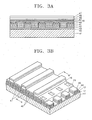
- the transparent spacer layer 34 and the thin metal layer 33 may be formed as stripes aligned with the stripes of the anode layer 35, as shown in FIGS. 3A and 3B.
- FIG. 3B is a perspective view of an organic EL device according to a second embodiment of the present invention
- FIG. 3A is a sectional view of the organic EL device of FIG. 3B taken along line B-B'.
- an organic EL device includes: a transparent glass substrate 41; a metal oxide layer 42 deposited on the glass substrate 41; a thin metal layer 43, a transparent spacer layer 44, and an ITO anode layer 45, which are sequentially deposited on the metal anode layer 42 and patterned as stripes; an inter-insulating layer 49 deposited on the ITO anode layer 45 and the metal oxide layer 42 between the stripes of the ITO anode layer 45, the transparent spacer layer 44, and the thin metal layer 43 and patterned to expose a light-emitting region of the ITO anode layer 45; an organic layer 46 including an HIL contacting the exposed region of the ITO anode layer 45, a HTL, an EML, an ETL, and an EIL, which are sequentially stacked upon one another; and a cathode layer 47 deposited on the organic layer 46 as a metallic total reflection layer.
- reference numeral 48 denotes a separator for insulating the cathode layer 47 to discriminate a light-emitting region and a non-light emitting region.
- the cathode layer 47 may be formed as a pattern remaining only in the light-emitting region and perpendicular to the ITO anode layer 45, so that the light-emitting region and the non-light emitting region can be separated from one another.
- the organic EL device according to the second embodiment of the present invention are the same as the organic EL device according to the first embodiment described above with reference to FIGS. 2A and 2B, except for the structures of the thin metal layer 43 and the transparent spacer layer 44 formed as stripes aligned with the stripes of the anode layer 45. Thus, detailed descriptions on the functions of the layers constructing the organic EL device according to the second embodiment of the present invention are not repeated here.
- the optical distance between the thin metal layer 43 and the cathode layer 47 i.e., the optical thicknesses of the multiple layers forming the microcavity structure
- the optical distance (thickness) between the thin metal layer 43 and the cathode layer 47 is determined to be the least common multiple of the half bandwidths of the red, green, and blue peak wavelengths
- the thickness of the transparent spacer layer 44 is adjusted according to the determined optical thickness to manufacture an organic EL device providing photoluminescent spectra having desired peak wavelengths of red, green, and blue light. Equations (1) and (2) and Tables 1 and 2 applied in the first embodiment described above can be applied for the organic EL device according to the second embodiment of the present invention.
- the inventors suggests organic EL devices described in the following third and fourth embodiments of the present invention.
- FIG. 4 is a sectional view of an organic EL device according to a third embodiment of the present invention.
- an organic ED device includes a glass substrate 51; a metal oxide layer 52 deposited on the glass substrate 51; a first ITO anode layer 55a, a thin metal layer 53, and a second ITO anode layer 55b, which are sequentially stacked upon one another and patterned as stripes; an inter-insulating layer 59 deposited over the structure and patterned to expose a light-emitting region of the top surface of the second ITO layer 55b; an organic layer 56 deposited on the inter-insulating layer 59 and the exposed region of the second ITO anode layer 55b as a pattern perpendicular to the stripe pattern of the second ITO anode layer 55b; and a cathode layer formed on the organic layer 59 as a metallic total reflection layer.
- the first ITO anode layer 55a instead of the transparent spacer layer 44(34) is formed underneath the thin metal layer 53tahode layer 57, and the thickness of the first ITO anode layer 55a is controlled to manufacture a microcavity structure satisfying the requirements.
- light transmittance slightly drops, compared when using the transparent spacer layer 44(34), but can be considerably increased by appropriately controlling the thickness of the first ITO anode layer 55a.
- the rectifying characteristics of the organic EL device according to the third embodiment of the present invention may degrade with an etching profile.
- the first anode layer 55a underneath the thin metal layer 63 is removed in an organic EL device according to a fourth embodiment of the present invention.
- FIG. 5 is a sectional view of an organic EL device according to the fourth embodiment of the present invention.
- an organic EL device according to the fourth embodiment of the present invention includes a glass substrate 61; a metal oxide layer 62 formed on the glass substrate 61; a thin metal layer 63 and an ITO anode layer 65, which are sequentially stacked upon one another and patterned as stripes; an inter-insulating layer 69 deposited over the structure and patterned to expose a light-emitting region of the surface of the ITO anode layer 65; an organic layer 66 formed on the inter-insulating layer 69 and the exposed region of the ITO anode layer 65 as a pattern perpendicular to the stripe pattern of the thin metal layer 63; and a cathode layer 67 formed on the organic layer 66.
- the ITO anode layer 65 contacts the thin metal layer 63, resistance becomes low at a reduced thickness of the stacked structure, thereby eliminating a problem arising from anodic resistance. Moreover, there is no need for an external auxiliary electrode, and thus, the manufacturing process is simplified at low costs.
- the present invention has been particularly described in the above with reference to embodiments thereof, the above embodiments of the present invention are for illustrative purposes and are not intended to limit the scope of the invention.
- the refractive indices and the thicknesses of the layers, in addition to the transparent spacer layer, composing a microcavity structure according to the present invention can be controlled for effective constructive interference of red, green, and blue light and that the materials for the layers can be appropriately varied, without departing from the spirit and scope of the invention as defined by the appended claims.
- an organic EL device can induce optical resonance with a simple stacked structure including an additional semi-transparent, thin metal layer, to emit peak wavelengths of red, green, and blue light with great emission efficiency. Therefore, the organic EL device according to the present invention can display high-color purity, quality images.
Landscapes
- Physics & Mathematics (AREA)
- Optics & Photonics (AREA)
- Electroluminescent Light Sources (AREA)
- Optical Filters (AREA)
Applications Claiming Priority (2)
| Application Number | Priority Date | Filing Date | Title |
|---|---|---|---|
| KR2002056813 | 2002-09-18 | ||
| KR1020020056813A KR100875097B1 (ko) | 2002-09-18 | 2002-09-18 | 광학 공진 효과를 이용한 유기 전계발광 소자 |
Publications (2)
| Publication Number | Publication Date |
|---|---|
| EP1401034A2 true EP1401034A2 (fr) | 2004-03-24 |
| EP1401034A3 EP1401034A3 (fr) | 2005-09-14 |
Family
ID=31944883
Family Applications (1)
| Application Number | Title | Priority Date | Filing Date |
|---|---|---|---|
| EP03255847A Ceased EP1401034A3 (fr) | 2002-09-18 | 2003-09-18 | Dispositif organique électroluminescent utilisant l'effet de resonance optique |
Country Status (5)
| Country | Link |
|---|---|
| US (1) | US7098590B2 (fr) |
| EP (1) | EP1401034A3 (fr) |
| JP (1) | JP5131717B2 (fr) |
| KR (1) | KR100875097B1 (fr) |
| CN (1) | CN100420064C (fr) |
Cited By (9)
| Publication number | Priority date | Publication date | Assignee | Title |
|---|---|---|---|---|
| WO2006013373A3 (fr) * | 2004-08-04 | 2006-03-23 | Cambridge Display Tech Ltd | Dispositif organique electroluminescent |
| EP1657764A1 (fr) | 2004-11-10 | 2006-05-17 | Samsung SDI Co., Ltd. | Dispositif électroluminescent à cavité résonnante optique |
| WO2006097711A1 (fr) * | 2005-03-15 | 2006-09-21 | Cambridge Display Technology Limited | Dispositif émissif de lumière |
| WO2007004106A1 (fr) * | 2005-06-30 | 2007-01-11 | Koninklijke Philips Electronics N.V. | Dispositif luminescent |
| GB2433833A (en) * | 2005-12-28 | 2007-07-04 | Cdt Oxford Ltd | Micro-cavity OLED layer structure with transparent electrode |
| EP2051312A2 (fr) | 2007-10-17 | 2009-04-22 | Samsung Electronics Co., Ltd. | Dispositif électroluminescent organique et appareil d'affichage couleur l'utilisant |
| EP2172991A1 (fr) | 2008-10-03 | 2010-04-07 | Thomson Licensing, Inc. | OLED doté d'une électrode semi-transparente pour améliorer l'extraction de la lumière dans une large gamme de longueurs d'onde |
| CN1708198B (zh) * | 2004-05-28 | 2010-05-05 | 三星移动显示器株式会社 | 有机发光装置及其制造方法 |
| US8362688B2 (en) | 2005-03-25 | 2013-01-29 | Semiconductor Energy Laboratory Co., Ltd. | Light emitting device |
Families Citing this family (57)
| Publication number | Priority date | Publication date | Assignee | Title |
|---|---|---|---|---|
| JP4371297B2 (ja) * | 2002-10-02 | 2009-11-25 | パイオニア株式会社 | 有機elディスプレイ |
| JP2004327634A (ja) * | 2003-04-23 | 2004-11-18 | Semiconductor Energy Lab Co Ltd | レーザ発振器 |
| KR100527187B1 (ko) * | 2003-05-01 | 2005-11-08 | 삼성에스디아이 주식회사 | 고효율 유기전계 발광표시장치 및 그의 제조방법 |
| CN1813382A (zh) * | 2003-06-27 | 2006-08-02 | 株式会社半导体能源研究所 | 有机激光器件 |
| US20050008052A1 (en) * | 2003-07-01 | 2005-01-13 | Ryoji Nomura | Light-emitting device |
| US7030553B2 (en) * | 2003-08-19 | 2006-04-18 | Eastman Kodak Company | OLED device having microcavity gamut subpixels and a within gamut subpixel |
| JP2005093329A (ja) * | 2003-09-19 | 2005-04-07 | Sony Corp | 表示素子およびこれを用いた表示装置 |
| KR100611157B1 (ko) * | 2003-11-29 | 2006-08-09 | 삼성에스디아이 주식회사 | 유기전계발광소자 및 그의 제조방법 |
| KR100705312B1 (ko) * | 2004-03-22 | 2007-04-10 | 엘지전자 주식회사 | 유기 전계발광소자 및 그 제조방법 |
| KR100704258B1 (ko) * | 2004-06-02 | 2007-04-06 | 세이코 엡슨 가부시키가이샤 | 유기 el 장치 및 전자 기기 |
| JP4419691B2 (ja) * | 2004-06-02 | 2010-02-24 | セイコーエプソン株式会社 | 有機el装置、電子機器 |
| JP2006032315A (ja) * | 2004-06-14 | 2006-02-02 | Seiko Epson Corp | 発光装置、電子機器、投射型表示装置、ラインヘッドおよび画像形成装置 |
| JP2006019087A (ja) * | 2004-06-30 | 2006-01-19 | Optrex Corp | 有機el表示素子の製造方法 |
| JP4693593B2 (ja) * | 2004-11-16 | 2011-06-01 | 京セラ株式会社 | 発光装置 |
| WO2006073908A2 (fr) * | 2004-12-30 | 2006-07-13 | E.I. Dupont De Nemours And Company | Dispositif electronique possedant un empilement miroir |
| WO2006098188A1 (fr) * | 2005-03-17 | 2006-09-21 | Idemitsu Kosan Co., Ltd. | Dispositif électroluminescent organique |
| EP1891691B1 (fr) * | 2005-06-03 | 2012-08-01 | Philips Intellectual Property & Standards GmbH | Source lumineuse electroluminescente organique |
| US7531955B2 (en) * | 2005-07-12 | 2009-05-12 | Eastman Kodak Company | OLED device with improved efficiency and robustness |
| JP4378366B2 (ja) * | 2005-08-04 | 2009-12-02 | キヤノン株式会社 | 発光素子アレイ |
| JP4645587B2 (ja) * | 2006-02-03 | 2011-03-09 | ソニー株式会社 | 表示素子および表示装置 |
| JP4899929B2 (ja) * | 2007-02-28 | 2012-03-21 | セイコーエプソン株式会社 | 表示装置 |
| US20080238297A1 (en) * | 2007-03-29 | 2008-10-02 | Masuyuki Oota | Organic el display and method of manufacturing the same |
| JP5008486B2 (ja) * | 2007-07-19 | 2012-08-22 | キヤノン株式会社 | 表示装置 |
| JP2009064703A (ja) * | 2007-09-07 | 2009-03-26 | Sony Corp | 有機発光表示装置 |
| JP4450051B2 (ja) * | 2007-11-13 | 2010-04-14 | ソニー株式会社 | 表示装置 |
| JP4843627B2 (ja) * | 2008-03-07 | 2011-12-21 | 株式会社 日立ディスプレイズ | 有機発光素子 |
| JP5164825B2 (ja) * | 2008-12-19 | 2013-03-21 | キヤノン株式会社 | 有機発光素子 |
| KR101009717B1 (ko) * | 2009-01-28 | 2011-01-19 | 네오뷰코오롱 주식회사 | 미세 공동 효과를 이용하는 유기전계발광소자 |
| US20120286255A1 (en) * | 2009-12-28 | 2012-11-15 | Sumitomo Chemical Company, Limited | Organic el element and organic el panel |
| US8917447B2 (en) * | 2010-01-13 | 2014-12-23 | 3M Innovative Properties Company | Microreplicated film for attachment to autostereoscopic display components |
| WO2011114424A1 (fr) | 2010-03-15 | 2011-09-22 | パイオニア株式会社 | Panneau électroluminescent organique et son procédé de production |
| US8835962B2 (en) * | 2010-05-13 | 2014-09-16 | Sri International | Cavity electroluminescent devices with integrated microlenses |
| JP2012038542A (ja) * | 2010-08-06 | 2012-02-23 | Canon Inc | 発光素子 |
| KR101365671B1 (ko) * | 2010-08-26 | 2014-02-24 | 한국전자통신연구원 | 유기전계발광소자 |
| US8547015B2 (en) | 2010-10-20 | 2013-10-01 | 3M Innovative Properties Company | Light extraction films for organic light emitting devices (OLEDs) |
| US8469551B2 (en) | 2010-10-20 | 2013-06-25 | 3M Innovative Properties Company | Light extraction films for increasing pixelated OLED output with reduced blur |
| KR101695376B1 (ko) | 2010-10-22 | 2017-01-12 | 삼성디스플레이 주식회사 | 표시 장치 및 표시 장치의 제조 방법 |
| US8692446B2 (en) | 2011-03-17 | 2014-04-08 | 3M Innovative Properties Company | OLED light extraction films having nanoparticles and periodic structures |
| JP2012156136A (ja) * | 2012-03-09 | 2012-08-16 | Sony Corp | 有機発光表示装置 |
| JP2014110143A (ja) | 2012-11-30 | 2014-06-12 | Samsung Display Co Ltd | 有機el素子 |
| KR102113177B1 (ko) | 2013-08-27 | 2020-06-03 | 삼성디스플레이 주식회사 | 유기 발광 표시 장치 및 유기 발광 표시 장치의 제조 방법 |
| KR102060018B1 (ko) | 2013-11-26 | 2019-12-30 | 엘지디스플레이 주식회사 | 유기 발광 장치 |
| CN103779387B (zh) * | 2014-01-06 | 2018-11-02 | 京东方科技集团股份有限公司 | Oled显示面板及显示装置 |
| KR102215147B1 (ko) * | 2014-08-14 | 2021-02-15 | 삼성디스플레이 주식회사 | 유기발광 표시장치 |
| CN104465671B (zh) * | 2014-12-26 | 2016-08-31 | 京东方科技集团股份有限公司 | 一种显示基板及其制作方法、显示装置 |
| US9859451B2 (en) | 2015-06-26 | 2018-01-02 | International Business Machines Corporation | Thin film photovoltaic cell with back contacts |
| CN105098094B (zh) * | 2015-07-20 | 2017-11-17 | 上海和辉光电有限公司 | 显示面板及其oled元件 |
| JP7034584B2 (ja) * | 2016-10-21 | 2022-03-14 | キヤノン株式会社 | 表示装置及び撮像装置 |
| CN109841747B (zh) * | 2017-11-27 | 2021-09-24 | 上海和辉光电股份有限公司 | 一种有机发光显示面板及显示装置 |
| KR102199495B1 (ko) * | 2018-05-21 | 2021-01-06 | 한국과학기술원 | 색 순도 향상 필터 |
| US11031577B1 (en) | 2019-11-26 | 2021-06-08 | OLEDWorks LLC | Multimodal microcavity OLED with multiple blue emitting layers |
| KR102820733B1 (ko) * | 2020-08-21 | 2025-06-16 | 삼성디스플레이 주식회사 | 유기발광 다이오드 및 그 제조방법 |
| KR20220090667A (ko) * | 2020-12-22 | 2022-06-30 | 삼성디스플레이 주식회사 | 발광 소자 및 이를 포함한 전자 장치 |
| CN116670743A (zh) * | 2020-12-29 | 2023-08-29 | 株式会社半导体能源研究所 | 显示装置的制造方法 |
| CN113054124A (zh) * | 2021-02-20 | 2021-06-29 | 京东方科技集团股份有限公司 | 一种有机发光器件、显示装置、制作方法以及存储介质 |
| US12604650B2 (en) * | 2021-12-20 | 2026-04-14 | Semiconductor Energy Laboratory Co., Ltd. | Method for manufacturing light-emitting element and light-emitting device using photolithography technique |
| JP7838899B2 (ja) * | 2022-06-07 | 2026-04-01 | 東京エレクトロン株式会社 | 基板処理方法及び基板処理装置 |
Citations (1)
| Publication number | Priority date | Publication date | Assignee | Title |
|---|---|---|---|---|
| US20020075439A1 (en) * | 2000-10-31 | 2002-06-20 | Hideki Uehara | Electro-optical device, inspection method therefor, and electronic equipment |
Family Cites Families (33)
| Publication number | Priority date | Publication date | Assignee | Title |
|---|---|---|---|---|
| JPH046157Y2 (fr) * | 1986-12-26 | 1992-02-20 | ||
| US5283692A (en) * | 1989-07-21 | 1994-02-01 | Spectra Physics Lasers, Inc. | Multi-layer graded reflectivity mirror |
| JPH06230211A (ja) * | 1991-03-29 | 1994-08-19 | Idemitsu Kosan Co Ltd | カラーフィルタ及びその製造方法並びに該カラーフィルタを用いたカラー液晶ディスプレイ及びその駆動方法 |
| JPH04254887A (ja) * | 1991-02-06 | 1992-09-10 | Pioneer Electron Corp | 有機el表示装置 |
| US5652067A (en) * | 1992-09-10 | 1997-07-29 | Toppan Printing Co., Ltd. | Organic electroluminescent device |
| JP2797883B2 (ja) * | 1993-03-18 | 1998-09-17 | 株式会社日立製作所 | 多色発光素子とその基板 |
| JP3276745B2 (ja) * | 1993-11-15 | 2002-04-22 | 株式会社日立製作所 | 可変波長発光素子とその制御方法 |
| US5701055A (en) * | 1994-03-13 | 1997-12-23 | Pioneer Electronic Corporation | Organic electoluminescent display panel and method for manufacturing the same |
| US5478658A (en) * | 1994-05-20 | 1995-12-26 | At&T Corp. | Article comprising a microcavity light source |
| JP2850820B2 (ja) * | 1995-02-09 | 1999-01-27 | 株式会社デンソー | El素子 |
| US5952037A (en) * | 1995-03-13 | 1999-09-14 | Pioneer Electronic Corporation | Organic electroluminescent display panel and method for manufacturing the same |
| US5780174A (en) * | 1995-10-27 | 1998-07-14 | Kabushiki Kaisha Toyota Chuo Kenkyusho | Micro-optical resonator type organic electroluminescent device |
| US5814416A (en) * | 1996-04-10 | 1998-09-29 | Lucent Technologies, Inc. | Wavelength compensation for resonant cavity electroluminescent devices |
| US5949187A (en) * | 1997-07-29 | 1999-09-07 | Motorola, Inc. | Organic electroluminescent device with plural microcavities |
| US5998805A (en) * | 1997-12-11 | 1999-12-07 | Motorola, Inc. | Active matrix OED array with improved OED cathode |
| US6133692A (en) | 1998-06-08 | 2000-10-17 | Motorola, Inc. | White light generating organic electroluminescent device and method of fabrication |
| JP2000098931A (ja) * | 1998-07-24 | 2000-04-07 | Seiko Epson Corp | 表示装置 |
| JP4260972B2 (ja) * | 1999-03-30 | 2009-04-30 | ソニー株式会社 | 光学記録媒体 |
| GB2349979A (en) | 1999-05-10 | 2000-11-15 | Cambridge Display Tech Ltd | Light-emitting devices |
| GB2351840A (en) * | 1999-06-02 | 2001-01-10 | Seiko Epson Corp | Multicolour light emitting devices. |
| US6469439B2 (en) * | 1999-06-15 | 2002-10-22 | Toray Industries, Inc. | Process for producing an organic electroluminescent device |
| ATE376707T1 (de) | 1999-07-09 | 2007-11-15 | Osram Opto Semiconductors Gmbh | Verkapselung einer vorrichtung |
| WO2001006576A1 (fr) * | 1999-07-19 | 2001-01-25 | Uniax Corporation | Dispositifs electroluminescents polymeres a longue duree de vie presentant un rendement lumineux et une luminance energetique ameliores |
| GB2353400B (en) * | 1999-08-20 | 2004-01-14 | Cambridge Display Tech Ltd | Mutiple-wavelength light emitting device and electronic apparatus |
| JP4174989B2 (ja) * | 1999-11-22 | 2008-11-05 | ソニー株式会社 | 表示装置 |
| JP4637390B2 (ja) * | 2000-03-27 | 2011-02-23 | 株式会社半導体エネルギー研究所 | 発光装置の作製方法 |
| WO2002021883A1 (fr) | 2000-09-06 | 2002-03-14 | Osram Opto Semiconductors Gmbh | Formation de motifs d'electrodes dans un dispositif a diodes electroluminescentes organiques |
| TW533446B (en) * | 2000-12-22 | 2003-05-21 | Koninkl Philips Electronics Nv | Electroluminescent device and a method of manufacturing thereof |
| JP2002216977A (ja) * | 2001-01-22 | 2002-08-02 | Matsushita Electric Ind Co Ltd | 有機エレクトロルミネッセンス表示素子 |
| JP2002251145A (ja) * | 2001-02-23 | 2002-09-06 | Matsushita Electric Ind Co Ltd | 発光表示装置 |
| US6680570B2 (en) | 2001-03-21 | 2004-01-20 | Agilent Technologies, Inc. | Polymer organic light emitting device with improved color control |
| CN1666579A (zh) * | 2002-05-08 | 2005-09-07 | 泽奥勒克斯公司 | 使用反馈增强型发光二极管的照明器件 |
| US20040031965A1 (en) * | 2002-08-16 | 2004-02-19 | Forrest Stephen R. | Organic photonic integrated circuit using an organic photodetector and a transparent organic light emitting device |
-
2002
- 2002-09-18 KR KR1020020056813A patent/KR100875097B1/ko not_active Expired - Lifetime
-
2003
- 2003-09-17 US US10/663,762 patent/US7098590B2/en not_active Expired - Lifetime
- 2003-09-18 EP EP03255847A patent/EP1401034A3/fr not_active Ceased
- 2003-09-18 CN CNB031255876A patent/CN100420064C/zh not_active Expired - Lifetime
- 2003-09-18 JP JP2003326453A patent/JP5131717B2/ja not_active Expired - Lifetime
Patent Citations (1)
| Publication number | Priority date | Publication date | Assignee | Title |
|---|---|---|---|---|
| US20020075439A1 (en) * | 2000-10-31 | 2002-06-20 | Hideki Uehara | Electro-optical device, inspection method therefor, and electronic equipment |
Cited By (17)
| Publication number | Priority date | Publication date | Assignee | Title |
|---|---|---|---|---|
| CN1708198B (zh) * | 2004-05-28 | 2010-05-05 | 三星移动显示器株式会社 | 有机发光装置及其制造方法 |
| WO2006013373A3 (fr) * | 2004-08-04 | 2006-03-23 | Cambridge Display Tech Ltd | Dispositif organique electroluminescent |
| GB2447637A (en) * | 2004-08-04 | 2008-09-24 | Cambridge Display Tech Ltd | Organic Electroluminescent Device |
| GB2447637B (en) * | 2004-08-04 | 2009-11-18 | Cambridge Display Tech Ltd | Organic Electroluminescent Device |
| US9136504B2 (en) | 2004-08-04 | 2015-09-15 | Cambridge Display Technology Limited | Organic electroluminescent device |
| EP1657764A1 (fr) | 2004-11-10 | 2006-05-17 | Samsung SDI Co., Ltd. | Dispositif électroluminescent à cavité résonnante optique |
| US8525154B2 (en) | 2004-11-10 | 2013-09-03 | Samsung Display Co., Ltd. | Light-emitting device having optical resonance layer |
| WO2006097711A1 (fr) * | 2005-03-15 | 2006-09-21 | Cambridge Display Technology Limited | Dispositif émissif de lumière |
| US8362688B2 (en) | 2005-03-25 | 2013-01-29 | Semiconductor Energy Laboratory Co., Ltd. | Light emitting device |
| US9246056B2 (en) | 2005-03-25 | 2016-01-26 | Semiconductor Energy Laboratory Co., Ltd. | Light emitting device |
| WO2007004106A1 (fr) * | 2005-06-30 | 2007-01-11 | Koninklijke Philips Electronics N.V. | Dispositif luminescent |
| GB2433833A (en) * | 2005-12-28 | 2007-07-04 | Cdt Oxford Ltd | Micro-cavity OLED layer structure with transparent electrode |
| US8294341B2 (en) | 2005-12-28 | 2012-10-23 | Cdt Oxford Limited | Organic electroluminescent device |
| EP2051312A3 (fr) * | 2007-10-17 | 2011-05-25 | Samsung Electronics Co., Ltd. | Dispositif électroluminescent organique et appareil d'affichage couleur l'utilisant |
| US8587191B2 (en) | 2007-10-17 | 2013-11-19 | Samsung Display Co., Ltd. | Organic light emitting device and color display apparatus using the same |
| EP2051312A2 (fr) | 2007-10-17 | 2009-04-22 | Samsung Electronics Co., Ltd. | Dispositif électroluminescent organique et appareil d'affichage couleur l'utilisant |
| EP2172991A1 (fr) | 2008-10-03 | 2010-04-07 | Thomson Licensing, Inc. | OLED doté d'une électrode semi-transparente pour améliorer l'extraction de la lumière dans une large gamme de longueurs d'onde |
Also Published As
| Publication number | Publication date |
|---|---|
| JP5131717B2 (ja) | 2013-01-30 |
| JP2004111398A (ja) | 2004-04-08 |
| EP1401034A3 (fr) | 2005-09-14 |
| US20040056590A1 (en) | 2004-03-25 |
| CN100420064C (zh) | 2008-09-17 |
| KR100875097B1 (ko) | 2008-12-19 |
| US7098590B2 (en) | 2006-08-29 |
| KR20040025025A (ko) | 2004-03-24 |
| CN1496206A (zh) | 2004-05-12 |
Similar Documents
| Publication | Publication Date | Title |
|---|---|---|
| US7098590B2 (en) | Organic electroluminescent device using optical resonance effect | |
| KR101434361B1 (ko) | 백색 유기 전계 발광소자 및 이를 이용한 컬러 디스플레이장치 | |
| EP0616488B1 (fr) | Eléments émetteurs de lumière | |
| US8680543B2 (en) | Light Emitting Element Having a Capping Layer on an Electrode, Light Emitting Device Having the Same and Method for Manufacturing the Same | |
| KR101434362B1 (ko) | 유기 전계 발광소자 및 이를 이용한 컬러 디스플레이 장치 | |
| US7180238B2 (en) | Oled microcavity subpixels and color filter elements | |
| KR101235545B1 (ko) | 유기 el 표시 장치 | |
| CN102077386B (zh) | 发光显示装置 | |
| JP4951130B2 (ja) | 有機発光素子及びその製造方法 | |
| US7733013B2 (en) | Display apparatus | |
| KR101528242B1 (ko) | 백색 유기 전계 발광소자 및 이를 이용한 컬러 디스플레이장치 | |
| US8188500B2 (en) | Organic light-emitting element and light-emitting device using the same | |
| US9343510B2 (en) | Organic light emitting display device | |
| JP2003115377A (ja) | 発光素子、その製造方法およびこれを用いた表示装置 | |
| JP2011065992A (ja) | 有機発光ディスプレイ装置 | |
| US20060181204A1 (en) | Flexible organic light emitting devices | |
| JP2004319100A (ja) | Elディスプレイ | |
| KR20090112090A (ko) | 유기 발광 표시 장치 및 그 제조 방법 | |
| CN113178526B (zh) | 一种电致发光器件及显示装置 | |
| KR20120027460A (ko) | 발광소자 및 표시장치 | |
| JP4769068B2 (ja) | 有機発光素子及びその製造方法 | |
| JP4104339B2 (ja) | 発光素子及びその製造方法、並びに表示装置 | |
| KR100796602B1 (ko) | 유기전계발광소자 및 그의 제조방법 | |
| KR20260057421A (ko) | 디스플레이 패널 및 디스플레이 장치 | |
| KR20190112256A (ko) | 다층 구조로 형성된 절연층을 포함하는 유기 발광 표시 장치 |
Legal Events
| Date | Code | Title | Description |
|---|---|---|---|
| PUAI | Public reference made under article 153(3) epc to a published international application that has entered the european phase |
Free format text: ORIGINAL CODE: 0009012 |
|
| AK | Designated contracting states |
Kind code of ref document: A2 Designated state(s): AT BE BG CH CY CZ DE DK EE ES FI FR GB GR HU IE IT LI LU MC NL PT RO SE SI SK TR |
|
| AX | Request for extension of the european patent |
Extension state: AL LT LV MK |
|
| RAP1 | Party data changed (applicant data changed or rights of an application transferred) |
Owner name: SAMSUNG SDI CO., LTD. |
|
| PUAL | Search report despatched |
Free format text: ORIGINAL CODE: 0009013 |
|
| AK | Designated contracting states |
Kind code of ref document: A3 Designated state(s): AT BE BG CH CY CZ DE DK EE ES FI FR GB GR HU IE IT LI LU MC NL PT RO SE SI SK TR |
|
| AX | Request for extension of the european patent |
Extension state: AL LT LV MK |
|
| 17P | Request for examination filed |
Effective date: 20060215 |
|
| AKX | Designation fees paid |
Designated state(s): DE FR GB |
|
| RAP1 | Party data changed (applicant data changed or rights of an application transferred) |
Owner name: SAMSUNG MOBILE DISPLAY CO., LTD. |
|
| 17Q | First examination report despatched |
Effective date: 20090408 |
|
| RAP1 | Party data changed (applicant data changed or rights of an application transferred) |
Owner name: SAMSUNG DISPLAY CO., LTD. |
|
| STAA | Information on the status of an ep patent application or granted ep patent |
Free format text: STATUS: THE APPLICATION HAS BEEN REFUSED |
|
| 18R | Application refused |
Effective date: 20140512 |
|
| REG | Reference to a national code |
Ref country code: DE Ref legal event code: R079 Free format text: PREVIOUS MAIN CLASS: H01L0051200000 Ipc: H01L0051050000 |
|
| REG | Reference to a national code |
Ref country code: DE Ref legal event code: R079 Free format text: PREVIOUS MAIN CLASS: H01L0051200000 Ipc: H01L0051050000 Effective date: 20141001 |