EP1400644A1 - Fanghakeneinrichtung für eine Fronthaube eines Kraftfahrzeugs - Google Patents
Fanghakeneinrichtung für eine Fronthaube eines Kraftfahrzeugs Download PDFInfo
- Publication number
- EP1400644A1 EP1400644A1 EP03021028A EP03021028A EP1400644A1 EP 1400644 A1 EP1400644 A1 EP 1400644A1 EP 03021028 A EP03021028 A EP 03021028A EP 03021028 A EP03021028 A EP 03021028A EP 1400644 A1 EP1400644 A1 EP 1400644A1
- Authority
- EP
- European Patent Office
- Prior art keywords
- control lever
- catch
- hook
- fishing hook
- lever
- Prior art date
- Legal status (The legal status is an assumption and is not a legal conclusion. Google has not performed a legal analysis and makes no representation as to the accuracy of the status listed.)
- Granted
Links
- 230000000903 blocking effect Effects 0.000 claims description 4
- 210000001331 nose Anatomy 0.000 description 3
- 230000015572 biosynthetic process Effects 0.000 description 2
- 230000003993 interaction Effects 0.000 description 2
- 230000003750 conditioning effect Effects 0.000 description 1
- 230000001419 dependent effect Effects 0.000 description 1
- 238000006073 displacement reaction Methods 0.000 description 1
- 238000000034 method Methods 0.000 description 1
Images

Classifications
-
- E—FIXED CONSTRUCTIONS
- E05—LOCKS; KEYS; WINDOW OR DOOR FITTINGS; SAFES
- E05B—LOCKS; ACCESSORIES THEREFOR; HANDCUFFS
- E05B83/00—Vehicle locks specially adapted for particular types of wing or vehicle
- E05B83/16—Locks for luggage compartments, car boot lids or car bonnets
- E05B83/24—Locks for luggage compartments, car boot lids or car bonnets for car bonnets
Definitions
- the invention relates to a catch hook device for a front hood of a motor vehicle, with the features specified in the preamble of claim 1.
- Such a fishing hook device is described in DE 100 19 587 A1, for example a hinged front hood of a motor vehicle and has a Fanghook on, which is in a closed or in a gap opening position befind another Front hood is held by a locking part in a catch position, resulting in the bonnet does not open completely. Is the catch hook on a in the Slotted opening position pivoting release lever unlocked manually, the Front hood over the gap opening position to be opened.
- the description is removable, that by an oblique formation of the lower edge of the fishing hook is to be achieved that when closing the open bonnet of the Catch hook in cooperation with the striker automatically from the striker weg shift away, then by spring force an automatic grip behind to allow the striker by the fishing hook.
- the invention is based on the object, a fishing hook device with the Specify features in the preamble of claim 1, when closing the open front hood on the one hand locked in the open position of the front cover Catch hook automatically unlocked and on the other hand an automatic grip behind the striker or the like by the fishing hook allows.
- pivoting control lever when closing the open Front hood on the striker or on another part of the system Plant comes and cooperating in a the locking device of the fishing hook unlocked unlocking pivoted, can on further closing the front hood by an interaction of a run-on slope or the like on the fishing hook with the striker spring-loaded fishing hook the striker to engage automatically.
- the joystick is following his Swiveling into the unlocking position for so long in the unlocking position hold until subsequently the fishing hook reaches the striker and engages behind Has. This can be done in a simple manner by that on the control lever a corresponding, cooperating with the striker or the other part of the system Control surface is formed.
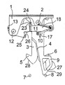
- FIG. 1 according to a first embodiment in a front view a motor vehicle illustrated fishing hook device is not shown on the Bonnet of a motor vehicle provided and has one with the front hood for example, rivets connected base plate 1 on.
- base plate 1 On the base plate 1 are about a common pivot axis 2 two catch hooks 3, 4 with opposite to the vehicle sides directed catch noses 5, 6 pivotally attached.
- the Fishing hooks 3, 4 are from the pivot axis 2 down and engage behind with closed front hood one assigned to the body of the Motor vehicle fastened striker 7, 8 or the like.
- Located in the figure not shown and at its rear to a fixed or displaceable real or virtual vehicle transverse axis pivoting front hood in one in front of a gap opening position also raised pivot position.
- the two Fishing hooks 3, 4 are spring-loaded in the illustrated fishing position.
- the two fishing hooks 3, 4 are locked by a releasable locking device.
- the bonnet is closed or raised in the gap opening position the catch noses 5, 6 respectively below the associated strikers 7, 8 and prevent in cooperation with the strikers 7, 8 in the gap opening position another lifting of the front hood, with the unlocked locking device additional security acts.
- FIG 2 also has a common pivot axis 2 of the fishing hooks 3, 4 pivoting control lever 9, by a spring element is loaded in the illustrated, limited by a stop locked position, an angular Slot 10, which is penetrated by a pin 11.
- the bolt 11 is connected to a pivotable about an axis 12 guide lever 13 and engages in each case a slot 14, 15 in the direction of the pivot axis 2 axially offset catch hooks 3 and 4.
- the slot 15 in the fishing hook 4 is only recognizable in Figure 4.
- the angular slot 10 has, as shown in Figure 2 can be seen a first slot portion 16, the pivot axis 2 of the control lever 9 approximately radially and in the figure 4 corresponding unlocking position of the control lever 9 extends around the axis 12 of the guide lever 13 arcuate.
- a second slot portion 17 which is around the Swivel axis 12 of the control lever 9 is formed in a circular arc.
- the locking device is as shown in Figure 2 in its locked position when the Bolt 11 at the lower end of the first slot portion 16 and laterally in the outer End region of the second slot portion 17 is located.
- the catch hook device is in Figure 3 without the guide lever 13 and without the Control lever 9 and without a release lever indicated only in Figures 1 and 4 18 shown.
- the bolt 11 is laterally with a Pivoting lever 19, 20 connected to one of the bolt 11 and the axis of the 12th of the guide lever 13 remote pivot axis 21 and 22 on a lever arm the respectively associated fishing hooks 3 and 4 are pivotally mounted.
- the release lever 18 shown in Figures 1 and 4 is about the axis 12th pivotally attached to the base plate 1 and in a figure 1 corresponding and spring-loaded by a stop limited normal position. With closed bonnet this is locked by a hood lock, not shown. After this Unlocking the hood lock causes at least one preloaded spring Lifting the front hood in the gap opening position in which the catching located and locked by the locking device fishing hooks 3, 4 in cooperation with the associated strikers 7, 8 prevent further lifting of the bonnet. In the gap opening position, the release lever 18 can be grasped manually and anti-clockwise about the axis 12 in a catch hook unlocking position be pivoted.
- the Long holes 14, 15 in the fishing hooks 3, 4 are so inclined to each other that in this adjustment movement of the pin 11 and the pivot lever 19, 20 the two fishing hooks 3, 4 in the position shown in Figure 4 of the strikers 7, 8 away in the space between the strikers 7, 8 in the unlocking position adjust.
- the front hood can in this unlocking the fishing hooks 3, 4 and the control lever 9 is opened upwards beyond the gap opening position be, wherein after releasing the unlocking lever 18 a through the Spring force automatic return displacement of the parts in the figure 1 corresponding starting position takes place, in which the fishing hooks 3, 4 in their from the locking device locked catch position.
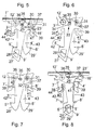
- the locking device is opposite to the first Embodiment formed differently and has a pawl 31, the order a pawl axis 30 is pivotable and in the fishing position of the fishing hook 3 'by Spring force in front of a locking shoulder 32 on the fishing hook 3 'is incident and thereby the Fishing hook 3 'locked in its catch position.
- the control lever 9 ' is a pin-slot connection 33 limited to the two fishing hooks 3 ', 4' pivotable.
- the pin-slot connection 33 has a in the control lever 9 'formed, about the pivot axis 12 'of the control lever 9' circular arc extending LanglochausEnglishung 34.
- the Ausreteslangloch 36 runs approximately parallel to the ideal connection line between the pivot axis 12 'and the pawl axis 30.
- This Axes 12 'and 30 are each above the central web of the associated striker 7 ', 8' arranged and form the pivot axes for the fishing hooks 3 ', 4'.
- each fishing hook 3 ', 4' has a support leg 38, 39th and the control lever 9 'on a support lever 44, each in a catch nose 5 ', 6' of the respective fishing hook 3 ', 4' and the control contour 27 'radially lower Distance to the respective pivot axis 12 ', 30 of the relevant fishing hook 3', 4 ' or of the control lever 9 'are formed.
- the two support legs 38, 39 limit laterally, approximately radially to the pivot axis 12 ', 30 of the relevant fishing hook 3 'and 4' extending recess 40, 41 in the fishing hooks 3 ', 4'.
- each catch hook can be assigned a separate control lever, which can be designed differently.
- a fishing hook which is associated with a control lever.
- a support wall be in cooperation with a counter-support wall on the other part, at the body of the motor vehicle or the front hood, an accidental lateral Moving the front hood prevents.
- the support wall or counter support wall can be formed by the striker.
- the locking device may be of the embodiments deviating and from a control lever directly or be detachable via interposed parts.
- the in the first embodiment used pivot lever 19, 20 can be omitted. Should not that be closer specified hood lock on the front hood while driving unintentionally solve and thereby the bonnet are adjusted in their gap opening position, the bonnet is then reliably held in the gap opening position, if there is a larger gap between the bonnet and the bodywork of the Motor vehicle is formed and thereby greater air force on the front cover in their opening direction acts.
- a larger gap formation in the gap opening position may be provided, for example, to use a safety device, which captures an impending collision with a pedestrian and in this If the hood lock releases, adjust the front hood to a higher altitude can, in which the elastically supported front hood a collision of the pedestrian can attenuate over a larger travel.
Landscapes
- Lock And Its Accessories (AREA)
- Superstructure Of Vehicle (AREA)
Abstract
Description
- Fig. 1
- ein erstes Ausführungsbeispiel mit zwei um eine gemeinsame Schwenkachse schwenkbaren Fanghaken bei über die Spaltöffnungslage angehobener Fronthaube und in Sperrlage befindlicher Sperreinrichtung,
- Fig. 2
- die Figur 1 entsprechenden Fanghaken in einer Ansicht bei geschlossener Fronthaube, ohne den Entriegelungshebel,
- Fig. 3
- eine Figur 2 entsprechende Ansicht ohne Steuerhebel, ohne Führungshebel und ohne Schließbügel,
- Fig. 4
- eine Figur 1 entsprechende Ansicht bei manuell betätigtem Entriegelungshebel und dadurch in die Entriegelungslage geschwenktem Steuerhebel,
- Fig. 5
- ein zweites Ausführungsbeispiel in einer Figur 1 entsprechenden Ansicht, mit zwei um separate Achsen schwenkbaren Fanghaken, von denen ein Fanghaken von einer Sperrklinke verriegelbar ist,
- Fig. 6
- das in Figur 5 dargestellte Ausführungsbeispiel in Sperrlage des Steuerhebels, ohne den Entriegelungshebel,
- Fig. 7
- eine Figur 6 entsprechende Ansicht ohne den Steuerhebel und
- Fig. 8
- eine Figur 5 entsprechende Ansicht bei durch manuelle Betätigung des Entriegelungshebels in die Entriegelungslage geschwenktem Steuerhebel.
Claims (14)
- Fanghakeneinrichtung für eine Fronthaube eines Kraftfahrzeugs, mit einem in eine Fanglage federbelasteten Fanghaken, der nach dem Entriegeln eines Haubenschlosses und durch Federkraft bewirkten Anheben der Fronthaube in eine Spaltöffnungslage mit einem Schließbügel oder dergleichen zusammenwirkend ein weiteres Anheben der Fronthaube verhindert und der in seiner Fanglage von einer lösbaren Sperreinrichtung arretiert und in der Spaltöffnungslage manuell von dem Schließbügel weg verstellbar ist, dadurch gekennzeichnet, dass die Sperreinrichtung einen schwenkbaren Steuerhebel (9, 9') aufweist, der in eine Sperrlage federbelastet ist, in der die Sperreinrichtung den Fanghaken (3, 4, 3', 4') arretiert, und beim Schließen der über die Spaltöffnungslage angehobenen Fronthaube der Steuerhebel (9, 9') mit dem Schließbügel (7, 8, 7', 8') oder einem anderen Anlageteil zusammenwirkend in eine die Sperreinrichtung lösende Entriegelungslage schwenkt und verbleibt, bis nachfolgend der Fanghaken (3, 4, 3', 4') mit dem Schließbügel (7, 8, 7', 8') zusammenwirkend von diesem entgegen der Federbelastung weg schwenkt, und der federbelastete Fanghaken (3, 4, 3', 4') nach dem Erreichen der Spaltöffnungslage den Schließbügel (7, 8, 7', 8') hintergreift und der Steuerhebel (9, 9') eine Schwenkbewegung in seine Sperrlage ausführt.
- Fanghakeneinrichtung nach Anspruch 1, dadurch gekennzeichnet, dass der Steuerhebel (9, 9') eine Steuerkontur (27, 27') und der Fanghaken (3, 4, 3', 4') eine ebene oder gekrümmte Anlauffläche (28, 29, 28', 29') aufweisen, die jeweils zumindest bereichsweise zur Verstellbewegung der Fronthaube geneigt ausgebildet sind und der Steuerhebel (9, 9') bzw. der Fanghaken (3, 4, 3', 4') über die Steuerkontur (27, 27') bzw. die Anlauffläche (28, 29, 28', 29') mit dem Schließbügel (7, 8, 7', 8') bzw. dem Anlageteil zusammenwirken.
- Fanghakeneinrichtung nach Anspruch 1 oder 2, dadurch gekennzeichnet, dass die Sperreinrichtung ein winkelförmiges Langloch (10) im Steuerhebel (9) aufweist, das von einem Bolzen (11) durchsetzt ist, der ein Langloch (14, 15) im Fanghaken (3, 4) durchgreift und mit einem um eine Achse (12) schwenkbaren Führungshebel (13) verbunden ist.
- Fanghakeneinrichtung nach Anspruch 3, dadurch gekennzeichnet, dass das winkelförmige Langloch (10) einen ersten Langlochbereich (16) aufweist, der zur Schwenkachse (2) des Steuerhebels (9) etwa radial und bei in Entriegelungslage befindlichem Steuerhebel (9) um die Achse (12) des Führungshebels (13) kreisbogenförmig verläuft, und der erste Langlochbereich (16) an dem von der Schwenkachse (2) des Steuerhebels (9) radial entfernten Bereich in einen zweiten Langlochbereich (17) übergeht, der um die Schwenkachse (2) des Steuerhebels kreisbogenförmig ausgebildet ist.
- Fanghakeneinrichtung nach Anspruch 4, dadurch gekennzeichnet, dass sich der Bolzen (11) bei in Sperrlage befindlichem Steuerhebel (9) im äußeren Endbereich des zweiten Langlochbereiches (17) und bei in Entriegelungslage befindlichem Steuerhebel (9) im ersten Langlochbereich (16) befindet.
- Fanghakeneinrichtung nach einem der Ansprüche 3 bis 5, dadurch gekennzeichnet, dass der Bolzen (11) an einem Schwenkhebel (19, 20) befestigt ist, der um eine von dem Bolzen (11) und der Achse (12) des Führungshebels (13) entfernte Schwenkachse (21, 22) an dem Fanghaken (3, 4) schwenkbar befestigt ist.
- Fanghakeneinrichtung nach einem der Ansprüche 3 bis 6, dadurch gekennzeichnet, dass ein in eine Normallage federbelasteter Entriegelungshebel (18) in der Spaltöffnungslage manuell in eine Fanghaken-Entriegelungslage schwenkbar ist und dabei zunächst den Steuerhebel (9) in seine Entriegelungslage schwenkt, danach den Führungshebel (13) verschwenkt und dabei den mit dem Führungshebel (13) verbundenen Bolzen (11) im zweiten Langlochbereich (17) des Langloches (10) verstellt, wodurch sich der Fanghaken (3, 4) von dem Schließbolzen (7, 8) entfernt.
- Fanghakeneinrichtung nach Anspruch 1 oder 2, dadurch gekennzeichnet, dass die Sperreinrichtung eine schwenkbare Sperrklinke (31) aufweist, die in der Fanglage des Fanghakens (3') durch Federkraft vor eine Sperrschulter (32) an dem Fanghaken (3') einfällt und dadurch den Fanghaken (3') in seiner Fanglage arretiert.
- Fanghakeneinrichtung nach Anspruch 8, dadurch gekennzeichnet, dass der Steuerhebel (9') über eine Zapfen-Langloch-Verbindung (33) begrenzt gegenüber den beiden Fanghaken (3', 4') verschwenkbar ist.
- Fanghakeneinrichtung nach Anspruch 9, dadurch gekennzeichnet, dass die Zapfen-Langloch-Verbindung (33) eine im Steuerhebel (9') ausgebildete, um die Schwenkachse (12') des Steuerhebels (12') kreisbogenförmig verlaufende Langlochausnehmung (34) aufweist und der Zapfen (35) der Zapfen-Langloch-Verbindung (33) die Langlochausnehmung (34) durchsetzt und entweder von dem Fanghaken (4') absteht oder ein Ausgleichslangloch (36) im Fanghaken oder in einem zweiten Fanghaken (3') durchdringt.
- Fanghakeneinrichtung nach einem der Ansprüche 8 bis 10, dadurch gekennzeichnet, dass ein in eine Normallage federbelasteter Entriegelungshebel (18') in der Spaltöffnungslage manuell in eine Fanghaken-Entriegelungslage schwenkbar ist und dabei zunächst die Sperrklinke (31) von der Sperrschulter (32) des Fanghakens (3') weg schwenkt und danach den Fanghaken (3', 4') von dem Schließbügel (7', 8') weg verstellt.
- Fanghakeneinrichtung nach einem der Ansprüche 8 bis 11, dadurch gekennzeichnet, dass der Fanghaken (3', 4') einen Stützschenkel (38, 39) aufweist, der in einem zur Fangnase (5', 6') des Fanghakens (3', 4') radial geringeren Abstand zur Schwenkachse (12', 30) des Fanghakens (3', 4') ausgebildet ist und eine etwa radial zur Schwenkachse (12', 30) verlaufende Vertiefung (40, 41) im Fanghaken (3', 4') seitlich begrenzt, wobei sich der Steg des Schließbügels (7', 8') bei geschlossener Fronthaube in der Vertiefung (40, 41) befindet und in der Spaltöffnungslage außerhalb der Vertiefung (40, 41) vor einer seitlichen Öffnung (42, 43) im Fanghaken (3', 4') angeordnet ist.
- Fanghakeneinrichtung nach einem der Ansprüche 1 bis 12, dadurch gekennzeichnet, dass zwei Fanghaken (3, 4 bzw. 3', 4') mit entgegengesetzt angeordneten Fangnasen (5, 6 bzw. 5', 6') vorgesehen sind, die in der Spaltöffnungslage mit jeweils einem Schließbügel (7, 8 bzw. 7', 8') zusammenwirken und den beiden Fanghaken ein gemeinsamer Steuerhebel (9 bzw. 9') zugeordnet ist.
- Fanghakeneinrichtung nach einem der Ansprüche 8 bis 13, dadurch gekennzeichnet, dass die Schwenkachsen (12', 30) der Fanghaken (3', 4') jeweils über dem Steg des dem betreffenden Fanghaken (3', 4') zugeordneten Schließbügels (7', 8') angeordnet sind.
Applications Claiming Priority (2)
| Application Number | Priority Date | Filing Date | Title |
|---|---|---|---|
| DE10243461A DE10243461A1 (de) | 2002-09-19 | 2002-09-19 | Fanghakeneinrichtung für eine Fronthaube eines Kraftfahrzeugs |
| DE10243461 | 2002-09-19 |
Publications (2)
| Publication Number | Publication Date |
|---|---|
| EP1400644A1 true EP1400644A1 (de) | 2004-03-24 |
| EP1400644B1 EP1400644B1 (de) | 2005-06-01 |
Family
ID=31896177
Family Applications (1)
| Application Number | Title | Priority Date | Filing Date |
|---|---|---|---|
| EP03021028A Expired - Lifetime EP1400644B1 (de) | 2002-09-19 | 2003-09-17 | Fanghakeneinrichtung für eine Fronthaube eines Kraftfahrzeugs |
Country Status (2)
| Country | Link |
|---|---|
| EP (1) | EP1400644B1 (de) |
| DE (2) | DE10243461A1 (de) |
Cited By (1)
| Publication number | Priority date | Publication date | Assignee | Title |
|---|---|---|---|---|
| CN117184255A (zh) * | 2023-10-13 | 2023-12-08 | 湖南联诚轨道装备有限公司 | 一种用于车辆货舱与车架之间的锁紧装置及其使用方法 |
Families Citing this family (2)
| Publication number | Priority date | Publication date | Assignee | Title |
|---|---|---|---|---|
| DE102005009779A1 (de) * | 2005-03-03 | 2006-09-07 | Siemens Ag | Vorrichtung zur Betätigung eines ersten Schliessbügels und eines zweiten Schliessbügels |
| DE102005023224B4 (de) * | 2005-05-20 | 2020-11-26 | Bayerische Motoren Werke Aktiengesellschaft | Betätigungsvorrichtung für Fanghaken einer Fronthaube |
Citations (4)
| Publication number | Priority date | Publication date | Assignee | Title |
|---|---|---|---|---|
| US3630557A (en) * | 1970-05-26 | 1971-12-28 | Harold W Pierce | Hood latch |
| DE19530723A1 (de) * | 1995-08-18 | 1997-02-20 | Kiekert Ag | Motorhaubenverschlußeinrichtung |
| DE19804066A1 (de) * | 1997-02-04 | 1998-08-06 | Ewald Witte Gmbh & Co Kg | Fanghakenanordnung für eine Fronthaube oder dergleichen an Fahrzeugen |
| DE10019587A1 (de) * | 2000-04-20 | 2001-10-25 | Bayerische Motoren Werke Ag | Arretiereinrichtung für eine klappbare Haube eines Kraftfahrzeugs, insbesondere für eine Frontklappe |
Family Cites Families (1)
| Publication number | Priority date | Publication date | Assignee | Title |
|---|---|---|---|---|
| DE1916695U (de) * | 1963-09-24 | 1965-05-26 | Oberholz Soehne Paul | Abschliessbarer schnappverschluss, insbesondere fuer die hauben von kraftfahrzeugen. |
-
2002
- 2002-09-19 DE DE10243461A patent/DE10243461A1/de not_active Withdrawn
-
2003
- 2003-09-17 EP EP03021028A patent/EP1400644B1/de not_active Expired - Lifetime
- 2003-09-17 DE DE50300597T patent/DE50300597D1/de not_active Expired - Lifetime
Patent Citations (4)
| Publication number | Priority date | Publication date | Assignee | Title |
|---|---|---|---|---|
| US3630557A (en) * | 1970-05-26 | 1971-12-28 | Harold W Pierce | Hood latch |
| DE19530723A1 (de) * | 1995-08-18 | 1997-02-20 | Kiekert Ag | Motorhaubenverschlußeinrichtung |
| DE19804066A1 (de) * | 1997-02-04 | 1998-08-06 | Ewald Witte Gmbh & Co Kg | Fanghakenanordnung für eine Fronthaube oder dergleichen an Fahrzeugen |
| DE10019587A1 (de) * | 2000-04-20 | 2001-10-25 | Bayerische Motoren Werke Ag | Arretiereinrichtung für eine klappbare Haube eines Kraftfahrzeugs, insbesondere für eine Frontklappe |
Cited By (1)
| Publication number | Priority date | Publication date | Assignee | Title |
|---|---|---|---|---|
| CN117184255A (zh) * | 2023-10-13 | 2023-12-08 | 湖南联诚轨道装备有限公司 | 一种用于车辆货舱与车架之间的锁紧装置及其使用方法 |
Also Published As
| Publication number | Publication date |
|---|---|
| DE10243461A1 (de) | 2004-03-25 |
| DE50300597D1 (de) | 2005-07-07 |
| EP1400644B1 (de) | 2005-06-01 |
Similar Documents
| Publication | Publication Date | Title |
|---|---|---|
| EP0437711B1 (de) | Sicherungsvorrichtung für Schwenkbauteile von Fahrzeugen, insbesondere für Motorhauben von Kraftwagen | |
| DE69501940T2 (de) | Abnehmbare Befestigung eines Fahrzeugsitzuntergestells auf einem Boden | |
| DE10008277A1 (de) | Schließvorrichtung | |
| DE10392914T5 (de) | Entfernt betätigte Freigabegriff-Verriegelung | |
| EP3050839B1 (de) | Verschluss mit einem kniehebelspanner für ein flurförderzeug | |
| DE2951070C2 (de) | Kupplungshaken | |
| EP2094924A2 (de) | Türschloss für türen von luftfahrzeugen, insbesondere von hubschraubern | |
| EP3354321A1 (de) | Handfeuerlöscher | |
| WO2008049899A1 (de) | Sicherungseinrichtung | |
| DE29616344U1 (de) | Hängerunge | |
| DE102007003293A1 (de) | Schloss mit einem verstellbaren Fangelement für eine Frontklappe eines Kraftfahrzeugs | |
| DE102019106438A1 (de) | Aufstellbares Klappenscharnier | |
| EP1400644B1 (de) | Fanghakeneinrichtung für eine Fronthaube eines Kraftfahrzeugs | |
| DE19812835B4 (de) | Fanghaken-Betätigungsanordnung für Motorhauben von Kraftfahrzeugen | |
| DE3929752C1 (de) | ||
| EP0010065B1 (de) | Verschlussvorrichtung für klappbare Bordwände eines Lastwagens, insbesondere eines Lastkraftfahrzeuges und dessen Anhängers | |
| DE10241799B3 (de) | Verriegelungseinrichtung für ein verstellbares Fahrzeugdach | |
| EP0075038B1 (de) | Drehriegelspannverschluss für ein bewegliches Aufbauteil von Lastfahrzeugen, Containern und dergleichen | |
| DE4305248C2 (de) | Verstelleinrichtung an einer Klappe | |
| EP0783906B1 (de) | Kinderspielzeug | |
| DE2723073C2 (de) | ||
| DE10019587A1 (de) | Arretiereinrichtung für eine klappbare Haube eines Kraftfahrzeugs, insbesondere für eine Frontklappe | |
| DE10154395B4 (de) | Verriegelungsvorrichtung mit einer Verriegelungsklinke | |
| DE10314073B4 (de) | Stützeinrichtung an einer verstellbaren Fahrzeughaube | |
| DE102004039370B4 (de) | Fahrzeugsitz, insbesondere für ein Kraftfahrzeug |
Legal Events
| Date | Code | Title | Description |
|---|---|---|---|
| PUAI | Public reference made under article 153(3) epc to a published international application that has entered the european phase |
Free format text: ORIGINAL CODE: 0009012 |
|
| AK | Designated contracting states |
Kind code of ref document: A1 Designated state(s): AT BE BG CH CY CZ DE DK EE ES FI FR GB GR HU IE IT LI LU MC NL PT RO SE SI SK TR |
|
| AX | Request for extension of the european patent |
Extension state: AL LT LV MK |
|
| 17P | Request for examination filed |
Effective date: 20040915 |
|
| GRAP | Despatch of communication of intention to grant a patent |
Free format text: ORIGINAL CODE: EPIDOSNIGR1 |
|
| AKX | Designation fees paid |
Designated state(s): DE FR GB IT |
|
| GRAS | Grant fee paid |
Free format text: ORIGINAL CODE: EPIDOSNIGR3 |
|
| GRAA | (expected) grant |
Free format text: ORIGINAL CODE: 0009210 |
|
| AK | Designated contracting states |
Kind code of ref document: B1 Designated state(s): DE FR GB IT |
|
| REG | Reference to a national code |
Ref country code: GB Ref legal event code: FG4D Free format text: NOT ENGLISH |
|
| GBT | Gb: translation of ep patent filed (gb section 77(6)(a)/1977) |
Effective date: 20050601 |
|
| REF | Corresponds to: |
Ref document number: 50300597 Country of ref document: DE Date of ref document: 20050707 Kind code of ref document: P |
|
| ET | Fr: translation filed | ||
| PLBE | No opposition filed within time limit |
Free format text: ORIGINAL CODE: 0009261 |
|
| STAA | Information on the status of an ep patent application or granted ep patent |
Free format text: STATUS: NO OPPOSITION FILED WITHIN TIME LIMIT |
|
| 26N | No opposition filed |
Effective date: 20060302 |
|
| REG | Reference to a national code |
Ref country code: FR Ref legal event code: PLFP Year of fee payment: 14 |
|
| REG | Reference to a national code |
Ref country code: FR Ref legal event code: PLFP Year of fee payment: 15 |
|
| REG | Reference to a national code |
Ref country code: FR Ref legal event code: PLFP Year of fee payment: 16 |
|
| PGFP | Annual fee paid to national office [announced via postgrant information from national office to epo] |
Ref country code: GB Payment date: 20220927 Year of fee payment: 20 Ref country code: DE Payment date: 20220621 Year of fee payment: 20 |
|
| PGFP | Annual fee paid to national office [announced via postgrant information from national office to epo] |
Ref country code: FR Payment date: 20220921 Year of fee payment: 20 |
|
| PGFP | Annual fee paid to national office [announced via postgrant information from national office to epo] |
Ref country code: IT Payment date: 20220930 Year of fee payment: 20 |
|
| REG | Reference to a national code |
Ref country code: DE Ref legal event code: R071 Ref document number: 50300597 Country of ref document: DE |
|
| REG | Reference to a national code |
Ref country code: GB Ref legal event code: PE20 Expiry date: 20230916 |
|
| PG25 | Lapsed in a contracting state [announced via postgrant information from national office to epo] |
Ref country code: GB Free format text: LAPSE BECAUSE OF EXPIRATION OF PROTECTION Effective date: 20230916 |