EP1396457B1 - Dispositif ascenseur - Google Patents
Dispositif ascenseur Download PDFInfo
- Publication number
- EP1396457B1 EP1396457B1 EP01934514A EP01934514A EP1396457B1 EP 1396457 B1 EP1396457 B1 EP 1396457B1 EP 01934514 A EP01934514 A EP 01934514A EP 01934514 A EP01934514 A EP 01934514A EP 1396457 B1 EP1396457 B1 EP 1396457B1
- Authority
- EP
- European Patent Office
- Prior art keywords
- hoisting machine
- hoistway
- sheave
- car
- counterweight
- Prior art date
- Legal status (The legal status is an assumption and is not a legal conclusion. Google has not performed a legal analysis and makes no representation as to the accuracy of the status listed.)
- Expired - Lifetime
Links
Images


Classifications
-
- B—PERFORMING OPERATIONS; TRANSPORTING
- B66—HOISTING; LIFTING; HAULING
- B66B—ELEVATORS; ESCALATORS OR MOVING WALKWAYS
- B66B11/00—Main component parts of lifts in, or associated with, buildings or other structures
- B66B11/0035—Arrangement of driving gear, e.g. location or support
- B66B11/0045—Arrangement of driving gear, e.g. location or support in the hoistway
-
- B—PERFORMING OPERATIONS; TRANSPORTING
- B66—HOISTING; LIFTING; HAULING
- B66B—ELEVATORS; ESCALATORS OR MOVING WALKWAYS
- B66B11/00—Main component parts of lifts in, or associated with, buildings or other structures
- B66B11/04—Driving gear ; Details thereof, e.g. seals
- B66B11/08—Driving gear ; Details thereof, e.g. seals with hoisting rope or cable operated by frictional engagement with a winding drum or sheave
-
- B—PERFORMING OPERATIONS; TRANSPORTING
- B66—HOISTING; LIFTING; HAULING
- B66B—ELEVATORS; ESCALATORS OR MOVING WALKWAYS
- B66B11/00—Main component parts of lifts in, or associated with, buildings or other structures
- B66B11/0065—Roping
- B66B11/008—Roping with hoisting rope or cable operated by frictional engagement with a winding drum or sheave
Definitions
- the present invention relates to a machine-room-less elevator apparatus having no machine room.
- EP-A-1018480 discloses an elevator system which can be accommodated within the height of the top floor of a building and in which a hoisting machine can be disposed within the shaft.
- Fig. 11 shows a machine-room-less elevator apparatus having no machine room disclosed in Japanese Unexamined Patent Publication No. 10-139321 .
- reference numeral 1 denotes a hoistway
- reference numeral 3 denotes a car that has two car bottom return sheaves 26 on the bottom thereof, is suspended by a main rope 8 via the car bottom return sheaves 26, and moves up and down in the hoistway 1 by being guided by car rails 4
- reference numeral 6 denotes a counterweight that has a counterweight suspension sheave 27 at its top, is suspended by the main rope 8 via the counterweight suspension sheave 27, and moves up and down in the hoistway 1 by being guided by a counterweight rail
- reference numeral 9 denotes a hoisting machine that is constituted by a sheave 10, on which the main rope 8 is wound, and a motor 11 for driving the sheave 10, and disposed at the top of the hoistway 1 such that the rotating surfaces of the sheave 10 are horizontal and the sheave 10 is
- the main rope 8 has its one end at a first fixing point 28, while it has the other end at a second fixing point 29.
- the main rope 8 is routed, starting at the first fixed point 28, through the counterweight suspension sheave 27 attached to the counterweight 6, the first direction inverting pulley 13 disposed at the top of the hoistway 1, the sheave 10 of the hoisting machine 9, the second direction inverting pulley 14 disposed at the top of the hoistway 1, and the car bottom return sheave 26 disposed on the bottom surface of the car 3, in this sequence, before reaching the second fixing point 29.
- Fig. 12 is a sectional view showing the top portion of the hoistway 1 of a conventional elevator apparatus in Fig. 11 .
- the sectional view shows a frame 31 that is always connected to a pivot arm 30 and has the hoisting machine 9.
- the pivot arm 30 can be circularly moved by a pivot shaft 32 to the position indicated by the dashed line. Therefore, the conventional elevator apparatus has been advantageous in that the hoisting machine 9 can be easily installed, maintained, and repaired.
- the conventional elevator apparatus is constructed to have two to one roping, requiring the two car bottom return sheaves 26 disposed on the bottom surface of the car 3 and also the counterweight suspension sheave 27 disposed on the counterweight 6. This has been interfering with the flexibility of the layout in the hoistway because of the complicated construction.
- the width of the hoistway 1 in the height direction is the sum of the thickness of the hoisting machine 9 and the diameter of the first direction inverting pulley 13 or the second direction inverting pulley 14, thus resulting in a large gap dimension at the top portion of the hoistway 1 above the car 3.
- pivot arm 30 has to be circularly moved to perform maintenance or inspection of the hoisting machine 9, preventing maintenance or inspection from being easily accomplished.
- the present invention has been made toward solving the problems described above, and it is an object of the invention to provide an elevator apparatus that permits space saving in a hoistway and also easy maintenance and inspection.
- the present invention provides an elevator apparatus as defined in claim 1 and an elevator apparatus as defined in claim 2.
- An elevator apparatus has a car that ascends and descends along a car rail provided in a hoistway, a hoisting machine that has a counterweight that ascends and descends along a counterweight rail provided in the hoistway, a sheave, a motor for driving the sheave, and a brake for controlling the motor, and is disposed at the top portion in the hoistway such that the rotating surfaces of the sheave are horizontal, first and second direction inverting pulleys disposed at the top portion of the hoistway, and a main rope that has one end thereof connected to the car and the other end thereof connected to the counterweight, and are wound onto the first and second direction inverting pulleys and the sheave to suspend the car and the counterweight.
- the thickness of the hoisting machine in the direction of a rotating axis is smaller than the thickness thereof in the direction perpendicular to the direction of the rotating axis.
- the elevator apparatus is further equipped with a hoisting machine assembly which is installed at the top portion of the hoistway and on which the hoisting machine and the first and second direction inverting pulleys are mounted.
- the hoisting machine assembly is supported by the car rail or the counterweight rail.
- the hoisting machine assembly is alternatively supported by the walls of the hoistway.
- the hoisting machine assembly is positioned such that its height in the direction of the height of the hoistway is within the height of the first direction inverting pulley or the second direction inverting pulley.
- the hoisting machine is disposed at a corner in the plan view of the hoistway.
- the hoisting machine is disposed such that it is at a corner of the plan view of the hoistway and also extends beyond the vertical projection surface of the car in the plan view of the hoistway.
- the hoisting machine is disposed such that the brake is located at the lower side of the hoistway.
- the hoisting machine is disposed on the top surface of the hoisting machine assembly such that the brake faces the lower end of the hoistway, and the hoisting machine assembly is equipped with an inspection access port provided to penetrate the vertical projection surface of the hosting machine.
- reference numeral 1 denotes a hoistway
- reference numeral 2 denotes a hoistway wall
- reference numeral 3 denotes a car that moves up and down in the hoistway 1 by being guided by a car rail 4
- reference numeral 5 denotes a car frame constituting the surrounds of the car 3
- reference numeral 6 denotes a counterweight that moves up and down in the hoistway 1 being guided by a counterweight rail 7
- a main rope 8 that suspends the car 3 and the counterweight 6
- reference numeral 9 denotes a hoisting machine that is constituted by a sheave 10 on which the main rope 8 is wound and a motor 11 for driving the sheave 10 and is disposed at the top portion of the hoistway 1 such that the rotating surfaces of the sheave 10 are horizontal and the sheave 10 is located at a higher level than the motor 11, a brake 12 being provided in the motor 11.
- the brake 12 is installed such that it also faces downward as in the case of the motor 11.
- Reference numeral 13 denotes a first direction inverting pulley disposed at the top portion of the hoistway 1
- reference numeral 14 denotes a second direction inverting pulley disposed at the top portion of the hoistway
- reference numeral 15 denotes a hoisting machine assembly that is constructed of a planar base 16 serving as a bottom surface and an edge portion 17 with both ends formed into a U shape, supported by the car rail 4 and the counterweight rail 7, and on which the hoisting machine 9 and the first direction inverting pulley 13 and the second direction inverting pulley 14 are installed
- reference numeral 18 denotes a hoisting machine auxiliary support base installed at a corner on a surface of the base 16 such that it is parallel to an edge portion 17 of the hoisting machine assembly
- reference numeral 19 denotes a brake inspection access port of the hoisting machine that is opened in the area in the base 16 between the hoisting machine auxiliary support base 18 and the edge portion 17 of the hoisting machine assembly
- Reference numeral 21 denotes a first opening provided in the base 16
- reference numeral 22 denotes a second opening provided in the base 16
- reference numeral 23 denotes a hatch door
- reference numeral 24 denotes a top hall floor.
- the main rope 8 has one end thereof fixed at a point that is the position of the center of gravity of the car 3 in the plan view of the hoistway in the car frame 5, and the other end thereof fixed at a point that is substantially the position of the center of gravity of the counterweight 6 in the plan view of the hoistway in the top portion of the counterweight 6.
- the main rope 8 vertically ascends from the fixed point on the car frame 5, shifts into a horizontal direction via the first direction inverting pulley 13, shifts back via the sheave 10 of the hoisting machine 9, reverses vertically downward via the second direction inverting pulley 14, and reaches the fixed point on the counterweight 6.
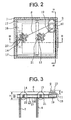
- the hoisting machine 9 is installed such that it lies astride the edge portion 17 of the hoisting machine assembly 15 and the hoisting machine auxiliary support base 18 and that the brake inspection access port 19 is positioned in the vertical projection surface of the hoisting machine 9 with respect to the base 16.
- the hoisting machine 9 is set such that the rotating surfaces of the sheave 10 are horizontal, the sheave 10 faces toward the ceiling side of the hoistway 1, and the motor 11 and the brake 12 face downward.
- the hoisting machine 9 is disposed at a corner near the hatch door 23 in the plan view of the hoistway 1.
- the hoisting machine 9 is a so-called thin type hoisting machine, which is thinner in the direction of the rotating axis.
- the thin type hoisting machine refers to a hoisting machine in which its thickness in the direction of the rotating axis is smaller than its thickness in the direction perpendicular to the direction of the rotating axis, or a hoisting machine that is sufficiently thin to be accommodated in the gap between the car 3 at the top floor level and the ceiling surface of the hoistway 1.
- the thin type hoisting machine is, for example, the one disclosed in Japanese Unexamined Patent Publication No. 12-289954 , and the detailed descriptions thereof will be omitted.
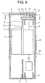
- the hoisting machine 9 is disposed such that the majority of the height of the hoisting machine 9 (height B in the drawing) is accommodated within the height of the first direction inverting pulley 13 and the second direction inverting pulley 14 (height A in the drawing).
- the motor of the hoisting machine 9 is disposed within the height A of the first direction inverting pulley 13 and the second direction inverting pulley 14 so as to minimize the total height of the height A of the first direction inverting pulley 13 and the second direction inverting pulley 14 and the height B of the hoisting machine 9.
- the height of the hoisting machine assembly 15 (height C in the drawing) is set such that it is accommodated within the height of the equipment directly mounted on the hoisting machine assembly 15, i.e., the height of the first direction inverting pulley 13 and the second direction inverting pulley 14 (height A in the drawing).
- the counterweight 6 is disposed to ascend and descend along the hoistway wall 2 opposing the hatch door 23.
- the elevator apparatus according to this example is a so-called "counterweight back drop system” in which the counterweight 6 is disposed at the side opposing the hatch door 23.
- the first direction inverting pulley 13 is rotatably supported by the two opposing sides of the first opening 21, a part of the first direction inverting pulley 13 projecting downward beyond the base 16.
- the second direction inverting pulley 14 is rotatably supported by the two opposing sides of the second opening 22, a part of the second direction inverting pulley 14 projecting downward beyond the base 16.
- the hoisting machine 9 is installed such that it lies astride the edged portion 17 of the hoisting machine assembly 15 and the hoisting machine auxiliary supporting base 18, and the brake inspection access port 19 is positioned in the vertical projection surface of the hoisting machine 9 on the surface of the base 16. Furthermore, the hoisting machine 9 is set so that the motor 11 and the brake 12 face downward. This allows the motor 11 and the brake 12 to be visually checked from the direction of an arrow D shown in Fig. 4 , and also permits maintenance work to be accomplished from the direction of the arrow D.
- a plurality of ropes are used for the main rope 8, and the ropes are installed between the first direction inverting pulley 13 and the sheave 10 of the hoisting machine 9 such that the ropes are wound at a fleet angle 20 with respect to each rope groove of the first direction inverting pulley 13 or the sheave 10, as shown in the drawing. If the fleet angle 20 is large, then the side surfaces of the rope grooves and the main rope 8 are brought into intense contact, leading to a shortened life of the main rope 8. For this reason, it is preferable to install the first direction inverting pulley 13 and the sheave 10 spaced away from each other as much as possible thereby to minimize the fleet angle 20.
- the hoisting machine 9 is disposed at the corner close to the hatch door 23 in the plan view of the hoistway 1. Furthermore, the counterweight 6 is disposed on the side opposing the hatch door 23 to maximize the distance between the hoisting machine 9 and the second direction inverting pulley 14.
- the relationship between the second direction inverting pulley 14 and the sheave 10 is the same as the relationship between the first direction inverting pulley 13 and the sheave 10, so the explanation thereof will be omitted.
- the elevator apparatus discussed above is constructed to have one to one roping, thus obviating the need for the two car bottom return sheaves 26 on the bottom surface of the car 3 and the counterweight suspension sheave 27 of the counterweight 6. This makes it possible to reduce the number of components and to simplify the construction accordingly. Hence, the flexibility of the layout in the hoistway can be improved.
- the one to one roping construction allows the length of the main rope 8 to be reduced with a resultant reduction in cost.
- the hoisting machine 9 is installed such that the sheave 10 is located above the motor 11 and the brake 12, allowing the majority of the height of the hoisting machine 9 to be accommodated within the height of the first direction inverting pulley 13 and the second direction inverting pulley 14 in the direction of the height of the hoistway 1.
- the overhead dimension dimension OH in Fig. 1
- the hoistway 1 permits space saving in the hoistway 1 to be achieved.
- the hoisting machine 9 is of the thin type hoisting machine having a thin structure, the overhead dimension (dimension OH in Fig. 1 ) can be decreased, allowing space saving in the hoistway 1 to be achieved.
- the hoisting machine 9 is installed such that the motor 11 and the brake 12 face downward, and the brake inspection access portion 19 is provided in the vertical projection surface of the hoisting machine 9, permitting easy maintenance and inspection of the hoisting machine 9 to be performed.
- the base 16 is supported by the car rail 4 or the counterweight rail 7, obviating the need for providing a separate member for supporting the base 16. This permits a cost reduction to be achieved.
- the base 16 is supported by the wall of the hoistway 1, obviating the need for providing a separate member for supporting the base 16. This permits a cost reduction to be achieved.
- the hoisting machine 9 is disposed to extend beyond the vertical projection surface of the car 3 in the plan view of the hoistway 1, so that the gap between the first direction inverting pulley 13 and the second direction inverting pulley 14 and the sheave 10 can be maximized, and the fleet angle 20 can be increased. This arrangement enables the life of the main rope 8 to be prolonged.
- reference numeral 15 denotes a hoisting machine assembly that is formed of a planar base 16 providing its bottom surface, edge portions 17 with their sides at both ends shaped like U, and a hoisting machine auxiliary potion 25 provided such that it projects from one longer side.
- the hoisting machine assembly 15 is supported at its both short sides by a hoistway wall 2, and adapted to install a first direction inverting pulley 13 to the base 16.
- the two short sides of the hoisting machine assembly 15 are fixed on the hoistway wall 2 at the side where a hatch door 23 is installed and at a side opposing the side where the hatch door 23 is installed.
- Reference numeral 18 denotes a hoisting machine auxiliary supporting base secured to the hoistway wall 2 such that it is parallel to the edge portions 17 of the hoisting machine assembly 15 at the side of the hoistway wall 2 that opposes the hoisting machine auxiliary portion 25.
- a hoisting machine 9 is installed astride the edge portions 17 of the hoisting machine assembly 15 and the hoisting machine auxiliary support base 18, and is disposed at a corner close to the hatch door 23 in the plan view of the hoistway 1.
- the hoisting machine 9 is installed such that the rotating surfaces of a sheave 10 are horizontal and the sheave 10 faces the ceiling side of the hoistway 1, while a motor 11 and a brake 12 face downward.
- the hoisting machine 9 is disposed at a corner close to the hatch door 23 in the plan view of the hoistway 1.
- a pair of counterweight rails 7 is installed along the hoistway wall 2 at the side where the hoisting machine auxiliary support base 18 is installed in the plan view of the hoistway 1. More specifically, the counterweight 6 is adapted to ascend and descend along the hoistway wall 2 at the side where the hoisting machine auxiliary support base 18 is installed in the plan view of the hoistway 1, which represents a so-called "counterweight side drop system.”
- One of the counterweight rails 7 is disposed at the corner opposing the hatch door 23 in the plan view of the hoistway 1 so as to provide a maximum distance between the second direction inverting pulley 14 and the sheave 10 of the hoisting machine 9. The reason for this is as discussed in Example 1, i.e., to minimize the fleet angle 20.
- the second direction inverting pulley 14 lies astride the hoisting machine auxiliary portion 25 of the hoisting machine assembly 15 and the hoisting machine auxiliary supporting base 18, and is disposed at the top portion of the hoistway 1 in the ascending/descending direction of the counterweight 6.
- the first direction inverting pulley 13 is installed on the base 16 in the same manner as that in Example 1.
- Fig. 8 will be used for the explanation.
- the hoisting machine 9 is installed such that it lies astride the edged portions 17 of the hoisting machine assembly 15 and the hoisting machine auxiliary supporting base 18. Furthermore, the hoisting machine 9 is installed such that the motor 11 and the brake 12 face downward. This allows the motor 11 and the brake 12 to be visually checked from the direction of an arrow E shown in Fig. 8 , and also permits maintenance work to be accomplished from the direction of the arrow E.
- the elevator apparatus discussed above has the counterweight side drop system and also the one to one roping, so that it provides the advantage similar to that of Example 1 in the counterweight side drop system.
- the hoisting machine 9 is installed such that the motor 11 and the brake 12 face downward, and the hoisting machine 9 is installed such that it lies astride the edge portions 17 of the hoisting machine assembly 15 and the hoisting machine auxiliary supporting base 18; therefore, the maintenance and inspection of the hoisting machine 9 can be easily accomplished without providing the brake inspection access port 19 in the example.
- An elevator apparatus according to another example to which the present invention is applied, especially an elevator apparatus of the counterweight side drop system in which the angle of winding of a main rope onto a sheave is larger than that in the elevator apparatus in Example 2, will be explained in conjunction with Fig. 9 to Fig. 10 .
- the components assigned the like reference numerals as those in Example 1 will denote the like or equivalent components.
- Example 2 differs from Example 1 only in the disposition of a counterweight 6 and counterweight rails 7; hence, the descriptions will be given only of this different aspect.
- the two surfaces of a hoistway wall 2 that are in contact with the side where a hatch door 23 is installed in the plan view of the hoistway 1 will be referred to as side surfaces.
- a hoisting machine 9 is installed at one side surface of a hoistway wall 2.
- a counterweight 6 and counterweight rails 7 are disposed in contact with the other side surface of the hoistway wall 2, and between a car rail 4 and the side of the hoistway wall 2 at which the hatch door 23 is installed.
- a second direction inverting pulley 14 is installed at a different position from that in Example 1; it is installed above a counterweight 6 at the top portion of the hoistway 1.
- a hoisting machine assembly 15 is supported by the car rail 4 and the counterweight rails 7.
- the hoisting machine 9 installed on a hoisting machine assembly 15, the first direction inverting pulley 13 and a second direction inverting pulley 14 are concentrated substantially in the half surface adjacent to the hatch door 23 in the plan view of the hoistway 1. This arrangement has reduced the size of the hoisting machine assembly 15 substantially to the half of that of Example 1.
- the procedure for installing the hoisting machine 9, the first direction inverting pulley 13, and the second direction inverting pulley 14 on the hoisting machine assembly 15 is the same as that in Example 1.
- the angle of winding of the main rope 8 onto the sheave 10 is larger than that in Example 2, allowing the tractive capability of the sheave 10 to be enhanced.
- the angle of winding of the main rope 8 onto the sheave 10 depends upon the shapes of the plan views of the car 3 and the hoistway 1, so that the angle in Example 2 or in this example may be selected, whichever is better suited, depending on the condition under which the elevator apparatus is installed.
- the elevator apparatus discussed above permits the advantages similar to those of Example 1 to be obtained. Moreover, the angle of winding of the main rope 8 onto the sheave 10 can be increased, as necessary, so that the tractive capability of the sheave 10 can be improved.
- the area of the base 16 can be reduced, making it possible to cut down cost.
- the elevator apparatus is equipped with a car that ascends and descends along a car rail provided in a hoistway, a counterweight that ascends and descends along a counterweight rail provided in the hoistway, a hoisting machine that has a sheave, a motor for driving the sheave, and a brake for controlling the motor, and is disposed at the top portion of the hoistway such that a rotating surface of the sheave is horizontal, first and second direction inverting pulleys disposed at the top portion of the hoistway, and a main rope that has one end thereof connected to the car, while the other end thereof connected to the counterweight, and is wound onto the first and second direction inverting pulleys and the sheave to suspend the car and the counterweight.
- space saving in the hoistway can be achieved.
- the thickness of the hoisting machine in the direction of the rotating axis is smaller than the thickness in the direction perpendicular to the direction of the rotating axis, thus permitting space saving in the hoistway to be achieved.
- the elevator apparatus is further equipped with a hoisting machine assembly which is installed at the top portion of the hoistway and on which the hoisting machine and the first and second direction inverting pulleys are mounted. This arrangement makes it possible to save space in the hoistway.
- the hoisting machine assembly is supported by the car rail or the counterweight rail, obviating the need for providing a separate member for supporting the hoisting machine assembly.
- the hoisting machine assembly is supported by the wall of the hoistway, obviating the need for providing a separate member for supporting the hoisting machine assembly.
- the hoisting machine assembly is positioned such that its height is within the height of the first direction inverting pulley or the second direction inverting pulley in the direction of the height of the hoistway. Thus, space in the hoistway can be saved.
- the hoisting machine is disposed at a corner in the plan view of the hoistway, making it possible to maintain a large gap between the first direction inverting pulley or the second direction inverting pulley and the sheave.
- the hoisting machine is disposed at a corner in the plan view of the hoistway such that it extends beyond the vertical projection surface of the car in the plan view of the hoistway. This makes it possible to maintain a large gap between the first direction inverting pulley or the second direction inverting pulley and the sheave.
- the hoisting machine is disposed such that the brake is positioned at the lower side in the hoistway, permitting maintenance and inspection to be easily carried out.
- the hoisting machine is disposed on the top surface of the hoisting machine assembly such that the brake faces the lower end of the hoistway, and the hoisting machine assembly is equipped with an inspection access port provided to penetrate the vertical projection surface of the hosting machine. This permits easy maintenance and inspection.
- the present invention relates to a machine-room-less elevator apparatus with no machine room.
Landscapes
- Engineering & Computer Science (AREA)
- Civil Engineering (AREA)
- Mechanical Engineering (AREA)
- Structural Engineering (AREA)
- Lift-Guide Devices, And Elevator Ropes And Cables (AREA)
- Cage And Drive Apparatuses For Elevators (AREA)
Abstract
Claims (9)
- Appareil d'ascenseur comprenant :une cabine (3) qui monte et qui descend le long d'un rail de cabine (4) prévu dans une cage d'ascenseur (1) ;un contrepoids (6) qui monte et qui descend le long d'un rail de contrepoids (7) prévu dans la cage d'ascenseur (1) ;une machine de levage (9) qui a un réa (10), un moteur (11) pour entraîner le réa (10), et un frein (12) pour commander le moteur (11), et qui est disposée au niveau de la partie supérieure de la cage d'ascenseur (1) afin qu'une surface de rotation du réa (10) soit horizontale ;des première et deuxième poulies (13, 14) d'inversion de direction disposées au niveau de la partie supérieure de la cage d'ascenseur (1) ;un câble principal (8) dont une extrémité est reliée à la cabine (3), tandis que l'autre extrémité est reliée au contrepoids (6), et enroulé sur les première et deuxième poulies (13, 14) d'inversion de direction et le réa (10) pour suspendre la cabine (3) et le contrepoids (6) ; caractérisé parun assemblage (15) de machine de levage construit avec une base plane (16) servant de surface de fond et d'une partie de bord (17) avec les deux extrémités en forme en U, supporté par le rail de cabine (4) et le rail de contrepoids (7), et sur lequel la machine de levage (9) et la première poulie (13) d'inversion de direction et la deuxième poulie (14) d'inversion de direction sont installées ; etune base de support auxiliaire (18) de machine de levage installée à un coin sur une surface de la base (16) afin d'être parallèle à une partie de bord (17) de l'assemblage (15) de machine de levage, ladite machine de levage (9) étant montée à califourchon sur les parties de bord (17) de l'assemblage (15) de machine de levage et la base de support auxiliaire (18) de machine de levage.
- Appareil d'ascenseur comprenant :une cabine (3) qui monte et qui descend le long d'un rail de cabine (4) prévu dans une cage d'ascenseur (1) ;un contrepoids (6) qui monte et qui descend le long d'un rail de contrepoids (7) prévu dans la cage d'ascenseur (1) ;une machine de levage (9) qui a un réa (10), un moteur (11) pour entraîner le réa (10), et un frein (12) pour commander le moteur (11), et qui est disposée au niveau de la partie supérieure dans la cage d'ascenseur (1) afin qu'une surface de rotation du réa (10) soit horizontale ;des première et deuxième poulies (13, 14) d'inversion de direction disposées au niveau de la partie supérieure de la cage d'ascenseur (1) ;un câble principal (8) dont une extrémité est reliée à la cabine (3), tandis que l'autre est reliée au contrepoids (6), et est enroulé sur les première et deuxième poulies (13, 14) d'inversion de direction et le réa (10) pour suspendre la cabine (3) et le contrepoids (6) ; caractérisé en ce queun assemblage (15) de machine de levage formé d'une base plane (16) fournissant sa surface de fond, des parties de bord (17) avec leurs côtés aux deux extrémités en forme de U, et une partie auxiliaire (25) de machine de levage prévue afin de faire saillie d'un côté plus long, l'assemblage (15) de machine de levage étant supporté au niveau de ses deux côtés courts par une paroi (2) de cage d'ascenseur et adapté pour installer une première poulie (13) d'inversion de direction à la base (16) ; etune base de support auxiliaire (18) de machine de levage fixée à la paroi (2) de cage d'ascenseur afin d'être parallèle aux parties de bord (17) de l'assemblage (15) de machine de levage du côté de la paroi (2) de cage d'ascenseur qui s'oppose à la partie auxiliaire (25) de machine de levage, ladite machine de levage (9) étant montée à califourchon sur les parties de bord (17) de l'assemblage (15) de machine de levage et la base de support auxiliaire (18) de machine de levage.
- Appareil d'ascenseur selon la revendication 1 ou 2, dans lequel l'épaisseur de la machine de levage (9) dans la direction de l'axe de rotation est plus petite que l'épaisseur dans la direction perpendiculaire à la direction de l'axe de rotation.
- Appareil d'ascenseur selon l'une quelconque des revendications 1 à 3, dans lequel l'assemblage (15) de machine de levage est installé au niveau de la partie supérieure de la cage d'ascenseur (1).
- Appareil d'ascenseur selon l'une quelconque des revendications 1 à 4, dans lequel l'assemblage (15) de machine de levage est positionné afin que sa hauteur soit dans la hauteur de la première ou la deuxième (13, 14) poulie d'inversion de direction dans la direction de la hauteur de la cage d'ascenseur (1)
- Appareil d'ascenseur selon l'une quelconque des revendications 1 à 5, dans lequel la machine de levage (9) est disposée à un coin dans la vue en plan de la cage d'ascenseur (1).
- Appareil d'ascenseur selon l'une quelconque des revendications 1 à 5, dans lequel la machine de levage (9) est disposée à un coin dans la vue en plan de la cage d'ascenseur (1) afin de s'étendre au-delà de la surface de projection verticale de la cabine (3) dans la vue en plan de la cage d'ascenseur (1).
- Appareil d'ascenseur selon l'une quelconque des revendications 1 à 7, dans lequel la machine de levage (9) est disposée afin que le frein (12) soit positionné du côté inférieur de la cage d'ascenseur (1).
- Appareil d'ascenseur selon l'une quelconque des revendications 1 à 7, dans lequel
la machine de levage (9) est disposée sur la surface supérieure de l'assemblage (15) de machine de levage afin que le frein (12) soit en face de l'extrémité inférieure de la cage d'ascenseur (1) ; et
l'assemblage (15) de machine de levage est équipé d'un orifice (19) d'accès d'inspection prévu pour pénétrer la surface de projection verticale de la machine de levage (9).
Applications Claiming Priority (1)
| Application Number | Priority Date | Filing Date | Title |
|---|---|---|---|
| PCT/JP2001/004685 WO2002098782A1 (fr) | 2001-06-04 | 2001-06-04 | Dispositif ascenseur |
Publications (3)
| Publication Number | Publication Date |
|---|---|
| EP1396457A1 EP1396457A1 (fr) | 2004-03-10 |
| EP1396457A4 EP1396457A4 (fr) | 2010-02-17 |
| EP1396457B1 true EP1396457B1 (fr) | 2012-07-25 |
Family
ID=11737395
Family Applications (1)
| Application Number | Title | Priority Date | Filing Date |
|---|---|---|---|
| EP01934514A Expired - Lifetime EP1396457B1 (fr) | 2001-06-04 | 2001-06-04 | Dispositif ascenseur |
Country Status (5)
| Country | Link |
|---|---|
| EP (1) | EP1396457B1 (fr) |
| JP (1) | JP4934941B2 (fr) |
| KR (1) | KR20030020969A (fr) |
| CN (1) | CN1302979C (fr) |
| WO (1) | WO2002098782A1 (fr) |
Families Citing this family (12)
| Publication number | Priority date | Publication date | Assignee | Title |
|---|---|---|---|---|
| CN1592712A (zh) * | 2002-12-04 | 2005-03-09 | 三菱电机株式会社 | 电梯装置 |
| JP2006513950A (ja) | 2003-01-31 | 2006-04-27 | オーチス エレベータ カンパニー | エレベータ機械、綱車及び終端部のための一体型支持体 |
| ATE509034T1 (de) * | 2003-10-07 | 2011-05-15 | Yeda Res & Dev | Antikörper gegen nik, deren herstellung und verwendung |
| EP1693328B1 (fr) * | 2003-12-09 | 2013-04-24 | Mitsubishi Denki Kabushiki Kaisha | Dispositif elevateur |
| EP1710196B1 (fr) * | 2004-01-27 | 2012-08-08 | Mitsubishi Denki Kabushiki Kaisha | Unite d'entrainement d'un appareil ascenseur, appareil ascenseur, son procede d'installation, et son procede de maintenance /d'inspection |
| CN101143677B (zh) * | 2004-04-14 | 2010-06-09 | 三菱电机株式会社 | 电梯装置 |
| EP1930283A4 (fr) * | 2005-09-30 | 2012-01-18 | Mitsubishi Electric Corp | Dispositif d'ascenseur |
| JP5078998B2 (ja) * | 2007-06-01 | 2012-11-21 | 三菱電機株式会社 | エレベータ装置 |
| KR101225035B1 (ko) * | 2008-12-05 | 2013-01-22 | 오티스 엘리베이터 컴파니 | 엘리베이터 기계 지지체에 지지된 제어 전자기기를 포함한 엘리베이터 시스템 |
| WO2011072113A1 (fr) * | 2009-12-09 | 2011-06-16 | Thyssenkrupp Elevator Capital Corporation | Appareil ascenseur ne donnant pas de flexion inversée de câble |
| FI125130B (fi) * | 2012-01-27 | 2015-06-15 | Kone Corp | Laitteisto hissin nostokoneiston kiinnittämiseksi ja kiinnitysjärjestely |
| CN104058316A (zh) * | 2014-06-30 | 2014-09-24 | 苏州富士电梯有限公司 | 一种贯通门电梯布置结构 |
Family Cites Families (7)
| Publication number | Priority date | Publication date | Assignee | Title |
|---|---|---|---|---|
| FI96302C (fi) * | 1992-04-14 | 1996-06-10 | Kone Oy | Vetopyörähissi |
| JP3148610B2 (ja) * | 1995-12-11 | 2001-03-19 | 三菱電機株式会社 | エレベータ装置 |
| ES2227012T3 (es) | 1996-11-11 | 2005-04-01 | Inventio Ag | Instalacion de ascensor con unidad motriz dispuesta en la caja de ascensor. |
| JP4191331B2 (ja) | 1999-01-08 | 2008-12-03 | 三菱電機株式会社 | エレベーター装置 |
| JP3961718B2 (ja) * | 1999-06-09 | 2007-08-22 | 株式会社日立製作所 | 機械室レスエレベータ |
| JP4404999B2 (ja) * | 1999-08-16 | 2010-01-27 | 三菱電機株式会社 | エレベータ装置 |
| JP4191333B2 (ja) * | 1999-08-26 | 2008-12-03 | 三菱電機株式会社 | エレベーター巻上機 |
-
2001
- 2001-06-04 KR KR10-2003-7001615A patent/KR20030020969A/ko active Search and Examination
- 2001-06-04 CN CNB018123147A patent/CN1302979C/zh not_active Expired - Fee Related
- 2001-06-04 WO PCT/JP2001/004685 patent/WO2002098782A1/fr not_active Application Discontinuation
- 2001-06-04 EP EP01934514A patent/EP1396457B1/fr not_active Expired - Lifetime
- 2001-06-04 JP JP2002568879A patent/JP4934941B2/ja not_active Expired - Fee Related
Also Published As
| Publication number | Publication date |
|---|---|
| WO2002098782A1 (fr) | 2002-12-12 |
| JP4934941B2 (ja) | 2012-05-23 |
| CN1457315A (zh) | 2003-11-19 |
| EP1396457A4 (fr) | 2010-02-17 |
| JPWO2002098782A1 (ja) | 2004-09-16 |
| CN1302979C (zh) | 2007-03-07 |
| KR20030020969A (ko) | 2003-03-10 |
| EP1396457A1 (fr) | 2004-03-10 |
Similar Documents
| Publication | Publication Date | Title |
|---|---|---|
| KR100618467B1 (ko) | 엘리베이터 장치 | |
| JP2000247560A (ja) | エレベーター装置 | |
| US6619433B1 (en) | Elevator system using minimal building space | |
| EP1302430B1 (fr) | Dispositif d'ascenseur | |
| EP1396457B1 (fr) | Dispositif ascenseur | |
| EP1319627B1 (fr) | Dispositif d'ascenseur | |
| JP4255523B2 (ja) | エレベーター | |
| EP1481935A1 (fr) | Ascenseur | |
| EP1327596B1 (fr) | Dispositif d'ascenseur | |
| EP1431231B1 (fr) | Ascenseur sans local de machinerie | |
| KR100415749B1 (ko) | 엘리베이터 장치 | |
| EP1057769B1 (fr) | Ascenseur | |
| EP1512652B1 (fr) | Ascenseur | |
| EP1724229A1 (fr) | Appareil elevateur | |
| JP2000344450A (ja) | エレベーター装置 | |
| EP1586525B1 (fr) | Equipement monte-charge | |
| EP1314680B1 (fr) | Dispositif d'ascenseur | |
| EP1736431B1 (fr) | Appareillage d'ascenseur | |
| JP4091218B2 (ja) | エレベータ | |
| KR100804886B1 (ko) | 엘리베이터 장치 | |
| KR100804887B1 (ko) | 엘리베이터 장치 | |
| KR20050084529A (ko) | 엘리베이터 장치 | |
| KR20060036042A (ko) | 엘리베이터 장치 | |
| JP2005231869A (ja) | エレベータ装置 |
Legal Events
| Date | Code | Title | Description |
|---|---|---|---|
| PUAI | Public reference made under article 153(3) epc to a published international application that has entered the european phase |
Free format text: ORIGINAL CODE: 0009012 |
|
| 17P | Request for examination filed |
Effective date: 20030115 |
|
| AK | Designated contracting states |
Kind code of ref document: A1 Designated state(s): AT BE CH CY DE DK ES FI FR GB GR IE IT LI LU MC NL PT SE TR |
|
| AX | Request for extension of the european patent |
Extension state: AL LT LV MK RO SI |
|
| RAP1 | Party data changed (applicant data changed or rights of an application transferred) |
Owner name: MITSUBISHI DENKI KABUSHIKI KAISHA |
|
| A4 | Supplementary search report drawn up and despatched |
Effective date: 20100119 |
|
| 17Q | First examination report despatched |
Effective date: 20100427 |
|
| GRAP | Despatch of communication of intention to grant a patent |
Free format text: ORIGINAL CODE: EPIDOSNIGR1 |
|
| GRAS | Grant fee paid |
Free format text: ORIGINAL CODE: EPIDOSNIGR3 |
|
| GRAA | (expected) grant |
Free format text: ORIGINAL CODE: 0009210 |
|
| STAA | Information on the status of an ep patent application or granted ep patent |
Free format text: STATUS: THE PATENT HAS BEEN GRANTED |
|
| AK | Designated contracting states |
Kind code of ref document: B1 Designated state(s): DE NL |
|
| REG | Reference to a national code |
Ref country code: DE Ref legal event code: R096 Ref document number: 60146864 Country of ref document: DE Effective date: 20120920 |
|
| REG | Reference to a national code |
Ref country code: NL Ref legal event code: VDEP Effective date: 20120725 |
|
| PG25 | Lapsed in a contracting state [announced via postgrant information from national office to epo] |
Ref country code: NL Free format text: LAPSE BECAUSE OF FAILURE TO SUBMIT A TRANSLATION OF THE DESCRIPTION OR TO PAY THE FEE WITHIN THE PRESCRIBED TIME-LIMIT Effective date: 20120725 |
|
| PLBE | No opposition filed within time limit |
Free format text: ORIGINAL CODE: 0009261 |
|
| STAA | Information on the status of an ep patent application or granted ep patent |
Free format text: STATUS: NO OPPOSITION FILED WITHIN TIME LIMIT |
|
| 26N | No opposition filed |
Effective date: 20130426 |
|
| REG | Reference to a national code |
Ref country code: DE Ref legal event code: R097 Ref document number: 60146864 Country of ref document: DE Effective date: 20130426 |
|
| REG | Reference to a national code |
Ref country code: DE Ref legal event code: R084 Ref document number: 60146864 Country of ref document: DE |
|
| REG | Reference to a national code |
Ref country code: DE Ref legal event code: R084 Ref document number: 60146864 Country of ref document: DE Effective date: 20141107 |
|
| PGFP | Annual fee paid to national office [announced via postgrant information from national office to epo] |
Ref country code: DE Payment date: 20150527 Year of fee payment: 15 |
|
| REG | Reference to a national code |
Ref country code: DE Ref legal event code: R119 Ref document number: 60146864 Country of ref document: DE |
|
| PG25 | Lapsed in a contracting state [announced via postgrant information from national office to epo] |
Ref country code: DE Free format text: LAPSE BECAUSE OF NON-PAYMENT OF DUE FEES Effective date: 20170103 |