EP1396345B1 - Méthode, système et appareil d'impression à jet d'encre, méthode et programme de génération de données d'impression, et pilote d'imprimante - Google Patents
Méthode, système et appareil d'impression à jet d'encre, méthode et programme de génération de données d'impression, et pilote d'imprimante Download PDFInfo
- Publication number
- EP1396345B1 EP1396345B1 EP03020286A EP03020286A EP1396345B1 EP 1396345 B1 EP1396345 B1 EP 1396345B1 EP 03020286 A EP03020286 A EP 03020286A EP 03020286 A EP03020286 A EP 03020286A EP 1396345 B1 EP1396345 B1 EP 1396345B1
- Authority
- EP
- European Patent Office
- Prior art keywords
- ink
- printing
- mode
- volume
- jet
- Prior art date
- Legal status (The legal status is an assumption and is not a legal conclusion. Google has not performed a legal analysis and makes no representation as to the accuracy of the status listed.)
- Expired - Lifetime
Links
Images


Classifications
-
- B—PERFORMING OPERATIONS; TRANSPORTING
- B41—PRINTING; LINING MACHINES; TYPEWRITERS; STAMPS
- B41J—TYPEWRITERS; SELECTIVE PRINTING MECHANISMS, i.e. MECHANISMS PRINTING OTHERWISE THAN FROM A FORME; CORRECTION OF TYPOGRAPHICAL ERRORS
- B41J2/00—Typewriters or selective printing mechanisms characterised by the printing or marking process for which they are designed
- B41J2/005—Typewriters or selective printing mechanisms characterised by the printing or marking process for which they are designed characterised by bringing liquid or particles selectively into contact with a printing material
- B41J2/01—Ink jet
- B41J2/205—Ink jet for printing a discrete number of tones
-
- B—PERFORMING OPERATIONS; TRANSPORTING
- B41—PRINTING; LINING MACHINES; TYPEWRITERS; STAMPS
- B41J—TYPEWRITERS; SELECTIVE PRINTING MECHANISMS, i.e. MECHANISMS PRINTING OTHERWISE THAN FROM A FORME; CORRECTION OF TYPOGRAPHICAL ERRORS
- B41J2/00—Typewriters or selective printing mechanisms characterised by the printing or marking process for which they are designed
- B41J2/005—Typewriters or selective printing mechanisms characterised by the printing or marking process for which they are designed characterised by bringing liquid or particles selectively into contact with a printing material
- B41J2/01—Ink jet
- B41J2/21—Ink jet for multi-colour printing
- B41J2/2121—Ink jet for multi-colour printing characterised by dot size, e.g. combinations of printed dots of different diameter
- B41J2/2125—Ink jet for multi-colour printing characterised by dot size, e.g. combinations of printed dots of different diameter by means of nozzle diameter selection
-
- B—PERFORMING OPERATIONS; TRANSPORTING
- B41—PRINTING; LINING MACHINES; TYPEWRITERS; STAMPS
- B41J—TYPEWRITERS; SELECTIVE PRINTING MECHANISMS, i.e. MECHANISMS PRINTING OTHERWISE THAN FROM A FORME; CORRECTION OF TYPOGRAPHICAL ERRORS
- B41J2/00—Typewriters or selective printing mechanisms characterised by the printing or marking process for which they are designed
- B41J2/005—Typewriters or selective printing mechanisms characterised by the printing or marking process for which they are designed characterised by bringing liquid or particles selectively into contact with a printing material
- B41J2/01—Ink jet
- B41J2/21—Ink jet for multi-colour printing
- B41J2/2121—Ink jet for multi-colour printing characterised by dot size, e.g. combinations of printed dots of different diameter
- B41J2/2128—Ink jet for multi-colour printing characterised by dot size, e.g. combinations of printed dots of different diameter by means of energy modulation
-
- B—PERFORMING OPERATIONS; TRANSPORTING
- B41—PRINTING; LINING MACHINES; TYPEWRITERS; STAMPS
- B41J—TYPEWRITERS; SELECTIVE PRINTING MECHANISMS, i.e. MECHANISMS PRINTING OTHERWISE THAN FROM A FORME; CORRECTION OF TYPOGRAPHICAL ERRORS
- B41J23/00—Power drives for actions or mechanisms
Definitions
- This invention relates to an ink-jet printing method, a printing system, an ink-jet printing apparatus, a print data generating method, a program and a printer driver. More particularly, the invention relates to generation of print data for being printed by an ink-jet printing apparatus, which has a first mode for high-speed printing and a second mode for high-quality printing, in which printing is performed by scanning a carriage over a print medium, the carriage mounting an ink-jet printhead provided with orifices for discharging ink droplets of a first volume and orifices for discharging ink droplets of a second volume smaller than the first volume.
- Printers for printing desired information such as text and images on a sheet-like print medium such as paper or film are in wide use as information printing devices in word processors, personal computers and facsimile machines, etc.
- serial printing is in wide use generally owing to low cost and compactness.
- the apparatus is equipped with a mounted printhead that discharged ink in accordance with desired print information and printing is carried out while the printhead is scanned back and forth in a direction that intersects the direction in which the print medium is fed.
- a method of discharging ink droplets of different volumes from the same nozzle has been proposed as a method of obtaining different volumes of discharged ink (e.g., see the specification of Japanese Patent No. 3058493).
- this method it is known to provide two or more types of heaters of different sizes in a case where the ink droplets are discharged utilizing thermal energy, or to control voltage, which is applied to a piezoelectric element, in several stages in a case where the ink droplets are discharged by compressing an ink chamber using the piezoelectric element.
- an advantage is that the quality of the printed image is improved.
- the same pixel can be printed using different nozzle rows in a single scan. This means that even if multiple-pass printing is not carried out, one pixel is printed by a plurality of ink droplets discharged from different nozzles, and therefore the effects of differences in individual nozzles are mitigated, thereby reducing stripes and unevenness and improving image quality.
- ink-jet printers that carry out high-quality printing are believed to be advantageous in terms of the structure having a plurality of nozzle rows that discharge ink droplets of different volumes.
- Fig. 2 is a diagram in which an ink-jet printhead unit is seen from a printed surface, the unit having two nozzle rows per color for discharging ink droplets of different volumes.
- one printhead is provided with one nozzle row.
- printheads are disposed in the following order: a printhead 11C for discharging cyan (C) ink droplets of large volume, a printhead 11sc for discharging cyan (sc) ink droplets of small volume, a printhead 11M for discharging magenta (M) ink droplets of large volume, a printhead 11sm for discharging magenta (sm) ink droplets of small volume, a printhead 11Y for discharging yellow (Y) ink droplets of large volume, and a printhead 11sy for discharging yellow (sy) ink droplets of small volume.
- Each printhead has 128 nozzles at a pitch of 600 dpi.
- the printheads 11C, 11M, 11Y discharge ink droplets of approximately 5 ng as ink droplets of large volume (dots of large size), and the printheads 11sc, 11sm, 11sy discharge ink droplets of approximately 2 ng as ink droplets of small volume (dots of small size).
- a printhead that discharges large dots and a printhead that discharges small dots of the same color are arranged next to each other.
- the reason for this is that when two printheads using the same color ink are arranged next to each other, an advantage gained is that a common ink tank can be employed for these two printheads, thereby making it possible to simplify the passageway from the ink tank to the printhead.
- Fig. 10 is a schematic view illustrating printing in progress as seen from the side. Here only the cyan printheads are shown in order to simplify the description.
- a printhead unit 5 is provided with the printhead 11C that discharges large dots Cd and the printhead 11sc that discharges small dots scd.
- the ink droplets are discharged toward printing paper 7 in accordance with an image signal while a carriage is being moved in the direction of the arrow.
- the discharged ink droplets Since the ink droplets are discharged while the carriage is moving, the discharged ink droplets have a velocity component in the traveling direction of the carriage. As a consequence, the ink droplets are subjected to the effects of air currents and this has an effect upon ink impact position.
- the small dots scd also are affected by turbulence produced by the large dots Cd discharged from the neighboring printhead 11C. This makes it difficult to control the impact position. As a result, a disturbance is produced in the impact position of the small dots, this disturbance in impact position appears as stripes and unevenness in the printed image and causes a decline in the quality of the printed image. The larger the number of large dots discharged, the more pronounced this phenomenon becomes.
- US 5,745,131 discloses a printing system employing ink droplets of a large volume and a small volume. This printing system is further able to be applied to a draft mode.
- US 5,198,833 describes a printing system where a print is conducted employing only a small number of ink droplets having a large volume in a draft mode, and is conducted employing only a relatively large number of ink droplets having a small volume.
- ink droplets having the large volume and ink droplets having the small volume are not employed simultaneously in the draft mode and in the fine mode.
- a high-density area is printed upon making the number of small dots used comparatively small or without using any small dots at all.
- the occurrence of stripes or unevenness in high-density areas can thus be suppressed, enabling printing to be performed at high speed with no decline in image quality.
- a high-density area is printed upon making the number of small dots used comparatively large, thereby making it possible to print an image having a high tonality and, at the same time, to suppress the occurrence of stripes and unevenness by using a plurality of printheads.
- print is not only to form significant information such as characters and graphics, but also to form, e.g., images, figures, and patterns on printing media in a broad sense, regardless of whether the information formed is significant or insignificant or whether the information formed is visualized so that a human can visually perceive it, or to process printing media.
- Print media are any media capable of receiving ink, such as cloth, plastic films, metal plates, glass, ceramics, wood, and leather, as well as paper sheets used in common printing apparatuses.
- ink (to be also referred to as a “liquid” hereinafter) should be broadly interpreted like the definition of "print” described above. That is, ink is a liquid which is applied onto a printing medium and thereby can be used to form images, figures, and patterns, to process the printing medium, or to process ink (e.g., to solidify or insolubilize a colorant in ink applied to a printing medium).
- a first embodiment of the present invention is a printing system comprising an ink-jet printer and a host computer.
- Fig. 1 is an external perspective view illustrating the structure of the ink-jet printer of this embodiment.
- Reference numeral 1 denotes a print medium (print sheet) such as a sheet of paper or plastic.
- a plurality of the sheets 1 stacked in a cassette or the like are supplied one sheet at a time by feed rollers (not shown).
- the supplied print sheet 1 is transported in the direction of arrow A by first and second transport roller pairs 3 and 4, respectively, spaced apart at fixed intervals and driven by respective ones of transport motors (not shown).
- Reference numeral 5 denotes a printhead unit having ink-jet printheads, which are for printing on the print sheet 1, and ink tanks. Inks contained in a black (K) ink tank 5a, cyan (C) ink tank 5b, magenta (M) ink tank 5c and yellow (Y) ink tank 5d are supplied to printheads (not shown) disposed in a plane facing the print sheet 1 and are discharged from the nozzles of each of the printheads in accordance with an image signal.
- the printhead unit 5 is mounted on a carriage 6, and a carriage motor 10 is coupled to the carriage 6 via a belt 7 and pulleys 8a, 8b. Accordingly, it is so arranged that the carriage 6 is scanned back and forth along a guide shaft 9 by driving the carriage motor 10.
- an image is printed by discharging ink toward the print sheet 1 in accordance with an image signal while the printhead unit 5 is moved in the direction of arrow B.
- the printhead unit 5 is returned to a home position to have clogged nozzles unclogged by a recovery unit 2.
- the print sheet 1 is transported in the direction of arrow A over a distance that conforms to the setting of a printing mode (described later) by driving the transport roller pairs 3, 4 by their transport motors.
- a desired image is printed on the print sheet 1 by repeating the above operation.
- the structure of the printhead unit 5 in this embodiment is similar to that shown in Fig. 2 described above, and the volumes of the ink droplets discharged from each of the printhead are similar to that of Fig. 2. That is, the printhead unit 5 is equipped with two printheads, one for large dots and one for small dots, for each of the colors cyan (C), magenta (M) and yellow (Y).
- the ink-jet printhead of this embodiment also has printheads for discharging black (K) ink, as has been described in connection with Fig. 1.
- K black
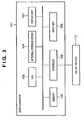
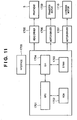
- Fig. 11 is a block diagram showing the arrangement of a control circuit of the ink-jet printer.
- reference numeral 1700 denotes an interface for inputting a print signal from an external unit such as a host computer; 1701, an MPU; 1702, a ROM for storing a control program (including character fonts if necessary) executed by the MPU 1701; and 1703, a DRAM for storing various data (the print signal, print data supplied to the printing head and the like).
- Reference numeral 1704 denotes a gate array (G. A.) for performing supply control of print data to the printhead unit 5. The gate array 1704 also performs data transfer control among the interface 1700, the MPU 1701, and the RAM 1703.
- Reference numeral 1710 denotes a carrier motor for transferring the printhead 5 in the main scanning direction; and 1709, a transfer motor for transferring a paper sheet.
- Reference numeral 1705 denotes a head driver for driving the printhead unit; and 1706 and 1707, motor drivers for driving the transfer motor 1709 and the carrier motor 1710.
- the print signal is converted into print data for a printing operation between the gate array 1704 and the MPU 1701.
- the motor drivers 1706 and 1707 are driven, and the printhead unit is driven in accordance with the print data supplied to the head driver 1705, thus performing the printing operation.
- control program executed by the MPU 1701 is stored in the ROM 1702, an arrangement can be adopted in which a writable storage medium such as an EEPROM is additionally provided so that the control program can be altered from a host computer connected to the ink-jet printer.
- a writable storage medium such as an EEPROM
- Fig. 3 is a block diagram illustrating the structure of a host computer 101 according to the first embodiment for outputting print data to the ink-jet printer described above.
- the host computer 101 in Fig. 3 includes a CPU 102 for exercising overall control; a memory 103 for storing a program and used as a work area; an external storage device 104 such as a floppy-disk drive or CD-ROM drive; an input unit 105 such as a keyboard and mouse operated by a user; an interface 106 for interfacing a printer; and a display unit 107 for displaying user information to the user.
- the CPU 102 executes a program that has been stored in the memory 103, thereby executing image processing such as color processing and quantization processing, described later.
- This program may be stored in the external storage device 104 or may be supplied from an external unit, not shown.
- the host computer 101 is connected to an ink-jet printer 110 via the interface 106, and printing is performed upon transmitting print data, which has undergone image processing, to the ink-jet printer 110.
- Fig. 4 is a block diagram for describing image processing executed by the host computer of this embodiment. This flowchart illustrates the processing flow for outputting applied image data, which is composed of eight bits for each of the colors RGB (for a total of 256 colors), as 1-bit print data for each of C, M, Y, sc, sm and sy.
- the data represented by eight bits for each of the colors RGB is first applied to a color converting processor 201.
- color conversion processing is applied to the 8-bit data of each of C, M, Y, sc, sm, sy, which have been made to conform to the output format of the printer, by a three-dimensional look-up table (LUT).
- This color conversion processing is processing for making a conversion from the RGB-system color of the input system to the CMY-system color of the output system.
- image data is displayed on a light-emitting body such as a monitor and therefore is often expressed by the three primary colors (R, G, B) of an additive mixture of color stimuli.
- CMY colorants which are the three primary colors of a subtractive mixture of color stimuli, and therefore such conversion processing is executed.
- the three-dimensional LUT used in color conversion processing retains data in discrete form. Though data other than the retained data is found by interpolation processing, the interpolation processing is well-known art and the details thereof need not be described.
- the data composed of eight bits for each of C, M, Y, sc, sm, sy that has undergone color conversion processing is subjected to output gamma correction processing by a one-dimensional LUT in an output gamma correction unit 202. This is carried out in order to assure a linear relationship between each 8-bit input level and the output characteristic at this time by applying an output gamma correction. This is because, in many cases, the relationship between number of print dots per unit area and the output characteristic (reflection density, etc.) is not linear.
- the entered data of eight bits of each of the colors RGB is converted to 8-bit data corresponding to each of the printheads C, M, Y, sc, sm, sy of the ink-jet printer by the above-described color conversion processing and output gamma correction processing.
- the ink-jet printer of this embodiment is a binary printing apparatus that performs printing by the absence or presence of ink.
- Each of the items of 8-bit data is quantized to 1-bit binary data by a quantizing processor 203.
- the well-known error diffusion method or dither method is used as the quantization method employed here.
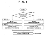
- Fig. 5 is a flowchart illustrating the flow of processing for generating print data according to this embodiment.
- the processing illustrated here is executed by starting up the printer driver of the ink-jet printer installed in the above-mentioned host computer and having the user perform an input operation.
- the ink-jet printer of this embodiment is provided with a plurality of printing modes that include the following two modes: a high-speed mode (mode 1), in which high-speed processing is performed but image quality declines, and a high-quality mode (mode 2), in which high-quality printing is performed but printing speed is low.
- mode 1 high-speed processing is performed but image quality declines
- mode 2 high-quality printing is performed but printing speed is low.
- the user is capable of selecting the printing mode in conformity with the purpose of printing and the degree of image quality desired.
- the ink-jet printer performs printing by scanning a prescribed printing area (an area corresponding to one raster that extends in the main-scan direction of the printhead) a plurality of times, thereby carrying out multiple-pass printing.
- mode 1 "4-pass printing” is executed, while “16-pass printing” is executed in mode 2.
- mode 1 is described in regard to an example in which the high-speed mode (mode 1) is made 4-pass printing and the high-quality mode (mode 2) is made 16-pass printing.
- mode 2 the specific number of passes is not limited to these values.
- the mode in which printing is performed with a comparatively small number of passes is defined as the high-speed mode (mode 1)
- the mode in which printing is performed with a comparatively large number of passes is defined as the high-quality mode (mode 2).
- the printing mode that has been selected at step S1 is determined at steps S2 and S3.
- a color conversion is applied at steps S4 and S5 through the flow of processing shown in Fig. 4.
- Parameters used in the color conversion processing have been set to unique values specific to each of the modes. That is, in this embodiment, the parameters of color conversion processing differ depending upon the printing mode that has been selected. Control then proceeds to step S6, at which quantization processing of the kind described in connection with Fig. 4 is executed and print data is generated.
- Figs. 6A and 6B are diagrams illustrating changes in numbers of large and small dots used according to this embodiment, in which gradation shifts from white to black. Each diagram corresponds to a three-dimensional LUT that provides the parameters of processing executed at the color-conversion processing step 201 in Fig. 4. Curves 601 and 603 indicated by the dashed lines represent change in the output signal with regard to small dots, and curves 602 and 604 indicated by the solid lines represent change in the output signal with regard to large dots.
- Fig. 6A corresponds to a conversion table of mode 1 (the high-speed mode)
- Fig. 6B corresponds to a conversion table of mode 2 (the high-quality mode).
- an area in which the color is near white (a low-density are having a density lower than a predetermined density) is expressed using only small dots to make the impression of granularity as small as possible.
- Black which is maximum density, is expressed using only large dots in mode 1; it is expressed using large and small dots conjointly in mode 2.
- the number of small dots (the output value) prevailing when printing a high density area is smaller in the high-speed mode (mode 1) in comparison with the high-quality mode (mode 2).
- mode 1 it is so arranged that small dots are not used in the printing of an area of maximum density in which the maximum number of large dots is used, thereby preventing the occurrence of stripes or unevenness ascribable to a disturbance in impact position of the small dots caused by the effects of air currents.
- mode 2 on the other hand, the number of passes is large and therefore, taking into account the fact that the number of dots discharged in a single pass diminishes as does the influence upon the impact position of small dots, small dots are used only when printing an area of large density in which the maximum number of large dots is used. In mode 2, therefore, it is possible to make the density of a maximum-density area even higher, as a result of which a high-quality image of improved tonality is obtained.
- the number of small dots used is made comparatively small, or absolutely no small dots are used, in case of high-speed printing, thereby suppressing the occurrence of stripes and unevenness in high-density areas and making it possible to print at high speed without sacrificing image quality to the maximum degree.
- the number of passes is increased, thereby making the number of small dots used comparatively large while suppressing the occurrence of stripes and unevenness. This makes it possible to print a high-quality image of improved tonality.
- the first embodiment relates to a printing system for forming a color image using three types of inks, namely inks of the colors cyan, magenta and yellow.
- a second embodiment concerns a printing system for forming a color image of higher image quality using black ink in addition to the cyan, magenta and yellow inks.
- this embodiment also is a printing system comprising an ink-jet printer and a host computer.
- the structures of the ink-jet printer and host computer also are approximately the same with the exception of the structure of the printhead unit in the ink-jet printer and the parameters used when the color conversion processing is executed. Aspects similar to those of the first embodiment need not be described. The description that follows will center on the characterizing features of this embodiment.
- Fig. 7 is a diagram in which the ink-jet printhead unit 5 according to this embodiment is seen from a printed surface.
- the ink-jet printhead unit 5 has a printhead 11K for black (K) ink, which is provided on its left in Fig. 7, in addition to the two printheads that discharge large and small dots for each of the colors C, M, Y.
- the printhead 11K is connected to ink tank 5a for black (K) ink.
- the printhead 11K is provided with 128 nozzles at a pitch of 600 dpi and discharges ink droplets (large dots), which have a volume of approximately 5 ng, from each of the nozzles in accordance with print data.
- rows of large and small nozzles for discharging respective ones of large and small dots are not provided for the black (K); only a row of large nozzles for discharging large dots is provided for black (K).
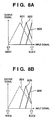
- Figs. 8A and 8B are diagrams illustrating, in a manner similar to that of Figs. 6A and 6B, how large dots, small dots and black ink droplets (black dots) are used in this embodiment.
- Each diagram corresponds to a three-dimensional LUT that provides the parameters of processing executed at the color-conversion processing step 201 in Fig. 4.
- Curves 801 and 804 indicated by the dashed lines represent change in the output signal with regard to small dots
- curves 802 and 805 indicated by the solid lines represent change in the output signal with regard to large dots
- curves 803 and 806 indicated by the bold lines represent change in the output signal with regard to black dots.
- Fig. 8A corresponds to a conversion table of mode 1 (the high-speed mode)
- Fig. 8B corresponds to a conversion table of mode 2 (the high-quality mode).
- the number of small dots used when printing an area of high density in mode 1 differs from that in mode 2, as illustrated, in a manner similar to that of the first embodiment.
- the area is expressed using large dots of the colors CMYK in mode 1 and using large dots of the colors CMYK and small dots of the colors CMY conjointly in mode 2.
- the number of small dots used is made comparatively small, or absolutely no small dots are used, in case of high-speed printing, thereby suppressing the occurrence of stripes and unevenness in high-density areas and making it possible to print at high speed without sacrificing image quality to the maximum degree.
- the number of small dots used is made comparatively large, thereby making it possible to print a high-quality image of improved tonality and devoid of stripes and unevenness.
- black of maximum density is expressed by a mixture of black ink and color ink.
- this may be expressed by black ink only.
- the first and second embodiments described above are such that when the color black is expressed, the numbers of small dots used to print an area of high density are made to differ in dependence upon the printing mode.
- a third embodiment is so adapted that when another chromatic color is expressed, the numbers of small dots used to print an area of high density are made to differ in dependence upon the printing mode.
- this embodiment also is a printing system comprising an ink-jet printer and a host computer.
- the structures of the ink-jet printer and host computer also are approximately the same with the exception of the parameters used when the color conversion processing is executed. Aspects similar to those of the first and second embodiments need not be described. The description that follows will center on the characterizing features of this embodiment.
- the invention is similarly applicable to other chromatic colors. Further, the invention may be applied to a plurality of colors, not just a single color. In such case it is preferred that ink colors such as CMY (and K) or colors such as red, green and blue be supported as the colors applied.
- ink colors such as CMY (and K) or colors such as red, green and blue be supported as the colors applied.
- Figs. 9A and 9B are diagrams illustrating, in a manner similar to that of Figs. 6A and 6B, how large dots and small dots are used in this embodiment.
- Each diagram corresponds to a three-dimensional LUT that provides the parameters of processing executed at the color-conversion processing step 201 in Fig. 4.
- Curves 901 and 903 indicated by the dashed lines represent change in the output signal with regard to small dots
- curves 902 and 904 indicated by the solid lines represent change in the output signal with regard to large dots.
- Fig. 9A corresponds to a conversion table of mode 1 (the high-speed mode)
- Fig. 9B corresponds to a conversion table of mode 2 (the high-quality mode).
- the number of small dots used when printing an area of high density in mode 1 differs from that in mode 2, as illustrated, in a manner similar to that of the first embodiment.
- the area is expressed using only large dots of the color cyan in mode 1 and using large dots and small dots of the color cyan conjointly in mode 2.
- the number of small dots used when printing an area of high cyan density is changed depending upon the printing mode.
- the ink used there are instances where saturation declines even though the density is high.
- the X axis in Figs. 9A and 9B would correspond to saturation.
- the parameters of processing executed in the color conversion are given in the form of three-dimensional LUTs in accordance with the printing mode selected.
- parameters may be given in another form as a matter of course. For example, in a case where only parameters corresponding to one printing mode are stored in advance and another printing mode is selected, a method in which parameters are decided upon performing a predetermined computation is conceivable.
- values of an output signal plotted against an input signal may be found by a method other than one using a three-dimensional LUT, e.g., by performing a predetermined computation.
- the present invention may be applied to a printing system comprising a plurality of devices, as in the embodiments set forth above, or to a stand-alone printing apparatus.
- the present invention is applied to a printing apparatus that has a slot for a PC card or memory card, etc., or that is capable of being connected to an image input device such as a digital camera, the printing apparatus being so adapted that it is capable of printing image data stored on a card that has been inserted into the slot or image data that has been output from the image input device independently without the intermediary of a host device such as a computer.
- the color conversion processing and quantization processing described in the foregoing embodiments would be executed within the printing apparatus.
- a printing apparatus may take on the form of a copier combined with a reader or the like, or a facsimile machine having a transceive function.
- the high-speed mode (mode 1) can be made printing by a single pass
- the high-quality mode (mode 2) can be made multiple-pass printing. More specifically, according to the present invention, it will suffice to provide at least a high-speed mode (mode 1) in which "M" (a positive integer) is a first value and a high-quality mode (mode 2) in which "M” is a value larger than the first value as printing modes for printing a prescribed printing area (an area capable of being printed in the main-scan direction by a single nozzle, namely an area corresponding to one raster) by M-number of scans.
- a prescribed printing area an area capable of being printed in the main-scan direction by a single nozzle, namely an area corresponding to one raster
- the scanning speed of the head may be changed rather than the number of passes. More specifically, the scanning speed of the head would be made comparatively high in the high-speed mode (mode 1) and comparatively low in the high-quality mode (mode 2).
- the scanning speed of the head would be made comparatively high in the high-speed mode (mode 1) and comparatively low in the high-quality mode (mode 2).
- the high-speed mode is defined as a first mode in which the printing of a prescribed area on a print medium is completed in a predetermined time
- the high-quality mode can be defined as a second mode in which the printing of the prescribed area is completed in a time longer than the predetermined time.
- a printer which comprises means (e.g., an electrothermal transducer, laser beam generator, and the like) for generating heat energy as energy utilized upon execution of ink discharge, and causes a change in state of an ink by the heat energy.
- means e.g., an electrothermal transducer, laser beam generator, and the like
- the object of the invention is attained also by supplying a software program (a program corresponding to the flowcharts shown in Figs. 4 and 5 of the foregoing embodiments), which implements the functions of the foregoing embodiments, directly or remotely to a system or apparatus, reading the supplied program codes with a computer of the system or apparatus, and then executing the program codes.
- a software program a program corresponding to the flowcharts shown in Figs. 4 and 5 of the foregoing embodiments
- the mode of implementation need not rely upon a program.
- the program codes per se installed in the computer also implement the present invention.
- the claims of the present invention also cover a computer program that is for the purpose of implementing the functions of the present invention.
- the form of the program e.g., object code, a program executed by an interpreter or script data supplied to an operating system, etc., does not matter.
- Examples of storage media that can be used for supplying the program are a floppy disk, hard disk, optical disk, magneto-optical disk, CD-ROM, CD-R, CD-RW, magnetic tape, non-volatile type memory card, ROM, DVD (DVD-ROM, DVD-R), etc.
- a client computer can be connected to a website on the Internet using a browser possessed by the client computer, and the computer program per se of the present invention or an automatically installable compressed file of the program can be downloaded to a recording medium such as a hard disk.
- the program of the present invention can be supplied by dividing the program code constituting the program into a plurality of files and downloading the files from different websites.
- a WWW World Wide Web
- a storage medium such as a CD-ROM
- distribute the storage medium to users, allow users who meet certain requirements to download decryption key information from a website via the Internet, and allow these users to run the encrypted program by using the key information, whereby the program is installed in the user computer.
- an operating system or the like running on the computer may perform all or a part of the actual processing so that the functions of the foregoing embodiment can be implemented by this processing.
- a CPU or the like mounted on the function expansion board or function expansion unit performs all or a part of the actual processing so that the functions of the foregoing embodiments can be implemented by this processing.
Claims (7)
- Dispositif d'impression à jet d'encre destiné à effectuer une impression en balayant une tête (5) d'impression à jet d'encre sur un support (1) d'impression, la tête (5) d'impression ayant des orifices pour décharger des gouttelettes d'encre d'un premier volume ainsi que des orifices pour décharger des gouttelettes d'encre d'un deuxième volume plus petit que le premier volume, et ledit dispositif étant capable d'imprimer soit dans un premier mode dans lequel on exécute une impression dans une zone prescrite du support d'impression en balayant la tête (5) d'impression à jet d'encre un nombre prédéterminé de fois, soit dans un deuxième mode dans lequel on exécute une impression dans la zone prescrite en balayant la tête (5) d'impression à jet d'encre un nombre de fois plus grand que le nombre de fois prédéterminé, ledit dispositif étant caractérisé par :un moyen (1701) de discrimination de mode pour discriminer celui du premier et du deuxième mode qui a été établi ;un moyen (1701) de production pour produire des données d'impression conformément au mode discriminé par ledit moyen de discrimination de mode ; etun moyen (1704 ; 1705) de commande d'impression pour exécuter une impression en déchargeant une encre vers le support (1) d'impression à partir de la tête (5) d'impression à jet d'encre sur la base des données d'impression ;dans lequel chacun des premier mode et deuxième mode est capable d'exécuter une impression en utilisant la gouttelette d'encre du premier volume et la gouttelette d'encre du deuxième volume, et
dans lequel un nombre de gouttelette(s) d'encre du deuxième volume utilisé dans l'impression d'une zone exprimant une densité maximum par rapport à une couleur prescrite dans le premier mode est inférieur à un nombre de gouttelette(s) d'encre du deuxième volume utilisé dans l'impression de la zone exprimant une densité maximum dans le deuxième mode. - Dispositif selon la revendication 1, caractérisé en ce que, dans le premier mode, la zone exprimant une densité maximum par rapport à la couleur prescrite est imprimée en utilisant des gouttelettes d'encre du premier volume sans utiliser de gouttelettes d'encre du deuxième volume.
- Procédé pour produire des données d'impression devant être utilisées par un dispositif d'impression à jet d'encre qui effectue une impression en balayant une tête (5) d'impression à jet d'encre sur un support (1) d'impression, ladite tête (5) d'impression à jet d'encre ayant des orifices pour décharger des gouttelettes d'encre d'un premier volume ainsi que des orifices pour décharger des gouttelettes d'encre d'un deuxième volume plus petit que le premier volume, ledit procédé étant caractérisé par:une étape (S1) de sélection sélectionnant un mode, qui doit être utilisé lors de l'impression, à partir d'une pluralité de modes incluant un premier mode dans lequel on éxécute une impression dans une zone prescrite sur le support (1) d'impression en balayant la tête (5) d'impression à jet d'encre un nombre prédéterminé de fois et un deuxième mode dans lequel on exécute une impression dans la zone prescrite en balayant la tête (5) d'impression à jet d'encre un nombre de fois plus grand que le nombre de fois prédéterminé, chacun des premier mode et deuxième mode étant capable d'exécuter l'impression en utilisant la gouttelette d'encre du premier volume et la gouttelette d'encre du deuxième volume ; etune étape (S6) de production de données produisant des données d'impression conformément au mode sélectionné ;dans lequel un nombre de gouttelette(s) d'encre du deuxième volume utilisé dans l'impression d'une zone exprimant une densité maximum par rapport à une couleur prescrite dans le premier mode est inférieur à un nombre de gouttelette(s) d'encre du deuxième volume utilisé dans l'impression de la zone exprimant une densité maximum dans le deuxième mode.
- Procédé selon la revendication 3, caractérisé en ce que, dans le premier mode, la zone exprimant une densité maximum par rapport à la couleur prescrite est imprimée en utilisant des gouttelettes d'encre du premier volume sans utiliser de gouttelettes d'encre du deuxième volume.
- Procédé d'impression à jet d'encre destiné à effectuer une impression en balayant une tête (5) d'impression à jet d'encre sur un support (1) d'impression, ledit procédé comportant :une étape (S6) de production des données d'impression par ledit procédé selon la revendication 3 ou 4; etune étape d'exécution d'impression en déchargeant une encre vers le support d'impression à partir de la tête d'impression à jet d'encre sur la base des données d'impression produites dans ladite étape (S6) de production.
- Programme destiné à produire des données d'impression devant être transmises à un dispositif d'impression à jet d'encre qui effectue une impression en balayant une tête (5) d'impression à jet d'encre sur un support (1) d'impression, ledit programme étant caractérisé en ce que l'on provoque l'exécution par un ordinateur :d'une étape de production (S6) des données d'impression par ledit procédé selon la revendication 3 ou 4.
- Support de stockage pouvant être lu par un ordinateur stockant le programme selon la revendication 6.
Applications Claiming Priority (2)
| Application Number | Priority Date | Filing Date | Title |
|---|---|---|---|
| JP2002263222 | 2002-09-09 | ||
| JP2002263222A JP4012023B2 (ja) | 2002-09-09 | 2002-09-09 | インクジェット記録方法、記録システム、インクジェット記録装置、制御方法およびプログラム |
Publications (3)
| Publication Number | Publication Date |
|---|---|
| EP1396345A2 EP1396345A2 (fr) | 2004-03-10 |
| EP1396345A3 EP1396345A3 (fr) | 2004-05-19 |
| EP1396345B1 true EP1396345B1 (fr) | 2006-12-13 |
Family
ID=31712360
Family Applications (1)
| Application Number | Title | Priority Date | Filing Date |
|---|---|---|---|
| EP03020286A Expired - Lifetime EP1396345B1 (fr) | 2002-09-09 | 2003-09-08 | Méthode, système et appareil d'impression à jet d'encre, méthode et programme de génération de données d'impression, et pilote d'imprimante |
Country Status (5)
| Country | Link |
|---|---|
| US (2) | US7097267B2 (fr) |
| EP (1) | EP1396345B1 (fr) |
| JP (1) | JP4012023B2 (fr) |
| CN (1) | CN1310758C (fr) |
| DE (1) | DE60310324T2 (fr) |
Families Citing this family (22)
| Publication number | Priority date | Publication date | Assignee | Title |
|---|---|---|---|---|
| JP4564732B2 (ja) * | 2002-10-02 | 2010-10-20 | キヤノン株式会社 | 印刷制御装置、印刷制御方法、プリントシステム、プログラム |
| JP4497807B2 (ja) * | 2002-11-26 | 2010-07-07 | キヤノン株式会社 | 記録装置および該装置の制御方法 |
| JP2005177989A (ja) * | 2003-12-15 | 2005-07-07 | Canon Inc | インクジェット記録装置及びそのインクジェット記録方法 |
| WO2005120833A1 (fr) * | 2004-06-09 | 2005-12-22 | Canon Kabushiki Kaisha | Méthode d’enregistrement de jet d’encre |
| JP4652894B2 (ja) * | 2004-06-09 | 2011-03-16 | キヤノン株式会社 | インクジェット記録方法、インクジェット記録装置、およびプログラム |
| KR100823257B1 (ko) * | 2005-07-28 | 2008-04-17 | 삼성전자주식회사 | 잉크젯 화상형성장치 및 잉크젯 화상형성장치의 인쇄 방법 |
| US7517039B2 (en) * | 2005-09-19 | 2009-04-14 | Marvell International Technology Ltd. | Enabling increased print speed by eliminating nozzle firing sequencing |
| JP2009154365A (ja) * | 2007-12-26 | 2009-07-16 | Ricoh Co Ltd | 画像処理装置、画像処理方法、画像処理プログラム及び記録媒体 |
| JP5171321B2 (ja) * | 2008-03-07 | 2013-03-27 | キヤノン株式会社 | 画像処理装置および画像処理方法 |
| JP2010247519A (ja) | 2009-03-24 | 2010-11-04 | Seiko Epson Corp | 印刷装置 |
| JP5244667B2 (ja) * | 2009-03-24 | 2013-07-24 | 大日本スクリーン製造株式会社 | インクジェットプリンタおよび印刷方法 |
| US8711425B2 (en) * | 2010-05-28 | 2014-04-29 | Hewlett-Packard Development Company, L.P. | Selecting one of a plurality of print modes based on pixel coverage of a document |
| JP5720316B2 (ja) * | 2011-03-09 | 2015-05-20 | セイコーエプソン株式会社 | プリンター |
| JP6048244B2 (ja) * | 2013-03-19 | 2016-12-21 | セイコーエプソン株式会社 | 印刷装置および印刷方法 |
| JP2016007789A (ja) * | 2014-06-25 | 2016-01-18 | セイコーエプソン株式会社 | インクジェットプリンタ、およびその制御方法 |
| US9168737B1 (en) * | 2015-01-29 | 2015-10-27 | Funai Electric Co., Ltd. | System and method for ejecting adjustable amounts of ink |
| EP3455076B1 (fr) | 2016-10-25 | 2021-04-21 | Hewlett-Packard Development Company, L.P. | Maintien d'un paramètre de qualité d'impression dans une imprimante |
| JP7089219B2 (ja) * | 2018-05-10 | 2022-06-22 | ブラザー工業株式会社 | 制御プログラム、情報処理装置、およびシステム |
| JP2020026061A (ja) * | 2018-08-10 | 2020-02-20 | セイコーエプソン株式会社 | 記録装置、記録方法、および記録制御装置 |
| JP7292914B2 (ja) | 2019-03-27 | 2023-06-19 | キヤノン株式会社 | インクジェット記録装置およびインクジェット記録方法 |
| WO2020246260A1 (fr) | 2019-06-04 | 2020-12-10 | キヤノン株式会社 | Dispositif d'enregistrement à jet d'encre et procédé d'enregistrement |
| JP2021037701A (ja) | 2019-09-03 | 2021-03-11 | キヤノン株式会社 | インクジェット記録装置 |
Family Cites Families (17)
| Publication number | Priority date | Publication date | Assignee | Title |
|---|---|---|---|---|
| JPS6046520A (ja) | 1983-08-25 | 1985-03-13 | Nippon Kogaku Kk <Nikon> | 顕微鏡対物レンズ |
| US5198833A (en) * | 1987-11-04 | 1993-03-30 | Sharp Kabushiki Kaisha | Variable density ink-jet dot printer |
| JP3058493B2 (ja) | 1991-10-28 | 2000-07-04 | キヤノン株式会社 | インクジェット記録方法,インクジェット記録ヘッドおよびインクジェット記録装置 |
| US5642142A (en) * | 1992-11-30 | 1997-06-24 | Hewlett-Packard Company | Variable halftone operation inkjet printheads |
| EP0649746A1 (fr) | 1993-10-26 | 1995-04-26 | Hewlett-Packard Company | Têtes d'impression à jet d'encre pour l'opération à demi-teinte variable |
| EP1154372B1 (fr) * | 1994-06-17 | 2005-09-21 | Canon Kabushiki Kaisha | Méthode d'enregistrement à jet d'encre et appareil ayant la capacité de transformation de résolution |
| DE69534683T2 (de) * | 1994-12-29 | 2006-07-06 | Canon K.K. | Tintenstrahlkopf mit verschiedenen Heizelementen pro Düse und Tintenstrahldrucker unter Verwendung desselben |
| JP3320289B2 (ja) * | 1995-02-13 | 2002-09-03 | キヤノン株式会社 | インクジェットヘッド、インクジェットカートリッジおよびプリント装置ならびにインクジェットプリント方法 |
| US5745131A (en) * | 1995-08-03 | 1998-04-28 | Xerox Corporation | Gray scale ink jet printer |
| US6283571B1 (en) | 1998-07-03 | 2001-09-04 | Seiko Epson Corporation | Printer and recording medium |
| JP3414325B2 (ja) | 1998-07-03 | 2003-06-09 | セイコーエプソン株式会社 | 印刷装置および記録媒体 |
| JP2000071439A (ja) | 1998-08-31 | 2000-03-07 | Seiko Epson Corp | 画像処理装置および方法並びに記録媒体 |
| JP3687381B2 (ja) | 1998-12-21 | 2005-08-24 | セイコーエプソン株式会社 | 印刷装置、印刷方法および記録媒体 |
| US6364452B1 (en) * | 1999-04-14 | 2002-04-02 | Canon Kabushiki Kaisha | Color printing using multiple inks |
| JP2001150654A (ja) | 1999-11-26 | 2001-06-05 | Seiko Epson Corp | インク量の異なるインク滴を用いる印刷装置、印刷方法 |
| US6547354B1 (en) | 2000-07-28 | 2003-04-15 | Hewlett-Packard Company | Printing system that utilizes print masks with resolutions that are non-integral multiples of each other |
| US6409318B1 (en) * | 2000-11-30 | 2002-06-25 | Hewlett-Packard Company | Firing chamber configuration in fluid ejection devices |
-
2002
- 2002-09-09 JP JP2002263222A patent/JP4012023B2/ja not_active Expired - Fee Related
-
2003
- 2003-09-03 US US10/653,207 patent/US7097267B2/en not_active Expired - Lifetime
- 2003-09-08 DE DE60310324T patent/DE60310324T2/de not_active Expired - Lifetime
- 2003-09-08 CN CNB031568238A patent/CN1310758C/zh not_active Expired - Fee Related
- 2003-09-08 EP EP03020286A patent/EP1396345B1/fr not_active Expired - Lifetime
-
2006
- 2006-05-01 US US11/414,186 patent/US7556343B2/en not_active Expired - Fee Related
Also Published As
| Publication number | Publication date |
|---|---|
| CN1310758C (zh) | 2007-04-18 |
| EP1396345A3 (fr) | 2004-05-19 |
| US7097267B2 (en) | 2006-08-29 |
| DE60310324D1 (de) | 2007-01-25 |
| US20040046817A1 (en) | 2004-03-11 |
| US20060192800A1 (en) | 2006-08-31 |
| JP4012023B2 (ja) | 2007-11-21 |
| EP1396345A2 (fr) | 2004-03-10 |
| US7556343B2 (en) | 2009-07-07 |
| JP2004098464A (ja) | 2004-04-02 |
| DE60310324T2 (de) | 2007-06-21 |
| CN1500637A (zh) | 2004-06-02 |
Similar Documents
| Publication | Publication Date | Title |
|---|---|---|
| US7556343B2 (en) | Ink-jet printing method, printing system, ink-jet printing apparatus, print data generating method, program and printer driver | |
| US6788434B1 (en) | Image data processing method and image data transfer method | |
| JP4078811B2 (ja) | 画素ブロック単位で濃淡インクによる階調再現を行う印刷 | |
| US7641309B2 (en) | Data processing apparatus, data processing method, ink jet printing apparatus, and ink jet printing method | |
| US7350893B2 (en) | Inkjet printing method | |
| JP4560193B2 (ja) | データ処理方法及びデータ処理装置 | |
| US20080158281A1 (en) | Image forming apparatus and control method thereof | |
| US20090147283A1 (en) | Ejecion control of quality-enhancing ink | |
| US7564591B1 (en) | Image processing apparatus and image processing method | |
| JP4250541B2 (ja) | インクジェット記録装置およびインクジェット記録方法ならびに記録システム | |
| JP4827674B2 (ja) | 記録装置及び記録方法 | |
| JP4590211B2 (ja) | 画像処理装置、画像処理方法、及びプログラム | |
| JP3687381B2 (ja) | 印刷装置、印刷方法および記録媒体 | |
| US6749280B2 (en) | Recording apparatus, recording method therefor and program therefor | |
| JP2012153119A (ja) | インクジェット記録装置及びインクジェット記録方法 | |
| JP2005169736A (ja) | インクジェット記録装置及びインクジェット記録方法 | |
| JP3783636B2 (ja) | 長尺印刷を行う印刷 | |
| JP4280391B2 (ja) | 画像記録装置、ドットパターン決定装置、ドットパターン決定方法およびコンピュータ可読記憶媒体 | |
| JP2006224616A (ja) | 記録方法および記録システム | |
| US20050035987A1 (en) | Ejection control of quality-enhancing ink | |
| JP4032676B2 (ja) | 画像記録方法及びそれを適用した画像記録装置、並びにその画像記録装置に適用される画像記録処理用プログラム | |
| JP2004209765A (ja) | 記録装置及び記録方法 | |
| JP2005001353A (ja) | インクジェット記録方法、記録システム、インクジェット記録装置、記録データ生成方法、プログラム及びプリンタドライバ | |
| JP2023096573A (ja) | 記録装置および記録方法 | |
| JP4193433B2 (ja) | 複数の画像の連続印刷 |
Legal Events
| Date | Code | Title | Description |
|---|---|---|---|
| PUAI | Public reference made under article 153(3) epc to a published international application that has entered the european phase |
Free format text: ORIGINAL CODE: 0009012 |
|
| AK | Designated contracting states |
Kind code of ref document: A2 Designated state(s): AT BE BG CH CY CZ DE DK EE ES FI FR GB GR HU IE IT LI LU MC NL PT RO SE SI SK TR |
|
| AX | Request for extension of the european patent |
Extension state: AL LT LV MK |
|
| PUAL | Search report despatched |
Free format text: ORIGINAL CODE: 0009013 |
|
| AK | Designated contracting states |
Kind code of ref document: A3 Designated state(s): AT BE BG CH CY CZ DE DK EE ES FI FR GB GR HU IE IT LI LU MC NL PT RO SE SI SK TR |
|
| AX | Request for extension of the european patent |
Extension state: AL LT LV MK |
|
| RIC1 | Information provided on ipc code assigned before grant |
Ipc: 7B 41J 2/21 A Ipc: 7B 41J 2/505 B |
|
| 17P | Request for examination filed |
Effective date: 20041001 |
|
| AKX | Designation fees paid |
Designated state(s): DE FR GB IT |
|
| 17Q | First examination report despatched |
Effective date: 20050221 |
|
| GRAP | Despatch of communication of intention to grant a patent |
Free format text: ORIGINAL CODE: EPIDOSNIGR1 |
|
| GRAS | Grant fee paid |
Free format text: ORIGINAL CODE: EPIDOSNIGR3 |
|
| GRAA | (expected) grant |
Free format text: ORIGINAL CODE: 0009210 |
|
| AK | Designated contracting states |
Kind code of ref document: B1 Designated state(s): DE FR GB IT |
|
| REG | Reference to a national code |
Ref country code: GB Ref legal event code: FG4D |
|
| REF | Corresponds to: |
Ref document number: 60310324 Country of ref document: DE Date of ref document: 20070125 Kind code of ref document: P |
|
| ET | Fr: translation filed | ||
| PLBE | No opposition filed within time limit |
Free format text: ORIGINAL CODE: 0009261 |
|
| STAA | Information on the status of an ep patent application or granted ep patent |
Free format text: STATUS: NO OPPOSITION FILED WITHIN TIME LIMIT |
|
| 26N | No opposition filed |
Effective date: 20070914 |
|
| PGFP | Annual fee paid to national office [announced via postgrant information from national office to epo] |
Ref country code: FR Payment date: 20080822 Year of fee payment: 6 Ref country code: IT Payment date: 20080822 Year of fee payment: 6 |
|
| REG | Reference to a national code |
Ref country code: FR Ref legal event code: ST Effective date: 20100531 |
|
| PG25 | Lapsed in a contracting state [announced via postgrant information from national office to epo] |
Ref country code: FR Free format text: LAPSE BECAUSE OF NON-PAYMENT OF DUE FEES Effective date: 20090930 |
|
| PG25 | Lapsed in a contracting state [announced via postgrant information from national office to epo] |
Ref country code: IT Free format text: LAPSE BECAUSE OF NON-PAYMENT OF DUE FEES Effective date: 20090908 |
|
| PGFP | Annual fee paid to national office [announced via postgrant information from national office to epo] |
Ref country code: GB Payment date: 20180928 Year of fee payment: 16 |
|
| GBPC | Gb: european patent ceased through non-payment of renewal fee |
Effective date: 20190908 |
|
| PG25 | Lapsed in a contracting state [announced via postgrant information from national office to epo] |
Ref country code: GB Free format text: LAPSE BECAUSE OF NON-PAYMENT OF DUE FEES Effective date: 20190908 |
|
| PGFP | Annual fee paid to national office [announced via postgrant information from national office to epo] |
Ref country code: DE Payment date: 20201127 Year of fee payment: 18 |
|
| REG | Reference to a national code |
Ref country code: DE Ref legal event code: R119 Ref document number: 60310324 Country of ref document: DE |
|
| PG25 | Lapsed in a contracting state [announced via postgrant information from national office to epo] |
Ref country code: DE Free format text: LAPSE BECAUSE OF NON-PAYMENT OF DUE FEES Effective date: 20220401 |