EP1391874B1 - Musical sound reproducer and mobile terminal - Google Patents
Musical sound reproducer and mobile terminal Download PDFInfo
- Publication number
- EP1391874B1 EP1391874B1 EP02730687A EP02730687A EP1391874B1 EP 1391874 B1 EP1391874 B1 EP 1391874B1 EP 02730687 A EP02730687 A EP 02730687A EP 02730687 A EP02730687 A EP 02730687A EP 1391874 B1 EP1391874 B1 EP 1391874B1
- Authority
- EP
- European Patent Office
- Prior art keywords
- tone
- tone color
- memory
- tone generator
- musical
- Prior art date
- Legal status (The legal status is an assumption and is not a legal conclusion. Google has not performed a legal analysis and makes no representation as to the accuracy of the status listed.)
- Expired - Lifetime
Links
- 230000015654 memory Effects 0.000 claims abstract description 130
- 238000000034 method Methods 0.000 claims description 50
- 230000006870 function Effects 0.000 claims description 7
- 238000010276 construction Methods 0.000 description 11
- 238000010586 diagram Methods 0.000 description 10
- 238000004891 communication Methods 0.000 description 4
- 230000000873 masking effect Effects 0.000 description 4
- 239000012634 fragment Substances 0.000 description 3
- 230000006835 compression Effects 0.000 description 2
- 238000007906 compression Methods 0.000 description 2
- 230000003044 adaptive effect Effects 0.000 description 1
- 230000005540 biological transmission Effects 0.000 description 1
- 230000015572 biosynthetic process Effects 0.000 description 1
- 210000001072 colon Anatomy 0.000 description 1
- 239000003086 colorant Substances 0.000 description 1
- 230000000694 effects Effects 0.000 description 1
- 238000005070 sampling Methods 0.000 description 1
- 238000003786 synthesis reaction Methods 0.000 description 1
Images


Classifications
-
- H—ELECTRICITY
- H04—ELECTRIC COMMUNICATION TECHNIQUE
- H04M—TELEPHONIC COMMUNICATION
- H04M19/00—Current supply arrangements for telephone systems
- H04M19/02—Current supply arrangements for telephone systems providing ringing current or supervisory tones, e.g. dialling tone or busy tone
- H04M19/04—Current supply arrangements for telephone systems providing ringing current or supervisory tones, e.g. dialling tone or busy tone the ringing-current being generated at the substations
- H04M19/041—Encoding the ringing signal, i.e. providing distinctive or selective ringing capability
-
- G—PHYSICS
- G10—MUSICAL INSTRUMENTS; ACOUSTICS
- G10H—ELECTROPHONIC MUSICAL INSTRUMENTS; INSTRUMENTS IN WHICH THE TONES ARE GENERATED BY ELECTROMECHANICAL MEANS OR ELECTRONIC GENERATORS, OR IN WHICH THE TONES ARE SYNTHESISED FROM A DATA STORE
- G10H1/00—Details of electrophonic musical instruments
- G10H1/18—Selecting circuits
- G10H1/24—Selecting circuits for selecting plural preset register stops
-
- G—PHYSICS
- G10—MUSICAL INSTRUMENTS; ACOUSTICS
- G10H—ELECTROPHONIC MUSICAL INSTRUMENTS; INSTRUMENTS IN WHICH THE TONES ARE GENERATED BY ELECTROMECHANICAL MEANS OR ELECTRONIC GENERATORS, OR IN WHICH THE TONES ARE SYNTHESISED FROM A DATA STORE
- G10H7/00—Instruments in which the tones are synthesised from a data store, e.g. computer organs
- G10H7/02—Instruments in which the tones are synthesised from a data store, e.g. computer organs in which amplitudes at successive sample points of a tone waveform are stored in one or more memories
-
- G—PHYSICS
- G10—MUSICAL INSTRUMENTS; ACOUSTICS
- G10H—ELECTROPHONIC MUSICAL INSTRUMENTS; INSTRUMENTS IN WHICH THE TONES ARE GENERATED BY ELECTROMECHANICAL MEANS OR ELECTRONIC GENERATORS, OR IN WHICH THE TONES ARE SYNTHESISED FROM A DATA STORE
- G10H2230/00—General physical, ergonomic or hardware implementation of electrophonic musical tools or instruments, e.g. shape or architecture
- G10H2230/005—Device type or category
- G10H2230/021—Mobile ringtone, i.e. generation, transmission, conversion or downloading of ringing tones or other sounds for mobile telephony; Special musical data formats or protocols therefor
-
- G—PHYSICS
- G10—MUSICAL INSTRUMENTS; ACOUSTICS
- G10H—ELECTROPHONIC MUSICAL INSTRUMENTS; INSTRUMENTS IN WHICH THE TONES ARE GENERATED BY ELECTROMECHANICAL MEANS OR ELECTRONIC GENERATORS, OR IN WHICH THE TONES ARE SYNTHESISED FROM A DATA STORE
- G10H2230/00—General physical, ergonomic or hardware implementation of electrophonic musical tools or instruments, e.g. shape or architecture
- G10H2230/025—Computing or signal processing architecture features
- G10H2230/031—Use of cache memory for electrophonic musical instrument processes, e.g. for improving processing capabilities or solving interfacing problems
-
- G—PHYSICS
- G10—MUSICAL INSTRUMENTS; ACOUSTICS
- G10H—ELECTROPHONIC MUSICAL INSTRUMENTS; INSTRUMENTS IN WHICH THE TONES ARE GENERATED BY ELECTROMECHANICAL MEANS OR ELECTRONIC GENERATORS, OR IN WHICH THE TONES ARE SYNTHESISED FROM A DATA STORE
- G10H2240/00—Data organisation or data communication aspects, specifically adapted for electrophonic musical tools or instruments
- G10H2240/011—Files or data streams containing coded musical information, e.g. for transmission
- G10H2240/046—File format, i.e. specific or non-standard musical file format used in or adapted for electrophonic musical instruments, e.g. in wavetables
- G10H2240/056—MIDI or other note-oriented file format
-
- G—PHYSICS
- G10—MUSICAL INSTRUMENTS; ACOUSTICS
- G10H—ELECTROPHONIC MUSICAL INSTRUMENTS; INSTRUMENTS IN WHICH THE TONES ARE GENERATED BY ELECTROMECHANICAL MEANS OR ELECTRONIC GENERATORS, OR IN WHICH THE TONES ARE SYNTHESISED FROM A DATA STORE
- G10H2240/00—Data organisation or data communication aspects, specifically adapted for electrophonic musical tools or instruments
- G10H2240/171—Transmission of musical instrument data, control or status information; Transmission, remote access or control of music data for electrophonic musical instruments
- G10H2240/201—Physical layer or hardware aspects of transmission to or from an electrophonic musical instrument, e.g. voltage levels, bit streams, code words or symbols over a physical link connecting network nodes or instruments
- G10H2240/241—Telephone transmission, i.e. using twisted pair telephone lines or any type of telephone network
- G10H2240/251—Mobile telephone transmission, i.e. transmitting, accessing or controlling music data wirelessly via a wireless or mobile telephone receiver, analogue or digital, e.g. DECT, GSM, UMTS
-
- H—ELECTRICITY
- H04—ELECTRIC COMMUNICATION TECHNIQUE
- H04M—TELEPHONIC COMMUNICATION
- H04M19/00—Current supply arrangements for telephone systems
- H04M19/02—Current supply arrangements for telephone systems providing ringing current or supervisory tones, e.g. dialling tone or busy tone
- H04M19/04—Current supply arrangements for telephone systems providing ringing current or supervisory tones, e.g. dialling tone or busy tone the ringing-current being generated at the substations
- H04M19/047—Vibrating means for incoming calls
Definitions
- the present invention relates to a musical tone reproducing apparatus capable of changing tone color, and a portable terminal apparatus having the musical tone reproducing apparatus.
- Conventional musical tone reproducing apparatuses include ones that generate musical tones using hardware. Such a musical tone reproducing apparatus is constructed such that the tone color of reproduced musical tones can be changed.
- a CPU 110 reads sequence data such as MIDI (musical instrument digital interface) data or SMAF (synthetic music mobile application format) data out from a RAM (random access memory) 111, and supplies the sequence data to a tone generator hardware section 115.
- the tone generator hardware section 115 reproduces the sequence data supplied from the RAM 111, and accordingly outputs musical tone signals to a speaker 134.
- the tone generator hardware section 115 is comprised of a tone color parameter storage region 130, and a data processing section 133 that carries out a musical tone reproducing process.
- the tone color parameter storage region 130 is comprised of registers or regions reserved in the RAM 111.
- the CPU 110 when changing the tone color of a musical tone to be reproduced, gives a tone color changing command to the tone color parameter storage region 130, and also reads a tone color parameter for the tone color to be changed to out from the RAM 111, and writes the tone color parameter into the tone color parameter storage region 130.
- the data processing section 133 reads the tone color parameter for the tone color to be changed to out from the tone color parameter storage region 130, and carries out musical tone reproduction with a tone color changed using the tone color parameter. Note that much sequence data and a plurality of tone color parameters (a tone color parameter group) can be stored in the RAM 111.
- the CPU 110 when changing the tone color, the CPU 110 reads the tone color parameter for the tone color to be changed to out from the RAM 111 and transfers the tone color parameter to the tone generator hardware section 115 as described above.
- the data bus width of the tone generator hardware section 115 is approximately 8 bits
- the bit width of the RAM or registers constituting the tone color parameter storage region 130 i.e. the bit width of the stored data, is also limited to being approximately 8 bits.
- one or more tone color parameters for one channel required when the data processing section 133 carries out the tone reproducing process for one channel are comprised of many bits, specifically several tens of bits.
- the tone color parameter storage region 130 is comprised of registers exclusively for this purpose, then reading out from a freely chosen number of registers can be carried out simultaneously, but the tone color parameter storage region 130 becomes a region exclusively for tone color parameters, and hence a problem arises that if the tone color parameter storage region 130 is also used for general-purpose data having a width of 8 bits other than tone color parameters, then the efficiency of usage of the tone color parameter storage region 130 as a memory becomes poor.
- the tone color parameter storage region 130 is comprised of a RAM having a large bit width, then a tone color parameter having a large bit width can be read out at a time, but the tone color parameter storage region 130 becomes a region exclusively for tone color parameters, and hence a problem again arises that if the tone color parameter storage region 130 is also used for general-purpose data having a width of 8 bits other than tone color parameters, then the efficiency of usage of the tone color parameter storage region 130 as a memory becomes poor.
- the use of several cache tone colon parameter memories for each tone generator is known from US-A 5 345 035 .
- a musical tone reproducing apparatus of the present invention provides in a portable terminal apparatus having system storage means as a general-purpose memory for storing various data including a tone color parameter group and system control means for controlling the whole apparatus including the system storage means, and that carries out musical tone reproduction in cooperation with the system storage means and the system control means, the musical tone reproducing apparatus comprising a tone generator memory as a general-purpose memory in which is registered at least a tone color parameter group comprising a freely chosen number of tone color parameters read out from the system storage means, a cache memory into which are inputted tone color parameters from the registered tone color parameter group at a predetermined data width from the tone generator memory and from which are outputted the inputted tone color parameters at a data width larger than the predetermined data width, tone generator means for carrying out musical tone reproduction based on tone color parameters outputted from the cache memory, and tone generator control means for controlling the musical tone reproducing apparatus based on commands from the system control means, wherein, based on a command for tone color parameter registration from the system control means,
- the system control means reads out each of the tone color parameters from the tone generator memory by specifying a leading address of the predetermined addresses given to the tone color parameters.
- the system control means writes into the system storage means and reads out from the system storage means leading addresses of the predetermined addresses given to the tone color parameters stored in the tone generator memory.
- the tone generator memory outputs to the cache memory at a data width smaller than one channel's worth of the tone color parameters.
- the cache memory outputs at least one channel's worth of the tone color parameters to the tone generator means at a time.
- the tone generator means carries out the musical tone reproduction based on sequence data that has been converted into a predetermined format.
- the tone generator memory comprises a first tone generator memory and a second tone generator memory
- the tone generator control means determines whether a leading address contained in a command from the system control means is within the first tone generator memory or within the second tone generator memory, and reads out a tone color parameter corresponding to the leading address within the first tone generator memory or the second tone generator memory.
- the first tone generator memory is a RAM (random access memory)
- the second tone generator memory is a ROM (read only memory).
- the portable terminal apparatus has data receiving means for receiving external data, and data received by the data receiving means is stored in the system storage means.
- a portable terminal apparatus of the present invention has a musical tone reproducing apparatus as described above, wherein the system control means carries out a portable terminal apparatus function process as a main process.
- FIG. 1 is a diagram showing an example of the construction of a portable terminal apparatus according to an embodiment of the present invention.
- a mobile phone 1 which is the portable terminal apparatus, and which generally has a retractable antenna 25, can be connected to a base station 2 by a wireless communication line.
- the antenna 25 is connected to a communication section 13 having functions of modulation and demodulation.
- a CPU (central processing unit) 10 serves as a system controller that controls operations of various sections of the mobile phone 1 by executing telephone function programs, and is provided with a timer (not shown) that shows elapsed time in the operations and generates a timer interrupt at predetermined time intervals. Moreover, the CPU 10 transfers sequence data by a predetermined amount at a time to a tone generator hardware section 15 during musical tone reproduction carried out, for example, upon receipt of an incoming call.
- a RAM (random access memory) 11 has set therein a storage area for sequence data downloaded from a downloading center or the like connected via the base station 2, a work area for the CPU 10, and so on.
- a ROM (read only memory) 12 stores various programs executed by the CPU 10 including various telephone function programs for carrying out transmission and reception and programs for carrying out processes relating to musical tone reproduction and the like, and also various kinds of data such as preset sequence data.
- the communication section 13 demodulates a signal received by the antenna 25, and modulates a signal to be transmitted to the base station 2 and supplies the modulated signal to the antenna 25.
- An incoming speech signal that has been demodulated by the communication section 13 is decoded by a speech processing section (coder/decoder) 14, and a speech signal inputted via a microphone 21 is subjected to compression encoding by the speech processing section 14.
- the speech processing section 14, which subjects the speech to efficient compression encoding/decoding is comprised, for example, of a coder/decoder of CELP (Code Excited LPC) type or ADPCM (Adaptive Differential PCM coding) type.
- the tone generator hardware section 15 is able to sound the incoming speech signal from the speech processing section 14 through an incoming speech speaker 22, and generate and output an incoming call melody and holding music by reproducing the sequence data.
- the incoming call melody is sounded from an incoming call speaker 23, and the holding music is mixed with the incoming speech signal and sounded from the incoming speech speaker 22.
- the format of the sequence data is a MIDI (Musical Instrument Digital Interface) format or a SMAF (Synthetic Music Mobile Application Format) format, which is convenient for data distribution.
- the tone generator hardware section 15 converts sequence data of such a format into control data of a format peculiar to a tone generator core built into the tone generator hardware section 15, and reproduces the converted data.
- the CPU 10 may convert the sequence data into control data of a format peculiar to the tone generator hardware section 15, store the converted data in the RAM 11, and read out the same from the RAM 11 and supply the same to the tone generator hardware section 15 during reproduction.
- the tone generator hardware section 15 has provided therein a general-purpose RAM in which is registered a tone color parameter group of a freely chosen number of tone color parameters, a cache memory having a large output bit width, and the tone generator core.
- the tone color parameter group registered in the general-purpose RAM is, for example, a tone color parameter group according to General MIDI Standard.
- the cache memory stores tone color parameters for a tone color specified for each channel, and the tone generator core can read out a tone color parameter for one channel required for musical tone reproduction for that channel by accessing the cache memory only once or a few times.
- An interface (I/F) 16 is for downloading sequence data and so on from an external apparatus 20 such as a personal computer.
- An input section 17 serves as an input means comprised of dialing buttons "0" to "9” and various other buttons provided in the mobile phone 1.
- a display section 18 is comprised of a display device that displays telephone function menus and other displays according to operations of the buttons such as the dialing buttons.
- a vibrator 19 notifies a user of incoming calls by vibrating the main body of the mobile phone 1 instead of the incoming call melody when there is an incoming call.
- the various function blocks transfer and receive data and so on via a bus 24.
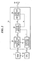
- FIG. 2 an example of the construction of a musical tone reproducing apparatus installed in the portable terminal apparatus shown in FIG. 1 is shown in FIG. 2 .
- the incoming speech speaker 22 and the incoming call speaker 23 are shown as a speaker 34, i.e. the constructions of the incoming speech speaker 22 and the incoming call speaker 23 are omitted.
- data transfer between the CPU 10, the tone generator hardware section 15 and the RAM 11 is carried out via the bus 24, but the bus 24 is not shown in FIG. 2 .
- sequence data, and a tone color parameter group for various tone colors according to the General MIDI Standard or the like are stored in the RAM 11.
- the tone color parameter group according to the General MIDI Standard or the like stored in the RAM 11 are transferred to and registered in a tone generator memory 30 of the tone generator hardware section 15 under the control of the CPU 10.
- the CPU 10 gives a tone color parameter transmitting command a to the RAM 11, and the tone color parameters in the tone color parameter group to be registered are sequentially read out, and the read out tone color parameters b are supplied to the tone generator memory 30.
- the CPU 10 gives a tone color parameter write (register tone color parameters into memory) command c to a controller 31.
- the controller 31 Upon receiving the tone color parameter write command c, the controller 31 generates addresses at which the tone color parameters b are to be written into the tone generator memory 30, and gives a tone color parameter writing command d to the tone generator memory 30.
- the tone color parameters a read out from the RAM 11 are written into a predetermined region of the tone generator memory 30.
- a tone color parameter table in which is written the leading address for each tone color parameter registered in the tone generator memory 30 is stored by the CPU 10 in a work area of the RAM 11.
- the CPU 10 When changing the tone color of a musical tone to be reproduced by the tone generator core 33, the CPU 10 gives a tone color changing command c to the controller 31. Having received the tone color changing command c, the controller 31 gives to the tone generator memory 30 a tone color parameter transmitting command d to transmit the specified tone color parameter to a cache memory 32. As a result, the tone generator memory 30 reads out the specified tone color parameters, and transmits the read out tone color parameter e to the cache memory 32. Moreover, although not shown in FIG.
- the tone generator core 33 converts sequence data supplied from the controller 31 into control data of a format peculiar to the tone generator core 33, and when reproduction timing for each event in the control data is reached, gives a tone color parameter read request h to the cache memory 32.
- the cache memory 32 Upon receiving the tone color parameter read request h, the cache memory 32 reads out a tone color parameter g, and sends the tone color parameter g to the tone generator core 33.
- the output bit width of the cache memory 32 is set at a bit width such that, for example, the tone color parameter g for one channel can be sent at a time, the tone color parameter can be set in the tone generator core 33 instantaneously.
- the tone generator core 33 reproduces a musical tone of a tone color changed using the changed tone color parameters, and accordingly sends reproduction data i to the speaker 34, whereby the musical tone is sounded.
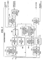
- FIG. 3 is a diagram showing the detailed construction of the tone generator memory 30, the controller 31 and the cache memory 32 in the tone generator hardware section 15 appearing in FIG. 2
- FIG. 4 is a diagram showing an example of the data structure of a tone color parameter group registered in a tone generator RAM 30a appearing in FIG. 3
- FIG. 5 is a diagram showing an example of the data structure of tone color parameters stored in a tone color cache memory 32a appearing in FIG. 3 .
- a tone color parameter write command c is given by the CPU 10 to a tone generator memory address generating circuit 31a, and addresses at which the tone color parameters to be registered are to be written are generated and given to an address input terminal of the tone generator RAM 30a.
- the tone generator RAM 30a is a general-purpose memory having an input bit width and an output bit width each of, for example, 8 bits.
- the tone color parameters b are then written into the tone generator RAM 30a one after another at address positions sequentially given by the tone generator memory address generating circuit 31a.
- a tone color parameter group of a freely chosen number of tone color parameters for example all of a group of tone color parameters according to the GM tone generator specification, can be written into the tone generator RAM 30a.
- the leading address for the writing of each tone color parameter into the tone generator RAM 30a is given to the tone generator memory address generating circuit 31a as part of the tone color parameter write command c by the CPU 10, and a tone color parameter table in which is written the leading address for each tone color parameter is stored in the RAM 11.
- the data structure of a tone color parameter group registered in the tone generator RAM 30a is, for example, as shown in FIG. 4 .
- the bit width of the tone generator RAM 30a is made to be 8 bits
- a first tone color parameter is stored at address "1000h” (h indicates a hexadecimal number) to address "100Fh”
- a second tone color parameter is stored at address "1100h” to address "110Fh”
- a third tone color parameter is stored at address "2FF0h” to address "2FFFh”.
- Each tone color parameter is stored, for example, in a region of 16 lines x 8 bits of consecutive addresses, and hence each time an incremented address is given by the tone generator memory address generating circuit 31a, a fragment of 8 bits maximum of a tone color parameter is written into the tone generator RAM 30a.
- each tone color parameter is thus divided into 16 fragments each of a size not more than 8 bits, and is registered in the tone generator RAM 30a in the form of 16 fragments.
- Tone color parameters from the first tone color parameter to an m th tone color parameter (where m is a freely chosen integer) registered in the tone generator RAM 30a are taken as a tone color parameter group.
- the tone color parameters shown in FIG. 4 are tone color parameters for an FM tone generator.
- Each tone color parameter is comprised of parameters such as SR (sustain rate), ERB (reverb on/off), SUS (sustain level), RR (release rate), DR (decay rate), WS (waveform selection), and FB (feedback level).
- a predetermined tone color parameter group is stored in a tone generator ROM 30b in advance, and the data structure thereof is made to be like the example of the data structure shown in FIG. 4 .
- a tone color changing command c outputted from the CPU 10 is applied to a register address generating circuit 31b.
- the specification of the tone color parameter for the tone color to be changed by the tone color changing command c is carried out by abbreviating the leading address in the tone generator RAM 30a and the channel number.
- the register address generating circuit 31b then rewrites a voice address for the channel in question in a voice address register in a control register 31c from the leading address and channel number for the tone color parameter specified by the tone color changing command c.
- the voice address register is comprised of registers for the maximum number of simultaneously sounded channels (slots), and the leading address for the tone color parameter set for each slot (channel) is written as a voice address into the register for that each slot. Which channel it is for which the corresponding voice address has been changed is then detected by a voice address change detecting circuit 31d, and the slot number corresponding to the channel for which the voice address has been changed is sent to a cache transfer waiting queue register 31e.
- the cache transfer waiting queue register 31e serves as a register for creating a slot number queue for transferring the tone color parameters sequentially when the change in tone color is to be carried out over a plurality of channels at once, and has a FIFO (first in first out) construction.
- the leading slot number outputted from the cache transfer waiting queue register 31e is given to a slot number - voice address converting circuit 31f, and referring to the voice address register in the control register 31c, the slot number - voice address converting circuit 31f converts the slot number into the voice address written in the register for the corresponding slot.
- this voice address is the leading address for the tone color parameter specified for the corresponding channel, and a tone color parameter transmitting command d containing the leading address is given by the slot number - voice address converting circuit 31f to the tone generator memory address generating circuit 31a.
- the tone generator memory address generating circuit 31a determines whether the leading address contained in the tone color parameter transmitting command d is within the address range of the tone generator RAM 30a or within the address range of the tone generator ROM 30b, and reads out the specified tone color parameter from the tone generator RAM 30a or the tone generator ROM 30b having the address range within which is the leading address.
- the tone generator memory address generating circuit 31a reads out the entire tone color parameter for one channel, by incrementing the address starting with the leading address 15 times, for example.
- the read out specified tone color parameter e is given to a data input terminal of the tone color cache memory 32a via a selector 30c.
- the leading slot number outputted from the cache transfer waiting queue register 31e is also given to a cache address generating circuit 32b as a tone color parameter receiving command f.
- the tone color cache memory 32a is able to store tone color parameters for the maximum number of channels that can be simultaneously sounded, and the cache address generating circuit 32b generates a cache address corresponding to the given slot number, and gives this cache address to an address input terminal of the tone color cache memory 32a.
- the tone color parameter set for the slot number specified by the cache address in the tone color cache memory 32a is rewritten using the specified tone color parameter e sent from the selector 30c.
- Sequence data is given to the control register 31c, where the sequence data is converted into control data of a format peculiar to the tone generator core 33, and once reproduction timing for each event in the control data has been reached, setting into the tone generator core 33 from the control register 31c is carried out.
- the tone generator core 33 progressively reproduces musical tones based on the sequence data; moreover, at this time the tone color parameter set for each channel for which the tone generator core 33 carries out reproduction is received from the tone color cache memory 32a.
- the tone generator core 33 gives the slot number corresponding to the channel for which reproduction is to be carried out to the cache address generating circuit 32b as a tone color parameter read request h.
- the cache address generating circuit 32b Upon receiving the tone color parameter read request h, the cache address generating circuit 32b generates the cache address of the position where the tone color parameter set for the slot number in question is stored, and gives this cache address to the tone color cache memory 32a. As a result, the tone color parameter set for that slot number is sent to the tone generator core 33, for example, at a time, and the tone generator core 33 carries out musical tone reproduction for the channel corresponding to the slot number in question using the sent tone color parameter.
- the output bit width of the tone color cache memory 32a is set at several tens of bits such that each tone color parameters for one channel comprised of parameters from a parameter SR to a parameter FB can be contained in one row.
- the tone color cache memory 32a has a number of rows equal to the maximum number of channels that can be simultaneously sounded by the tone generator core 33. Specifically, the tone color parameter for channel 1 is stored in the first row (#0), the tone color parameter for channel 2 is stored in the second row (#1), and so on up to the tone color parameter for channel N which is stored on the N th row (#N).
- N is the maximum number of channels that can be simultaneously sounded minus one.
- the tone color cache memory 32a has a large output bit width (e.g. approximately 60 bits) as described above, a tone color parameter for one channel can be sent to the tone generator core 33 at a time. As a result, the tone color parameters can be sent to the tone generator core 33 instantaneously, and hence musical tone reproduction can be carried out without a break in sound generation.
- the voice address change detecting circuit 31d gives information on the slot number corresponding to the channel for which the tone color to be outputted has been changed to a key on masking circuit 31g.
- the key on masking circuit 31g generates a key on mask signal for masking key on for the channel corresponding to the given slot number information, and sends this key on mask signal to the tone generator core 33.
- tone generator core 33 key on for that channel is masked, and musical tone reproduction is suspended.
- a transfer complete flag is set, and the key on masking circuit 31g is reset to the original state.
- the rewritten tone color parameter newly set for the slot number in question is sent to the tone generator core 33, and hence using the sent tone color parameter, the tone generator core 33 can carry out musical tone reproduction reliably with the changed tone color for the channel in question.
- the tone generator core 33 is comprised of a PCM tone generator
- various sampling waveforms can be stored in the tone generator ROM 30b and the tone generator RAM 30a.
- a waveform address for the specified tone color is given by the tone generator core 33 to the tone generator memory address generating circuit 31a.
- the tone generator memory address generating circuit 31a determines whether the given waveform address is within the address range of the tone generator RAM 30a or within the address range of the tone generator ROM 30b, and reads out the specified waveform data from the tone generator RAM 30a or the tone generator ROM 30b having the address range within which is the waveform address.
- the read out waveform data is given to the tone generator core 33 via the selector 30c, and the tone generator core 33 carries out musical tone reproduction with the specified tone color using this waveform data.
- the tone generator RAM 30a is thus made to be a general-purpose memory in which can be stored not only tone color parameters but also other data.
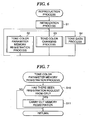
- FIG. 6 a flowchart of the reproduction process carried out by the tone generator hardware section 15 appearing in FIG. 2 is shown in FIG. 6 .
- step S1 an initialization process is carried out in which the tone generator hardware section 15 is initialized, for example various registers are reset or set to default values. Then, a tone color parameter memory registration process of step S2, a tone color changing process of step S3, and a tone data process of step s4 are carried out in parallel. The processes of these steps S2 to S4 are carried out repeatedly until the sequence data comes to an end or a stop instruction is issued, whereby reproduced musical tones are outputted based on the sequence data.
- steps S2 to S4 in FIG. 6 will be described with reference to FIGS. 7 to 9 .
- FIG. 7 a flowchart of the tone color parameter memory registration process of step S2 in FIG. 6 is shown in FIG. 7 .
- step S10 in FIG. 7 it is determined whether or not there has been a registration request from the CPU 10.
- the answer is determined to be "YES” and the process proceeds to step S11, where in step S11 tone color parameters read out from the RAM 11 are registered in the tone generator RAM 30a of the tone generator memory 30.
- step S10 the tone color parameter memory registration process ends, and the process returns to the steps after step S1. Moreover, in the case that it is determined in step S10 that there has not been a registration request from the CPU 10, again the tone color parameter memory registration process ends, and the process returns to the steps after step S1.
- FIG. 8 a flowchart of the tone color changing process of step S3 in FIG. 6 is shown in FIG. 8 .
- step S20 it is determined whether or not a tone color changing command has been received from the CPU 10.
- the CPU 10 has given a tone color changing command c to the controller 31 of the tone generator hardware section 15, the answer is determined to be "YES”, and the process proceeds to step S21 and step S22.
- step S21 the specified tone color parameter is read out from the tone generator RAM 30a or the tone generator ROM 30b, and is transmitted to the tone color cache memory 32a.
- step S22 which is carried out in parallel with step S21, the transmitted tone color parameter is received by the tone color cache memory 32a, and the tone color parameter for the specified channel is rewritten.
- FIG. 9 a flowchart of the tone data process of step S4 in FIG. 6 is shown in FIG. 9 .
- step S30 it is then determined whether or not key on has been set in the tone generator core 33 and the current state is key on.
- the answer is determined to be "YES” and the process proceeds to step S31, where the tone generator core 33 reads out the tone color parameter for the channel for which reproduction is to be carried out from the tone color cache memory 32a.
- step S32 data processing is carried out in which musical tone reproduction is carried out based on the read out tone color parameter and the control data that has been set in the tone generator core. Then, in step S33, the reproduced musical tone data is outputted (sounded). Once the process of step S33 has been completed, the tone data process ends, and the process returns to step S1. Moreover, in the case that it is determined in step S30 that the current state is not key on, again the tone data process ends, and the process returns to step S1.
- the output bit width may be narrowed somewhat so that a tone color parameter for one channel is sent to the tone generator core 33 with a few accesses. Even in this case, there will be virtually no effect in terms of sound generation break due to the time taken for the process in question.
- the musical tone reproducing apparatus of the present invention described above cannot only be applied to a mobile phone 1 as described above as the portable terminal apparatus, but may also be applied to a portable information apparatus capable of outputting musical tones, a portable personal computer capable of outputting musical tones, and so on.
- the music contents data may be reproduced in synchronization with text and/or image contents.
- the tone generator core 33 in the tone generator hardware section 15 may be comprised of a tone generator of frequency modulation type, i.e. an FM tone generator.
- a tone generator of frequency modulation type i.e. an FM tone generator.
- Such an FM tone generator utilizes harmonics generated by frequency modulation for synthesis of musical tones, and is capable of generating waveforms having harmonic components containing non-harmonic tones with relatively simple circuitry.
- Such an FM tone generator is also capable of generating a wide variety of musical tones from synthesized tones simulating natural musical instruments to electronic bleeps.
- Such an FM tone generator employs oscillators called "operators" that equivalently oscillate sine waves, for example the FM tone generator may be comprised of a first operator and a second operator that are cascaded with each other.
- such an FM tone generator may be constructed such that an output from an operator is itself fed back and inputted.
- the tone generator type of the tone generator core 33 of the tone generator hardware section 15 is not limited to the FM tone generator type, but rather may be a waveform memory tone generator (PCM tone generator or ADPCM tone generator) type, a physical model tone generator type, and so forth.
- PCM tone generator or ADPCM tone generator waveform memory tone generator
- a hardware tone generator using a DSP or the like may be employed.
- the musical tone reproducing apparatus has a tone generator memory as a general-purpose memory in which is registered at least a tone color parameter group comprising a freely chosen number of tone color parameters read out from the system storage means, a cache memory into which are inputted tone color parameters from the registered tone color parameter group at a predetermined data width from the tone generator memory and from which are outputted the inputted tone color parameters at a data width larger than the predetermined data width, and hence during changing of tone color, a tone color parameter that has been read out from the tone generator memory may be transferred into the cache memory.
- the tone color parameter group of a freely chosen number of tone color parameters has been registered in the tone generator memory, the need to transfer a tone color parameter from a system control means to the tone generator memory each time a tone color is to be changed can be removed as much as possible.
- the output bit width of the cache memory has been made to be large, the tone color parameter can be set into the tone generator means instantaneously. Consequently, even though the tone color parameters are stored in advance in the tone generator memory, the time taken for the tone color changing process can be shortened, and hence the occurrence of a break in sound generation during tone color changing can be prevented.
- the system control means reads out each of the tone color parameters from the tone generator memory by specifying a leading address of the predetermined addresses given to the tone color parameters, and hence the amount of data transfer between the system control means and the musical tone reproducing apparatus can be reduced.
Landscapes
- Engineering & Computer Science (AREA)
- Physics & Mathematics (AREA)
- Acoustics & Sound (AREA)
- Multimedia (AREA)
- Signal Processing (AREA)
- General Engineering & Computer Science (AREA)
- Electrophonic Musical Instruments (AREA)
- Telephone Function (AREA)
- Memory System Of A Hierarchy Structure (AREA)
- Mobile Radio Communication Systems (AREA)
Applications Claiming Priority (3)
| Application Number | Priority Date | Filing Date | Title |
|---|---|---|---|
| JP2001156622 | 2001-05-25 | ||
| JP2001156622A JP3642039B2 (ja) | 2001-05-25 | 2001-05-25 | 楽音再生装置および携帯端末装置 |
| PCT/JP2002/004950 WO2002097789A1 (en) | 2001-05-25 | 2002-05-22 | Musical sound reproducer and mobile terminal |
Publications (3)
| Publication Number | Publication Date |
|---|---|
| EP1391874A1 EP1391874A1 (en) | 2004-02-25 |
| EP1391874A4 EP1391874A4 (en) | 2007-12-19 |
| EP1391874B1 true EP1391874B1 (en) | 2008-10-15 |
Family
ID=19000613
Family Applications (1)
| Application Number | Title | Priority Date | Filing Date |
|---|---|---|---|
| EP02730687A Expired - Lifetime EP1391874B1 (en) | 2001-05-25 | 2002-05-22 | Musical sound reproducer and mobile terminal |
Country Status (9)
| Country | Link |
|---|---|
| US (1) | US7235733B2 (enExample) |
| EP (1) | EP1391874B1 (enExample) |
| JP (1) | JP3642039B2 (enExample) |
| KR (2) | KR20040004654A (enExample) |
| CN (1) | CN1535458B (enExample) |
| DE (1) | DE60229377D1 (enExample) |
| ES (1) | ES2312572T3 (enExample) |
| TW (1) | TW594671B (enExample) |
| WO (1) | WO2002097789A1 (enExample) |
Families Citing this family (3)
| Publication number | Priority date | Publication date | Assignee | Title |
|---|---|---|---|---|
| JP4309228B2 (ja) | 2003-10-22 | 2009-08-05 | Necインフロンティア株式会社 | IPテレフォニーシステム、VoIP端末及びそれらに用いる保留音・可聴音再生方法並びにそのプログラム |
| KR20050087368A (ko) | 2004-02-26 | 2005-08-31 | 엘지전자 주식회사 | 무선 단말기의 벨소리 처리 장치 |
| JP4475323B2 (ja) * | 2007-12-14 | 2010-06-09 | カシオ計算機株式会社 | 楽音発生装置、及びプログラム |
Family Cites Families (15)
| Publication number | Priority date | Publication date | Assignee | Title |
|---|---|---|---|---|
| US4887505A (en) * | 1987-06-26 | 1989-12-19 | Yamaha Corporation | Electronic musical instrument capable of performing an automatic accompaniment |
| JP2605434B2 (ja) * | 1989-12-09 | 1997-04-30 | ヤマハ株式会社 | 電子楽器のデータ発生装置 |
| US5345035A (en) * | 1992-07-10 | 1994-09-06 | Yamaha Corporation | Musical tone generating apparatus |
| JP3235409B2 (ja) * | 1995-06-07 | 2001-12-04 | ヤマハ株式会社 | ミュージックシステム、音源および楽音合成方法 |
| US5895449A (en) * | 1996-07-24 | 1999-04-20 | Yamaha Corporation | Singing sound-synthesizing apparatus and method |
| US5850051A (en) * | 1996-08-15 | 1998-12-15 | Yamaha Corporation | Method and apparatus for creating an automatic accompaniment pattern on the basis of analytic parameters |
| JP3572892B2 (ja) * | 1997-09-24 | 2004-10-06 | ヤマハ株式会社 | マルチ音源用楽音信号生成方法、マルチ音源装置及びプログラムを記録した媒体 |
| JPH11312085A (ja) | 1998-04-28 | 1999-11-09 | Hitachi Ltd | プロセッサ |
| JP2000029462A (ja) * | 1998-05-18 | 2000-01-28 | Sony Corp | 情報処理装置および情報処理方法、並びに提供媒体 |
| JP3541718B2 (ja) * | 1999-03-24 | 2004-07-14 | ヤマハ株式会社 | 楽音生成装置 |
| JP3603705B2 (ja) * | 1999-11-29 | 2004-12-22 | ヤマハ株式会社 | 音源回路およびそれを用いた電話端末装置 |
| JP3675362B2 (ja) * | 2000-08-18 | 2005-07-27 | ヤマハ株式会社 | 楽音生成装置および携帯端末装置 |
| JP3525901B2 (ja) | 2001-03-15 | 2004-05-10 | 松下電工株式会社 | 浴室ユニット |
| JP3700599B2 (ja) * | 2001-03-29 | 2005-09-28 | ヤマハ株式会社 | 音色選択装置及び方法 |
| JP3862061B2 (ja) * | 2001-05-25 | 2006-12-27 | ヤマハ株式会社 | 楽音再生装置および楽音再生方法ならびに携帯端末装置 |
-
2001
- 2001-05-25 JP JP2001156622A patent/JP3642039B2/ja not_active Expired - Fee Related
-
2002
- 2002-05-21 TW TW091110639A patent/TW594671B/zh not_active IP Right Cessation
- 2002-05-22 ES ES02730687T patent/ES2312572T3/es not_active Expired - Lifetime
- 2002-05-22 CN CN028148665A patent/CN1535458B/zh not_active Expired - Fee Related
- 2002-05-22 KR KR10-2003-7015395A patent/KR20040004654A/ko not_active Ceased
- 2002-05-22 WO PCT/JP2002/004950 patent/WO2002097789A1/ja not_active Ceased
- 2002-05-22 DE DE60229377T patent/DE60229377D1/de not_active Expired - Lifetime
- 2002-05-22 EP EP02730687A patent/EP1391874B1/en not_active Expired - Lifetime
- 2002-05-22 KR KR1020067012256A patent/KR100633804B1/ko not_active Expired - Fee Related
-
2003
- 2003-11-25 US US10/722,254 patent/US7235733B2/en not_active Expired - Fee Related
Also Published As
| Publication number | Publication date |
|---|---|
| KR20060084861A (ko) | 2006-07-25 |
| EP1391874A4 (en) | 2007-12-19 |
| KR20040004654A (ko) | 2004-01-13 |
| ES2312572T3 (es) | 2009-03-01 |
| JP3642039B2 (ja) | 2005-04-27 |
| CN1535458A (zh) | 2004-10-06 |
| WO2002097789A1 (en) | 2002-12-05 |
| CN1535458B (zh) | 2010-05-05 |
| EP1391874A1 (en) | 2004-02-25 |
| JP2002351465A (ja) | 2002-12-06 |
| US20040159217A1 (en) | 2004-08-19 |
| US7235733B2 (en) | 2007-06-26 |
| DE60229377D1 (de) | 2008-11-27 |
| KR100633804B1 (ko) | 2006-10-16 |
| TW594671B (en) | 2004-06-21 |
Similar Documents
| Publication | Publication Date | Title |
|---|---|---|
| KR100460525B1 (ko) | 휴대전화단말에 적용 가능한 음악재생장치 | |
| KR100450871B1 (ko) | 휴대전화 및 음악 재생방법 | |
| JP2001060993A (ja) | 電話端末装置および通信方法 | |
| US7102070B2 (en) | Musical tone reproducing apparatus and method and portable terminal apparatus | |
| US7247784B2 (en) | Musical sound generator, portable terminal, musical sound generating method, and storage medium | |
| EP1560196B1 (en) | Music reproducing apparatus, music reproducing method and telephone terminal device | |
| KR100477306B1 (ko) | 휴대 전화 | |
| JP3722015B2 (ja) | 楽音生成装置 | |
| EP1391874B1 (en) | Musical sound reproducer and mobile terminal | |
| EP1391872A1 (en) | Telephone terminal apparatus | |
| JP3982532B2 (ja) | 楽音再生装置および携帯端末装置 | |
| JP3279293B2 (ja) | 楽曲再生装置、楽曲再生機能を備える携帯電話装置および楽曲再生方法 | |
| JP3279298B2 (ja) | 楽曲再生装置、楽曲再生機能を備える携帯電話装置、および楽曲再生方法 | |
| HK1066086A (en) | Musical sound reproducer and mobile terminal | |
| JP2005229511A (ja) | 楽音生成装置 | |
| JP2005107547A (ja) | 楽音生成装置および携帯端末装置 | |
| JP2005234208A (ja) | 楽曲再生装置及び携帯端末装置 | |
| HK1061297A (en) | Telephone terminal apparatus |
Legal Events
| Date | Code | Title | Description |
|---|---|---|---|
| PUAI | Public reference made under article 153(3) epc to a published international application that has entered the european phase |
Free format text: ORIGINAL CODE: 0009012 |
|
| 17P | Request for examination filed |
Effective date: 20031119 |
|
| AK | Designated contracting states |
Kind code of ref document: A1 Designated state(s): AT BE CH CY DE DK ES FI FR GB GR IE IT LI LU MC NL PT SE TR |
|
| AX | Request for extension of the european patent |
Extension state: AL LT LV MK RO SI |
|
| RAP1 | Party data changed (applicant data changed or rights of an application transferred) |
Owner name: YAMAHA CORPORATION |
|
| A4 | Supplementary search report drawn up and despatched |
Effective date: 20071121 |
|
| RIC1 | Information provided on ipc code assigned before grant |
Ipc: G10H 1/24 20060101AFI20021211BHEP |
|
| GRAP | Despatch of communication of intention to grant a patent |
Free format text: ORIGINAL CODE: EPIDOSNIGR1 |
|
| GRAS | Grant fee paid |
Free format text: ORIGINAL CODE: EPIDOSNIGR3 |
|
| GRAA | (expected) grant |
Free format text: ORIGINAL CODE: 0009210 |
|
| AK | Designated contracting states |
Kind code of ref document: B1 Designated state(s): DE ES FR GB IT |
|
| REG | Reference to a national code |
Ref country code: GB Ref legal event code: FG4D |
|
| REF | Corresponds to: |
Ref document number: 60229377 Country of ref document: DE Date of ref document: 20081127 Kind code of ref document: P |
|
| REG | Reference to a national code |
Ref country code: ES Ref legal event code: FG2A Ref document number: 2312572 Country of ref document: ES Kind code of ref document: T3 |
|
| PLBE | No opposition filed within time limit |
Free format text: ORIGINAL CODE: 0009261 |
|
| STAA | Information on the status of an ep patent application or granted ep patent |
Free format text: STATUS: NO OPPOSITION FILED WITHIN TIME LIMIT |
|
| 26N | No opposition filed |
Effective date: 20090716 |
|
| PGFP | Annual fee paid to national office [announced via postgrant information from national office to epo] |
Ref country code: ES Payment date: 20110617 Year of fee payment: 10 |
|
| PGFP | Annual fee paid to national office [announced via postgrant information from national office to epo] |
Ref country code: IT Payment date: 20110520 Year of fee payment: 10 |
|
| PG25 | Lapsed in a contracting state [announced via postgrant information from national office to epo] |
Ref country code: IT Free format text: LAPSE BECAUSE OF NON-PAYMENT OF DUE FEES Effective date: 20120522 |
|
| PGFP | Annual fee paid to national office [announced via postgrant information from national office to epo] |
Ref country code: GB Payment date: 20130522 Year of fee payment: 12 Ref country code: DE Payment date: 20130515 Year of fee payment: 12 |
|
| PGFP | Annual fee paid to national office [announced via postgrant information from national office to epo] |
Ref country code: FR Payment date: 20130531 Year of fee payment: 12 |
|
| REG | Reference to a national code |
Ref country code: ES Ref legal event code: FD2A Effective date: 20131030 |
|
| PG25 | Lapsed in a contracting state [announced via postgrant information from national office to epo] |
Ref country code: ES Free format text: LAPSE BECAUSE OF NON-PAYMENT OF DUE FEES Effective date: 20120523 |
|
| REG | Reference to a national code |
Ref country code: DE Ref legal event code: R119 Ref document number: 60229377 Country of ref document: DE |
|
| GBPC | Gb: european patent ceased through non-payment of renewal fee |
Effective date: 20140522 |
|
| REG | Reference to a national code |
Ref country code: DE Ref legal event code: R119 Ref document number: 60229377 Country of ref document: DE Effective date: 20141202 |
|
| REG | Reference to a national code |
Ref country code: FR Ref legal event code: ST Effective date: 20150130 |
|
| PG25 | Lapsed in a contracting state [announced via postgrant information from national office to epo] |
Ref country code: DE Free format text: LAPSE BECAUSE OF NON-PAYMENT OF DUE FEES Effective date: 20141202 |
|
| PG25 | Lapsed in a contracting state [announced via postgrant information from national office to epo] |
Ref country code: GB Free format text: LAPSE BECAUSE OF NON-PAYMENT OF DUE FEES Effective date: 20140522 Ref country code: FR Free format text: LAPSE BECAUSE OF NON-PAYMENT OF DUE FEES Effective date: 20140602 |