EP1391344B1 - Bedienanordnung für einen Fahrzeugsitz - Google Patents
Bedienanordnung für einen Fahrzeugsitz Download PDFInfo
- Publication number
- EP1391344B1 EP1391344B1 EP03017573A EP03017573A EP1391344B1 EP 1391344 B1 EP1391344 B1 EP 1391344B1 EP 03017573 A EP03017573 A EP 03017573A EP 03017573 A EP03017573 A EP 03017573A EP 1391344 B1 EP1391344 B1 EP 1391344B1
- Authority
- EP
- European Patent Office
- Prior art keywords
- handrail
- operating
- seat
- seat cushion
- arrangement according
- Prior art date
- Legal status (The legal status is an assumption and is not a legal conclusion. Google has not performed a legal analysis and makes no representation as to the accuracy of the status listed.)
- Expired - Lifetime
Links
Images



Classifications
-
- B—PERFORMING OPERATIONS; TRANSPORTING
- B60—VEHICLES IN GENERAL
- B60N—SEATS SPECIALLY ADAPTED FOR VEHICLES; VEHICLE PASSENGER ACCOMMODATION NOT OTHERWISE PROVIDED FOR
- B60N2/00—Seats specially adapted for vehicles; Arrangement or mounting of seats in vehicles
- B60N2/02—Seats specially adapted for vehicles; Arrangement or mounting of seats in vehicles the seat or part thereof being movable, e.g. adjustable
- B60N2/0224—Non-manual adjustments, e.g. with electrical operation
- B60N2/0226—User interfaces specially adapted for seat adjustment
- B60N2/0228—Hand-activated mechanical switches
-
- B—PERFORMING OPERATIONS; TRANSPORTING
- B60—VEHICLES IN GENERAL
- B60N—SEATS SPECIALLY ADAPTED FOR VEHICLES; VEHICLE PASSENGER ACCOMMODATION NOT OTHERWISE PROVIDED FOR
- B60N2/00—Seats specially adapted for vehicles; Arrangement or mounting of seats in vehicles
- B60N2/02—Seats specially adapted for vehicles; Arrangement or mounting of seats in vehicles the seat or part thereof being movable, e.g. adjustable
- B60N2/0224—Non-manual adjustments, e.g. with electrical operation
- B60N2/0226—User interfaces specially adapted for seat adjustment
- B60N2/0229—User interfaces specially adapted for seat adjustment characterised by the shape, e.g. switches having cushion or backrest shape
Definitions
- the invention relates to an operating arrangement for a vehicle seat specified in the preamble of claim 1. Art.
- the US 2002/0050730 A and the DE 35 17 505 A each show an operating order for vehicle seats, in which the actuating elements are integrated in one side of the seat cushion.
- control panel includes a plurality of spaced-apart seat adjustment actuators which are to be distinguished by sensing their location or shape.
- the actuating elements protrude laterally from the control panel and are assigned by a different form of a specific function.
- the invention has for its object to provide a vehicle seat of the type mentioned, in which at least one actuator is particularly ergonomic and user-friendly to operate.
- the control panel is designed as a handgrip that can be scanned lengthwise, in which all the actuating elements of the handrail are arranged largely submerged in it. Due to this design of the control element as a handrail and the recessed arrangement of the actuators therein, the hand of the seat occupant can be moved very quickly along the handrail without the actuators protruding disturbing from the control.
- the assignment of certain functions to the corresponding actuators is very well ensured by their different shape.
- the different design of the actuators is achieved by a different shape, materials, surfaces, material strengths or the like.
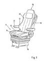
- FIG. 1 is a schematic perspective view of a swing seat of a commercial vehicle, in particular a truck shown, which includes a vehicle-fixed seat frame 10.
- a seat part 12 with a seat cushion 14 is supported on the seat base frame 10 in a height-adjustable manner by means of, for example, a hydraulically or pneumatically operated spring and / or damper unit.
- a backrest 16 is pivotally attached, which essentially comprises a rear support member 18, a pad 20 and side armrests 22.
- From an operating manual is a designed as a length scannable handrail 24, further explained in more detail below elongated control panel recognizable, which extends both laterally next to the seat cushion 14 of the vehicle seat and in front of the seat cushion 14.
- the handrail 24 extends over a substantial portion of its length approximately horizontally at the level of the lower end of the seat cushion. In a rear part near the backrest 16 of the handrail 16 is angled upwards.
- the handrail 24 includes a plurality of spaced-apart actuators 26-36, which are to be distinguished from one another by sensing their position or shape. The different design of the actuators is achieved by a different shape, materials, surfaces, material strengths or the like.
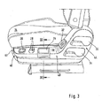
- Fig. 1 enlarged, fragmentary and schematic perspective view is shown on the control panel 24, it can be seen that the handrail 24 extends over the entire length of the seat cushion and that all actuators 26-36 of the handrail 24 are arranged largely sunk in this.
- the handrail 24 has an upwardly facing sensing track 38 and a side facing away from the seat cushion 14 lateral sensing track 40, wherein the upward facing sensing track 38 seen from the front is inclined laterally and sloping in the outward direction, whereby this includes an obtuse angle with the lateral sensing path 40.
- an upwardly angled side portion 44 of the side sensing path 40 is formed, which is widened to a large-sized sub-panel with the actuators 34 and 36.
- the upwardly facing sensing track 38 has over its length both in the horizontally extending portion of the handrail 24 as well as in the upwardly angled portion of the handrail 24 has a substantially constant width.
- the handrail 24 includes one associated with Figure 4 explained in more detail conveniently arranged in the handrail 24 arranged handle plate 26 which is arranged over the corner in the upwardly facing and the side sensing track 38,40 and serves to adjust the height of the vibrating seat.
- handle plate 26 which is arranged over the corner in the upwardly facing and the side sensing track 38,40 and serves to adjust the height of the vibrating seat.
- the actuator is intended to perform the most frequently Seat used will be arranged so that the hand - the resting at rest without effort hanging arm of the seat occupant - can reach the actuator 26 by the shortest route.
- the most commonly used feature is generally the seat height adjustment.
- a switch element 28 for the seat heating or the like is integrated into the upwardly directed sensing track 38. In this area can also be a switch element for the heating and air conditioning of the driver's cab be provided.
- a switch element 30 for rapid lowering of the here pneumatically sprung seat in the upwardly facing sensing track 38 is arranged.
- the occupant When getting out of the cab, the occupant is generally supported in a region of the seat cushion 14 arranged above the switch element 30, so that the occupant quickly and ergonomically reaches the switch element 30 for rapid lowering with the hand already in this area before getting out ,
- a switch block 32 is provided with a plurality of switching elements in the upwardly directed sensing path, with reference to Figure 6 will be explained in detail.
- a switch block 32 is provided with a plurality of switching elements in the upwardly directed sensing path, with reference to Figure 6 will be explained in detail.
- two pivotable about an approximately horizontal axis handle flaps 34,36 which are associated with the seat tilt adjustment and the backrest tilt adjustment.
- the height extent of the arranged within an associated trough grip flaps 34,36 is significantly increased in the rear end region relative to the vertical extent in the front end region, so that below the respective front portion of a recessed grip 48 is formed for actuation.
- FIG 4 is a schematic, partial and enlarged sectional view through the handrail 24 of the seat part in the region of the hand grip 24 arranged grip plate 26 along the line IV-IV in Figure 3 shown.
- the switch element 28 Seen in the vehicle longitudinal direction in front of the handle plate 26, the switch element 28 is arranged for the seat heating. It can be seen that the actuators of the handrail 24 in are essentially sunk in this, so that the hand can be guided without much resistance along the control panel.
- the handle plate 26 is arranged at an angle in the upwardly facing and the lateral Tastbahn 38,40 and has for better detection and handling on top and bottom of an engagement recess 50,52, wherein the raising or lowering of the handle plate 26 to a lifting or Lowering the seat leads.
- an engagement recess 54 is recessed from the handrail 24.
- FIG. 5 is the swing seat shown in front view, in which the handrail 24 passes from its side of the seat cushion 14 extending length range under soft curve in a front of the seat cushion 14 extending length range.
- a further actuating element 56 for adjusting the seat cushioning is integrated, the damping being changed by raising or lowering the actuating element 56.
- the actuating element 56 comprises a web-like grip portion 58, which extends to the front only to the extent that the actuating element 56 is arranged largely sunk in the handrail 24.
- the actuator 56 is relatively narrow, so that the hand can be performed without much resistance along the control panel.
- a further actuator 60 is arranged for seat cushion depth adjustment and the seat base 10, a locking bracket 62 is provided for longitudinal adjustment of the seat.
- FIG. 6 is shown in plan view of the upwardly angled longitudinal portion of the handrail 24 with the upward facing Tastbahn 38, in which the switch block 32 is integrated with a plurality of switching elements 64,66,68.
- the middle lower switch 64 and the middle upper switch 66 are formed as pivotable about the respective axis A rocker switch, which for adjusting the seat cushion hardness of the associated Seat cushion 14 of the seat part 12 and the backrest 16 and the so-called. Lumbar support of the backrest 16 are used.
- Two laterally over the length of the switch block 32 extending narrow switch elements 68 are connected to each other via a web 70 and pivotable about an axis W together. As a result, the pad hardness of sidewalls 72 ( Fig.
- the switch block 32 controls here on pneumatic way - ie via appropriate control valves - the corresponding pad.
- the control functions of the actuators 26-36, 58-62 can be done either in pneumatic, hydraulic, electrical or mechanical manner.
Landscapes
- Engineering & Computer Science (AREA)
- Human Computer Interaction (AREA)
- Aviation & Aerospace Engineering (AREA)
- Transportation (AREA)
- Mechanical Engineering (AREA)
- Seats For Vehicles (AREA)
- Forklifts And Lifting Vehicles (AREA)
- Passenger Equipment (AREA)
- Chair Legs, Seat Parts, And Backrests (AREA)
Description
- Die Erfindung betrifft eine Bedienanordnung für einen Fahrzeugsitz der im Oberbegriff des Patentanspruchs 1 angegebenen Art.
- In der
JP 09 245550 A DE 28 46 927 A und derJP 2000 153730 A - Die
US 2002/0050730 A und dieDE 35 17 505 A zeigen jeweils eine Bedienungsanordnung für Fahrzeugsitze, bei welcher die Betätigungselemente in einer Seite des Sitzkissens integriert sind. - Des Weiteren ist in der
DE 94 00 606 U eine Bedienungsanordnung für Fahrzeugsitze bekannt, bei welcher die Betätigungselemente in dem Schaumstoff einer der seitlichen Abstützungen integriert sind. - Schließlich ist aus der
DE 44 05 566 A1 bereits eine Bedienanordnung mit einem länglichen Bedienfeld als bekannt zu entnehmen, welches abgewinkelt ist und sich seitlich neben dem Sitzkissen und der Rückenlehne des Fahrzeugsitzes erstreckt. Das Bedienfeld.umfasst mehrere im Abstand voneinander angeordnete Betätigungselemente zur Sitzeinstellung, welche durch Ertasten ihrer Lage oder Gestalt zu unterscheiden sind. Dabei ragen die Betätigungselemente seitlich von dem Bedienfeld ab und sind durch eine unterschiedliche Form einer bestimmten Funktion zuzuordnen. - Der Erfindung liegt die Aufgabe zugrunde, einen Fahrzeugsitz der eingangs genannten Art zu schaffen, bei welchem wenigstens ein Betätigungselement besonders ergonomisch und benutzerfreundlich zu betätigen ist.
- Die erfindungsgemäße Lösung dieser Aufgabe ergibt sich aus den Merkmalen des Hauptanspruchs. Vorteilhafte Ausgestaltungen der Erfindung sind den übrigen Ansprüchen zu entnehmen.
- Bei dem Fahrzeugsitz ist das Bedienfeld als ein der Länge nach abtastbarer Handlauf ausgebildet, bei dem alle Betätigungselemente des Handlaufes weitgehend in diesem versenkt angeordnet sind. Durch diese Ausbildung des Bedienelements als Handlauf und die versenkte Anordnung der Betätigungselemente darin kann die Hand des Sitzinsassen sehr schnell entlang des Handlaufes bewegt werden, ohne dass die Betätigungselemente störend aus dem Bedienelement herausragen. Dabei ist die Zuordnung von bestimmten Funktionen zu den entsprechenden Betätigungselementen durch deren unterschiedliche Gestalt sehr gut gewährleistet. Die unterschiedliche Gestaltung der Betätigungselemente wird dabei durch eine unterschiedliche Formgebung, Materialien, Oberflächen, Materialfestigkeiten oder dgl. erreicht.
- Durch die versenkte Anordnung der Betätigungselemente in dem Handlauf ist außerdem eine Fehlbedienung besser vermieden, da die entlang des Handlaufs geführte Hand nicht gegen erhaben abragende Betätigungselemente stoßen kann.
- Weitere Vorteile, Merkmale und Einzelheiten der Erfindung ergeben sich aus der nachfolgenden Beschreibung eines bevorzugten Ausführungsbeispieles sowie anhand der Zeichnungen; diese zeigen in
- Fig.1
- eine schematische Perspektivansicht auf einen Schwingsitz eines Nutzfahrzeuges mit der Bedienanord-nung nach der Erfindung;
- Fig.2,3
- jeweils eine gegenüber
Fig.1 vergrößerte, ausschnittsweise und schematische Perspektivansicht auf das als Handlauf ausgebildete Bedienfeld nach der Erfindung; - Fig.4
- eine schematische, ausschnittsweise und vergrößerte Schnittansicht durch ein Betätigungselement des Handlaufs entlang der Linie IV-IV in
Fig.3 ; - Fig.5
- eine Vorderansicht auf den Schwingsitz gemäß den Figuren 1 bis 4, bei dem der seitlich des Sitzkissens angeordnete Handlauf in einen vor dem Sitzkissen verlaufenden Längenbereich übergeht; und in
- Fig.6
- eine Draufsicht auf ein weiteres Betätigungselement des erfindungsgemäßen Bedienfeldes.
- In
Fig. 1 ist in schematischer Perspektivansicht ein Schwingsitz eines Nutzfahrzeuges, insbesondere eines Lastkraftwagens dargestellt, welcher ein fahrzeugfestes Sitzuntergestell 10 umfasst. Ein Sitzteil 12 mit einem Sitzkissen 14 ist über eine beispielsweise hydraulisch oder pneumatisch betriebene Feder- und/oder Dämpfereinheit höhenverstellbar am Sitzuntergestell 10 abgestützt. An dem Sitzteil 12 ist eine Rückenlehne 16 schwenkbar angelagert, welche im wesentlichen ein rückwärtiges Tragteil 18, ein Polster 20 und seitliche Armlehnen 22 umfasst. Von einer Bedienungsanordnung ist ein als der Länge nach abtastbarer Handlauf 24 gestaltetes, im weiteren noch näher erläutertes längliches Bedienfeld erkennbar, das sich hier sowohl seitlich neben dem Sitzkissen 14 des Fahrzeugsitzes als auch vor dem Sitzkissen 14 erstreckt. In dem hier gezeigten Ausführungsbeispiel verläuft der Handlauf 24 über einen erheblichen Teilbereich seiner Länge etwa horizontal auf Höhe des unteren Endes des Sitzkissens. In einem hinteren Teil nahe der Rückenlehne 16 ist der Handlauf 16 nach oben abgewinkelt. Der Handlauf 24 umfasst eine Mehrzahl von im Abstand zueinander angeordneten Betätigungselementen 26-36, welche durch Ertasten ihrer Lage oder Gestalt voneinander zu unterscheiden sind. Die unterschiedliche Gestaltung der Betätigungselemente wird dabei durch eine unterschiedliche Formgebung, Materialien, Oberflächen, Materialfestigkeiten oder dgl. erreicht. - In Zusammenschau mit den
Figuren 2 und3 , in welchen jeweils eine gegenüberFig. 1 vergrößerte, ausschnittsweise und schematische Perspektivansicht auf das Bedienfeld 24 dargestellt ist, wird ersichtlich, dass sich der Handlauf 24 über die gesamte Länge des Sitzkissens erstreckt und dass alle Betätigungselemente 26-36 des Handlaufes 24 weitgehend in diesem versenkt angeordnet sind. Der Handlauf 24 hat eine nach oben gewandte Tastbahn 38 und eine vom Sitzkissen 14 abgewandte seitliche Tastbahn 40, wobei die nach oben gewandte Tastbahn 38 von vorne gesehen seitlich geneigt und in Richtung nach außen abfallend verläuft, wodurch diese mit der seitlichen Tastbahn 40 einen stumpfen Winkel einschließt. Durch den im Übergangsbereich vom Sitzkissen 14 zur Sitzlehne 16 nach oben abgewinkelten Handlauf 24 ist ein nach oben abgewinkelter Seitenbereich 44 der seitlichen Tastbahn 40 gebildet, welcher zu einem großformatigen Teilbedienfeld mit den Betätigungselementen 34 und 36 verbreitert ist. Die nach oben gewandte Tastbahn 38 weist über ihre Länge sowohl im horizontal verlaufenden Abschnitt des Handlaufs 24 wie auch im nach oben abgewinkelten Abschnitt des Handlaufs 24 eine im wesentlichen konstante Breite auf. - Im einzelnen umfasst der Handlauf 24 eine im Zusammenhang mit
Fig.4 noch näher erläuterte griffgünstig im Handlauf 24 angeordnete Griffplatte 26, welche über Eck in der nach oben gewandten und der seitlichen Tastbahn 38,40 angeordnet ist und zur Höheneinstellung des Schwingsitzes dient. Unter griffgünstig im Handlauf 24 angeordnet ist dabei folgendes zu verstehen:
Sitzt ein Insasse auf gewöhnlich vorgesehene aufrechte Weise in dem Fahrzeugsitz und lässt er seinen Arm in Fallrichtung gerade nach unten hängen, so befinden sich seine Hand in unmittelbarer Zugriffsnähe zu der Griffplatte 26. Mit anderen Worten soll das Betätigungselement derjenigen Funktion, welche am häufigsten bei einem Sitz gebraucht wird so angeordnet sein, dass die Hand - des im Ruhezustand ohne Kraftaufwand hängenden Arms des Sitzinsassen - auf kürzestem Weg das Betätigungselement 26 erreichen kann. Bei einem Schwingsitz ist die am häufigsten benutze Funktion im allgemeinen die Sitzhöheneinstellung. - Vor der Griffplatte 26 ist in die nach oben gewandte Tastbahn 38 ein Schalterelement 28 für die Sitzheizung oder dgl. integriert. In diesem Bereich kann auch ein Schalterelement für die Heizung und Klimatisierung der Fahrerkabine vorgesehen sein.
- Nahe des Eckbereichs 46 des Handlaufes 24, in welchem dieser von seinem seitlich des Sitzkissens 14 verlaufenden Längenbereich in den vor dem Sitzkissen 14 verlaufenden Längenbereich übergeht, ist ein Schalterelement 30 zur Schnellabsenkung des hier pneumatisch gefederten Sitzes in der nach oben gewandten Tastbahn 38 angeordnet. Beim Aussteigen aus dem Fahrerhaus stützt sich der Insasse im allgemeinen in einem oberhalb des Schalterelementes 30 angeordneten Bereich des Sitzkissens 14 ab, so dass der Insasse vor dem Aussteigen das Schalterelement 30 zur Schnellabsenkung mit der sich bereits in diesem Bereich befindenden Hand sehr schnell und ergonomisch erreicht.
- Im nach oben abgewinkelten Längenabschnitt des Handlaufs 24 ist in der nach oben gewandten Tastbahn ein Schalterblock 32 mit mehreren Schaltelementen vorgesehen, der unter Bezugnahme auf
Fig.6 noch detailliert erläutert werden wird. Schließlich sind in denFiguren 2 und3 im großformatigen Teilbedienfeld 44 zwei um eine etwa horizontale Achse verschwenkbare Griffklappen 34,36 angeordnet, welche der Sitzneigungseinstellung und der Rückenlehnenneigungseinstellung zugeordnet sind. Die Höhenerstreckung der innerhalb einer zugeordneten Mulde angeordneten Griffklappen 34,36 ist im hinteren Endbereich gegenüber der Höhenerstreckung im vorderen Endbereich deutlich vergrößert, so dass unterhalb des jeweiligen vorderen Teilbereichs eine Eingriffsmulde 48 zur Betätigung gebildet ist. - In
Fig.4 ist eine schematische, ausschnittsweise und vergrößerte Schnittansicht durch den Handlauf 24 des Sitzteils im Bereich der griffgünstig im Handlauf 24 angeordneten Griffplatte 26 entlang der Linie IV-IV inFig.3 dargestellt. In Fahrzeuglängsrichtung gesehen vor der Griffplatte 26 ist das Schalterelement 28 für die Sitzheizung angeordnet. Es ist ersichtlich, dass die Betätigungselemente des Handlaufes 24 im wesentlichen in diesem versenkt angeordnet sind, so dass die Hand ohne großen Widerstand entlang des Bedienfeldes geführt werden kann. Die Griffplatte 26 ist über Eck in der nach oben gewandten und der seitlichen Tastbahn 38,40 angeordnet und weist zur besseren Erkennung und Handhabbarkeit ober- und unterseitig eine Eingriffsvertiefung 50,52 auf, wobei das Anheben bzw. Absenken der Griffplatte 26 zu einem Anheben bzw. Absenken des Sitzes führt. Um die Eingriffsvertiefung 52 an der Unterseite der Griffplatte 26 erreichen zu können, ist aus dem Handlauf 24 eine Eingriffsmulde 54 ausgespart. - In
Fig.5 ist der Schwingsitz in Vorderansicht dargestellt, bei dem der Handlauf 24 von seinem seitlich des Sitzkissens 14 verlaufenden Längenbereich unter weicher Rundung in einen vor dem Sitzkissen 14 verlaufenden Längenbereich übergeht. Innerhalb des vor dem Sitzkissen 14 verlaufenden Längenbereichs des Handlaufs 24 ist ein weiteres Betätigungselement 56 zur Einstellung der Sitzdämpfung integriert, wobei die Dämpfung durch Anheben bzw. Absenken des Betätigungselements 56 verändert wird. Das Betätigungselement 56 umfasst einen stegartigen Griffabschnitt 58, der nach vorne lediglich soweit reicht, dass das Betätigungselement 56 weitgehend versenkt in dem Handlauf 24 angeordnet ist. Außerdem ist das Betätigungselement 56 relativ schmal bemessen, so dass die Hand ohne großen Widerstand entlang des Bedienfeldes geführt werden kann. Oberhalb des Handlaufs 24 ist ein weiteres Betätigungselement 60 zur Sitzkissentiefeneinstellung angeordnet und am Sitzuntergestell 10 ist ein Rastbügel 62 zur Längseinstellung des Sitzes vorgesehen. - In
Fig.6 ist in Draufsicht der nach oben abgewinkelte Längenabschnitt des Handlaufs 24 mit der nach oben gewandten Tastbahn 38 gezeigt, in welcher der Schalterblock 32 mit mehreren Schaltelementen 64,66,68 integriert ist. Dabei sind der mittlere untere Schalter 64 und der mittlere obere Schalter 66 als um die jeweilige Achse A schwenkbare Wippenschalter ausgebildet, welche zur Einstellung der Sitzkissenhärte des zugeordneten Sitzkissens 14 des Sitzteils 12 und der Rückenlehne 16 bzw. der sog. Lordosenstütze der Rückenlehne 16 dienen. Zwei seitlich über die Länge des Schalterblocks 32 verlaufende schmale Schalterelemente 68 sind über einen Steg 70 miteinander verbunden und gemeinsam um eine Achse W verschwenkbar. Hierdurch ist die Polsterhärte von Seitenwangen 72 (Fig. 1 ) des Sitzteils 12 und/oder der Rückenlehne 16 veränderbar. Der Schalterblock 32 steuert hier auf pneumatischem Weg - also über entsprechende Steuerventile - die entsprechenden Polster. Je nach Anwendung können die Steuerfunktionen der Betätigungselemente 26-36, 58-62 wahlweise auf pneumatische, hydraulische, elektrische oder mechanische Weise erfolgen.
Claims (8)
- Bedienanordnung für einen Fahrzeugsitz mit einem länglichen Bedienfeld (24), das seitlich neben dem Sitzkissen (14) des Fahrzeugsitzes angeordnet ist und mehrere im Abstand voneinander angeordneten Betätigungselemente (26-36) aufweist, wobei die Betätigungselemente (26-36) durch Ertasten ihrer Lage oder Gestalt zu unterscheiden sind, wobei das Bedienfeld als ein der Länge nach abtastbarer Handlauf (24) ausgebildet ist, der sich über die überwiegende Länge des Sitzkissens (14) erstreckt, wobei alle Betätigungselemente (26-36) des Handlaufes (24) weitgehend in diesem versenkt angeordnet sind, und wobei der Handlauf (24) eine nach oben gewandte Tastbahn (38) und eine vom Sitzkissen (14) abgewandte seitliche Tastbahn (40) aufweist,
dadurch gekennzeichnet, dass
eines (26) der im Handlauf (24) angeordneten Betätigungselemente (26-36) über Eck in der nach oben gewandten und der seitlichen Tastbahn (38, 40) angeordnet ist. - Bedienanordnung nach Anspruch 1,
dadurch gekennzeichnet, dass
die nach oben gewandte Tastbahn (38) im Querschnitt gesehen seitlich geneigt verläuft, wodurch diese mit der seitlichen Tastbahn (40) einen stumpfen Winkel einschließt. - Bedienanordnung nach Anspruch 1 oder 2,
dadurch gekennzeichnet, dass
der Handlauf (24) im Übergangsbereich vom Sitzkissen (14) zur Rückenlehne (16) nach oben abgewinkelt ist. - Bedienanordnung nach Anspruch 1,
dadurch gekennzeichnet, dass
die nach oben gewandte Tastbahn (38) über ihre Länge eine im Wesentlichen konstante Breite aufweist. - Bedienanordnung nach Anspruch 1,
dadurch gekennzeichnet, dass
das griffgünstig im Handlauf (24) angeordnete Betätigungselement (26) an der Unterseite eine Eingriffsvertiefung (52) aufweist. - Bedienanordnung nach Anspruch 3,
dadurch gekennzeichnet, dass
im nach oben abgewinkelten Längenabschnitt der nach oben gewandten Tastbahn (38) ein Schalterblock (32) mit mehreren Schaltelementen (64, 66, 68) integriert ist. - Bedienanordnung nach Anspruch 1,
dadurch gekennzeichnet, dass
der Handlauf (24) von seinem seitlich des Sitzkissens (14) verlaufenden Längenbereich unter weicher Rundung in einen vor dem Sitzkissen (14) verlaufenden Längenbereich übergeht. - Bedienanordnung nach Anspruch 1,
dadurch gekennzeichnet, dass
die Bedienanordnung einem Schwingsitz eines Nutzfahrzeuges zugeordnet ist und ein Betätigungselement (30) für eine Schnellabsenkung des Schwingsitzes umfasst.
Applications Claiming Priority (2)
| Application Number | Priority Date | Filing Date | Title |
|---|---|---|---|
| DE10238656 | 2002-08-23 | ||
| DE10238656A DE10238656A1 (de) | 2002-08-23 | 2002-08-23 | Bedienanordnung für einen Fahrzeugsitz |
Publications (3)
| Publication Number | Publication Date |
|---|---|
| EP1391344A2 EP1391344A2 (de) | 2004-02-25 |
| EP1391344A3 EP1391344A3 (de) | 2005-06-08 |
| EP1391344B1 true EP1391344B1 (de) | 2009-12-30 |
Family
ID=30775526
Family Applications (1)
| Application Number | Title | Priority Date | Filing Date |
|---|---|---|---|
| EP03017573A Expired - Lifetime EP1391344B1 (de) | 2002-08-23 | 2003-08-07 | Bedienanordnung für einen Fahrzeugsitz |
Country Status (3)
| Country | Link |
|---|---|
| EP (1) | EP1391344B1 (de) |
| AT (1) | ATE453534T1 (de) |
| DE (2) | DE10238656A1 (de) |
Families Citing this family (9)
| Publication number | Priority date | Publication date | Assignee | Title |
|---|---|---|---|---|
| DE102008010372B3 (de) * | 2008-02-21 | 2009-04-02 | Faurecia Autositze Gmbh | Fahrzeugsitz mit einem Bediensystem |
| DE102008034156A1 (de) | 2008-07-22 | 2010-01-28 | Volkswagen Ag | Blendenanordnung für Bedienanordnungen eines Fahrzeugs und Verfahren zur Herstellung einer solchen Blendenanordnung |
| JP5229832B2 (ja) * | 2010-12-22 | 2013-07-03 | トヨタ紡織株式会社 | 車両用シート |
| DE102012012983B4 (de) | 2012-06-29 | 2014-04-24 | Isringhausen Gmbh & Co. Kg | Fahrzeugsitz mit Rückenlehnenneigungseinstellung sowie Schulteranpassung |
| CN105829166B (zh) * | 2013-12-26 | 2017-10-24 | 日本发条株式会社 | 车辆用座椅 |
| JP6276741B2 (ja) * | 2015-11-20 | 2018-02-07 | テイ・エス テック株式会社 | 乗物用シート |
| US10682927B1 (en) * | 2019-03-26 | 2020-06-16 | Seats Incorporated | Vehicle seat control assembly |
| US12184276B2 (en) * | 2020-07-03 | 2024-12-31 | Ts Tech Co., Ltd. | Interior article for conveyance |
| DE102024002484A1 (de) | 2024-08-01 | 2026-02-05 | Mercedes-Benz Group AG | Verfahren zum Verstellen eines Fahrzeugsitzes eines Fahrzeugs und ein Fahrzeug |
Family Cites Families (15)
| Publication number | Priority date | Publication date | Assignee | Title |
|---|---|---|---|---|
| JPS5526171Y2 (de) * | 1977-11-15 | 1980-06-24 | ||
| DE2810870A1 (de) * | 1978-03-13 | 1979-09-27 | Vogel Ignaz Fahrzeugsitze | Fahrer- bzw. fahrgastsitz |
| JPS5617728A (en) * | 1979-07-17 | 1981-02-19 | Tachikawa Spring Co Ltd | Indicator for seat adjusting position |
| DE3148724A1 (de) * | 1981-12-09 | 1983-06-16 | Bayerische Motoren Werke AG, 8000 München | Elektrisch verstellbarer fahrzeugsitz |
| DE3517505A1 (de) * | 1985-05-15 | 1986-11-20 | Grammer Sitzsysteme GmbH, 8450 Amberg | Abgefederter fahrzeugsitz |
| JPS62247934A (ja) * | 1986-04-22 | 1987-10-29 | Ikeda Bussan Co Ltd | シ−ト制御装置 |
| DE4034119A1 (de) * | 1990-04-06 | 1991-10-10 | Grammer Ag | Sitz, insbes. fahrzeugsitz |
| DE4222017C2 (de) * | 1992-07-04 | 2001-08-30 | Bayerische Motoren Werke Ag | Bedieneinrichtung zur Ansteuerung von Motoren für das Absenken und Anheben von Seitenscheiben eines Kraftfahrzeuges |
| DE9400606U1 (de) * | 1994-01-14 | 1994-06-01 | Haas, Ludwig, 80992 München | Halterung für ein Bedienungselement an einem Kraftfahrzeugschalensitz |
| DE9402854U1 (de) * | 1994-02-14 | 1994-05-05 | Isringhausen GmbH & Co. KG, 32657 Lemgo | Fahrzeugsitz mit einer Schalteranordnung |
| JPH09245550A (ja) * | 1996-03-08 | 1997-09-19 | Yazaki Corp | シート用スイッチモジュールの取り付け構造 |
| DE19933653A1 (de) * | 1999-07-17 | 2001-01-18 | Audi Ag | Bedieneinrichtung |
| JP2000153730A (ja) * | 2000-01-01 | 2000-06-06 | Furukawa Electric Co Ltd:The | 車両用電動シ―ト装置の制御部品 |
| JP3715192B2 (ja) * | 2000-10-13 | 2005-11-09 | 矢崎総業株式会社 | 車両シート用ワイヤハーネス |
| EP1413047A4 (de) * | 2001-05-30 | 2009-01-21 | Nat Seating Company Inc | Höhenpositioniersystem für lastwagensitz |
-
2002
- 2002-08-23 DE DE10238656A patent/DE10238656A1/de not_active Withdrawn
-
2003
- 2003-08-07 AT AT03017573T patent/ATE453534T1/de not_active IP Right Cessation
- 2003-08-07 EP EP03017573A patent/EP1391344B1/de not_active Expired - Lifetime
- 2003-08-07 DE DE50312280T patent/DE50312280D1/de not_active Expired - Lifetime
Also Published As
| Publication number | Publication date |
|---|---|
| ATE453534T1 (de) | 2010-01-15 |
| EP1391344A2 (de) | 2004-02-25 |
| DE10238656A1 (de) | 2004-03-04 |
| DE50312280D1 (de) | 2010-02-11 |
| EP1391344A3 (de) | 2005-06-08 |
Similar Documents
| Publication | Publication Date | Title |
|---|---|---|
| DE69803469T2 (de) | Fahrerstand für flurförderzeug mit in drei positionen verstellbarer sitzeinrichtung | |
| EP0054948B1 (de) | Fahrerstand | |
| EP1492702B1 (de) | Kopfstütze für einen sitz | |
| EP2746103B1 (de) | Nutzfahrzeugsitz mit doppelarretierbarem querschlittenteil | |
| EP0850808B1 (de) | Überrollschutzsystem für einen Personenkraftwagen | |
| DE10359191B4 (de) | Armlehne in der Türverkleidung eines Automobils | |
| EP1492703A1 (de) | Sitz, insbesondere fluggastsitz | |
| EP0016937A1 (de) | Sitzmöbel | |
| EP1223835B1 (de) | Sitz | |
| DE19645772A1 (de) | Kraftfahrzeug mit einem Sitzträger mit Sitztiefenverstellung | |
| EP0359962B1 (de) | Sitz, insbesondere Kraftfahrzeugsitz | |
| EP0543206A1 (de) | Sitzmöbel | |
| DE19740588A1 (de) | Rückenlehne eines Fahrzeugsitzes, die eine verstellbare Schulterstütze hat | |
| EP1391344A2 (de) | Bedienanordnung für einen Fahrzeugsitz | |
| EP1116626B1 (de) | Flurförderzeug mit einem Klappsitz | |
| DE10009228B4 (de) | Fahrzeugsitz | |
| DE19914163A1 (de) | Fahrzeugsitz | |
| DE9417838U1 (de) | Handbetätigte Stellvorrichtung für einen Bedienungsstand bzw. -sitz | |
| EP1632152A2 (de) | Sitzmöbel | |
| DE3843616A1 (de) | Sitz, insbesondere kraftfahrzeugsitz | |
| EP2518004B1 (de) | Flurförderzeug mit einem eine Sitz- und Stehhilfe bildenden Fahrersitz | |
| DE19532025A1 (de) | Fahrersitz eines Schienenfahrzeuges, eines Baufahrzeuges oder einer Arbeitsmaschine | |
| DE10334551B3 (de) | Kopfstütze für die Rückenlehne von Automobilsitzen, insbesondere von Rücksitzen | |
| DE4129671C2 (de) | Fahrzeugsitz | |
| DE68918921T2 (de) | Verbesserungen an Stühlen. |
Legal Events
| Date | Code | Title | Description |
|---|---|---|---|
| PUAI | Public reference made under article 153(3) epc to a published international application that has entered the european phase |
Free format text: ORIGINAL CODE: 0009012 |
|
| AK | Designated contracting states |
Kind code of ref document: A2 Designated state(s): AT BE BG CH CY CZ DE DK EE ES FI FR GB GR HU IE IT LI LU MC NL PT RO SE SI SK TR |
|
| AX | Request for extension of the european patent |
Extension state: AL LT LV MK |
|
| PUAL | Search report despatched |
Free format text: ORIGINAL CODE: 0009013 |
|
| AK | Designated contracting states |
Kind code of ref document: A3 Designated state(s): AT BE BG CH CY CZ DE DK EE ES FI FR GB GR HU IE IT LI LU MC NL PT RO SE SI SK TR |
|
| AX | Request for extension of the european patent |
Extension state: AL LT LV MK |
|
| 17P | Request for examination filed |
Effective date: 20050623 |
|
| AKX | Designation fees paid |
Designated state(s): AT BE BG CH CY CZ DE DK EE ES FI FR GB GR HU IE IT LI LU MC NL PT RO SE SI SK TR |
|
| RAP1 | Party data changed (applicant data changed or rights of an application transferred) |
Owner name: DAIMLERCHRYSLER AG |
|
| 17Q | First examination report despatched |
Effective date: 20071010 |
|
| RAP1 | Party data changed (applicant data changed or rights of an application transferred) |
Owner name: DAIMLER AG |
|
| GRAP | Despatch of communication of intention to grant a patent |
Free format text: ORIGINAL CODE: EPIDOSNIGR1 |
|
| GRAS | Grant fee paid |
Free format text: ORIGINAL CODE: EPIDOSNIGR3 |
|
| GRAA | (expected) grant |
Free format text: ORIGINAL CODE: 0009210 |
|
| AK | Designated contracting states |
Kind code of ref document: B1 Designated state(s): AT BE BG CH CY CZ DE DK EE ES FI FR GB GR HU IE IT LI LU MC NL PT RO SE SI SK TR |
|
| REG | Reference to a national code |
Ref country code: GB Ref legal event code: FG4D Free format text: NOT ENGLISH |
|
| REG | Reference to a national code |
Ref country code: CH Ref legal event code: EP |
|
| REG | Reference to a national code |
Ref country code: IE Ref legal event code: FG4D |
|
| REF | Corresponds to: |
Ref document number: 50312280 Country of ref document: DE Date of ref document: 20100211 Kind code of ref document: P |
|
| PG25 | Lapsed in a contracting state [announced via postgrant information from national office to epo] |
Ref country code: FI Free format text: LAPSE BECAUSE OF FAILURE TO SUBMIT A TRANSLATION OF THE DESCRIPTION OR TO PAY THE FEE WITHIN THE PRESCRIBED TIME-LIMIT Effective date: 20091230 Ref country code: SE Free format text: LAPSE BECAUSE OF FAILURE TO SUBMIT A TRANSLATION OF THE DESCRIPTION OR TO PAY THE FEE WITHIN THE PRESCRIBED TIME-LIMIT Effective date: 20091230 |
|
| REG | Reference to a national code |
Ref country code: NL Ref legal event code: VDEP Effective date: 20091230 |
|
| PG25 | Lapsed in a contracting state [announced via postgrant information from national office to epo] |
Ref country code: SI Free format text: LAPSE BECAUSE OF FAILURE TO SUBMIT A TRANSLATION OF THE DESCRIPTION OR TO PAY THE FEE WITHIN THE PRESCRIBED TIME-LIMIT Effective date: 20091230 |
|
| REG | Reference to a national code |
Ref country code: IE Ref legal event code: FD4D |
|
| PG25 | Lapsed in a contracting state [announced via postgrant information from national office to epo] |
Ref country code: PT Free format text: LAPSE BECAUSE OF FAILURE TO SUBMIT A TRANSLATION OF THE DESCRIPTION OR TO PAY THE FEE WITHIN THE PRESCRIBED TIME-LIMIT Effective date: 20100430 Ref country code: EE Free format text: LAPSE BECAUSE OF FAILURE TO SUBMIT A TRANSLATION OF THE DESCRIPTION OR TO PAY THE FEE WITHIN THE PRESCRIBED TIME-LIMIT Effective date: 20091230 Ref country code: NL Free format text: LAPSE BECAUSE OF FAILURE TO SUBMIT A TRANSLATION OF THE DESCRIPTION OR TO PAY THE FEE WITHIN THE PRESCRIBED TIME-LIMIT Effective date: 20091230 Ref country code: BG Free format text: LAPSE BECAUSE OF FAILURE TO SUBMIT A TRANSLATION OF THE DESCRIPTION OR TO PAY THE FEE WITHIN THE PRESCRIBED TIME-LIMIT Effective date: 20100330 Ref country code: ES Free format text: LAPSE BECAUSE OF FAILURE TO SUBMIT A TRANSLATION OF THE DESCRIPTION OR TO PAY THE FEE WITHIN THE PRESCRIBED TIME-LIMIT Effective date: 20100410 Ref country code: RO Free format text: LAPSE BECAUSE OF FAILURE TO SUBMIT A TRANSLATION OF THE DESCRIPTION OR TO PAY THE FEE WITHIN THE PRESCRIBED TIME-LIMIT Effective date: 20091230 |
|
| PG25 | Lapsed in a contracting state [announced via postgrant information from national office to epo] |
Ref country code: SK Free format text: LAPSE BECAUSE OF FAILURE TO SUBMIT A TRANSLATION OF THE DESCRIPTION OR TO PAY THE FEE WITHIN THE PRESCRIBED TIME-LIMIT Effective date: 20091230 Ref country code: CZ Free format text: LAPSE BECAUSE OF FAILURE TO SUBMIT A TRANSLATION OF THE DESCRIPTION OR TO PAY THE FEE WITHIN THE PRESCRIBED TIME-LIMIT Effective date: 20091230 |
|
| PG25 | Lapsed in a contracting state [announced via postgrant information from national office to epo] |
Ref country code: GR Free format text: LAPSE BECAUSE OF FAILURE TO SUBMIT A TRANSLATION OF THE DESCRIPTION OR TO PAY THE FEE WITHIN THE PRESCRIBED TIME-LIMIT Effective date: 20100331 Ref country code: IE Free format text: LAPSE BECAUSE OF FAILURE TO SUBMIT A TRANSLATION OF THE DESCRIPTION OR TO PAY THE FEE WITHIN THE PRESCRIBED TIME-LIMIT Effective date: 20091230 Ref country code: CY Free format text: LAPSE BECAUSE OF FAILURE TO SUBMIT A TRANSLATION OF THE DESCRIPTION OR TO PAY THE FEE WITHIN THE PRESCRIBED TIME-LIMIT Effective date: 20091230 |
|
| RAP2 | Party data changed (patent owner data changed or rights of a patent transferred) |
Owner name: GRAMMER AG |
|
| PLBE | No opposition filed within time limit |
Free format text: ORIGINAL CODE: 0009261 |
|
| STAA | Information on the status of an ep patent application or granted ep patent |
Free format text: STATUS: NO OPPOSITION FILED WITHIN TIME LIMIT |
|
| 26N | No opposition filed |
Effective date: 20101001 |
|
| PG25 | Lapsed in a contracting state [announced via postgrant information from national office to epo] |
Ref country code: DK Free format text: LAPSE BECAUSE OF FAILURE TO SUBMIT A TRANSLATION OF THE DESCRIPTION OR TO PAY THE FEE WITHIN THE PRESCRIBED TIME-LIMIT Effective date: 20091230 |
|
| BERE | Be: lapsed |
Owner name: DAIMLER A.G. Effective date: 20100831 |
|
| PG25 | Lapsed in a contracting state [announced via postgrant information from national office to epo] |
Ref country code: MC Free format text: LAPSE BECAUSE OF NON-PAYMENT OF DUE FEES Effective date: 20100831 Ref country code: IT Free format text: LAPSE BECAUSE OF FAILURE TO SUBMIT A TRANSLATION OF THE DESCRIPTION OR TO PAY THE FEE WITHIN THE PRESCRIBED TIME-LIMIT Effective date: 20091230 |
|
| REG | Reference to a national code |
Ref country code: CH Ref legal event code: PL |
|
| GBPC | Gb: european patent ceased through non-payment of renewal fee |
Effective date: 20100807 |
|
| PG25 | Lapsed in a contracting state [announced via postgrant information from national office to epo] |
Ref country code: CH Free format text: LAPSE BECAUSE OF NON-PAYMENT OF DUE FEES Effective date: 20100831 Ref country code: LI Free format text: LAPSE BECAUSE OF NON-PAYMENT OF DUE FEES Effective date: 20100831 |
|
| REG | Reference to a national code |
Ref country code: FR Ref legal event code: ST Effective date: 20110502 |
|
| PG25 | Lapsed in a contracting state [announced via postgrant information from national office to epo] |
Ref country code: FR Free format text: LAPSE BECAUSE OF NON-PAYMENT OF DUE FEES Effective date: 20100831 Ref country code: BE Free format text: LAPSE BECAUSE OF NON-PAYMENT OF DUE FEES Effective date: 20100831 |
|
| PG25 | Lapsed in a contracting state [announced via postgrant information from national office to epo] |
Ref country code: GB Free format text: LAPSE BECAUSE OF NON-PAYMENT OF DUE FEES Effective date: 20100807 |
|
| PG25 | Lapsed in a contracting state [announced via postgrant information from national office to epo] |
Ref country code: AT Free format text: LAPSE BECAUSE OF NON-PAYMENT OF DUE FEES Effective date: 20100807 |
|
| PG25 | Lapsed in a contracting state [announced via postgrant information from national office to epo] |
Ref country code: LU Free format text: LAPSE BECAUSE OF NON-PAYMENT OF DUE FEES Effective date: 20100807 Ref country code: HU Free format text: LAPSE BECAUSE OF FAILURE TO SUBMIT A TRANSLATION OF THE DESCRIPTION OR TO PAY THE FEE WITHIN THE PRESCRIBED TIME-LIMIT Effective date: 20100701 |
|
| PG25 | Lapsed in a contracting state [announced via postgrant information from national office to epo] |
Ref country code: TR Free format text: LAPSE BECAUSE OF FAILURE TO SUBMIT A TRANSLATION OF THE DESCRIPTION OR TO PAY THE FEE WITHIN THE PRESCRIBED TIME-LIMIT Effective date: 20091230 |
|
| REG | Reference to a national code |
Ref country code: DE Ref legal event code: R082 Ref document number: 50312280 Country of ref document: DE Representative=s name: PATENTANWAELTE ROCHE, VON WESTERNHAGEN & EHRES, DE Ref country code: DE Ref legal event code: R081 Ref document number: 50312280 Country of ref document: DE Owner name: GRAMMER AKTIENGESELLSCHAFT, DE Free format text: FORMER OWNER: GRAMMER AKTIENGESELLSCHAFT, 92224 AMBERG, DE |
|
| PGFP | Annual fee paid to national office [announced via postgrant information from national office to epo] |
Ref country code: DE Payment date: 20220621 Year of fee payment: 20 |
|
| REG | Reference to a national code |
Ref country code: DE Ref legal event code: R071 Ref document number: 50312280 Country of ref document: DE |