EP1389662A2 - Vorrichtung zum Öffnen und/oder Schliessen eines Flügels relativ zu einem Rahmenstock - Google Patents
Vorrichtung zum Öffnen und/oder Schliessen eines Flügels relativ zu einem Rahmenstock Download PDFInfo
- Publication number
- EP1389662A2 EP1389662A2 EP03014411A EP03014411A EP1389662A2 EP 1389662 A2 EP1389662 A2 EP 1389662A2 EP 03014411 A EP03014411 A EP 03014411A EP 03014411 A EP03014411 A EP 03014411A EP 1389662 A2 EP1389662 A2 EP 1389662A2
- Authority
- EP
- European Patent Office
- Prior art keywords
- drive element
- wing
- frame
- spindle
- movement
- Prior art date
- Legal status (The legal status is an assumption and is not a legal conclusion. Google has not performed a legal analysis and makes no representation as to the accuracy of the status listed.)
- Withdrawn
Links
Images


Classifications
-
- E—FIXED CONSTRUCTIONS
- E05—LOCKS; KEYS; WINDOW OR DOOR FITTINGS; SAFES
- E05F—DEVICES FOR MOVING WINGS INTO OPEN OR CLOSED POSITION; CHECKS FOR WINGS; WING FITTINGS NOT OTHERWISE PROVIDED FOR, CONCERNED WITH THE FUNCTIONING OF THE WING
- E05F15/00—Power-operated mechanisms for wings
- E05F15/60—Power-operated mechanisms for wings using electrical actuators
- E05F15/603—Power-operated mechanisms for wings using electrical actuators using rotary electromotors
- E05F15/611—Power-operated mechanisms for wings using electrical actuators using rotary electromotors for swinging wings
- E05F15/63—Power-operated mechanisms for wings using electrical actuators using rotary electromotors for swinging wings operated by swinging arms
-
- E—FIXED CONSTRUCTIONS
- E05—LOCKS; KEYS; WINDOW OR DOOR FITTINGS; SAFES
- E05F—DEVICES FOR MOVING WINGS INTO OPEN OR CLOSED POSITION; CHECKS FOR WINGS; WING FITTINGS NOT OTHERWISE PROVIDED FOR, CONCERNED WITH THE FUNCTIONING OF THE WING
- E05F15/00—Power-operated mechanisms for wings
- E05F15/60—Power-operated mechanisms for wings using electrical actuators
- E05F15/603—Power-operated mechanisms for wings using electrical actuators using rotary electromotors
- E05F15/611—Power-operated mechanisms for wings using electrical actuators using rotary electromotors for swinging wings
- E05F15/616—Power-operated mechanisms for wings using electrical actuators using rotary electromotors for swinging wings operated by push-pull mechanisms
- E05F15/622—Power-operated mechanisms for wings using electrical actuators using rotary electromotors for swinging wings operated by push-pull mechanisms using screw-and-nut mechanisms
-
- E—FIXED CONSTRUCTIONS
- E05—LOCKS; KEYS; WINDOW OR DOOR FITTINGS; SAFES
- E05F—DEVICES FOR MOVING WINGS INTO OPEN OR CLOSED POSITION; CHECKS FOR WINGS; WING FITTINGS NOT OTHERWISE PROVIDED FOR, CONCERNED WITH THE FUNCTIONING OF THE WING
- E05F15/00—Power-operated mechanisms for wings
- E05F15/60—Power-operated mechanisms for wings using electrical actuators
- E05F15/603—Power-operated mechanisms for wings using electrical actuators using rotary electromotors
-
- E—FIXED CONSTRUCTIONS
- E05—LOCKS; KEYS; WINDOW OR DOOR FITTINGS; SAFES
- E05Y—INDEXING SCHEME ASSOCIATED WITH SUBCLASSES E05D AND E05F, RELATING TO CONSTRUCTION ELEMENTS, ELECTRIC CONTROL, POWER SUPPLY, POWER SIGNAL OR TRANSMISSION, USER INTERFACES, MOUNTING OR COUPLING, DETAILS, ACCESSORIES, AUXILIARY OPERATIONS NOT OTHERWISE PROVIDED FOR, APPLICATION THEREOF
- E05Y2201/00—Constructional elements; Accessories therefor
- E05Y2201/20—Brakes; Disengaging means; Holders; Stops; Valves; Accessories therefor
- E05Y2201/218—Holders
- E05Y2201/22—Locks
-
- E—FIXED CONSTRUCTIONS
- E05—LOCKS; KEYS; WINDOW OR DOOR FITTINGS; SAFES
- E05Y—INDEXING SCHEME ASSOCIATED WITH SUBCLASSES E05D AND E05F, RELATING TO CONSTRUCTION ELEMENTS, ELECTRIC CONTROL, POWER SUPPLY, POWER SIGNAL OR TRANSMISSION, USER INTERFACES, MOUNTING OR COUPLING, DETAILS, ACCESSORIES, AUXILIARY OPERATIONS NOT OTHERWISE PROVIDED FOR, APPLICATION THEREOF
- E05Y2201/00—Constructional elements; Accessories therefor
- E05Y2201/20—Brakes; Disengaging means; Holders; Stops; Valves; Accessories therefor
- E05Y2201/23—Actuation thereof
- E05Y2201/232—Actuation thereof by automatically acting means
- E05Y2201/24—Actuation thereof by automatically acting means using lost motion
-
- E—FIXED CONSTRUCTIONS
- E05—LOCKS; KEYS; WINDOW OR DOOR FITTINGS; SAFES
- E05Y—INDEXING SCHEME ASSOCIATED WITH SUBCLASSES E05D AND E05F, RELATING TO CONSTRUCTION ELEMENTS, ELECTRIC CONTROL, POWER SUPPLY, POWER SIGNAL OR TRANSMISSION, USER INTERFACES, MOUNTING OR COUPLING, DETAILS, ACCESSORIES, AUXILIARY OPERATIONS NOT OTHERWISE PROVIDED FOR, APPLICATION THEREOF
- E05Y2201/00—Constructional elements; Accessories therefor
- E05Y2201/40—Motors; Magnets; Springs; Weights; Accessories therefor
- E05Y2201/43—Motors
- E05Y2201/434—Electromotors; Details thereof
-
- E—FIXED CONSTRUCTIONS
- E05—LOCKS; KEYS; WINDOW OR DOOR FITTINGS; SAFES
- E05Y—INDEXING SCHEME ASSOCIATED WITH SUBCLASSES E05D AND E05F, RELATING TO CONSTRUCTION ELEMENTS, ELECTRIC CONTROL, POWER SUPPLY, POWER SIGNAL OR TRANSMISSION, USER INTERFACES, MOUNTING OR COUPLING, DETAILS, ACCESSORIES, AUXILIARY OPERATIONS NOT OTHERWISE PROVIDED FOR, APPLICATION THEREOF
- E05Y2900/00—Application of doors, windows, wings or fittings thereof
- E05Y2900/10—Application of doors, windows, wings or fittings thereof for buildings or parts thereof
- E05Y2900/13—Type of wing
- E05Y2900/148—Windows
Definitions
- the invention relates to a device for opening and / or Closing a wing according to the preamble of claim 1.
- a device for opening and / or Closing a wing according to the preamble of claim 1.
- Such a device also comes in doors and the like for use where opening and closing, for example for ventilation purposes, just closing, for example for usually open fire doors, or just opening is desired, e.g. for usually closed escape doors.
- the spindle drive includes a spindle motor as a drive for a spindle and a Spindle nut.
- the patent DE 42 19 316 C2 shows a device for Opening and / or closing a casement relative to a frame stick, which is a movable drive element for Generate a drive movement, as well as one for moving the Casement connected to the drive element in this way
- Output element includes that the drive element itself an idle stroke and moves relative to the output element moving a working stroke together with the output element performs.
- the patent particularly shows one electromotive fitting for a wing of windows or doors, which is also a spindle-spindle nut drive operated to issue the wing.
- an actuator with the spindle nut over one defined idle path coupled. For this is on Spindle nut attached to a spigot, which in one Angular slot of the actuator moves.
- the actuator is rotatable, however fixed to a frame stick.
- the pin moves the pin along the idle path one side of the angle slot until it reaches the angle of the Angle slot reached. At this point the Raising motion.
- the patent states that the A sash can be used with a sash To finally lock or frame frame stick via locking pin Unlock.
- the invention is based on the object, a reliable working, with less manufacturing effort producible device for opening and / or closing a Propose wing relative to a frame stick.
- connection between the drive element comprises and output element a lock that enables the Drive element at one end of its idle stroke releasably on the Determine output element. It is thus both about almost the entire range of movement of the wing Relative movement between output element and drive element reduced, as well as a flapping of the wing in part or fully opened position minimized. Still is with the wing essentially closed over the idle stroke motor locking possible.
- the lock is angled, preferably at right angles to Movable direction of the drive element releasable bolt on.
- This angular arrangement enables a quick and in Movement range of the drive element can be precisely localized Locking of the input and output element. It also enables it training with a latch, the latch form-fitting and both in and against the Realize the direction of movement of the drive element.
- the bolt has a flange that with the ramp can be engaged.
- the Flange with the ramp by a relative movement of the latch and ramp engages and moves the latch between indented and disengaged position.
- the slope of the ramp is preferably in a range from 10 ° to 50 °, preferably between 20 ° and 35 ° and am most preferably at 30 ° to speed up the or disengagement and the movement conditions of idle stroke too To influence the working stroke in such a way that rapid actuation the device is guaranteed.
- this comprises Drive element a spindle nut, through a spindle and a spindle motor is driven.
- the Spindle speed in a range from 15 to 60 1 / min, preferably in the range of 20 to 45 rpm and most preferably in the range 30 to 35 1 / min, and / or the slope the spindle between 1 and 2 and preferably at 1.5.
- This Conditions enable operation with reasonable Power consumption and an opening and / or closing of heavy wings.
- the direction of movement of the Drive elements substantially parallel to one side of the closed wing and the drive element Scissor mechanism.
- it is Direction of movement of the drive element essentially parallel to one side of the frame stick when it is on the Frame stick is mounted, or essentially parallel to one side of the wing when it is mounted on the wing is.
- the drive element can optionally be equipped with a motor and associated energy supply invisible in the Frame stick can be accommodated.
- the scissor mechanism preferably comprises a first one Scissor arm that is relative to the frame stick or the wing rotatable, stationary and on the wing or Frame stick is attachable and a second scissor arm, the is rotatably connected to the drive element. So it can the scissor mechanism described above an output lever comprise, which is rotatably connected to the drive element and transfers the working stroke to a scissor arm. The The scissor arm can then be relative to the frame stick or the wing rotatable but stationary, and on the other hand the wing or the frame stick.
- the second scissor arm is advantageously relative to that Drive element in a direction substantially parallel to the direction of movement of the drive element displaceable appropriate. This displaceability enables linear Movable drives the idle stroke when the output element is not found on the drive element.
- the first Scissor arm rotatably attached to the wing.
- the wing can thus only via the device according to the invention, or additionally via its own joint with the frame stick be connected.
- the first scissor arm is preferably also in one Direction substantially parallel to one side of the wing stored. Such storage can be used if the sash itself is articulated to the frame stick is.
- a driver can also be attached to the drive element be attached to lock the wing with the Frame stick serves. This enables one and the same drive during the empty stroke also for the Locking the sash on the frame stick is used for example by the driver in pins or the like on a pushrod of a window casement intervenes.
- a window with one of the opening devices described above and / or closing the window is proposed. It can the window is a rotating, tilting or hinged window act. There is also the possibility of the device to use with a skylight or door.
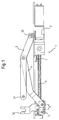
- Fig. 1 is a device 1 for opening and / or Closing a wing relative to a frame stick shown.
- Drive element shown a spindle nut 5 on one by a arranged in a housing 3 and not Spindle motor driven spindle 6 shown in more detail running.
- spindle Limit switches 7, 8 are provided for controlling the motor serve.
- the result is a translationally movable Mechanism that is sufficient with polygonal frame shapes long sides of the windows, doors, skylights to be moved or the like is advantageous.
- this form is pure exemplary, because they are also rotatable drives conceivable, and instead of the spindle drive shown can also belt, chain, linear drives and the like are used.
- a scissor mechanism is shown as the output element.
- a first scissor arm 2 at one end 2R Frame stick (not shown; in Fig. 1 below) e.g. fixed rotatably via a motor housing 3 and on the other End 2F at least rotatable with the wing (also not shown; in Fig. 1 above) connected.
- a second Scissor arm which is designed as an output lever 4, is on one end with the first scissor arm 2 between its ends rotatably and fixedly connected and at its other end a drive element 5 attached.
- There is one Y-scissors which is, however, purely exemplary, since e.g.
- Scissor arm 2 and output lever 4 can also extend beyond the illustrated ends, e.g. around there by means of their continuation and movement to operate according to sash and / or frame stick.
- Fig. 1 shows the device in a position in which the Wing is closed relative to the frame stick.
- the output lever 4 on the drive element 5 rotatable and substantially relative to the drive element Slidably mounted parallel to the spindle axis. This enables a defined during the opening process Idle stroke 9.
- a is on the drive element 5
- the spindle nut 5 moves along the spindle 6.
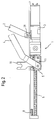
- the idle stroke 9 is first overcome without the wing opens. During this idle stroke the moves Driver 10 with the spindle nut 5 and unlocks the Connection between sash and frame stick. If the idle stroke is 9 overcome, the work stroke begins and with it the Opening process of the wing. At this point the Output lever 4 to the left in the drawing of the Drive elements 5 moves and a stop 11 engages (Fig. 2 and Fig. 4) to the output lever 4 relative to Determine spindle nut 5. With further movement of the Spindle nut 5 on the spindle 6 brings the wing via the output lever 4 and the scissor arm 2 in the open position. The wing can partially, however can also be opened completely.
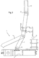
- the wing can float freely over the first Scissor arm 2 or, as shown in Fig. 3, additionally connected to the frame stick via its own joint 12 his. If the sash is articulated to the frame stick, depending on the dimensions and arrangement, this is the first scissor arm 2 typically at its end 2F both rotatable and in Slidable essentially parallel to one side of the wing connected to the wing.
- the first scissor arm 2 in a guide 13 which is integrated in the wing, longitudinally displaceable (Fig. 3).
Landscapes
- Power-Operated Mechanisms For Wings (AREA)
Abstract
Description
- Fig. 1
- eine Draufsicht einer Ausführungsform der erfindungsgemäßen Vorrichtung darstellt, wobei ein Flügel relativ zu einem Rahmenstock geschlossen ist;
- Fig. 2
- eine Draufsicht der erfindungsgemäßen Vorrichtung darstellt, wobei der Flügel relativ zu dem Rahmenstock geöffnet ist;
- Fig. 3
- eine Draufsicht eines Teils der erfindungsgemäßen Vorrichtung ist;
- Fig. 4
- eine Draufsicht der Verbindung des Antriebselements des mit dem Abtriebselement der erfindungsgemäßen Vorrichtung in verriegeltem Zustand darstellt;
- Fig. 5
- eine Draufsicht der Verbindung des Antriebselementes mit dem Abtriebselement der erfindungsgemäßen Vorrichtung in entriegeltem Zustand und ausgeführtem Leerhub darstellt;
- Fig. 6
- einen Schnitt durch die Verbindung des Antriebselements mit dem Abtriebselement bei teilweise ausgerücktem Riegel darstellt; und
- Fig. 7
- eine Draufsicht der erfindungsgemäßen Vorrichtung ist, bei der zur besseren Übersicht das Antriebselement ausgelassen ist.
Claims (15)
- Vorrichtung zum Öffnen und/oder Schließen eines Flügels relativ zu einem Rahmenstock, insbesondere für Drehund/oder Kippfenster, umfassend:dadurch gekennzeichnet, dassein bewegliches Antriebselement (5) zum Erzeugen einer Antriebsbewegung,ein zum Bewegen des Flügels derart mit dem Antriebselement (5) verbundenes Abtriebselement (4, 2), dass das Antriebselement sich relativ zum Abtriebselement bewegend einen Leerhub (9) und sich zusammen mit dem Abtriebselement bewegend einen Arbeitshub ausführt,
die Verbindung zwischen Antriebselement und Abtriebselement eine Verriegelung (11, 14, 15, 16) umfasst, um das Antriebselement (5) an einem Ende seines Leerhubs (9) lösbar an dem Abtriebselement (4) festzustellen. - Vorrichtung nach Anspruch 1, dadurch gekennzeichnet, dass die Verriegelung einen winklig zur Bewegungsrichtung des Antriebselements ausrückbaren Riegel (11) aufweist.
- Vorrichtung nach Anspruch 2, dadurch gekennzeichnet, dass die Verriegelung ferner eine Rampe (14) oder einen Kurvenmechanismus aufweist, die oder der derart in der Vorrichtung angebracht ist, dass eine Relativbewegung von Riegel (11) und Rampe (14) oder Kurvenmechanismus den Riegel zwischen eingerückter und ausgerückter Stellung bewegt.
- Vorrichtung nach Anspruch 3, dadurch gekennzeichnet, dass die Rampe (14) eine Steigung im Bereich von 10°-50°, vorzugsweise zwischen 20° und 35°, und am meisten bevorzugt 30° aufweist.
- Vorrichtung nach einem der Ansprüche 3 oder 4, dadurch gekennzeichnet, dass der Riegel (11) einen Flansch (15) aufweist, der mit der Rampe (14) in Eingriff bringbar ist.
- Vorrichtung nach mindestens einem der Ansprüche 1 bis 5, dadurch gekennzeichnet, dass die Verriegelung des Antriebselements (5) an dem Abtriebselement (4) formschlüssig ist.
- Vorrichtung nach mindestens einem der Ansprüche 1 bis 6, dadurch gekennzeichnet, dass das Antriebselement eine Spindelmutter (5) umfasst, die durch eine Spindel (6) und einen Spindelmotor (3) angetrieben ist.
- Vorrichtung nach Anspruch 7, dadurch gekennzeichnet, dass die Drehzahl der Spindel (6) im Bereich von 15-60 1/min, vorzugsweise im Bereich 20-45 1/min und am meisten bevorzugt im Bereich von 30-35 1/min liegt und die Steigung der Spindel (6) zwischen 1 und 2 liegt und vorzugsweise 1,5 beträgt.
- Vorrichtung nach mindestens einem der Ansprüche 1 bis 8, dadurch gekennzeichnet, dass die Bewegungsrichtung des Antriebselements (5) im wesentlichen parallel zu einer Seite des geschlossenen Flügels ist, und das Abtriebselement einen Scherenmechanismus (4, 2) aufweist.
- Vorrichtung mindestens einem der Ansprüche 1 bis 9, dadurch gekennzeichnet, dass das Abtriebselement einen Scherenmechanismus aufweist, der einen an dem Rahmenstock bzw. dem Flügel drehbar und ortsfest anbringbaren und an dem Flügel bzw. dem Rahmenstock drehbar anbringbaren ersten Scherenarm (2), und einen zweiten Scherenarm (4) umfasst, der mit dem Antriebselement (5) drehbar verbindbar ist.
- Vorrichtung nach Anspruch 10, dadurch gekennzeichnet, dass der zweite Scherenarm (4) relativ zu dem Antriebselement (5) in einer Richtung im wesentlichen parallel zu der Bewegungsrichtung des Antriebselements (5) verschiebbar angebracht ist.
- Vorrichtung nach Anspruch 10 oder 11, dadurch gekennzeichnet, dass der erste Scherenarm (2) an dem Flügel drehbar und ortsfest anbringbar ist.
- Vorrichtung nach Anspruch 10 oder 11, dadurch gekennzeichnet, dass der erste Scherenarm (2) an dem Flügel drehbar und zusätzlich in einer Richtung im Wesentlichen parallel zu einer Seite des Flügels anbringbar ist.
- Vorrichtung nach mindestens einem der Ansprüche 1 bis 13, dadurch gekennzeichnet, dass zum Verriegeln des Flügels mit dem Rahmenstock an dem Antriebselement (5) zusätzlich ein Mitnehmer (10) angebracht ist.
- Fenster mit einer Vorrichtung nach mindestens einem der vorherigen Ansprüche.
Applications Claiming Priority (2)
| Application Number | Priority Date | Filing Date | Title |
|---|---|---|---|
| DE10237492 | 2002-08-16 | ||
| DE10237492A DE10237492B3 (de) | 2002-08-16 | 2002-08-16 | Vorrichtung zum Öffnen und/oder Schließen eines Flügels relativ zu einem Rahmenstock |
Publications (2)
| Publication Number | Publication Date |
|---|---|
| EP1389662A2 true EP1389662A2 (de) | 2004-02-18 |
| EP1389662A3 EP1389662A3 (de) | 2010-03-10 |
Family
ID=29762132
Family Applications (1)
| Application Number | Title | Priority Date | Filing Date |
|---|---|---|---|
| EP03014411A Withdrawn EP1389662A3 (de) | 2002-08-16 | 2003-06-27 | Vorrichtung zum Öffnen und/oder Schliessen eines Flügels relativ zu einem Rahmenstock |
Country Status (2)
| Country | Link |
|---|---|
| EP (1) | EP1389662A3 (de) |
| DE (1) | DE10237492B3 (de) |
Cited By (4)
| Publication number | Priority date | Publication date | Assignee | Title |
|---|---|---|---|---|
| DE202011109760U1 (de) | 2011-05-13 | 2012-03-27 | Gröninger Antriebstechnik GmbH & Co. KG | Antrieb zum Bewegen eines Flügels, eines Fensters oder einer Tür |
| DE202016007175U1 (de) | 2016-11-23 | 2018-02-27 | Siegenia-Aubi Kg | Vorrichtung zum Öffnen und Schließen eines Flügels |
| DE202016007177U1 (de) | 2016-11-23 | 2018-02-28 | Siegenia-Aubi Kg | Vorrichtung zum Öffnen und/oder Schließen eines Flügels |
| EP3540159A1 (de) * | 2018-03-16 | 2019-09-18 | eds - electric drive solution GmbH & Co. KG | Dreh-kipp-fenster |
Families Citing this family (4)
| Publication number | Priority date | Publication date | Assignee | Title |
|---|---|---|---|---|
| DE102004015147A1 (de) * | 2004-03-27 | 2005-10-13 | Aug. Winkhaus Gmbh & Co. Kg | Antriebseinrichtung |
| DE102012203593B4 (de) | 2012-03-07 | 2013-10-31 | Brose Fahrzeugteile Gmbh & Co. Kommanditgesellschaft, Coburg | Fenster oder Tür eines Gebäudes |
| DE102012203602A1 (de) | 2012-03-07 | 2013-09-12 | Brose Fahrzeugteile Gmbh & Co. Kommanditgesellschaft, Coburg | Baugruppe eines Fensters oder einer Tür für ein Gebäude |
| DE102012214003A1 (de) | 2012-08-07 | 2014-02-13 | Brose Fahrzeugteile Gmbh & Co. Kg, Coburg | Schließvorrichtung für eine Gebäudeöffnung |
Family Cites Families (4)
| Publication number | Priority date | Publication date | Assignee | Title |
|---|---|---|---|---|
| US2256613A (en) * | 1939-04-29 | 1941-09-23 | Nat Pneumatic Co | Door operating mechanism |
| DE4219316C2 (de) * | 1992-06-12 | 2002-07-18 | Hautau Gmbh W | Elektromotorisch angetriebener Beschlag |
| DE10148793A1 (de) * | 2000-10-12 | 2002-08-08 | Toni Huber | Einrichtung zum Verschliessen oder Freigeben einer Öffnung |
| DE10143133A1 (de) * | 2001-09-03 | 2003-03-20 | Heinrich Schlueter | Zwangsbewegte Kippscheere für ein Kipp- oder Drehkippfenster |
-
2002
- 2002-08-16 DE DE10237492A patent/DE10237492B3/de not_active Expired - Fee Related
-
2003
- 2003-06-27 EP EP03014411A patent/EP1389662A3/de not_active Withdrawn
Cited By (5)
| Publication number | Priority date | Publication date | Assignee | Title |
|---|---|---|---|---|
| DE202011109760U1 (de) | 2011-05-13 | 2012-03-27 | Gröninger Antriebstechnik GmbH & Co. KG | Antrieb zum Bewegen eines Flügels, eines Fensters oder einer Tür |
| DE202016007175U1 (de) | 2016-11-23 | 2018-02-27 | Siegenia-Aubi Kg | Vorrichtung zum Öffnen und Schließen eines Flügels |
| DE202016007177U1 (de) | 2016-11-23 | 2018-02-28 | Siegenia-Aubi Kg | Vorrichtung zum Öffnen und/oder Schließen eines Flügels |
| EP3540159A1 (de) * | 2018-03-16 | 2019-09-18 | eds - electric drive solution GmbH & Co. KG | Dreh-kipp-fenster |
| EP3540159B1 (de) | 2018-03-16 | 2021-11-10 | eds - electric drive solution GmbH & Co. KG | Dreh-kipp-fenster |
Also Published As
| Publication number | Publication date |
|---|---|
| EP1389662A3 (de) | 2010-03-10 |
| DE10237492B3 (de) | 2004-01-22 |
Similar Documents
| Publication | Publication Date | Title |
|---|---|---|
| EP1991436B1 (de) | Verstellvorrichtung für einen schiebedachdeckel an einem fahrzeug | |
| EP1312742A2 (de) | Austellvorrichtung für einen Kipp-Flügel, insbesondere Dreh-Kipp-Flügel eines Fensters, einer Tür oder dergleichen, entsprechende Fenstereinrichtung und entsprechendes Verfahren zum motorischen und manuellen Kippen | |
| EP3623561A1 (de) | Antriebsschlitten für ein tor sowie torantrieb | |
| DE60318568T2 (de) | Elektrischer Stellantrieb für Schwenktüren und dgl. | |
| EP1072456B1 (de) | Zuzieh- und Verriegelungsvorrichtung zum lösbaren Verbinden eines Fahrzeugdaches mit einem Karosseriebauteil | |
| DE3400753A1 (de) | Aussenschwingtuer fuer fahrzeuge und ihre betaetigungsvorrichtung | |
| EP1947274B1 (de) | Antriebseinrichtung für einen Treibstangenbeschlag | |
| EP1022421B1 (de) | Ausstellvorrichtung für einen an einem Rahmen schwenkbar angebrachten Kipp- oder Dreh-Kipp-Flügel | |
| DE10237492B3 (de) | Vorrichtung zum Öffnen und/oder Schließen eines Flügels relativ zu einem Rahmenstock | |
| DE19718091A1 (de) | Vorrichtung zum Öffnen/Schließen eines Fahrzeugfensters | |
| EP0716004A1 (de) | Schwenkschiebetür für Fahrzeuge zur Personenbeförderung | |
| DE10105771B4 (de) | Verschlußvorrichtung für ein Cabriolet-Verdeck | |
| DE10300882B4 (de) | Verdeckverschluss eines Fahrzeugs | |
| EP2143859B1 (de) | Verriegelungsvorrichtung | |
| DE19958746A1 (de) | Schwenktür für ein Fahrzeug | |
| EP3327235B1 (de) | Vorrichtung zum öffnen und/oder schliessen eines flügels | |
| EP4174265B1 (de) | Flügelanordnung | |
| DE102004044416A1 (de) | Vorrichtung zum Steuern der Bewegungen eines Fenster- oder Türflügels | |
| EP1288418B1 (de) | Beschlagseinheit für ein Kipp- oder Drehkippfenster | |
| EP1170445A2 (de) | Ausstellvorrichtung für einen an einem Rahmen schwenkbar angebrachten Kipp- oder Dreh-Kipp-Flügel | |
| DE10300653A1 (de) | Fenster oder Tür mit Antriebsvorrichtung | |
| EP1990492A2 (de) | Motorschloss mit Mehrpunktverriegelung | |
| DE60032698T2 (de) | Vorrichtung zum Öffnen und Schliessen von Aufzugstürflügeln | |
| DE2345995A1 (de) | Starres schiebedach, insbesondere fuer kraftfahrzeuge | |
| EP1493890B1 (de) | Antrieb für einen Flügel eines Fensters oder einer Klappe |
Legal Events
| Date | Code | Title | Description |
|---|---|---|---|
| PUAI | Public reference made under article 153(3) epc to a published international application that has entered the european phase |
Free format text: ORIGINAL CODE: 0009012 |
|
| AK | Designated contracting states |
Kind code of ref document: A2 Designated state(s): AT BE BG CH CY CZ DE DK EE ES FI FR GB GR HU IE IT LI LU MC NL PT RO SE SI SK TR |
|
| AX | Request for extension of the european patent |
Extension state: AL LT LV MK |
|
| PUAL | Search report despatched |
Free format text: ORIGINAL CODE: 0009013 |
|
| AK | Designated contracting states |
Kind code of ref document: A3 Designated state(s): AT BE BG CH CY CZ DE DK EE ES FI FR GB GR HU IE IT LI LU MC NL PT RO SE SI SK TR |
|
| AX | Request for extension of the european patent |
Extension state: AL LT LV MK |
|
| 17P | Request for examination filed |
Effective date: 20100909 |
|
| AKX | Designation fees paid |
Designated state(s): AT BE BG CH CY CZ DE DK EE ES FI FR GB GR HU IE IT LI LU MC NL PT RO SE SI SK TR |
|
| 17Q | First examination report despatched |
Effective date: 20110614 |
|
| STAA | Information on the status of an ep patent application or granted ep patent |
Free format text: STATUS: THE APPLICATION IS DEEMED TO BE WITHDRAWN |
|
| 18D | Application deemed to be withdrawn |
Effective date: 20111228 |