EP1389662A2 - Opening and/or closing device of a wing with respect to a frame - Google Patents
Opening and/or closing device of a wing with respect to a frame Download PDFInfo
- Publication number
- EP1389662A2 EP1389662A2 EP03014411A EP03014411A EP1389662A2 EP 1389662 A2 EP1389662 A2 EP 1389662A2 EP 03014411 A EP03014411 A EP 03014411A EP 03014411 A EP03014411 A EP 03014411A EP 1389662 A2 EP1389662 A2 EP 1389662A2
- Authority
- EP
- European Patent Office
- Prior art keywords
- drive element
- wing
- drive
- frame
- spindle
- Prior art date
- Legal status (The legal status is an assumption and is not a legal conclusion. Google has not performed a legal analysis and makes no representation as to the accuracy of the status listed.)
- Withdrawn
Links
Images


Classifications
-
- E—FIXED CONSTRUCTIONS
- E05—LOCKS; KEYS; WINDOW OR DOOR FITTINGS; SAFES
- E05F—DEVICES FOR MOVING WINGS INTO OPEN OR CLOSED POSITION; CHECKS FOR WINGS; WING FITTINGS NOT OTHERWISE PROVIDED FOR, CONCERNED WITH THE FUNCTIONING OF THE WING
- E05F15/00—Power-operated mechanisms for wings
- E05F15/60—Power-operated mechanisms for wings using electrical actuators
- E05F15/603—Power-operated mechanisms for wings using electrical actuators using rotary electromotors
- E05F15/611—Power-operated mechanisms for wings using electrical actuators using rotary electromotors for swinging wings
- E05F15/63—Power-operated mechanisms for wings using electrical actuators using rotary electromotors for swinging wings operated by swinging arms
-
- E—FIXED CONSTRUCTIONS
- E05—LOCKS; KEYS; WINDOW OR DOOR FITTINGS; SAFES
- E05F—DEVICES FOR MOVING WINGS INTO OPEN OR CLOSED POSITION; CHECKS FOR WINGS; WING FITTINGS NOT OTHERWISE PROVIDED FOR, CONCERNED WITH THE FUNCTIONING OF THE WING
- E05F15/00—Power-operated mechanisms for wings
- E05F15/60—Power-operated mechanisms for wings using electrical actuators
- E05F15/603—Power-operated mechanisms for wings using electrical actuators using rotary electromotors
- E05F15/611—Power-operated mechanisms for wings using electrical actuators using rotary electromotors for swinging wings
- E05F15/616—Power-operated mechanisms for wings using electrical actuators using rotary electromotors for swinging wings operated by push-pull mechanisms
- E05F15/622—Power-operated mechanisms for wings using electrical actuators using rotary electromotors for swinging wings operated by push-pull mechanisms using screw-and-nut mechanisms
-
- E—FIXED CONSTRUCTIONS
- E05—LOCKS; KEYS; WINDOW OR DOOR FITTINGS; SAFES
- E05F—DEVICES FOR MOVING WINGS INTO OPEN OR CLOSED POSITION; CHECKS FOR WINGS; WING FITTINGS NOT OTHERWISE PROVIDED FOR, CONCERNED WITH THE FUNCTIONING OF THE WING
- E05F15/00—Power-operated mechanisms for wings
- E05F15/60—Power-operated mechanisms for wings using electrical actuators
- E05F15/603—Power-operated mechanisms for wings using electrical actuators using rotary electromotors
-
- E—FIXED CONSTRUCTIONS
- E05—LOCKS; KEYS; WINDOW OR DOOR FITTINGS; SAFES
- E05Y—INDEXING SCHEME RELATING TO HINGES OR OTHER SUSPENSION DEVICES FOR DOORS, WINDOWS OR WINGS AND DEVICES FOR MOVING WINGS INTO OPEN OR CLOSED POSITION, CHECKS FOR WINGS AND WING FITTINGS NOT OTHERWISE PROVIDED FOR, CONCERNED WITH THE FUNCTIONING OF THE WING
- E05Y2201/00—Constructional elements; Accessories therefore
- E05Y2201/20—Brakes; Disengaging means, e.g. clutches; Holders, e.g. locks; Stops; Accessories therefore
- E05Y2201/218—Holders
- E05Y2201/22—Locks
-
- E—FIXED CONSTRUCTIONS
- E05—LOCKS; KEYS; WINDOW OR DOOR FITTINGS; SAFES
- E05Y—INDEXING SCHEME RELATING TO HINGES OR OTHER SUSPENSION DEVICES FOR DOORS, WINDOWS OR WINGS AND DEVICES FOR MOVING WINGS INTO OPEN OR CLOSED POSITION, CHECKS FOR WINGS AND WING FITTINGS NOT OTHERWISE PROVIDED FOR, CONCERNED WITH THE FUNCTIONING OF THE WING
- E05Y2201/00—Constructional elements; Accessories therefore
- E05Y2201/20—Brakes; Disengaging means, e.g. clutches; Holders, e.g. locks; Stops; Accessories therefore
- E05Y2201/23—Actuation thereof
- E05Y2201/232—Actuation thereof by automatically acting means
- E05Y2201/24—Actuation thereof by automatically acting means using lost motion
-
- E—FIXED CONSTRUCTIONS
- E05—LOCKS; KEYS; WINDOW OR DOOR FITTINGS; SAFES
- E05Y—INDEXING SCHEME RELATING TO HINGES OR OTHER SUSPENSION DEVICES FOR DOORS, WINDOWS OR WINGS AND DEVICES FOR MOVING WINGS INTO OPEN OR CLOSED POSITION, CHECKS FOR WINGS AND WING FITTINGS NOT OTHERWISE PROVIDED FOR, CONCERNED WITH THE FUNCTIONING OF THE WING
- E05Y2201/00—Constructional elements; Accessories therefore
- E05Y2201/40—Motors; Magnets; Springs; Weights; Accessories therefore
- E05Y2201/43—Motors
- E05Y2201/434—Electromotors; Details thereof
-
- E—FIXED CONSTRUCTIONS
- E05—LOCKS; KEYS; WINDOW OR DOOR FITTINGS; SAFES
- E05Y—INDEXING SCHEME RELATING TO HINGES OR OTHER SUSPENSION DEVICES FOR DOORS, WINDOWS OR WINGS AND DEVICES FOR MOVING WINGS INTO OPEN OR CLOSED POSITION, CHECKS FOR WINGS AND WING FITTINGS NOT OTHERWISE PROVIDED FOR, CONCERNED WITH THE FUNCTIONING OF THE WING
- E05Y2900/00—Application of doors, windows, wings or fittings thereof
- E05Y2900/10—Application of doors, windows, wings or fittings thereof for buildings or parts thereof
- E05Y2900/13—Application of doors, windows, wings or fittings thereof for buildings or parts thereof characterised by the type of wing
- E05Y2900/148—Windows
Definitions
- the invention relates to a device for opening and / or Closing a wing according to the preamble of claim 1.
- a device for opening and / or Closing a wing according to the preamble of claim 1.
- Such a device also comes in doors and the like for use where opening and closing, for example for ventilation purposes, just closing, for example for usually open fire doors, or just opening is desired, e.g. for usually closed escape doors.
- the spindle drive includes a spindle motor as a drive for a spindle and a Spindle nut.
- the patent DE 42 19 316 C2 shows a device for Opening and / or closing a casement relative to a frame stick, which is a movable drive element for Generate a drive movement, as well as one for moving the Casement connected to the drive element in this way
- Output element includes that the drive element itself an idle stroke and moves relative to the output element moving a working stroke together with the output element performs.
- the patent particularly shows one electromotive fitting for a wing of windows or doors, which is also a spindle-spindle nut drive operated to issue the wing.
- an actuator with the spindle nut over one defined idle path coupled. For this is on Spindle nut attached to a spigot, which in one Angular slot of the actuator moves.
- the actuator is rotatable, however fixed to a frame stick.
- the pin moves the pin along the idle path one side of the angle slot until it reaches the angle of the Angle slot reached. At this point the Raising motion.
- the patent states that the A sash can be used with a sash To finally lock or frame frame stick via locking pin Unlock.
- the invention is based on the object, a reliable working, with less manufacturing effort producible device for opening and / or closing a Propose wing relative to a frame stick.
- connection between the drive element comprises and output element a lock that enables the Drive element at one end of its idle stroke releasably on the Determine output element. It is thus both about almost the entire range of movement of the wing Relative movement between output element and drive element reduced, as well as a flapping of the wing in part or fully opened position minimized. Still is with the wing essentially closed over the idle stroke motor locking possible.
- the lock is angled, preferably at right angles to Movable direction of the drive element releasable bolt on.
- This angular arrangement enables a quick and in Movement range of the drive element can be precisely localized Locking of the input and output element. It also enables it training with a latch, the latch form-fitting and both in and against the Realize the direction of movement of the drive element.
- the bolt has a flange that with the ramp can be engaged.
- the Flange with the ramp by a relative movement of the latch and ramp engages and moves the latch between indented and disengaged position.
- the slope of the ramp is preferably in a range from 10 ° to 50 °, preferably between 20 ° and 35 ° and am most preferably at 30 ° to speed up the or disengagement and the movement conditions of idle stroke too To influence the working stroke in such a way that rapid actuation the device is guaranteed.
- this comprises Drive element a spindle nut, through a spindle and a spindle motor is driven.
- the Spindle speed in a range from 15 to 60 1 / min, preferably in the range of 20 to 45 rpm and most preferably in the range 30 to 35 1 / min, and / or the slope the spindle between 1 and 2 and preferably at 1.5.
- This Conditions enable operation with reasonable Power consumption and an opening and / or closing of heavy wings.
- the direction of movement of the Drive elements substantially parallel to one side of the closed wing and the drive element Scissor mechanism.
- it is Direction of movement of the drive element essentially parallel to one side of the frame stick when it is on the Frame stick is mounted, or essentially parallel to one side of the wing when it is mounted on the wing is.
- the drive element can optionally be equipped with a motor and associated energy supply invisible in the Frame stick can be accommodated.
- the scissor mechanism preferably comprises a first one Scissor arm that is relative to the frame stick or the wing rotatable, stationary and on the wing or Frame stick is attachable and a second scissor arm, the is rotatably connected to the drive element. So it can the scissor mechanism described above an output lever comprise, which is rotatably connected to the drive element and transfers the working stroke to a scissor arm. The The scissor arm can then be relative to the frame stick or the wing rotatable but stationary, and on the other hand the wing or the frame stick.
- the second scissor arm is advantageously relative to that Drive element in a direction substantially parallel to the direction of movement of the drive element displaceable appropriate. This displaceability enables linear Movable drives the idle stroke when the output element is not found on the drive element.
- the first Scissor arm rotatably attached to the wing.
- the wing can thus only via the device according to the invention, or additionally via its own joint with the frame stick be connected.
- the first scissor arm is preferably also in one Direction substantially parallel to one side of the wing stored. Such storage can be used if the sash itself is articulated to the frame stick is.
- a driver can also be attached to the drive element be attached to lock the wing with the Frame stick serves. This enables one and the same drive during the empty stroke also for the Locking the sash on the frame stick is used for example by the driver in pins or the like on a pushrod of a window casement intervenes.
- a window with one of the opening devices described above and / or closing the window is proposed. It can the window is a rotating, tilting or hinged window act. There is also the possibility of the device to use with a skylight or door.
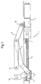
- Fig. 1 is a device 1 for opening and / or Closing a wing relative to a frame stick shown.
- Drive element shown a spindle nut 5 on one by a arranged in a housing 3 and not Spindle motor driven spindle 6 shown in more detail running.
- spindle Limit switches 7, 8 are provided for controlling the motor serve.
- the result is a translationally movable Mechanism that is sufficient with polygonal frame shapes long sides of the windows, doors, skylights to be moved or the like is advantageous.
- this form is pure exemplary, because they are also rotatable drives conceivable, and instead of the spindle drive shown can also belt, chain, linear drives and the like are used.
- a scissor mechanism is shown as the output element.
- a first scissor arm 2 at one end 2R Frame stick (not shown; in Fig. 1 below) e.g. fixed rotatably via a motor housing 3 and on the other End 2F at least rotatable with the wing (also not shown; in Fig. 1 above) connected.
- a second Scissor arm which is designed as an output lever 4, is on one end with the first scissor arm 2 between its ends rotatably and fixedly connected and at its other end a drive element 5 attached.
- There is one Y-scissors which is, however, purely exemplary, since e.g.
- Scissor arm 2 and output lever 4 can also extend beyond the illustrated ends, e.g. around there by means of their continuation and movement to operate according to sash and / or frame stick.
- Fig. 1 shows the device in a position in which the Wing is closed relative to the frame stick.
- the output lever 4 on the drive element 5 rotatable and substantially relative to the drive element Slidably mounted parallel to the spindle axis. This enables a defined during the opening process Idle stroke 9.
- a is on the drive element 5
- the spindle nut 5 moves along the spindle 6.
- the idle stroke 9 is first overcome without the wing opens. During this idle stroke the moves Driver 10 with the spindle nut 5 and unlocks the Connection between sash and frame stick. If the idle stroke is 9 overcome, the work stroke begins and with it the Opening process of the wing. At this point the Output lever 4 to the left in the drawing of the Drive elements 5 moves and a stop 11 engages (Fig. 2 and Fig. 4) to the output lever 4 relative to Determine spindle nut 5. With further movement of the Spindle nut 5 on the spindle 6 brings the wing via the output lever 4 and the scissor arm 2 in the open position. The wing can partially, however can also be opened completely.
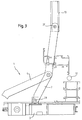
- the wing can float freely over the first Scissor arm 2 or, as shown in Fig. 3, additionally connected to the frame stick via its own joint 12 his. If the sash is articulated to the frame stick, depending on the dimensions and arrangement, this is the first scissor arm 2 typically at its end 2F both rotatable and in Slidable essentially parallel to one side of the wing connected to the wing.
- the first scissor arm 2 in a guide 13 which is integrated in the wing, longitudinally displaceable (Fig. 3).
Abstract
Description
Die Erfindung betrifft eine Vorrichtung zum Öffnen und/oder
Schließen eines Flügels nach dem Oberbegriff des Anspruchs 1.
Eine derartige Vorrichtung kommt auch in Türen und
dergleichen zur Anwendung, wo ein Öffnen und Schließen,
beispielsweise zu Lüftungszwecken, nur das Schließen,
beispielsweise für i.d.R. offen stehende Feuertüren, oder nur
das Öffnen gewünscht ist, beispielsweise für i.d.R.
geschlossene Fluchttüren.The invention relates to a device for opening and / or
Closing a wing according to the preamble of
Aus US 2256613 ist eine Vorrichtung zum Öffnen einer Tür offenbart, die die Tür mittels eines scherenartigen Gestänges und eines Spindeltriebs öffnet. Der Spindeltrieb umfasst einen Spindelmotor als Antrieb für eine Spindel und eine Spindelmutter.From US 2256613 is a device for opening a door discloses the door by means of a scissor-like linkage and a spindle drive opens. The spindle drive includes a spindle motor as a drive for a spindle and a Spindle nut.
Ferner zeigt das Patent DE 42 19 316 C2 eine Vorrichtung zum Öffnen und/oder Schließen eines Flügelrahmens relativ zu einem Rahmenstock, die ein bewegliches Antriebselement zum Erzeugen einer Antriebsbewegung, sowie ein zum Bewegen des Flügelrahmens derart mit dem Antriebselement verbundenes Abtriebselement umfasst, dass das Antriebselement sich relativ zum Abtriebselement bewegend einen Leerhub und sich zusammen mit dem Abtriebselement bewegend einen Arbeitshub ausführt. Das Patent zeigt insbesondere einen elektromotorischen Beschlag für einen Flügel von Fenstern oder Türen, der sich ebenfalls eines Spindel-Spindelmutter-Antriebs zum Ausstellen des Flügels bedient. Zusätzlich ist ein Ausstellglied mit der Spindelmutter über einen definierten Leerweg gekoppelt. Hierfür ist an der Spindelmutter ein Zapfen angebracht, der in einem Winkelschlitz des Ausstellgliedes verfährt. Entfernt vom Winkelschlitz ist das Ausstellglied drehbeweglich aber ortsfest an einem Rahmenstock angebracht. Bei Verfahren der Spindelmutter bewegt sich der Zapfen über den Leerweg entlang einer Seite des Winkelschlitzes bis er den Winkel des Winkelschlitzes erreicht. Zu diesem Zeitpunkt beginnt die Ausstellbewegung. In dem Patent ist angegeben, dass der Leerweg dazu dienen kann, einen Flügelrahmen mit einem Rahmenstock über Riegelzapfen endgültig zu ver- oder entriegeln.Furthermore, the patent DE 42 19 316 C2 shows a device for Opening and / or closing a casement relative to a frame stick, which is a movable drive element for Generate a drive movement, as well as one for moving the Casement connected to the drive element in this way Output element includes that the drive element itself an idle stroke and moves relative to the output element moving a working stroke together with the output element performs. The patent particularly shows one electromotive fitting for a wing of windows or doors, which is also a spindle-spindle nut drive operated to issue the wing. In addition is an actuator with the spindle nut over one defined idle path coupled. For this is on Spindle nut attached to a spigot, which in one Angular slot of the actuator moves. Removed from Angular slot, the actuator is rotatable, however fixed to a frame stick. In the process of Spindle nut moves the pin along the idle path one side of the angle slot until it reaches the angle of the Angle slot reached. At this point the Raising motion. The patent states that the A sash can be used with a sash To finally lock or frame frame stick via locking pin Unlock.
Bei derartigen relativ zu einem Rahmenstock kipp- und/oder drehbaren Flügelrahmen kann es durch eine auf den ganz oder teilweise geöffneten Flügel aufgebrachte Last dazu kommen, dass der Flügel schlägt, entsprechende Geräusche verursacht und sogar zerstört wird. Um ein solches Schlagen zu verhindern, müssen bei der bekannten Ausführungsform der Zapfen, der Winkelschlitz, das Ausstellglied sowie Flügelrahmen und Rahmenstock inklusive ihrer Montagestellen entsprechend eng toleriert werden. Folglich müssen diese Teile extrem hohen Fertigungsqualitäten mit extrem niedrigen Fertigungstoleranzen genügen. Dies ergibt einen unerwünscht hohen Aufwand.In such a tilt and / or relative to a frame stick swiveling casement can be made on the whole or by a partially opened sash applied load that the wing beats, makes corresponding noises and is even destroyed. To hit like that must prevent in the known embodiment of the Pin, the angled slot, the actuator as well Sash frame and frame frame including their assembly points be narrowly tolerated accordingly. Hence, these must Parts of extremely high manufacturing quality with extremely low Manufacturing tolerances are sufficient. This makes one undesirable high effort.
Der Erfindung liegt demgegenüber die Aufgabe zugrunde, eine zuverlässig arbeitende, mit geringerem Fertigungsaufwand herstellbare Vorrichtung zum Öffnen und/oder Schließen eines Flügels relativ zu einem Rahmenstock vorzuschlagen.The invention is based on the object, a reliable working, with less manufacturing effort producible device for opening and / or closing a Propose wing relative to a frame stick.
Diese Aufgabe wird durch eine Vorrichtung mit den Merkmalen
von Anspruch 1 gelöst. Vorteilhafte Weiterbildungen sind in
den Unteransprüchen angegeben. This task is accomplished by a device with the features
solved by
Entsprechend umfasst die Verbindung zwischen Antriebselement und Abtriebselement eine Verriegelung, die es ermöglicht, das Antriebselement an einem Ende seines Leerhubs lösbar an dem Abtriebselement festzustellen. Es wird somit sowohl über nahezu den gesamten Bewegungsbereich des Flügels eine Relativbewegung zwischen Abtriebselement und Antriebselement reduziert, als auch ein Schlagen des Flügels in teilweise oder vollständig geöffneter Stellung minimiert. Dennoch ist bei im Wesentlichen geschlossenem Flügel über den Leerhub eine motorische Verriegelung möglich.Correspondingly, the connection between the drive element comprises and output element a lock that enables the Drive element at one end of its idle stroke releasably on the Determine output element. It is thus both about almost the entire range of movement of the wing Relative movement between output element and drive element reduced, as well as a flapping of the wing in part or fully opened position minimized. Still is with the wing essentially closed over the idle stroke motor locking possible.
Nach einer bevorzugten Ausführungsform der Erfindung weist die Verriegelung einen winkelig, bevorzugt rechtwinklig zur Bewegungsrichtung des Antriebselements ausrückbaren Riegel auf. Diese winklige Anordnung ermöglicht eine schnelle und im Bewegungsbereich des Antriebselements genau lokalisierbare Verriegelung von An- und Abtriebselement. Überdies ermöglicht es die Ausbildung mit einem Riegel, die Verriegelung formschlüssig und sowohl in als auch gegen die Bewegungsrichtung des Antriebselements zu verwirklichen.According to a preferred embodiment of the invention the lock is angled, preferably at right angles to Movable direction of the drive element releasable bolt on. This angular arrangement enables a quick and in Movement range of the drive element can be precisely localized Locking of the input and output element. It also enables it training with a latch, the latch form-fitting and both in and against the Realize the direction of movement of the drive element.
Um die Anzahl der angetriebenen und mit Energie zu versorgenden Komponenten der erfindungsgemäßen Vorrichtung, und somit den Installierungs-, Wartungs- und Reparaturaufwand niedrig zu halten, ist die Verriegelung einer weiteren vorteilhaften Ausführungsform mit einer Rampe oder einem Kurvenmechanismus versehen, die oder der derart in der Vorrichtung angebracht ist, dass eine Relativbewegung von Riegel und Rampe den Riegel zwischen eingerückter und ausgerückter Stellung bewegt. Es kann also die ohnehin auszuführende Bewegung des Antriebselements genutzt werden, um die Verriegelung von An- und Abtriebselement zu lösen. Bei diesem Mechanismus kann das Antriebselement bei seiner Bewegung relativ zu einer feststehenden Rampe oder einem feststehenden Kurvenmechanismus derart mit dem Riegel in Eingriff kommen, dass dieser aus einer eingerückten, das Abtriebselement an dem Antriebselement feststellende, in eine ausgerückte, den Leerhub zulassende Stellung bewegt wird.To the number of powered and with energy too supplying components of the device according to the invention, and thus the installation, maintenance and repair work keeping it low is another one advantageous embodiment with a ramp or a Provided cam mechanism, or so in the Device is attached that a relative movement of Latch and ramp the latch between indented and moved out of position. So it can anyway movement of the drive element to be carried out are used, to release the locking of the input and output element. at this mechanism, the drive element in his Movement relative to a fixed ramp or a fixed cam mechanism so with the bolt in Intervention that come from an indented that Output element on the drive element, in a disengaged position allowing the idle stroke is moved.
Um einen in ihrer Länge platzsparende Vorrichtung zu verwirklichen, weist der Riegel einen Flansch auf, der mit der Rampe in Eingriff bringbar ist. Vorzugsweise kommt der Flansch mit der Rampe durch eine Relativbewegung von Riegel und Rampe in Eingriff und bewegt den Riegel zwischen eingerückter und ausgerückter Stellung.To make a device that saves space in length realize, the bolt has a flange that with the ramp can be engaged. Preferably comes the Flange with the ramp by a relative movement of the latch and ramp engages and moves the latch between indented and disengaged position.
Die Steigung der Rampe liegt vorzugsweise in einem Bereich von 10° bis 50°, vorzugsweise zwischen 20° und 35° und am meisten bevorzugt bei 30°, um die Geschwindigkeit des Ein- bzw. Ausrückens und die Bewegungsverhältnisse von Leerhub zu Arbeitshub so zu beeinflussen, dass eine zügige Betätigung der Vorrichtung gewährleistet ist.The slope of the ramp is preferably in a range from 10 ° to 50 °, preferably between 20 ° and 35 ° and am most preferably at 30 ° to speed up the or disengagement and the movement conditions of idle stroke too To influence the working stroke in such a way that rapid actuation the device is guaranteed.
Nach einer bevorzugten Ausführungsform umfasst das Antriebselement eine Spindelmutter, die durch eine Spindel und einen Spindelmotor angetrieben ist. Dabei liegt die Spindeldrehzahl in einem Bereich von 15 bis 60 1/min, vorzugsweise im Bereich 20 bis 45 1/min und am meisten bevorzugt im Bereich 30 bis 35 1/min, und/oder die Steigung der Spindel zwischen 1 und 2 und vorzugsweise bei 1,5. Diese Verhältnisse ermöglichen einen Betrieb mit angemessener Leistungsaufnahme und ein Öffnen und/oder Schließen auch von schweren Flügeln.According to a preferred embodiment, this comprises Drive element a spindle nut, through a spindle and a spindle motor is driven. Here lies the Spindle speed in a range from 15 to 60 1 / min, preferably in the range of 20 to 45 rpm and most preferably in the range 30 to 35 1 / min, and / or the slope the spindle between 1 and 2 and preferably at 1.5. This Conditions enable operation with reasonable Power consumption and an opening and / or closing of heavy wings.
Vorteilhafterweise ist die Bewegungsrichtung des Antriebselements im Wesentlichen parallel zu einer Seite des geschlossenen Flügels und das Antriebselement ein Scherenmechanismus. In anderen Worten ist die Bewegungsrichtung des Antriebselements im Wesentlichen parallel zu einer Seite des Rahmenstocks, wenn es an dem Rahmenstock montiert ist, oder aber im Wesentlichen parallel zu einer Seite des Flügels, wenn es an dem Flügel montiert ist. Auf diese Weise kann das Antriebselement ggf. mit Motor und zugehöriger Energieversorgung unsichtbar in dem Rahmenstock untergebracht werden.The direction of movement of the Drive elements substantially parallel to one side of the closed wing and the drive element Scissor mechanism. In other words, it is Direction of movement of the drive element essentially parallel to one side of the frame stick when it is on the Frame stick is mounted, or essentially parallel to one side of the wing when it is mounted on the wing is. In this way, the drive element can optionally be equipped with a motor and associated energy supply invisible in the Frame stick can be accommodated.
Vorzugsweise umfasst der Scherenmechanismus einen ersten Scherenarm, der relativ zu dem Rahmenstock bzw. dem Flügel drehbar, ortsfest angeordnet und an dem Flügel bzw. dem Rahmenstock anbringbar ist und einen zweiten Scherenarm, der mit dem Antriebselement drehbar verbunden ist. Es kann also der zuvor beschriebene Scherenmechanismus einen Abtriebshebel umfassen, der mit dem Antriebselement drehbar verbunden ist und den Arbeitshub auf einen Scherenarm überträgt. Der Scherenarm kann dann einerseits relativ zu dem Rahmenstock bzw. dem Flügel drehbar aber ortsfest, und andererseits an dem Flügel bzw. dem Rahmenstock angebracht sein.The scissor mechanism preferably comprises a first one Scissor arm that is relative to the frame stick or the wing rotatable, stationary and on the wing or Frame stick is attachable and a second scissor arm, the is rotatably connected to the drive element. So it can the scissor mechanism described above an output lever comprise, which is rotatably connected to the drive element and transfers the working stroke to a scissor arm. The The scissor arm can then be relative to the frame stick or the wing rotatable but stationary, and on the other hand the wing or the frame stick.
Vorteilhafterweise ist der zweite Scherenarm relativ zu dem Antriebselement in einer Richtung im Wesentlichen parallel zu der Bewegungsrichtung des Antriebselements verschiebbar angebracht. Diese Verschiebbarkeit ermöglicht bei linear beweglichen Antrieben den Leerhub, wenn das Abtriebselement nicht an dem Antriebselement festgestellt ist.The second scissor arm is advantageously relative to that Drive element in a direction substantially parallel to the direction of movement of the drive element displaceable appropriate. This displaceability enables linear Movable drives the idle stroke when the output element is not found on the drive element.
Nach einer vorteilhaften Ausführungsform ist der erste Scherenarm drehbar an dem Flügel angebracht. Der Flügel kann somit nur über die erfindungsgemäße Vorrichtung, oder zusätzlich über ein eigenes Gelenk mit dem Rahmenstock verbunden sein.According to an advantageous embodiment, the first Scissor arm rotatably attached to the wing. The wing can thus only via the device according to the invention, or additionally via its own joint with the frame stick be connected.
Vorzugsweise ist der erste Scherenarm zusätzlich in einer Richtung im Wesentlichen parallel zu einer Seite des Flügels gelagert. Eine derartige Lagerung kann zum Einsatz kommen, wenn der Flügel selbst gelenkig mit dem Rahmenstock verbunden ist.The first scissor arm is preferably also in one Direction substantially parallel to one side of the wing stored. Such storage can be used if the sash itself is articulated to the frame stick is.
An dem Antriebselement kann zusätzlich ein Mitnehmer angebracht sein, der zum Verriegeln des Flügels mit dem Rahmenstock dient. Hierdurch wird ermöglicht, dass ein und derselbe Antrieb während des Leerhubs auch für die Verriegelung des Flügels an dem Rahmenstock dient, beispielsweise indem der Mitnehmer in Zapfen oder dergleichen auf einer Schieberstange eines Fensterflügelrahmens eingreift.A driver can also be attached to the drive element be attached to lock the wing with the Frame stick serves. This enables one and the same drive during the empty stroke also for the Locking the sash on the frame stick is used for example by the driver in pins or the like on a pushrod of a window casement intervenes.
Nach einem weiteren Aspekt der Erfindung wird ein Fenster mit einer der zuvor beschriebenen Vorrichtungen zum Öffnen und/oder Schließen des Fensters vorgeschlagen. Dabei kann es sich bei dem Fenster um ein Dreh-, Kipp- oder Ausstellfenster handeln. Ferner besteht auch die Möglichkeit, die Vorrichtung mit einem Oberlicht oder einer Tür zu verwenden.According to a further aspect of the invention, a window with one of the opening devices described above and / or closing the window is proposed. It can the window is a rotating, tilting or hinged window act. There is also the possibility of the device to use with a skylight or door.
Ein Ausführungsbeispiel der Erfindung wird nachfolgend anhand der Zeichnung näher erläutert. Es zeigt:
- Fig. 1
- eine Draufsicht einer Ausführungsform der erfindungsgemäßen Vorrichtung darstellt, wobei ein Flügel relativ zu einem Rahmenstock geschlossen ist;
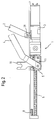
- Fig. 2
- eine Draufsicht der erfindungsgemäßen Vorrichtung darstellt, wobei der Flügel relativ zu dem Rahmenstock geöffnet ist;
- Fig. 3
- eine Draufsicht eines Teils der erfindungsgemäßen Vorrichtung ist;
- Fig. 4
- eine Draufsicht der Verbindung des Antriebselements des mit dem Abtriebselement der erfindungsgemäßen Vorrichtung in verriegeltem Zustand darstellt;
- Fig. 5
- eine Draufsicht der Verbindung des Antriebselementes mit dem Abtriebselement der erfindungsgemäßen Vorrichtung in entriegeltem Zustand und ausgeführtem Leerhub darstellt;
- Fig. 6
- einen Schnitt durch die Verbindung des Antriebselements mit dem Abtriebselement bei teilweise ausgerücktem Riegel darstellt; und
- Fig. 7
- eine Draufsicht der erfindungsgemäßen Vorrichtung ist, bei der zur besseren Übersicht das Antriebselement ausgelassen ist.
- Fig. 1
- is a plan view of an embodiment of the device according to the invention, wherein a wing is closed relative to a frame stick;
- Fig. 2
- is a plan view of the device according to the invention, wherein the wing is open relative to the frame stock;
- Fig. 3
- is a plan view of part of the device according to the invention;
- Fig. 4
- a top view of the connection of the drive element of the with the output element of the device according to the invention in the locked state;
- Fig. 5
- a plan view of the connection of the drive element with the output element of the device according to the invention in the unlocked state and executed idle stroke;
- Fig. 6
- a section through the connection of the drive element to the output element with the bolt partially disengaged; and
- Fig. 7
- is a plan view of the device according to the invention, in which the drive element is omitted for a better overview.
In Fig. 1 ist eine Vorrichtung 1 zum Öffnen und/oder
Schließen eines Flügels relativ zu einem Rahmenstock
dargestellt. In dem Ausführungsbeispiel ist als
Antriebselement eine Spindelmutter 5 dargestellt, die auf
einer durch einen in einem Gehäuse 3 angeordneten und nicht
näher dargestellten Spindelmotor angetriebene Spindel 6
läuft. Ferner sind in den beiden Endbereichen der Spindel
Endschalter 7, 8 vorgesehen, die der Steuerung des Motors
dienen. Es ergibt sich ein translatorisch bewegbarer
Mechanismus, der bei polygonalen Rahmenformen mit ausreichend
langen Seiten der zu bewegenden Fenster, Türen, Oberlichter
oder dergleichen vorteilhaft ist. Diese Form ist jedoch rein
beispielhaft, denn es sind auch drehbewegliche Antriebe
denkbar, und anstelle des dargestellten Spindelantriebs
können auch Riemen-, Ketten-, Linearantriebe und dergleichen
zum Einsatz kommen.In Fig. 1 is a
Als Abtriebselement ist ein Scherenmechanismus dargestellt.
Dabei ist ein erster Scherenarm 2 an einem Ende 2R an dem
Rahmenstock (nicht dargestellt; in der Fig. 1 unten) z.B.
über ein Motorengehäuse 3 drehbar fixiert und an dem anderen
Ende 2F zumindest drehbar mit dem Flügel (ebenfalls nicht
dargestellt; in der Fig. 1 oben) verbunden. Ein zweiter
Scherenarm, der als Abtriebshebel 4 ausgeführt ist, ist an
einem Ende mit dem ersten Scherenarm 2 zwischen dessen Enden
drehbar und ortsfest verbunden und an seinem anderen Ende an
einem Antriebselement 5 angebracht. Es ergibt sich eine
Y-Schere, die allerdings rein beispielhaft ist, da z.B. auch
X-Scheren oder andere Ausstellmechanismen wie Winkelhebel
ohne Weiteres denkbar sind. Auch kann die Vorrichtung mit dem
Motorengehäuse 3 an dem Flügel befestigt sein. In diesem Fall
wäre das Ende 2F des Scherenarms 2 an dem Rahmenstock
befestigt. Auch können sich Scherenarm 2 und Abtriebshebel 4
über die dargestellten Enden hinaus erstrecken, z.B. um dort
mittels ihrer Fortsetzung und Bewegung weitere Elemente an
entsprechend Flügel und/oder Rahmenstock zu bedienen.A scissor mechanism is shown as the output element.
There is a
Fig. 1 zeigt die Vorrichtung in einer Stellung, in der der
Flügel relativ zum Rahmenstock geschlossen ist. In dieser
Stellung ist der Abtriebshebel 4 auf dem Antriebselement 5
drehbar und relativ zu dem Antriebselement im Wesentlichen
parallel zu der Spindelachse verschieblich angebracht. Dies
ermöglicht während des Öffnungsvorgangs einen definierten
Leerhub 9. Zusätzlich ist an dem Antriebselement 5 ein
Mitnehmer 10 angebracht, der beispielsweise mit einer
Schieberstange des Flügels in Eingriff kommt, um diesen
relativ zu dem Rahmenstock zu verriegeln.Fig. 1 shows the device in a position in which the
Wing is closed relative to the frame stick. In this
Position is the output lever 4 on the
Um den Flügel von der in Fig. 1 dargestellten, geschlossenen
Stellung in die in Fig. 2 dargestellte, geöffnete Stellung zu
bringen, bewegt sich die Spindelmutter 5 entlang der Spindel
6. Dabei wird zuerst der Leerhub 9 überwunden, ohne dass sich
der Flügel öffnet. Während dieses Leerhubs bewegt sich der
Mitnehmer 10 mit der Spindelmutter 5 und entriegelt so die
Verbindung zwischen Flügel und Rahmenstock. Ist der Leerhub 9
überwunden, beginnt der Arbeitshub und mit ihm der
Öffnungsvorgang des Flügels. Zu diesem Zeitpunkt hat sich der
Abtriebshebel 4 zu dem in der Zeichnung linken Ende des
Antriebselements 5 bewegt und ein Anschlag 11 rückt ein (Fig.
2 und Fig. 4), um den Abtriebshebel 4 relativ zur
Spindelmutter 5 festzustellen. Bei weiterer Bewegung der
Spindelmutter 5 auf der Spindel 6 bringt diese den Flügel
über den Abtriebshebel 4 und den Scherenarm 2 in die
geöffnete Stellung. Dabei kann der Flügel teilweise, aber
auch vollständig geöffnet werden. To the wing of the closed shown in Fig. 1
Position in the open position shown in Fig. 2 to
bring, the
Der Flügel kann dabei freischwebend über den ersten
Scherenarm 2 oder, wie in Fig. 3 dargestellt ist, zusätzlich
über ein eigenes Gelenk 12 mit dem Rahmenstock verbunden
sein. Ist der Flügel gelenkig mit dem Rahmenstock verbunden,
so ist je nach Abmessungen und Anordnung der erste Scherenarm
2 typischerweise an seinem Ende 2F sowohl drehbar als auch im
Wesentlichen parallel zu einer Seite des Flügels verschiebbar
mit dem Flügel verbunden. Dabei wird der erste Scherenarm 2
in einer Führung 13, welche in dem Flügel integriert ist,
längs verschieblich geführt (Fig. 3).The wing can float freely over the
Zum Schließen des Flügels aus beispielsweise einer geöffneten
Stellung, die in Fig. 2 dargestellt ist, wird die
Drehrichtung der Spindel 6 umgekehrt, so dass sich die
Spindelmutter 5 entlang der Spindel 6 in die zur Richtung zum
Öffnen des Flügels entgegengesetzte Richtung bewegt.To close the wing from, for example, an open one
Position, which is shown in Fig. 2, the
Direction of rotation of the
Während der gesamten Öffnungs- bzw. Schließbewegung ist der
Abtriebshebel 4 an der Spindelmutter 5 durch den Riegel 11
festgestellt. Der Riegel 11 ist nämlich über eine Feder 16
vorgespannt, so dass er dann, wenn sich die Spindelmutter
außerhalb des Leerhubs 9 befindet, automatisch eine Stellung
einnimmt, in der er den Abtriebshebel 4 relativ zu dem
Antriebselement 5 sowohl in als auch gegen die
Bewegungsrichtung der Spindelmutter 5 festlegt. Eine
Detailansicht des derart verriegelten Abtriebshebels 4 mit
dem Antriebselement 5 findet sich in Fig. 4.During the entire opening or closing movement, the
Output lever 4 on the
Bei nahezu geschlossenem Flügel jedoch erreicht die
Spindelmutter 5, wie in Fig. 7 dargestellt ist, eine Rampe 14
oder einen Kurvenmechanismus. Zu diesem Zeitpunkt kommt ein
Flansch 15 des Riegels 11 mit der Rampe 14 in Eingriff (Fig.
6). Sobald Flansch 15 und Rampe 14 in Eingriff kommen, wird
durch die Relativbewegung zwischen Flansch 15 und Rampe 14
und durch die Steigung der Rampe 14 die Kraft der Feder 16
überwunden, so dass der Riegel 11 ausrückt. Hierdurch ist
eine Relativbewegung zwischen dem Abtriebshebel 4 und der
Spindelmutter 5 im Wesentlichen parallel zu der Längsachse
der Spindel 6 ermöglicht. Da sich das Fenster zu diesem
Zeitpunkt bereits in einer im Wesentlichen geschlossenen Lage
befindet, ergibt eine weitere Bewegung des Antriebselements 5
auf der Spindel einen Hub ohne Bewegung des Flügels, also
einen Leerhub 9. Während dieses Leerhubs bewegt sich der
Mitnehmer 10, der aufgrund der Schließbewegung des Flügels
mit beispielsweise einer Schieberstange in Eingriff gebracht
werden kann, weiter. Dies kann geeignet genutzt werden, um
den Flügel mit dem Rahmenstock zu verriegeln.With the wing almost closed, however, the
Claims (15)
die Verbindung zwischen Antriebselement und Abtriebselement eine Verriegelung (11, 14, 15, 16) umfasst, um das Antriebselement (5) an einem Ende seines Leerhubs (9) lösbar an dem Abtriebselement (4) festzustellen.Device for opening and / or closing a sash relative to a frame frame, in particular for rotating and / or tilting windows, comprising:
the connection between the drive element and the driven element comprises a lock (11, 14, 15, 16) in order to detachably fix the drive element (5) on the driven element (4) at one end of its empty stroke (9).
Applications Claiming Priority (2)
| Application Number | Priority Date | Filing Date | Title |
|---|---|---|---|
| DE10237492 | 2002-08-16 | ||
| DE2002137492 DE10237492B3 (en) | 2002-08-16 | 2002-08-16 | Device for opening and / or closing a wing relative to a frame stick |
Publications (2)
| Publication Number | Publication Date |
|---|---|
| EP1389662A2 true EP1389662A2 (en) | 2004-02-18 |
| EP1389662A3 EP1389662A3 (en) | 2010-03-10 |
Family
ID=29762132
Family Applications (1)
| Application Number | Title | Priority Date | Filing Date |
|---|---|---|---|
| EP03014411A Withdrawn EP1389662A3 (en) | 2002-08-16 | 2003-06-27 | Opening and/or closing device of a wing with respect to a frame |
Country Status (2)
| Country | Link |
|---|---|
| EP (1) | EP1389662A3 (en) |
| DE (1) | DE10237492B3 (en) |
Cited By (4)
| Publication number | Priority date | Publication date | Assignee | Title |
|---|---|---|---|---|
| DE202011109760U1 (en) | 2011-05-13 | 2012-03-27 | Gröninger Antriebstechnik GmbH & Co. KG | Drive for moving a grand piano, a window or a door |
| DE202016007175U1 (en) | 2016-11-23 | 2018-02-27 | Siegenia-Aubi Kg | Device for opening and closing a wing |
| DE202016007177U1 (en) | 2016-11-23 | 2018-02-28 | Siegenia-Aubi Kg | Device for opening and / or closing a wing |
| EP3540159A1 (en) * | 2018-03-16 | 2019-09-18 | eds - electric drive solution GmbH & Co. KG | Tilt / turn window |
Families Citing this family (4)
| Publication number | Priority date | Publication date | Assignee | Title |
|---|---|---|---|---|
| DE102004015147A1 (en) * | 2004-03-27 | 2005-10-13 | Aug. Winkhaus Gmbh & Co. Kg | driving means |
| DE102012203602A1 (en) | 2012-03-07 | 2013-09-12 | Brose Fahrzeugteile Gmbh & Co. Kommanditgesellschaft, Coburg | Assembly of a window or door for a building |
| DE102012203593B4 (en) | 2012-03-07 | 2013-10-31 | Brose Fahrzeugteile Gmbh & Co. Kommanditgesellschaft, Coburg | Window or door of a building |
| DE102012214003A1 (en) | 2012-08-07 | 2014-02-13 | Brose Fahrzeugteile Gmbh & Co. Kg, Coburg | Closing device for a building opening |
Citations (2)
| Publication number | Priority date | Publication date | Assignee | Title |
|---|---|---|---|---|
| DE10148793A1 (en) * | 2000-10-12 | 2002-08-08 | Toni Huber | Flap opening and closing aperture has control in form of strip, slide elements, counter elements, drive element, locking bolts fitting into slot. |
| EP1288418A2 (en) * | 2001-09-03 | 2003-03-05 | SCHÜCO International KG | Fitting for a tilting or tilting-and-turning window |
Family Cites Families (2)
| Publication number | Priority date | Publication date | Assignee | Title |
|---|---|---|---|---|
| US2256613A (en) * | 1939-04-29 | 1941-09-23 | Nat Pneumatic Co | Door operating mechanism |
| DE4219316C2 (en) * | 1992-06-12 | 2002-07-18 | Hautau Gmbh W | Fitting driven by an electric motor |
-
2002
- 2002-08-16 DE DE2002137492 patent/DE10237492B3/en not_active Expired - Fee Related
-
2003
- 2003-06-27 EP EP03014411A patent/EP1389662A3/en not_active Withdrawn
Patent Citations (2)
| Publication number | Priority date | Publication date | Assignee | Title |
|---|---|---|---|---|
| DE10148793A1 (en) * | 2000-10-12 | 2002-08-08 | Toni Huber | Flap opening and closing aperture has control in form of strip, slide elements, counter elements, drive element, locking bolts fitting into slot. |
| EP1288418A2 (en) * | 2001-09-03 | 2003-03-05 | SCHÜCO International KG | Fitting for a tilting or tilting-and-turning window |
Cited By (5)
| Publication number | Priority date | Publication date | Assignee | Title |
|---|---|---|---|---|
| DE202011109760U1 (en) | 2011-05-13 | 2012-03-27 | Gröninger Antriebstechnik GmbH & Co. KG | Drive for moving a grand piano, a window or a door |
| DE202016007175U1 (en) | 2016-11-23 | 2018-02-27 | Siegenia-Aubi Kg | Device for opening and closing a wing |
| DE202016007177U1 (en) | 2016-11-23 | 2018-02-28 | Siegenia-Aubi Kg | Device for opening and / or closing a wing |
| EP3540159A1 (en) * | 2018-03-16 | 2019-09-18 | eds - electric drive solution GmbH & Co. KG | Tilt / turn window |
| EP3540159B1 (en) | 2018-03-16 | 2021-11-10 | eds - electric drive solution GmbH & Co. KG | Tilt / turn window |
Also Published As
| Publication number | Publication date |
|---|---|
| EP1389662A3 (en) | 2010-03-10 |
| DE10237492B3 (en) | 2004-01-22 |
Similar Documents
| Publication | Publication Date | Title |
|---|---|---|
| EP1991436B1 (en) | Adjustment device for a sliding roof cover on a vehicle | |
| EP1312742A2 (en) | Checking device for a tilting wing, in particular a pivoting-and-tilting wing of a window, door or the like, corresponding window and corresponding method for motor-driven and manual tilting | |
| EP1464529A2 (en) | Fuel tank closure | |
| DE60318568T2 (en) | Electric actuator for swing doors and the like. | |
| EP1072456B1 (en) | Tensioning and locking device for releasibly fixing a vehicle roof to a vehicle body part | |
| DE102015000452A1 (en) | Device for assisting and facilitating the opening and closing of a window or a door | |
| DE10237492B3 (en) | Device for opening and / or closing a wing relative to a frame stick | |
| DE19718091A1 (en) | Opening and closing mechanism for car window with pinion and gear segment | |
| EP0716004A1 (en) | Pivoting and sliding door for passenger-transporting vehicles | |
| EP1947274B1 (en) | Actuation device for a fitting on a connecting rod | |
| EP1022421B1 (en) | Checking device for a tilting or tilting and pivoting wing pivotably mounted to a frame | |
| DE3400753A1 (en) | Outer swing door for vehicles, and its actuating device | |
| DE10105771B4 (en) | Locking device for a convertible top | |
| EP2143859B1 (en) | Locking device | |
| DE10300882B4 (en) | Cover of a vehicle | |
| DE202005021326U1 (en) | Car door | |
| EP1288418B1 (en) | Fitting for a tilting or tilting-and-turning window | |
| EP1170445A2 (en) | Checking device for a tilting or tilting and pivoting wing pivotably mounted to a frame | |
| EP3327235B1 (en) | Device for opening and/or closing a wing | |
| DE19958746A1 (en) | Swinging vehicle door which opens to a position flat against the vehicle side wall | |
| DE10300653A1 (en) | Tilting mechanism for opening window has hinge on bottom edge and stop linkage at top edge or on side edge limiting movement | |
| EP1816291A2 (en) | Drive device for a boltable window leaf in a frame | |
| EP1990492A2 (en) | Motor lock with multiple point locking | |
| EP1493890B1 (en) | Drive for a window panel or a flap | |
| AT397536B (en) | Arrangement for driving wing doors |
Legal Events
| Date | Code | Title | Description |
|---|---|---|---|
| PUAI | Public reference made under article 153(3) epc to a published international application that has entered the european phase |
Free format text: ORIGINAL CODE: 0009012 |
|
| AK | Designated contracting states |
Kind code of ref document: A2 Designated state(s): AT BE BG CH CY CZ DE DK EE ES FI FR GB GR HU IE IT LI LU MC NL PT RO SE SI SK TR |
|
| AX | Request for extension of the european patent |
Extension state: AL LT LV MK |
|
| PUAL | Search report despatched |
Free format text: ORIGINAL CODE: 0009013 |
|
| AK | Designated contracting states |
Kind code of ref document: A3 Designated state(s): AT BE BG CH CY CZ DE DK EE ES FI FR GB GR HU IE IT LI LU MC NL PT RO SE SI SK TR |
|
| AX | Request for extension of the european patent |
Extension state: AL LT LV MK |
|
| 17P | Request for examination filed |
Effective date: 20100909 |
|
| AKX | Designation fees paid |
Designated state(s): AT BE BG CH CY CZ DE DK EE ES FI FR GB GR HU IE IT LI LU MC NL PT RO SE SI SK TR |
|
| 17Q | First examination report despatched |
Effective date: 20110614 |
|
| STAA | Information on the status of an ep patent application or granted ep patent |
Free format text: STATUS: THE APPLICATION IS DEEMED TO BE WITHDRAWN |
|
| 18D | Application deemed to be withdrawn |
Effective date: 20111228 |