EP1388613A2 - Dispositif de positionnement automatique de poteaux pour glissières de sécurité - Google Patents
Dispositif de positionnement automatique de poteaux pour glissières de sécurité Download PDFInfo
- Publication number
- EP1388613A2 EP1388613A2 EP03016402A EP03016402A EP1388613A2 EP 1388613 A2 EP1388613 A2 EP 1388613A2 EP 03016402 A EP03016402 A EP 03016402A EP 03016402 A EP03016402 A EP 03016402A EP 1388613 A2 EP1388613 A2 EP 1388613A2
- Authority
- EP
- European Patent Office
- Prior art keywords
- frame
- vehicle
- post
- arrangement according
- posts
- Prior art date
- Legal status (The legal status is an assumption and is not a legal conclusion. Google has not performed a legal analysis and makes no representation as to the accuracy of the status listed.)
- Withdrawn
Links
Images


Classifications
-
- E—FIXED CONSTRUCTIONS
- E01—CONSTRUCTION OF ROADS, RAILWAYS, OR BRIDGES
- E01F—ADDITIONAL WORK, SUCH AS EQUIPPING ROADS OR THE CONSTRUCTION OF PLATFORMS, HELICOPTER LANDING STAGES, SIGNS, SNOW FENCES, OR THE LIKE
- E01F15/00—Safety arrangements for slowing, redirecting or stopping errant vehicles, e.g. guard posts or bollards; Arrangements for reducing damage to roadside structures due to vehicular impact
- E01F15/02—Continuous barriers extending along roads or between traffic lanes
- E01F15/04—Continuous barriers extending along roads or between traffic lanes essentially made of longitudinal beams or rigid strips supported above ground at spaced points
- E01F15/0484—Installing; Repairing; Adjusting
Definitions
- the invention relates to an arrangement for automatic positioning and ramming of posts for guardrail systems from a carrier vehicle, on the vehicle frame one for special bodies trained subframe is attached, at least a ram unit that can be moved telescopically Boom is attached to the carrier vehicle, at least one Post receiving unit and a feeder of the posts in the ram unit.
- the ramming unit which essentially consists of the mobile ramming frame, the ram guide, the ram hammer and the drive device exists, is from a construction site by means of a vehicle Construction site and on site manually or motorized from a ramming site transported to the other.
- the transport, loading and unloading processes are time-consuming and hard work for the fitters. The risk of accidents and damage to health cannot be ruled out become.
- DE 101 61 651.1 describes a further method with an associated one Arrangement for the automatic insertion of posts for guardrail systems in the ground. After that it is explained with which technical means an exact positioning of the posts can be done.
- a Motor vehicle provided on which a ram unit is arranged is on the guide elements for mounting and guiding a post, positioning elements, measuring and / or control means for positioning the post and / or the ram unit are provided.
- a holding device arranged and designed on the vehicle such that the Posts in a vertical position in the immediate vicinity of the Ram unit are arranged and guide elements of the ram unit are automatically adopted.
- This invention also does not disclose any technical means of implementation setting the exact position of the ram unit and thus the respective post depending on the location existing very different and constantly changing conditions and circumstances.
- the object is achieved in that the ram unit and / or the boom around the vehicle's longitudinal axis pivotable, horizontally movable in the direction of the vehicle's longitudinal axis and are arranged vertically adjustable and alignable.
- both the post in the x direction that is, in the longitudinal direction to the lane or the Distance between two posts, in the y direction, that is, the distance between the post to be driven in and the edge of the road and in the z direction, that means the vertical alignment of the post and the pile height of the post
- the rough positioning of the ram unit for setting the The distance between two posts is monitored by a computer the carrier vehicle that drives the ramming unit from a ramming position proceeded to the next.
- the sliding attachment of the sliding frame on the Swing frame is used to set the exact distance between two posts.
- the carrier vehicle drives into a pre-calculated one Rough position, whereby the distance to the previously set Post forms the starting position.
- the fact that the Boom is attached to the sliding frame and by means of Swing frame the respective road inclination can be compensated the boom on which the ram unit is at right angles to this is attached, adjusted.
- the fine adjustment of the distance between two posts is set using the sliding frame.
- the position of the last post rammed into the ground will be determined by means of a light barrier system, further necessary Measurement data are determined by mechanical measurement arrangements.
- the Swivel frame by means of articulated elements that are eccentrically on Subframes are attached, connected to this and the articulated Elements stand with a cylinder of a drive device in operative connection.
- the eccentric arrangement of the joint-like elements creates defined ones and therefore favorable balance conditions.
- the construction according to the invention is also structurally simple and inexpensive intended attachment of the sliding frame on the Swing frame, after which the sliding frame by means of at least one Longitudinal roller guide is attached to the swivel frame.
- the longitudinal guide and / or the rollers are axially adjustable educated.
- the ram unit has a vertical support, the adjustment of the ram height and the fastening of the ram guide, which carries the pile hammer and the post.
- a cylinder of a drive device is arranged, which is operatively connected to a swivel.
- the pivot point of the swivel joint is arranged at the same height like the sensors for distance determination.
- the subframe at least in the fastening area of the swivel frame has a lower height than, for example, in the area of the arrangement of a crane.
- Further structures can be arranged on the subframe, for example a transport unit in the form of a crane that is required on site to transport the posts.
- the ram unit is attached to the boom in a vertical position and is in at least partially retracted state of the Cantilever in new ramming position or on a new assembly site transported.
- the at least one post receiving unit on the sliding frame is attached, in which the posts are arranged horizontally it is ensured that the post receiving unit at the same distance from the ram unit, since both units move equally when moving the sliding frame be moved.
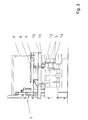
- the ram unit 5 shown on the driver's seat side is arranged laterally behind the driver's cabin 6.
- the ram unit 5 is by means of a boom 7 which the ram unit 5 horizontally displaceable due to its telescopic design sets their distance from the host vehicle 2 on the host vehicle 2 attached. The distance is set using a hydraulic drive unit 8.
- a mounting device 9 for the posts 1 is also attached, the means - not shown in the drawing to erect the horizontally arranged posts 1 in their vertical position and a feed unit for automatic Transport one post 1 into the ram unit 5 is.
- Swivel cylinder 10 can pivot the ram unit 5 be carried out.
- the ram unit 5 is arranged in such a way that positioning movements both horizontally and vertically, pivotable about the vehicle longitudinal axis 11 and about a pivot point rotatable - for vertical positioning of the post - executable are.
- 3 and 4 illustrate in principle further elements for setting the distance of the to be rammed Post 1 in relation to post 1 already rammed (x-direction), its distance from the edge of the road (y direction) and the Single ram height (z direction).
- the pivot frame 12 On the subframe 4, which consists of cross and longitudinal webs made of a U-profile material there is, the pivot frame 12 is pivotally attached. The attachment takes place by means of swivel joints 13, which are arranged eccentrically. This allows the focus relationships define exactly.
- the swivel joints 13 are to execute the swivel movement with a hydraulic drive unit 14 in operative connection.
- swivel frame 12 On the swivel frame 12 is another frame that acts as a sliding frame 15 is formed, attached. It is used for the setting the exact distance between two posts 1 to each other.
- the Rough positioning is done via a computer-controlled and screen-monitored, control arrangement not shown in the drawing realized, the fine positioning in the x direction takes over the sliding frame 15, which has a longitudinal roller guide 16, which is axially adjustable, on the swivel frame 12 is attached.
- the boom 7 On the sliding frame 15, the boom 7 is attached, the Position to post 1 placed first via a light barrier system and the computer control is precisely adjustable.
- the ram unit 5 consists essentially of the driven Ram hammer 17 and the vertical support 18, on the upper and lower Guide elements, in the form of the upper clamping element 19 and lower post guide 20 are attached to the recording and Serve leadership of the post 1. Furthermore, as in FIG. 2 shown, the pivot cylinder 10 is arranged, which is in operative connection with a swivel 21 stands around the pivoting movement of the ram unit 5 to position the post 1 vertically to be able to.
- the subframe 4 - as in Fig. 2nd illustrates - in the area of the superstructures a much smaller one Height up.
- the subframe 4 is in the for stability reasons Essential for the crane construction and can therefore be used in Area of other superstructures at least reduced in height become.
- the carrier vehicle 2 travels with the structures described, loaded with at least a part of those required in an assembly layer Post 1 and a trailer that has additional post supplies, Tools, any other superstructures and the like is loaded to the assembly site.
- the ram unit 5 is located themselves in the transport position, that is, at least partially retracted condition of the telescopic boom 7.
- Das Carrier vehicle 2 is based on a guideline on the road aligned, the vehicle axle is controlled by a hydraulic cylinder lifted from its feathers and blocked.
- the willingness to work of Arrangement is made, that is, the computer arrangement in the Vehicle and the associated control and measurement determination arrangements are activated.
- the one used to calculate the position necessary special data on site, initially using mechanical Measuring devices have been determined are entered, the software program is tailored to the special site conditions customized.
- the ram unit 5 is in the post transfer position brought and there is the first automatic post transfer to the ram unit 5. Then the automatic Positioning the post 1.
- the boom is in the x, y and z directions by means of the telescopic extension, the swivel frame 12 and of the sliding frame 15 aligned.
- the ram unit 5 is adjusted in their ram height, the post 1 is in a defined Move the height above the floor and set it upright.
- the first post 1 is rammed.
- the clamping element 19 and the post guide 20 then open and the ram unit 5 is removed from the post area.
- the Boom 7 moves the ram unit 5 in the transfer position of the new post 1, while the carrier vehicle 2 the next ramming position controlled starts.
- a light barrier system monitors the distance between the carrier vehicle 2 and the first post 1 set and signals the stopping of the carrier vehicle 2 after reaching it the rough position, that is the next insertion point of one Post 1.
- the set positions of the swivel frame 12 and the sliding frame 15 are checked and if necessary newly set, the post height of the post to be rammed 1 and the vertical alignment are on the ram unit 5 by means of the swivel joint 21 in operative connection with the swivel cylinder 10 set that at about the same height on the vertical support 18 is arranged like the sensor for determining the distance.
Applications Claiming Priority (2)
| Application Number | Priority Date | Filing Date | Title |
|---|---|---|---|
| DE10236237 | 2002-08-07 | ||
| DE2002136237 DE10236237B4 (de) | 2002-08-07 | 2002-08-07 | Anordnung zum automatischen Positionieren von Pfosten für Leitplankensysteme |
Publications (2)
| Publication Number | Publication Date |
|---|---|
| EP1388613A2 true EP1388613A2 (fr) | 2004-02-11 |
| EP1388613A3 EP1388613A3 (fr) | 2004-08-04 |
Family
ID=30128767
Family Applications (1)
| Application Number | Title | Priority Date | Filing Date |
|---|---|---|---|
| EP03016402A Withdrawn EP1388613A3 (fr) | 2002-08-07 | 2003-07-21 | Dispositif de positionnement automatique de poteaux pour glissières de sécurité |
Country Status (2)
| Country | Link |
|---|---|
| EP (1) | EP1388613A3 (fr) |
| DE (1) | DE10236237B4 (fr) |
Cited By (4)
| Publication number | Priority date | Publication date | Assignee | Title |
|---|---|---|---|---|
| DE102010023215A1 (de) | 2010-06-09 | 2011-12-15 | Schletter Gmbh | Rammvorrichtung für Pfähle und Verfahren zum Rammen von Pfählen |
| WO2012062241A1 (fr) * | 2010-06-09 | 2012-05-18 | Schletter Gmbh | Mouton pour dispositif de battage |
| CN112095520A (zh) * | 2020-09-22 | 2020-12-18 | 沈昊澎 | 一种绿化带护栏快速固定安装设备 |
| CN112593510A (zh) * | 2020-12-10 | 2021-04-02 | 江西安达交通设施有限公司 | 一种交通护栏智能安装设备 |
Families Citing this family (3)
| Publication number | Priority date | Publication date | Assignee | Title |
|---|---|---|---|---|
| DE102004055320A1 (de) * | 2004-11-16 | 2006-05-24 | Bilfinger Berger Ag | Vorrichtung zur Positionierung eines länglichen Bauteils |
| DE102016114872B4 (de) | 2016-08-11 | 2023-03-30 | Manfred Gross | Montagevorrichtung zum Setzen von Straßenleitpfosten |
| CN209163593U (zh) * | 2019-05-14 | 2019-07-26 | 中铁电气化局集团有限公司石家庄机械装备分公司 | 一种自动安装h型钢柱的设备 |
Citations (5)
| Publication number | Priority date | Publication date | Assignee | Title |
|---|---|---|---|---|
| US3400771A (en) * | 1966-05-09 | 1968-09-10 | Arrow Mfg Company | Mobile percussion unit |
| DE3238945A1 (de) * | 1982-10-21 | 1984-05-03 | Hubert Weisser KG, 7715 Bräunlingen | Vorrichtung zum setzen von schneestangen oder dgl. |
| GB2322390A (en) * | 1997-02-19 | 1998-08-26 | Christopher Warren Gabri Clark | Erecting fence posts |
| DE19717824C1 (de) * | 1997-04-26 | 1998-12-10 | Fraunhofer Ges Forschung | Vorrichtung sowie Verfahren zum Einsetzen von Stangen in den Boden |
| EP1319757A2 (fr) * | 2001-12-14 | 2003-06-18 | Förster Drucklufttechnik GmbH | Montage de poteaux de barrière routière |
Family Cites Families (4)
| Publication number | Priority date | Publication date | Assignee | Title |
|---|---|---|---|---|
| DE2235287A1 (de) * | 1972-07-19 | 1974-01-31 | Karl Obermayer | Verfahren und vorrichtung zum anbringen von sicherheitsleitplanken an strassenraendern od. dgl |
| CA1143958A (fr) * | 1980-05-20 | 1983-04-05 | Victor F. Arnold | Poteaux porteurs de lignes d'electricite et autres |
| US5355576A (en) * | 1993-03-01 | 1994-10-18 | Miller Jack J | Guardrail assembly method and device |
| NL1014524C2 (nl) * | 2000-02-29 | 2001-08-30 | Lodewijk Petrus Maria Minck | Werkwijze voor het tot stand brengen van een vangrail-constructie en middelen voor toepassing van de werkwijze. |
-
2002
- 2002-08-07 DE DE2002136237 patent/DE10236237B4/de not_active Expired - Fee Related
-
2003
- 2003-07-21 EP EP03016402A patent/EP1388613A3/fr not_active Withdrawn
Patent Citations (5)
| Publication number | Priority date | Publication date | Assignee | Title |
|---|---|---|---|---|
| US3400771A (en) * | 1966-05-09 | 1968-09-10 | Arrow Mfg Company | Mobile percussion unit |
| DE3238945A1 (de) * | 1982-10-21 | 1984-05-03 | Hubert Weisser KG, 7715 Bräunlingen | Vorrichtung zum setzen von schneestangen oder dgl. |
| GB2322390A (en) * | 1997-02-19 | 1998-08-26 | Christopher Warren Gabri Clark | Erecting fence posts |
| DE19717824C1 (de) * | 1997-04-26 | 1998-12-10 | Fraunhofer Ges Forschung | Vorrichtung sowie Verfahren zum Einsetzen von Stangen in den Boden |
| EP1319757A2 (fr) * | 2001-12-14 | 2003-06-18 | Förster Drucklufttechnik GmbH | Montage de poteaux de barrière routière |
Cited By (6)
| Publication number | Priority date | Publication date | Assignee | Title |
|---|---|---|---|---|
| DE102010023215A1 (de) | 2010-06-09 | 2011-12-15 | Schletter Gmbh | Rammvorrichtung für Pfähle und Verfahren zum Rammen von Pfählen |
| WO2012010119A2 (fr) | 2010-06-09 | 2012-01-26 | Schletter Gmbh | Procédé et dispositif de battage de pieux |
| WO2012010119A3 (fr) * | 2010-06-09 | 2012-05-10 | Schletter Gmbh | Procédé et dispositif de battage de pieux |
| WO2012062241A1 (fr) * | 2010-06-09 | 2012-05-18 | Schletter Gmbh | Mouton pour dispositif de battage |
| CN112095520A (zh) * | 2020-09-22 | 2020-12-18 | 沈昊澎 | 一种绿化带护栏快速固定安装设备 |
| CN112593510A (zh) * | 2020-12-10 | 2021-04-02 | 江西安达交通设施有限公司 | 一种交通护栏智能安装设备 |
Also Published As
| Publication number | Publication date |
|---|---|
| DE10236237A1 (de) | 2004-02-19 |
| EP1388613A3 (fr) | 2004-08-04 |
| DE10236237B4 (de) | 2008-07-24 |
Similar Documents
| Publication | Publication Date | Title |
|---|---|---|
| DE2752605C2 (de) | Auf einem fahr- oder umsetzbaren Unterbau montierte Vorrichtung zum Einbringen von Beton in Schalungen, insbesondere beim Streckenausbau im Berg- und Tunnelbau | |
| DE102008017961A1 (de) | Betonpumpe mit einer Steuereinheit für die Verteilermastbewegung und einer Regeleinheit für die Fördermengenregelung | |
| DE102006035025A1 (de) | Federbeinpositionierungsvorrichtung | |
| EP1190947A1 (fr) | Véhicule pour la manoeuvre des avions | |
| EP0490927B1 (fr) | Dispositif d'inspection du cote inferieur de ponts | |
| DE10236237B4 (de) | Anordnung zum automatischen Positionieren von Pfosten für Leitplankensysteme | |
| DE4131649A1 (de) | Schleppfahrzeug fuer flugzeuge | |
| DE2835270A1 (de) | Strassenhobel mit einer aufhaengung fuer seine schneidvorrichtung | |
| DE10161651B4 (de) | Verfahren und Anordnung zum Einbringen von Pfosten für Leitplankensysteme in den Boden | |
| DE19921761B4 (de) | Verfahren und Vorrichtung zum Verstellen des Arbeitsabstandes | |
| DE2633683C2 (de) | Transportfahrzeug für Fertiggaragen und dergleichen | |
| DE10127964B4 (de) | Flurförderfahrzeug | |
| EP2088243B1 (fr) | Flèche d'un dispositif de lancement d'un véhicule de pose de pont et procédé de déplacement d'une flèche dans une position de transport de véhicule | |
| DE4409514C2 (de) | Verstellbares Gegengewicht für eine Baumaschine und Hydraulikbagger, der mit einem verstellbaren Gegengewicht ausgerüstet ist | |
| DE3148960A1 (de) | Hydraulikbagger oder hydraulischer kran mit hydraulisch verstellbarem fahrerhaus | |
| DE19521833C2 (de) | Handhabungsgerät für zu demontierende Alt-Kraftfahrzeuge | |
| DE3020770C2 (de) | Fahrzeug für den Ausbau von Gruben und Tunnelbauten | |
| DE19717824C1 (de) | Vorrichtung sowie Verfahren zum Einsetzen von Stangen in den Boden | |
| EP0513623B1 (fr) | Superstructure amovible de véhicules | |
| DE3033400C2 (fr) | ||
| DE1282046B (de) | Vorrichtung zum Kuppeln eines Geraetes fuer den Strassendienst, z. B. eines Schneeraeumgeraets, mit einem Kraftfahrzeug | |
| DE102018214549A1 (de) | Hebeeinrichtung | |
| CH649743A5 (de) | Transportfahrzeug fuer eine raumzelle, insbesondere fuer eine stahlbeton-fertiggarage. | |
| EP0539919B1 (fr) | Dispositif de support pour véhicules spéciaux, notamment pour pompes à béton mobiles | |
| AT406968B (de) | Maschine zur gleislagekorrektur |
Legal Events
| Date | Code | Title | Description |
|---|---|---|---|
| PUAI | Public reference made under article 153(3) epc to a published international application that has entered the european phase |
Free format text: ORIGINAL CODE: 0009012 |
|
| AK | Designated contracting states |
Kind code of ref document: A2 Designated state(s): AT BE BG CH CY CZ DE DK EE ES FI FR GB GR HU IE IT LI LU MC NL PT RO SE SI SK TR |
|
| AX | Request for extension of the european patent |
Extension state: AL LT LV MK |
|
| PUAL | Search report despatched |
Free format text: ORIGINAL CODE: 0009013 |
|
| AK | Designated contracting states |
Kind code of ref document: A3 Designated state(s): AT BE BG CH CY CZ DE DK EE ES FI FR GB GR HU IE IT LI LU MC NL PT RO SE SI SK TR |
|
| AX | Request for extension of the european patent |
Extension state: AL LT LV MK |
|
| 17P | Request for examination filed |
Effective date: 20041115 |
|
| AKX | Designation fees paid |
Designated state(s): AT BE BG CH CY CZ DE DK EE ES FI FR GB GR HU IE IT LI LU MC NL PT RO SE SI SK TR |
|
| 17Q | First examination report despatched |
Effective date: 20071015 |
|
| STAA | Information on the status of an ep patent application or granted ep patent |
Free format text: STATUS: THE APPLICATION IS DEEMED TO BE WITHDRAWN |
|
| 18D | Application deemed to be withdrawn |
Effective date: 20090603 |