EP1388516B1 - Dispositif pour ajuster le répérage d'une découpeuse - Google Patents
Dispositif pour ajuster le répérage d'une découpeuse Download PDFInfo
- Publication number
- EP1388516B1 EP1388516B1 EP20030405564 EP03405564A EP1388516B1 EP 1388516 B1 EP1388516 B1 EP 1388516B1 EP 20030405564 EP20030405564 EP 20030405564 EP 03405564 A EP03405564 A EP 03405564A EP 1388516 B1 EP1388516 B1 EP 1388516B1
- Authority
- EP
- European Patent Office
- Prior art keywords
- web
- strand
- bundle
- strands
- web strand
- Prior art date
- Legal status (The legal status is an assumption and is not a legal conclusion. Google has not performed a legal analysis and makes no representation as to the accuracy of the status listed.)
- Expired - Lifetime
Links
- 238000007639 printing Methods 0.000 claims abstract description 71
- 238000005520 cutting process Methods 0.000 claims abstract description 62
- 238000000034 method Methods 0.000 claims abstract description 19
- 230000001105 regulatory effect Effects 0.000 claims abstract description 10
- 238000004519 manufacturing process Methods 0.000 claims description 24
- 230000008859 change Effects 0.000 claims description 18
- 238000012546 transfer Methods 0.000 claims description 2
- 238000011144 upstream manufacturing Methods 0.000 claims 2
- 230000001276 controlling effect Effects 0.000 claims 1
- 230000004075 alteration Effects 0.000 abstract 1
- 230000015572 biosynthetic process Effects 0.000 description 10
- 238000004904 shortening Methods 0.000 description 7
- 239000002699 waste material Substances 0.000 description 7
- 238000006073 displacement reaction Methods 0.000 description 6
- 230000009467 reduction Effects 0.000 description 6
- 230000008901 benefit Effects 0.000 description 2
- 239000000463 material Substances 0.000 description 2
- 239000010893 paper waste Substances 0.000 description 2
- 238000003860 storage Methods 0.000 description 2
- 230000009471 action Effects 0.000 description 1
- 238000006243 chemical reaction Methods 0.000 description 1
- 239000003086 colorant Substances 0.000 description 1
- 238000012937 correction Methods 0.000 description 1
- 230000002596 correlated effect Effects 0.000 description 1
- 230000000875 corresponding effect Effects 0.000 description 1
- 230000008878 coupling Effects 0.000 description 1
- 238000010168 coupling process Methods 0.000 description 1
- 238000005859 coupling reaction Methods 0.000 description 1
- 238000013461 design Methods 0.000 description 1
- 230000000694 effects Effects 0.000 description 1
- 238000005516 engineering process Methods 0.000 description 1
- 238000005259 measurement Methods 0.000 description 1
- 238000005457 optimization Methods 0.000 description 1
- 230000037361 pathway Effects 0.000 description 1
- 230000000737 periodic effect Effects 0.000 description 1
- 230000004044 response Effects 0.000 description 1
- 238000010408 sweeping Methods 0.000 description 1
- 230000001360 synchronised effect Effects 0.000 description 1
- 238000010023 transfer printing Methods 0.000 description 1
- 238000009941 weaving Methods 0.000 description 1
Images


Classifications
-
- B—PERFORMING OPERATIONS; TRANSPORTING
- B65—CONVEYING; PACKING; STORING; HANDLING THIN OR FILAMENTARY MATERIAL
- B65H—HANDLING THIN OR FILAMENTARY MATERIAL, e.g. SHEETS, WEBS, CABLES
- B65H35/00—Delivering articles from cutting or line-perforating machines; Article or web delivery apparatus incorporating cutting or line-perforating devices, e.g. adhesive tape dispensers
- B65H35/02—Delivering articles from cutting or line-perforating machines; Article or web delivery apparatus incorporating cutting or line-perforating devices, e.g. adhesive tape dispensers from or with longitudinal slitters or perforators
-
- B—PERFORMING OPERATIONS; TRANSPORTING
- B65—CONVEYING; PACKING; STORING; HANDLING THIN OR FILAMENTARY MATERIAL
- B65H—HANDLING THIN OR FILAMENTARY MATERIAL, e.g. SHEETS, WEBS, CABLES
- B65H23/00—Registering, tensioning, smoothing or guiding webs
- B65H23/04—Registering, tensioning, smoothing or guiding webs longitudinally
- B65H23/046—Sensing longitudinal register of web
-
- B—PERFORMING OPERATIONS; TRANSPORTING
- B65—CONVEYING; PACKING; STORING; HANDLING THIN OR FILAMENTARY MATERIAL
- B65H—HANDLING THIN OR FILAMENTARY MATERIAL, e.g. SHEETS, WEBS, CABLES
- B65H23/00—Registering, tensioning, smoothing or guiding webs
- B65H23/04—Registering, tensioning, smoothing or guiding webs longitudinally
- B65H23/18—Registering, tensioning, smoothing or guiding webs longitudinally by controlling or regulating the web-advancing mechanism, e.g. mechanism acting on the running web
- B65H23/188—Registering, tensioning, smoothing or guiding webs longitudinally by controlling or regulating the web-advancing mechanism, e.g. mechanism acting on the running web in connection with running-web
- B65H23/1882—Registering, tensioning, smoothing or guiding webs longitudinally by controlling or regulating the web-advancing mechanism, e.g. mechanism acting on the running web in connection with running-web and controlling longitudinal register of web
- B65H23/1886—Synchronising two or more webs
-
- B—PERFORMING OPERATIONS; TRANSPORTING
- B65—CONVEYING; PACKING; STORING; HANDLING THIN OR FILAMENTARY MATERIAL
- B65H—HANDLING THIN OR FILAMENTARY MATERIAL, e.g. SHEETS, WEBS, CABLES
- B65H35/00—Delivering articles from cutting or line-perforating machines; Article or web delivery apparatus incorporating cutting or line-perforating devices, e.g. adhesive tape dispensers
- B65H35/04—Delivering articles from cutting or line-perforating machines; Article or web delivery apparatus incorporating cutting or line-perforating devices, e.g. adhesive tape dispensers from or with transverse cutters or perforators
-
- B—PERFORMING OPERATIONS; TRANSPORTING
- B65—CONVEYING; PACKING; STORING; HANDLING THIN OR FILAMENTARY MATERIAL
- B65H—HANDLING THIN OR FILAMENTARY MATERIAL, e.g. SHEETS, WEBS, CABLES
- B65H2301/00—Handling processes for sheets or webs
- B65H2301/40—Type of handling process
- B65H2301/41—Winding, unwinding
- B65H2301/414—Winding
- B65H2301/4148—Winding slitting
-
- B—PERFORMING OPERATIONS; TRANSPORTING
- B65—CONVEYING; PACKING; STORING; HANDLING THIN OR FILAMENTARY MATERIAL
- B65H—HANDLING THIN OR FILAMENTARY MATERIAL, e.g. SHEETS, WEBS, CABLES
- B65H2801/00—Application field
- B65H2801/03—Image reproduction devices
- B65H2801/21—Industrial-size printers, e.g. rotary printing press
-
- Y—GENERAL TAGGING OF NEW TECHNOLOGICAL DEVELOPMENTS; GENERAL TAGGING OF CROSS-SECTIONAL TECHNOLOGIES SPANNING OVER SEVERAL SECTIONS OF THE IPC; TECHNICAL SUBJECTS COVERED BY FORMER USPC CROSS-REFERENCE ART COLLECTIONS [XRACs] AND DIGESTS
- Y10—TECHNICAL SUBJECTS COVERED BY FORMER USPC
- Y10T—TECHNICAL SUBJECTS COVERED BY FORMER US CLASSIFICATION
- Y10T83/00—Cutting
- Y10T83/04—Processes
- Y10T83/0524—Plural cutting steps
Definitions
- the invention relates to a printing machine with a Thomasstelten register in which an endlessly conveyed web is printed or preferably a plurality of such webs are printed. Furthermore, the invention relates to a method for adjusting the cut register of printed web strands obtained from one or more webs by slitting.
- the printing machine is preferably a web-fed printing press in which the web or the plurality of webs are each unwound from a roll continuously. More preferably, the invention is used in web-fed rotary printing of large newspaper editions. From the DE 89 15 642 U1 a device for reducing waste in web-fed rotary presses is known.
- the web or, more usually, a plurality of webs are continuously printed with at least two juxtaposed printed images. As seen in the conveying direction, the web can be successively printed each with the same print image or a periodic sequence of two or basically even more different print images. Between the juxtaposed printed images, the web or the multiple webs is cut longitudinally into web strands. Several web strands are combined into a bundle according to the current print production and cut together across the conveying direction of the respective bundle, in order to obtain the individual printed products, for example newspapers or magazines. In newspaper printing, several bundles are generally merged together to obtain the printed product and cut together across.
- the web strands which each form a bundle, are brought together so that the printed images of the web strands of a bundle are centered as accurately as possible between two consecutive sections in the conveying direction.
- the web strands of a bundle are used to obtain their so-called cut register, i. for centering between cuts, influenced by appropriate operations. In relation to the individual web strand, these operations are changes to the path length made specifically for the cutting register of the relevant web strand, which the web strand travels between the location of the printing and the location of the transverse cutting.
- cutting register rollers For the adjustment of the cutting register, cutting register rollers have proven themselves.
- the cut register rollers are each looped around by a web strand, usually by 180 °.
- a cutting register roller By an adjusting movement of a cutting register roller transversely to its longitudinal axis, the path of the track looping around it is lengthened or shortened and in this way the cutting register of the relevant web strand is adjusted.
- two or three web strands are obtained from the web by the longitudinal cutting, which are brought together and longitudinally folded.
- the web strands are individually subjected to one or more suitable turning operations.
- Such a web strand is hereinafter referred to as direct strand.
- a web strand which is subjected to one or more turning operations is given the name twisting strand for distinction below.
- Printing machines and methods of web guide of the type described above relates to the invention in particular also.
- the cut register position is readjusted by adjusting the web length of the respective turn strand at the beginning of a new print production, or is adjusted in current print production to accommodate changes in the direct strand position.
- the setting of the cutting register position of the direct line is not affected by this.
- the direct strand forms, so to speak, the leading strand to which all other web strands of the bundle are adjusted.
- One problem is the setting of the machine to a new print production.
- the setting is required when starting the machine or when changing the print production while the machine is running.
- the demands on the flexibility of the machine increase. Due to the increasing cost pressure, however, the waste of waste is becoming more and more important.
- the invention has recognized that reducing the settling time required to set the cut register position of web cords can make a significant contribution to paper waste reduction. This applies to the flying change from a print production to a new print production when the printing press continues to run and, in particular, applies also for those cases where a new web start is fed into the press for the new print production.
- the subject of the invention is the setting of the cut register in a new print production, namely the setting up to the time from which all cut register positions of the web strands of a web strand bundle of the new printed product are set.
- the subject of the invention is the setting of the cut register in a current print production to prevent after completion of a basic setting in the current print production that intolerable deviations occur in the Schnlttreglsterposmon of one or more of the web strands of the bundle.
- a web is printed continuously with printed images.
- the printed or yet to be printed web is cut longitudinally into a first web strand and at least one second web strand. If the web is printed transversely to its conveying direction with two or three printed images arranged next to one another, as is usual in web-fed rotary printing, the web is cut longitudinally between the already printed or still to be printed images in accordance with two or three web strands.
- the invention is not limited to this preferred application, ie, for example, also relates to a longitudinal section in more than three web strands.
- one or more web-strand bundles are formed.
- the web strands obtained from the web alone or together with one web strand or several web strands of another web or several further webs can form the single or one of the plurality of web strand bundles.
- a part of the web strands obtained from the web may form a web strand bundle alone or together with one or more web strands of one or more world webs, the same also being valid for the remaining other part of the web strands being fed from the web.
- the web strands obtained from the web are combined with one another and / or with other web strands to form the web strand bundle or the plurality of strand bundles.
- At least one web strand bundle is cross-cut, i. it is cut transversely to the conveying direction of the web strand bundle between two successive printed images.
- Cross cutting can be carried out jointly for several web bundles, as is common, for example, in the printing of newspaper editions.
- the invention also relates to the case that only a single web strand bundle is formed and cross-cut.
- the lengths of the paths of the web strands are adjusted by path length changes in a coordinated manner.
- the path lengths of the web strands are in each case measured from the location of the formation of the relevant web strand, generally the location of the longitudinal cutting, to the location of the merging of the web strands of the bundle.
- at least one deflecting device is arranged in the strand path between the place of formation and the merging for each of the web strands of the bundle.
- the deflection devices each form a deflection axis about which the assigned web strand is deflected.
- the deflection axes are adjustable by Verstellwegenburgn.
- the deflection devices may in particular be cut register rollers or in principle also other types of suitable adjustment directions.
- the path lengths of the web strands are so adjusted or changed, i. the required per track strand Verstellwegn the associated deflection or deflection axis chosen so that a largest of Strangwegin S urge is minimized. It is thus not one of the web strands of the bundle determined as a Leitstrang on the cut register position, the cut register positions of the other web strands are set, but it is chosen for each web strand of the bundle such Verstellwegfar for the associated deflector that a largest of the Verstellwegin is smaller than they it would be if one of the web strands of the bundle were designated as a fixed leader for the other web strands of the bundle. According to the invention, therefore, no Leitstrang firmly predetermined, but it is the Verstellwegdorfn and resulting from the Verstellweginn length changes of the strand paths are dimensioned to minimize the maximum Verstellwegenstein.
- the Verstellwegenburgn chosen so that a largest of the Verstellwegenburgn is minimized.
- a control and / or regulating device individually determines an adjustment path length for each of the web strands of the bundle with the stipulation that a largest adjustment path length resulting from the determination is minimized.
- the displacement lengths are chosen not to minimize the greatest displacement length, but "only" in the direction of such minimization. If, for example, only two web strands form the bundle, then in the optimum embodiment variant in which the greatest of the displacing path lengths is minimized, the adjustment path lengths for both web strands are chosen to be equal in magnitude and opposite in sign.
- the path length of one of the web strands is changed to a lesser extent than in the optimal embodiment, but such that the required for obtaining the correct cut register position of both web strands path length change of the other of the web strands, in the assumed Example case of the turning strand, is shorter than it would be if the path length change for the first web strand would not be made.
- the path length of one or more of these web strands is neither lengthened nor shortened.
- Each of the web strands of the bundle may be a web strand, the path length of which is not changed for the setting of the web strands of the bundle to be made from the initial state, depending on the initial state existing before the adjustment.
- the printing machine comprises for each web strand of the bundle a deflection device which forms at least one transversely adjustable deflection axis for the relevant web strand.
- the at least one adjustable deflecting axis per track is adjustable transversely to itself by a maximum Verstellweglos.
- the maximum displacement length is so great for each of the transversely adjustable deflection axes that the displacement paths between the transversely adjustable deflection axes can be divided.
- the maximum Verstellwegin each of the transversely adjustable deflection axes is so large that in the case of merging all formed from a single web web strands, the adjustment paths between these deflection axes can be divided.
- the maximum Verstellweginn the transversely adjustable deflection axes are the same size, so that the Verstellweginn between the web strands can be divided evenly.
- an object of the invention is already achieved when the maximum Verstellwegin while different in size, but still a division of the adjustment paths between the deflection axes can be made in a relevant for the shortening of the setting time extent.
- a mobility of the transversely adjustable steering axles is at least considered even if the maximum Verstellwegenburghold by more than 50%, ie if a smallest of the maximum Verstellwegenburgn is at least half as large as a maximum of the maximum Verstellwegluin.
- the invention results in the adjustment of the cut register position of the direct strand to reduction or preferably minimizing the largest Verstellwegm that make for one or more of the web strands of the bundle of direct strand concerned is, is performed.
- the invention sets the settling time as compared with conventional ones Setting method with predetermined guide strand reduced. As the set time required to set the cut register positions is reduced, waste can also be reduced, provided that other settings of the machines can be made in parallel within the set time, such as setting the register of color transfer printing cylinders.
- the execution of the path minimization described above as optimal is strictly optimal only if the setting properties of the cut register setting members are the same. However, this does not have to be the case.
- the actuating speeds of the cut register adjusting members can be varied to adjust at a suitable speed depending on certain operating parameters, for example, depending on the web speed, a material property of the web material such as modulus and / or web thickness and / or Wet pressure depending on the strand moisture.
- the path length change which is the largest in terms of magnitude is a shortening for one web strand of the bundle and an extension for another web strand of the bundle, the shortening is preferably carried out with the greatest positioning speed.
- the maximum path length change after the reduction or even minimization is a shortening, since in this case the setting time can be minimized.
- the cutting register adjusting device accordingly comprises a control device which may be further developed into a control device which allows such a variation of the positioning speed and preferably calculates the optimum positioning speed individually for the trains based on the stored and selected or adjusted production configuration and controls or regulates the adjusting members accordingly ,
- the reversing strand diverter of the bundle i. for a web strand which is turned prior to the formation of the bundle is preferably arranged in front of the turning bar region for this turning strand. If one of the plurality of web strands obtained from a web is conveyed unfavorably into the bundle, the deflecting device for such a direct strand is preferably arranged in spatial proximity to the reversing device of the reversing strand.
- the diverters for the web strands of the web are arranged in a preferred embodiment of the invention so that a not yet longitudinally cut web can be pulled around the deflectors simultaneously, whereby the machine web feed is considerably facilitated.
- no other deflection devices are arranged between the deflection, which are wrapped only by a single of the web strands of the web.
- they are even arranged side by side in the sense that no other deflection devices for the web are arranged on the path of the web between them.
- the web feeder is cut longitudinally only when the web has been pulled in by the cut register adjusting device thus formed.
- the arrangement of the reversing device for the single or multiple turning strands of the web in front of the turning bar device has the further advantage over the simplification of a machine web take-in that the associated deflecting the width of a simple strand and not more, as before, have at least twice the strand width got to.
- two baffles are arranged transversely to the web strands in close proximity to each other, they are preferably supported on only one side of the frame, while each projecting with a free end towards the other frame side.
- the two deflection devices can preferably be brought into a position in which they are aligned with one another and form a preferably cylindrical, smooth, uniform surface for the web to be pulled in.
- the deflecting device for the third web is preferably likewise arranged in front of the turning bars, in particular the third deflecting device can be arranged next to the other two.
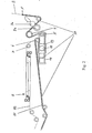
- FIG. 1 shows the path of a web B through a web-fed rotary printing press for newspaper printing.
- the web B is unwound from a roll that is rotatably mounted in a reel changer 1 and conveyed in a conveying direction F by a printing unit 2. It is printed on both sides in the printing unit2.
- the printing unit 2 comprises two blanket cylinders 2a, between which a printing gap for the continuous web B is formed.
- the blanket cylinders 2a are each associated with a printing form cylinder 2b.
- the printing form cylinders 2 b transfer their printed images, which are in the form of images with printing ink, onto the blanket cylinders 2 a, from which they are finally printed on the web B.
- the blanket cylinders 2a are preferably not mechanically coupled to each other, but are each driven by a separate drive motor electronically synchronized and drive in turn via a respective mechanical gear on the associated printing form cylinder 2b.
- the printing form cylinder 2b carry at its periphery in the cylinder longitudinal direction side by side at least two printing plates, the printed images are imaged on the web B accordingly side by side.
- a single or it may, as usual, two printing plates or in principle even more printing plates are provided one behind the other on the printing forme cylinders 2b.
- the printing plates have seen in the cylinder longitudinal direction depending on the width of an open newspaper.
- the web B is cut longitudinally after printing by means of a longitudinal cutting device between the printed images.
- the longitudinal cutting device is formed by a cutting roller 3a and a counter-roller 3b, which are each arranged to one side of the web B opposite to each other.
- the web strands B 1 and B2 are then conveyed together via a tension roller 4 to a cutting register adjustment device 10.
- the paths of the web strands B1 and B2 are separated.
- the first web strand B1 is guided from the cut register setting device 10 only via web guiding means without turning or weaving operations to a longitudinal folding device 9, which is preferably designed as a folding hopper.
- the second web strand B2 runs out of the cut register adjustment device 10 and into a turning bar device 8.
- the second web strand B2 is turned and / or swept and then brought together via an inlet roller of the longitudinal folding device 9 with the first web strand B1 to form a web strand bundle, which consists in the embodiment only of the two web strands B1 and B2.
- the web strands B1 and B2 lying one above the other in the bundle are longitudinally folded together during the passage through the longitudinal folding device 9 and conveyed into a transverse cutting device 25.
- the cross-cutter 25 may be a cutting cylinder of a folder as commonly used in newspaper web-fed rotary printing.
- the longitudinally folded and cross-cut single copies of printed products are designated P. If it is, as in the embodiment, newspaper copies, they are still cross-folded after the cross-cutting, to finally get the newspaper copies.
- a web-strand bundle consisting only of the web strands B1 and B2 can form a printed product P after the cross-cutting, further web strands bundles B1 / B2 are formed in newspaper printing and the cross-cut webs are then cross-cut in the transverse cutting device 25 ,
- the cut register adjustment device 10 By means of the cut register adjustment device 10 it is ensured that the printed images of the web strands B1 and B2 always come to lie between two successive sections of the crosscutting device 25 and are appropriately centered between the sections of the practice, i. are sufficiently accurately positioned with respect to the common cut register. For this positioning, the different paths of the web strands B1 and B2 from the pressure to the location of the merge in the longitudinal folding device 9 and, if necessary, an offset of the juxtaposed printing forms of the printing form cylinder in the circumferential direction, i. an offset of the printed images of the first web strand B1 to the printed images of the second web strand B2 in the conveying direction F, be compensated.
- the cutting register adjustment device 10 comprises two deflection devices, namely a first deflection device 11 and a second deflection device 12, and also a deflection roller 5 at the inlet the deflecting devices 11 and 12 and a further deflecting roller 6 at the outlet from the deflecting devices 11 and 12.
- the two web strands B1 and B2 each wrap around the inlet guide roller 5 and also the outlet guide roller 6 in common, i. parallel next to each other. At the outlet deflection roller 6, the web strand paths separate.
- the first web strand B1 is passed without turning or Kehroperationen through the area of the turning bar device 8.
- the first web strand B1 can therefore also be referred to as a direct strand.
- the second web strand B2 runs from the outlet guide roller 6 via an inlet roller 7 in a turning bar plane of the turning bar device 8, and is turned there by appropriate web guide and / or swept and ansch manend merged with the first web strand B1.
- the second web strand B2 can therefore also be referred to as a reversing or sweeping strand.
- the first web strand B1 is guided via the first deflection device 11 and the second web strand B2 via the second deflection device 12 and deflected about the deflecting axis formed by the respective deflection device 11 or 12.
- the inlet guide roller 5 and the outlet guide roller 6 are arranged to the deflection devices 11 and 12 so that the first web strand B1, the first deflecting device 11 and the second web strand B2, the second deflecting device 12 each loop through 180 °, so that the web strands B1 and B2 each run parallel to their deflection 11 or 12 and run away from it.
- the two guide rollers 5 and 6 are stationary, but rotatably mounted roller body.
- the deflection devices 11 and 12 are also each formed by a rotatably mounted roller body. Both deflection devices 11 and 12 are mounted transversely to their axes of rotation, which at the same time also form said deflection axes, linearly movable back and forth along a common axis of movement in a common plane of movement.
- the direction of mobility (movement axis) has parallel to the incoming from the inlet guide roller 5 to the deflecting means 11 and 12 and from the deflecting means 11 and 12 to the outlet guide roller 6 expiring web strands B1 and B2.
- the direction of reciprocation is indicated at the deflection 11 and 12 each with a double arrow.
- the arrangement of the cut register adjustment device 10 in the path of the second web strand B2, i. of the turning strand, in front of the turning bar device 8, has the advantage that its deflecting device 12, which influences the cutting register position, can be executed in the width of the second web strand B2 and not, as in the conventional arrangement behind the turning bar device 8, the double web strand width.
- the adjustment of the cut register for the second web strand B2 before performing the turning and / or Kehroperation also allows the automated collection of the web start of a new web to behind the cut register adjustment device 10 for the second web strand B2.
- FIG. 2 a guideway 17 of a machine and in this sense automatic Brueinzugssystems is located.
- the guideway 17 is formed by guide rails, which are arranged on one side next to the Bruleitffenn and serve the leadership of a driven pulling-in means.
- the guide track 17 leads around the deflection devices 11 and 12 of the cutting register adjustment device 10.
- the guide track 17 is also guided around the entry guide roller 5 and the exit guide roller 6 and further along the path of the first track B1.
- FIG. 3 shows the web B in this state immediately after machine retraction over the entire path of the later first track B1.
- the rollers 3a and 3b of the slitter are moved against each other and the web B is cut longitudinally between the later printed images.
- the web start of the second web strand B2 is manually from the outlet guide roller 6 via the inlet roller 7 for the turning bar device 8, by the turning bar device. 8 through and fed through the downstream Bruleitstoff.
- the manual retraction via a deflection of a cutting register adjustment device is saved, which brings Zeitvortelle and contributes to the reduction of Einziehêtn.
- FIG. 4 shows the web B after the longitudinal cutting and before the formation of a web start for the second web strand B2.
- FIG. 1 is also a control and regulating device shown, which serves the control and regulation of the adjustment movements of the two deflection devices 11 and 12.
- the control and regulating device comprises two sensors 23 and 24, a control and regulating member 20 and two motor actuators 21 and 22.
- the sensor 23 detects the position of the printed image on the passing below him first web strand B1, and the sensor 24 detects the position of the printed image on the traversing under him second track B2.
- the position signals of the sensors 23 and 24 are supplied to the control and regulating member 20.
- the control and regulating member 20 charged the two sensor signals by means of a suitable algorithm and forms from this by comparison with input command signals, the control signals for the actuators 21 and 22.
- the actuator 21 is coupled to the first deflection 11 and the actuator 22 to the second deflection 12.
- the actuators 21 and 22 act on the deflection devices 11 and 12 in accordance with the actuating signals formed by the control and regulating member 22, ie they effect the adjustment movement of the deflection devices 11 and 12 along their common axis of movement.
- the control and regulating member 20 with the sensors 23 and 24 and the actuators 21 and 22 forms a control for the setting of the correct cut register position for each of the web strands B1 and B2.
- these members form a control and regulation until the receipt of a basic setting.
- the Figures 3 and 4 The cut register setting device 10 and its immediate vicinity each show the same view in a three-dimensional representation, but in two different states of the cut register setting device 10.
- the states are differentiated by the positions which the deflection devices 11 and 12 occupy with respect to each other.
- the formation of the two deflection devices 11 and 12 each as a strand width, circular cylindrical, smooth roll body. Due to the design as only single-width roll body, the deflecting devices 11 and 12 can be arranged side by side in a small space.
- the arrangement and movable mounting of the deflectors 11 and 12 is such that they are in a first state, which in FIG.
- roller body forms when pulling the web start of a new web a simple guide roller.
- the inevitable clear gap between the free ends of the roll body is kept so narrow within the tolerances that it can be neglected for the entry of the web B. In this sense, the roll body is uniform.
- the deflecting axes formed by the deflecting devices 11 and 12 are aligned in the first state.
- the deflecting devices 11 and 12 each assume their starting base position relative to each other, in which a web with a free web beginning is pulled in.
- the baffles 11 and 12 can be moved apart in opposite directions by means of the actuators 21 and 22, for example in the in FIGS Figur4 shown second state in which their deflection axes are offset parallel to each other at a maximum distance.
- the deflection devices 11 and 12 assume positions in which the path path of the first web strand B1 has a minimum length and the path path of the second web strand B2 has a maximum path length.
- the diverters 11 and 12 can be moved from the position they take in the first state to its other two extreme positions, if required by the cut register control.
- Intermediate states are of course also adjustable, preferably continuously.
- the deflecting devices 11 and 12 are each guided linearly guided on their outer, mutually remote axial ends on one side of a frame along the axis of movement.
- the frame side, on which the first deflecting device 11 is mounted, is denoted by 14, and the frame side, on which the second deflecting device 12 is mounted, is designated by 16.
- the frame sides 14 and 16 each form a parallel to the axis of movement guideway.
- the deflection 11 and 12 are each rotatably mounted on one of two carriages 13 and 15, which is linearly stirred along the guide path formed by its frame side 14 or 16.
- the deflecting axes formed by the deflecting devices 11 and 12 each have a right angle to the guideways formed by the frame sides 14 and 16.
- the adjustability of the deflection 11 and 12 is designed by their storage and the coupling with the actuators 21 and 22 so that the necessary for the positioning of the cut register of the two web strands B 1 and B2 adjustment movements can be divided on the deflection 11 and 12, preferably at least substantially half each, more preferably exactly half of each. Accordingly, the maximum lengths of the adjustment of the deflectors 11 and 12 are the same. Due to the advantageous storage of the deflectors 11 and 12 immediately next to each other, the adjustment paths are even the same, i. the deflecting axis formed by the first deflecting device 11 and the deflecting axis formed by the second deflecting device 12 can be reciprocated between the two same outer extreme positions. The two deflection devices 11 and 12 are therefore equivalent in the ideal case described by way of example.
- the adjustability of the first deflector 11 opens up new possibilities for adjusting the cut register of the direct strand and the turning strand, i. for the control and / or regulation of the web strands B1 and B2.
- the cutting register In the adjustment of the cutting register is conventionally existing between direct strand and reversing strand difference in the positions of the respective print images alone by changes in length the path of the turning strand compensated.
- the printing unit ensures that the printed image on the direct line is positioned in the cut register.
- An adjustment of the length of the path of the direct line is made at best to a limited extent, this adjustment is not carried out in relation to the cut register of the other web strand or the cut registers of the several other web strands of the bundle, but solely with respect to the position of Section in the cross cutter.
- the path length of a strand is understood to be the length of the path of the relevant strand from its formation, that is to say the location of the longitudinal cutting up to the merging in the strands B1 and B2.
- the direct strand is the guide strand of the bundle to which the other web strands of the bundle are adjusted.
- This type of cut register setting requires, in the case of the other web strand or the several other web strands of the bundle, large adjustment paths for their adjustment devices serving for the adjustment.
- the adjustment paths are typically of the order of 200 to 400 mm. On the other hand, the speed of the adjustment is limited.
- a linear register as each of the deflecting means 11 and 12 represents a, the strand path according to experience to extend by a maximum of 1 mm per meter. If, for example, an adjustment travel, ie register travel, of 300 mm is required in order to switch from a print production to another print production with uninterrupted print production, at least 300 web meters pass through the printing press before the cut register is readjusted. If the print products are newspaper copies whose length is 1 m to simplify the estimation, then the new cut register is only set after 300 printed copies. The first 300 printed copies of the new production are waste paper.
- the adjustment movement required for the cutting register adjustment can now be divided between the two web strands B1 and B2. More generally, the adjustment path for the turning strand of the web strand bundle is reduced by a part thereof, preferably half of the adjustment path for the turning strand, from the Thomasregistereinstellglied for the direct strand, in the embodiment, the first deflection 11, is taken over.
- the total Verwellweg required is preferably divided evenly. If the direct strand is combined with several web strands into a bundle, the adjustment paths are preferably divided as evenly as possible on the web strands to be joined. The adjustment is advantageously carried out under the optimization strategy that the positioning time is minimal assuming the same adjustment speeds for the setting of the cutting register.
- the path of the first track B1 is extended to the same extent as the track of the second track B2 is shortened.
- the path length changes to be made can also be a setting in the opposite direction, ie a shortening of the path of the first track B1 and extending the path of the second Brustrangs B2 be advantageous.
- the reduction of the length of the adjustment path of the second deflection device 12 is particularly advantageous in the case of a change from one printed product to another in the case of continued printing production, since the waste can be considerably reduced.
- the new cut register setting may result in the first web strand B1 not being in register with the cut due to the change in length of its path even if the color register (s) were in register prior to adjustment with the cut.
- the direct, first web strand B1 is otherwise brought into the register with the cut, for example by means of a registration roller for the web B or preferably by a coordinated adjustment of the personallysreglster the color transferring to the web B cylinder.
- the cross-cutting device can be adjusted in accordance with the path length changes of the web strands B1 and B2.
- both the circumferential register of the color-transmitting cylinder and the cross-cutting device can be adjusted adjusted.
- This part of the registration is carried out jointly with all web strands B1 and B2 of the same web B or all web strands of the bundle. Pathway and strand-wise registration are matched for the cut per bundle and preferably executed simultaneously.
- the said on the basis of the embodiment with respect to the register by means of these further cut register adjusting members applies also to the general case of the invention, in which the considered web strand bundle on the web strands B1 and B2 also contains one or more further web strands or only one of the web strands B1 and B2.
- the invention is already advantageous for a printing machine for a single-sided, monochrome printing or a two-sided printing in a single printing nip of a printing unit, as for the purposes of explaining a reference to the FIG. 1 is described.
- the printing machine can have a plurality of printing units of this type, ie rubber-rubber printing units, and / or of other types, for example satellite printing units, wherein the different types of printing units are arranged and operated such that the web B is multicolored or a plurality of webs B is or will be printed in one or more colors.
- each of the web-contacting and color printing on the web cylinder is ever driven by a separate motor, wherein the required synchronization of the respective cylinder is not mechanically, but signal technology, such as electronic, made.
- This type of formation of the pressure points is advantageous in view of the adjustment of the color register, with which preferably the adjustment of the direct strand B 1 is compensated for cutting.
- a cut register adjustment device 10 is preferably arranged in each case and also preferably has the further features of this adjustment device.
- the web strands B1 and B2 are combined, for example, with a third web strand B3 to form a bundle and the position difference of the second web strand B2 for cutting, for example, 300 mm and the position difference of the third web strand B3 for cutting, for example, 400 mm, while the first web strand B1 at the moment
- the strand path length change required in the conventional adjustment method would be 300 mm for the second web strand B2 and 400 mm for the third web strand B3, while nothing would be compensated for in the first web strand B1 and the displacement of the first deflecting device 11 would therefore be "zero".
- the largest Strangwegin Sung and largest Verstellwegn the respective deflection would be required for the third track B3. Its deflection would have to be moved by the largest Verstellwegin from its original position.
- the total required response time would correspond to the time that would be required to move the deflection device for the third web strand B3 from its initial position taken before the adjustment by the adjustment path length required for a strand path length change of 400 mm.
- the path length of the first web strand B1 is lengthened by 200 mm in the most optimal embodiment variant of the adjustment method according to the invention, in which the largest of the adjustment path lengths is minimized. Accordingly, the path of the second web strand B2 does not have to be shortened by 300 mm, but only by 100 mm. In particular, however, the largest of the Strangwegzen Sungen to be performed, namely that for the third web strand B3, significantly reduced. The shortening of the path length required for the third track B3 is no longer 400 mm, but only 200 mm. In the example, this corresponds to the minimum of the path length change for the third track B3.
- the largest of the adjustment path lengths by which one of the deflection devices must be adjusted is 100 mm.
- the first deflecting device 11 must be adjusted by 100 mm for an extension and the deflection device for the third web strand B3 by also 100 mm for a magnitude equal in magnitude shortening of the relevant strand path.
- the largest of the strand path length changes and the largest of the path lengths were minimized.
- the invention is not limited to such absolute minimization but also includes suboptimal embodiments of the adjustment method.
- the path of the first track B1 is extended only by 150 mm, for example, and accordingly the path of the second track B2 is shortened by 150 mm and the path of the third track B3 is shortened by 250 mm to bring all three web strands B1, B2 and B3 to the same cut register position.
- the third web strand B3 may be a web strand which is obtained by longitudinal cutting from the same web B as the first web strand B1 and the second web strand B2.
- the third web strand B3 need not be from the same web B as the other two web strands B1 and B2, but may have been obtained from another web by slitting. In fact, it may even have been handled directly in web width from a roll.
- the adjustment method according to the invention the arrangement according to the invention of individual or all cut register setting members for the web strands in front of the turning bars and also the arrangement of the cut register setting members per web for their strands in mutual spatial proximity are present in many different web guides, which lead to the formation of web strand bundles, advantageous.
Claims (15)
- Procédé de réglage du repérage de coupe pour et/ou dans une production d'impression, dans lequela) une bande (B) avec des images d'impression est imprimée en continu,b) la bande (B) est découpée longitudinalement en un premier brin de bande (B1), par exemple le brin direct, et au moins un second brin de bande (B2),c) le premier brin de bande (B1) est réuni avec au moins le second brin de bande (B2) et/ou au moins un autre brin de bande, en un faisceau de brins de bande,d) et le faisceau de brins de bande est découpé transversalement entre des images d'impression se succédant dans la direction de transport (F),e) et dans lequel les longueurs des courses des brins de bande (B1, B2) du faisceau sont modifiées, avant la réunion, de variations de longueur de course qui sont telles que les positions du repérage de coupe, rapportées à la coupe transversale, des brins de bande (B1, B2), soient réglées,f) pour le premier brin de bande (B1), la variation de longueur de course étant choisie de manière que la plus grande des variations de longueur de course soit inférieure, à ce qu'elle serait, si la longueur de course du premier brin de bande (B1) n'était pas modifiée,
caractérisé en ce queg) la plus grande des variations de longueur de course est minime. - Procédé selon la revendication 1, caractérisé en ce que pour chacun des brins de bande (B1, B2) du faisceau, la variation de longueur de course est choisie dans le but de réduire, de préférence dans le but de minimiser, les plus grandes des variations de longueur de course.
- Procédé selon l'une quelconque des revendications 1 ou 2, caractérisé en ce qu'au moins l'un des brins de bande (B1, B2) du faisceau est retourné et/ou inversé avant la réunion et en ce que la variation de longueur de course pour le brin de bande (B2) retourné et/ou inversé est exécutée avant le retournement et/ou inversion.
- Procédé selon l'une quelconque des revendications 1 à 3, caractérisé en ce que le premier brin de bande (B1) est réuni et découpé transversalement directement, c'est-à-dire non retourné, avec le second brin de bande (B2) et/ou le au moins un autre brin de bande du faisceau.
- Procédé selon l'une quelconque des revendications 1 à 4, caractérisé en ce qu'un repérage couleur d'un cylindre d'impression (2a, 2b) qui transfère la couleur, conformément à l'image, pour une image d'impression à imprimer sur la bande (B), est réglé de manière adaptée à la variation de longueur de course du premier brin de bande (B1), afin d'obtenir la position du repérage de coupe, rapportée à la coupe transversale, du premier brin de bande (B1).
- Machine à imprimer avec un repérage d'emplacements de coupe, la machine à imprimer comprenant :a) au moins une unité d'impression (2) pour imprimer (B),b) un dispositif de coupe longitudinale (3a, 3b) pour la découpe longitudinale de la bande (B) imprimée en un premier brin de bande (B1) et au moins un second brin de bande (B2),c) un dispositif (8, 9) pour réunir le premier brin de bande (B1) à au moins le second brin de bande (B2) et/ou au moins un autre brin de bande, en un faisceau de brins de bande,d) un dispositif de coupe transversale (25) pour la découpe transversale du faisceau de brins de bande,e) un dispositif de réglage de repérage de coupe (10) qui pour chacun des brins de bande (B1, B2) du faisceau comprend au moins un dispositif de renvoi (11, 12) qui forme un axe de renvoi pour le brin de bande (B1, B2) qui lui est associé du faisceau, les dispositifs de renvoi (1, 12) étant supportés déplaçables de manière que l'axe de renvoi formé chaque fois soit réglable perpendiculairement à sa direction axiale, d'une longueur de course de réglage maximale,
caractérisée parf) un dispositif de commande et/ou de régulation qui détermine individuellement pour chacun des brins de bande du faisceau une longueur de course de réglage avec pour mission de minimiser une longueur de course de réglage maximale résultant de la détermination. - Machine à imprimer selon la revendication 6, dans laquelle la longueur de course de réglage maximale de chacun des dispositifs de renvoi (11, 12) est suffisamment grande pour que les longueurs de course de réglage, desquelles les axes de renvoi, formés par les dispositifs de renvoi (11, 12), doivent être modifiés pour un réglage des positions de repérage de coupe, rapportées à la coupe transversale, des brins de bande (B1, B2), puissent être divisées par tous les brins de bande (B1, B2) du faisceau.
- Machine à imprimer selon l'une des revendications 6 ou 7 précédentes, caractérisée en ce que chacun des dispositifs de renvoi (11, 12) est réglable d'une longueur de course de réglage maximale qui est au moins égale à la moitié de la longueur de course de réglage maximale de chacun des autres dispositifs de renvoi (11, 12).
- Machine à imprimer selon l'une quelconque des revendications 6 à 8 précédentes, caractérisée en ce que les longueurs de course de réglage maximales des dispositifs de renvoi (1, 12) sont au moins sensiblement égales.
- Machine à imprimer selon l'une quelconque des revendications 6 à 9 précédentes, caractérisée en ce que le premier brin de bande (B1) est un brin direct qui est réuni, non retourné, avec au moins le second brin de bande (B2) et/ou le au moins un autre brin de bande, pour former le faisceau de brins de bande.
- Machine à imprimer selon l'une quelconque des revendications 6 à 10 précédentes, caractérisée en ce que le dispositif (8, 9) pour réunir les brins de bande (B1, B2) comprend un dispositif à barre de retournement de brin (8) pour le deuxième brin de bande (B2) ou le au moins un autre brin de bande du faisceau, et en ce que le dispositif de renvoi (12) pour le seconde brin de bande (B2) ou le au moins un autre brin de bande du faisceau est disposé sur la voie du second brin de bande (B2) ou du au moins un autre brin de bande du faisceau, en amont du dispositif à barre de retournement de bande (8).
- Machine à imprimer selon l'une quelconque des revendications 6 à 11 précédentes, caractérisée en ce que le dispositif (8, 9) pour réunir les brins de bande (B1, B2) comprend un dispositif à barre de retournement (8) pour le second brin de bande (B2) et en ce que le dispositif de renvoi (11) pour le premier brin de bande (B1) et le dispositif de renvoi (12) pour le second brin de bande (B2) sont disposés sur une partie commune de la course des brins de bande (B1, B2), en amont du dispositif à barre de retournement (8).
- Machine à imprimer selon la revendication 12, caractérisée en ce que le dispositif de renvoi (11) pour le premier brin de bande (B1) et le dispositif de renvoi (12) pour le second brin de bande (B2) sont disposés de manière que lors d'une introduction de bande, la bande (B) puisse être introduite autour des deux dispositifs de renvoi (11, 12), avant d'être découpée longitudinalement.
- Machine à imprimer selon l'une quelconque des revendications 1 à 13, caractérisée en ce que le dispositif de renvoi (11) pour le premier brin de bande (B1) et le dispositif de renvoi (12) pour le second brin de bande (B2) sont disposés de manière que la course du premier brin de bande (B1) ne se sépare de la course du second brin de bande (B2) que derrière les deux dispositifs de renvoi (11, 12).
- Machine à imprimer selon l'une quelconque des revendications 1 à 14, caractérisée en ce que le dispositif de renvoi (11) pour le premier brin de bande (B1) et le dispositif de renvoi (12) pour le second brin de bande (B2) sont disposés de manière que lors d'une introduction de bande, la bande (B) puisse être guidée simultanément autour des deux dispositifs de renvoi (11, 12).
Applications Claiming Priority (2)
| Application Number | Priority Date | Filing Date | Title |
|---|---|---|---|
| DE10236658 | 2002-08-09 | ||
| DE2002136658 DE10236658B4 (de) | 2002-08-09 | 2002-08-09 | Schnittregister-Aufteilung |
Publications (3)
| Publication Number | Publication Date |
|---|---|
| EP1388516A2 EP1388516A2 (fr) | 2004-02-11 |
| EP1388516A3 EP1388516A3 (fr) | 2005-03-30 |
| EP1388516B1 true EP1388516B1 (fr) | 2008-08-13 |
Family
ID=30128806
Family Applications (1)
| Application Number | Title | Priority Date | Filing Date |
|---|---|---|---|
| EP20030405564 Expired - Lifetime EP1388516B1 (fr) | 2002-08-09 | 2003-07-28 | Dispositif pour ajuster le répérage d'une découpeuse |
Country Status (6)
| Country | Link |
|---|---|
| US (1) | US6955122B2 (fr) |
| EP (1) | EP1388516B1 (fr) |
| JP (1) | JP2004075391A (fr) |
| AT (1) | ATE404483T1 (fr) |
| DE (2) | DE10236658B4 (fr) |
| ES (1) | ES2311685T3 (fr) |
Families Citing this family (17)
| Publication number | Priority date | Publication date | Assignee | Title |
|---|---|---|---|---|
| IT1344097B1 (it) * | 2003-06-04 | 2008-02-12 | Tecnau Srl | Equipaggiamento di punzonatura e/o di perforazione per moduli continui |
| DE10337248B4 (de) * | 2003-08-13 | 2009-12-17 | Maschinenfabrik Wifag | Bahnspreizverfahren und Bahnspreizvorrichtung |
| DE102004051635A1 (de) * | 2004-10-23 | 2006-05-18 | Man Roland Druckmaschinen Ag | Verfahren zur Schnittregistereinstellung bei einer Rollenrotationsdruckmaschine |
| DE102005042345A1 (de) * | 2005-09-07 | 2007-03-08 | Man Roland Druckmaschinen Ag | Falzwerkoberteil |
| US7611134B2 (en) * | 2005-12-13 | 2009-11-03 | Pitney Bowes Inc. | Cutter sequencing method and apparatus |
| DE102006037946A1 (de) * | 2006-08-12 | 2008-02-14 | Man Roland Druckmaschinen Ag | Verfahren zur Schnittregisterregelung an einer Rollenrotationsdruckmaschine |
| US7765926B2 (en) * | 2007-02-08 | 2010-08-03 | Goss International Americas, Inc. | Web printing press with delivery stream length determination |
| DE102007035432A1 (de) * | 2007-07-28 | 2009-01-29 | Manroland Ag | Rollenrotationsdruckmaschine |
| DE102008017532A1 (de) * | 2008-04-03 | 2009-10-08 | Manroland Ag | Schnittregisterregelung |
| DE102008054019A1 (de) * | 2008-10-30 | 2010-05-06 | Manroland Ag | Rollenrotationsdruckmaschine und Verfahren zum Einstellen des Schnittregisters davon |
| IT1398613B1 (it) * | 2010-03-16 | 2013-03-08 | C M C Srl | Dispositivo e metodo per l'alimentazione di strisce continue ad una stazione di recisione trasversale di tali strisce |
| FR2959990B1 (fr) * | 2010-05-17 | 2012-06-08 | Kern | Dispositif d'alimentation d'une machine de coupe transversale d'au moins une bande de materiau souple |
| DE102012103711B4 (de) * | 2012-04-27 | 2021-04-01 | Manroland Goss Web Systems Gmbh | Querschneideeinrichtung einer Rollendruckmaschine |
| CN105473340B (zh) * | 2013-06-28 | 2018-05-22 | 惠普发展公司,有限责任合伙企业 | 用于提供介质幅材上的印刷帧的固定帧长度控制的方法 |
| DE102013113289A1 (de) * | 2013-12-02 | 2015-06-03 | Khs Gmbh | Vorrichtung sowie Verfahren zum Schneiden eines Bahnmaterials in Teilbahnen und Spreizen der Teilbahnen |
| DE102019119994A1 (de) * | 2019-02-20 | 2020-08-20 | Bw Papersystems Stuttgart Gmbh | Vorrichtung zum Schneiden einer Materialbahn in einzelne Bögen mit einem Bahnspeicher |
| CN113321044B (zh) * | 2021-04-08 | 2022-06-10 | 温州万润机械有限公司 | 一种分切机 |
Family Cites Families (11)
| Publication number | Priority date | Publication date | Assignee | Title |
|---|---|---|---|---|
| US2214593A (en) * | 1939-08-08 | 1940-09-10 | Frank H Fleer Corp | Paper registering mechanism |
| DE3515626A1 (de) * | 1984-04-27 | 1985-10-24 | Mitsubishi Jukogyo K.K., Tokio/Tokyo | Verfahren zum steuern des rasters der schneidvorrichtung in rotationsdruckmaschinen |
| DE3869947D1 (de) * | 1988-02-19 | 1992-05-14 | Asea Brown Boveri | Verfahren zur schnittlagebestimmung fuer druckmaschinen. |
| DE3935614A1 (de) * | 1989-10-26 | 1991-05-02 | Frankenthal Ag Albert | Verfahren und einrichtung zum vermindern von makulatur in rollenrotationsdruckmaschinen |
| DE8915642U1 (fr) * | 1989-10-26 | 1991-01-24 | Albert-Frankenthal Ag, 6710 Frankenthal, De | |
| JPH0445937A (ja) * | 1990-06-13 | 1992-02-14 | Tokyo Kikai Seisakusho Ltd | ウエブ料紙切断位置調整装置 |
| US5289770A (en) * | 1992-09-18 | 1994-03-01 | Heidelberg Harris Gmbh | Device for presetting a cut-off register in a folder of a web-fed printing press |
| US5483893A (en) * | 1995-03-31 | 1996-01-16 | Isaac; Ragy | Control system and method for automatically identifying webs in a printing press |
| JP3032763B1 (ja) * | 1999-06-17 | 2000-04-17 | 株式会社東京機械製作所 | 輪転機におけるウエブ紙走行張力制御装置を備えた給紙部 |
| DE10154003A1 (de) * | 2001-11-02 | 2003-05-15 | Heidelberger Druckmasch Ag | Vorrichtung und Verfahren zur Positionierung eines Querschnitts auf einem Bedruckstoff in Rollendruckmaschinen |
| DE10236657A1 (de) * | 2002-08-09 | 2004-02-26 | Maschinenfabrik Wifag | Schnittregister-Einstellvorrichtung |
-
2002
- 2002-08-09 DE DE2002136658 patent/DE10236658B4/de not_active Expired - Fee Related
-
2003
- 2003-07-28 ES ES03405564T patent/ES2311685T3/es not_active Expired - Lifetime
- 2003-07-28 DE DE50310306T patent/DE50310306D1/de not_active Expired - Lifetime
- 2003-07-28 US US10/629,070 patent/US6955122B2/en not_active Expired - Fee Related
- 2003-07-28 EP EP20030405564 patent/EP1388516B1/fr not_active Expired - Lifetime
- 2003-07-28 AT AT03405564T patent/ATE404483T1/de not_active IP Right Cessation
- 2003-07-30 JP JP2003282918A patent/JP2004075391A/ja active Pending
Also Published As
| Publication number | Publication date |
|---|---|
| ES2311685T3 (es) | 2009-02-16 |
| DE10236658B4 (de) | 2012-11-29 |
| ATE404483T1 (de) | 2008-08-15 |
| JP2004075391A (ja) | 2004-03-11 |
| US6955122B2 (en) | 2005-10-18 |
| EP1388516A2 (fr) | 2004-02-11 |
| DE50310306D1 (de) | 2008-09-25 |
| DE10236658A1 (de) | 2004-02-26 |
| US20040028448A1 (en) | 2004-02-12 |
| EP1388516A3 (fr) | 2005-03-30 |
Similar Documents
| Publication | Publication Date | Title |
|---|---|---|
| EP1742796B1 (fr) | Presses rotatives a imprimer | |
| EP1388516B1 (fr) | Dispositif pour ajuster le répérage d'une découpeuse | |
| EP1466730B1 (fr) | Machine rotative d'impression à bobines | |
| EP1742794B1 (fr) | Presse rotative d'impression avec une unite d'impression comprenant un cylindre de plaques pour l'impression d'une triple largeur au moins | |
| EP1742793B1 (fr) | Groupe d'impression offset d'une imprimeuse destinee a l'impression de journaux | |
| EP0683123B1 (fr) | Machine rotative d'impression pourvue d'un dispositif de repérage pour aligner la bande de papier | |
| EP1386869B1 (fr) | Dispositif pour étirer une bande | |
| DE4435429A1 (de) | Rollenrotationsdruckmaschine | |
| DE10052015A1 (de) | Bewegbarer Falzapparat und Falztrichteranordnung | |
| EP1388515B1 (fr) | Dispositif pour ajuster le répérage d'une découpeuse | |
| EP1434694A1 (fr) | DISPOSITIF DE TRAITEMENT D UNE BANDE, ELEMENT DE PLIAG E D UNE PRESSE ROTATIVE A IMPRIMER ET PRESSE ROTATIVE A IMPR IMER | |
| DE102006013955B3 (de) | Einrichtungen zum Zuführen einer Materialbahn zu einer Druckeinheit | |
| DE102005037731B4 (de) | Druckmaschinenanlagen | |
| EP1908588B1 (fr) | Machine d'impression rotative avec une unité d'impression comprenant un cylindre de plaques | |
| DE10337248B4 (de) | Bahnspreizverfahren und Bahnspreizvorrichtung | |
| EP1634831B1 (fr) | Méthode d'étirage d'une bande et dispositif d'étirage d'une bande | |
| EP2223806A1 (fr) | Dispositif et procédé d'écartement de bandes se déroulant dans le sens transversal par rapport à l'axe longitudinal d'une presse d'impression rotative | |
| EP1496002A2 (fr) | Procédé et dispositif d'allignement transverse d'une bande | |
| DE102004043417A1 (de) | Druckmaschine |
Legal Events
| Date | Code | Title | Description |
|---|---|---|---|
| PUAI | Public reference made under article 153(3) epc to a published international application that has entered the european phase |
Free format text: ORIGINAL CODE: 0009012 |
|
| AK | Designated contracting states |
Kind code of ref document: A2 Designated state(s): AT BE BG CH CY CZ DE DK EE ES FI FR GB GR HU IE IT LI LU MC NL PT RO SE SI SK TR |
|
| AX | Request for extension of the european patent |
Extension state: AL LT LV MK |
|
| PUAL | Search report despatched |
Free format text: ORIGINAL CODE: 0009013 |
|
| AK | Designated contracting states |
Kind code of ref document: A3 Designated state(s): AT BE BG CH CY CZ DE DK EE ES FI FR GB GR HU IE IT LI LU MC NL PT RO SE SI SK TR |
|
| AX | Request for extension of the european patent |
Extension state: AL LT LV MK |
|
| 17P | Request for examination filed |
Effective date: 20050930 |
|
| AKX | Designation fees paid |
Designated state(s): AT BE BG CH CY CZ DE DK EE ES FI FR GB GR HU IE IT LI LU MC NL PT RO SE SI SK TR |
|
| 17Q | First examination report despatched |
Effective date: 20070305 |
|
| RAP1 | Party data changed (applicant data changed or rights of an application transferred) |
Owner name: WIFAG MASCHINENFABRIK AG |
|
| GRAP | Despatch of communication of intention to grant a patent |
Free format text: ORIGINAL CODE: EPIDOSNIGR1 |
|
| GRAS | Grant fee paid |
Free format text: ORIGINAL CODE: EPIDOSNIGR3 |
|
| GRAA | (expected) grant |
Free format text: ORIGINAL CODE: 0009210 |
|
| AK | Designated contracting states |
Kind code of ref document: B1 Designated state(s): AT BE BG CH CY CZ DE DK EE ES FI FR GB GR HU IE IT LI LU MC NL PT RO SE SI SK TR |
|
| REG | Reference to a national code |
Ref country code: GB Ref legal event code: FG4D Free format text: NOT ENGLISH |
|
| REG | Reference to a national code |
Ref country code: CH Ref legal event code: EP |
|
| REG | Reference to a national code |
Ref country code: IE Ref legal event code: FG4D Free format text: LANGUAGE OF EP DOCUMENT: GERMAN |
|
| REF | Corresponds to: |
Ref document number: 50310306 Country of ref document: DE Date of ref document: 20080925 Kind code of ref document: P |
|
| REG | Reference to a national code |
Ref country code: ES Ref legal event code: FG2A Ref document number: 2311685 Country of ref document: ES Kind code of ref document: T3 |
|
| PG25 | Lapsed in a contracting state [announced via postgrant information from national office to epo] |
Ref country code: SI Free format text: LAPSE BECAUSE OF FAILURE TO SUBMIT A TRANSLATION OF THE DESCRIPTION OR TO PAY THE FEE WITHIN THE PRESCRIBED TIME-LIMIT Effective date: 20080813 |
|
| REG | Reference to a national code |
Ref country code: IE Ref legal event code: FD4D |
|
| PG25 | Lapsed in a contracting state [announced via postgrant information from national office to epo] |
Ref country code: IE Free format text: LAPSE BECAUSE OF FAILURE TO SUBMIT A TRANSLATION OF THE DESCRIPTION OR TO PAY THE FEE WITHIN THE PRESCRIBED TIME-LIMIT Effective date: 20080813 Ref country code: BG Free format text: LAPSE BECAUSE OF FAILURE TO SUBMIT A TRANSLATION OF THE DESCRIPTION OR TO PAY THE FEE WITHIN THE PRESCRIBED TIME-LIMIT Effective date: 20081113 Ref country code: DK Free format text: LAPSE BECAUSE OF FAILURE TO SUBMIT A TRANSLATION OF THE DESCRIPTION OR TO PAY THE FEE WITHIN THE PRESCRIBED TIME-LIMIT Effective date: 20080813 |
|
| PG25 | Lapsed in a contracting state [announced via postgrant information from national office to epo] |
Ref country code: RO Free format text: LAPSE BECAUSE OF FAILURE TO SUBMIT A TRANSLATION OF THE DESCRIPTION OR TO PAY THE FEE WITHIN THE PRESCRIBED TIME-LIMIT Effective date: 20080813 Ref country code: CZ Free format text: LAPSE BECAUSE OF FAILURE TO SUBMIT A TRANSLATION OF THE DESCRIPTION OR TO PAY THE FEE WITHIN THE PRESCRIBED TIME-LIMIT Effective date: 20080813 Ref country code: PT Free format text: LAPSE BECAUSE OF FAILURE TO SUBMIT A TRANSLATION OF THE DESCRIPTION OR TO PAY THE FEE WITHIN THE PRESCRIBED TIME-LIMIT Effective date: 20090113 Ref country code: SK Free format text: LAPSE BECAUSE OF FAILURE TO SUBMIT A TRANSLATION OF THE DESCRIPTION OR TO PAY THE FEE WITHIN THE PRESCRIBED TIME-LIMIT Effective date: 20080813 |
|
| PLBE | No opposition filed within time limit |
Free format text: ORIGINAL CODE: 0009261 |
|
| STAA | Information on the status of an ep patent application or granted ep patent |
Free format text: STATUS: NO OPPOSITION FILED WITHIN TIME LIMIT |
|
| 26N | No opposition filed |
Effective date: 20090514 |
|
| PG25 | Lapsed in a contracting state [announced via postgrant information from national office to epo] |
Ref country code: EE Free format text: LAPSE BECAUSE OF FAILURE TO SUBMIT A TRANSLATION OF THE DESCRIPTION OR TO PAY THE FEE WITHIN THE PRESCRIBED TIME-LIMIT Effective date: 20080813 |
|
| PGFP | Annual fee paid to national office [announced via postgrant information from national office to epo] |
Ref country code: ES Payment date: 20090724 Year of fee payment: 7 Ref country code: FR Payment date: 20090720 Year of fee payment: 7 |
|
| PGFP | Annual fee paid to national office [announced via postgrant information from national office to epo] |
Ref country code: AT Payment date: 20090723 Year of fee payment: 7 Ref country code: FI Payment date: 20090727 Year of fee payment: 7 Ref country code: GB Payment date: 20090724 Year of fee payment: 7 Ref country code: NL Payment date: 20090724 Year of fee payment: 7 |
|
| PG25 | Lapsed in a contracting state [announced via postgrant information from national office to epo] |
Ref country code: SE Free format text: LAPSE BECAUSE OF FAILURE TO SUBMIT A TRANSLATION OF THE DESCRIPTION OR TO PAY THE FEE WITHIN THE PRESCRIBED TIME-LIMIT Effective date: 20081113 |
|
| PGFP | Annual fee paid to national office [announced via postgrant information from national office to epo] |
Ref country code: CH Payment date: 20091020 Year of fee payment: 7 |
|
| PG25 | Lapsed in a contracting state [announced via postgrant information from national office to epo] |
Ref country code: MC Free format text: LAPSE BECAUSE OF NON-PAYMENT OF DUE FEES Effective date: 20090731 |
|
| PGFP | Annual fee paid to national office [announced via postgrant information from national office to epo] |
Ref country code: BE Payment date: 20090728 Year of fee payment: 7 |
|
| PGFP | Annual fee paid to national office [announced via postgrant information from national office to epo] |
Ref country code: IT Payment date: 20090729 Year of fee payment: 7 |
|
| PG25 | Lapsed in a contracting state [announced via postgrant information from national office to epo] |
Ref country code: GR Free format text: LAPSE BECAUSE OF FAILURE TO SUBMIT A TRANSLATION OF THE DESCRIPTION OR TO PAY THE FEE WITHIN THE PRESCRIBED TIME-LIMIT Effective date: 20081114 |
|
| BERE | Be: lapsed |
Owner name: WIFAG MASCHINENFABRIK AG Effective date: 20100731 |
|
| REG | Reference to a national code |
Ref country code: NL Ref legal event code: V1 Effective date: 20110201 |
|
| REG | Reference to a national code |
Ref country code: CH Ref legal event code: PL |
|
| GBPC | Gb: european patent ceased through non-payment of renewal fee |
Effective date: 20100728 |
|
| REG | Reference to a national code |
Ref country code: FR Ref legal event code: ST Effective date: 20110331 |
|
| PG25 | Lapsed in a contracting state [announced via postgrant information from national office to epo] |
Ref country code: LI Free format text: LAPSE BECAUSE OF NON-PAYMENT OF DUE FEES Effective date: 20100731 Ref country code: CH Free format text: LAPSE BECAUSE OF NON-PAYMENT OF DUE FEES Effective date: 20100731 Ref country code: LU Free format text: LAPSE BECAUSE OF NON-PAYMENT OF DUE FEES Effective date: 20090728 |
|
| PG25 | Lapsed in a contracting state [announced via postgrant information from national office to epo] |
Ref country code: FI Free format text: LAPSE BECAUSE OF NON-PAYMENT OF DUE FEES Effective date: 20100728 Ref country code: NL Free format text: LAPSE BECAUSE OF NON-PAYMENT OF DUE FEES Effective date: 20110201 Ref country code: AT Free format text: LAPSE BECAUSE OF NON-PAYMENT OF DUE FEES Effective date: 20100728 Ref country code: FR Free format text: LAPSE BECAUSE OF NON-PAYMENT OF DUE FEES Effective date: 20100802 Ref country code: IT Free format text: LAPSE BECAUSE OF NON-PAYMENT OF DUE FEES Effective date: 20100728 |
|
| PG25 | Lapsed in a contracting state [announced via postgrant information from national office to epo] |
Ref country code: BE Free format text: LAPSE BECAUSE OF NON-PAYMENT OF DUE FEES Effective date: 20100731 Ref country code: HU Free format text: LAPSE BECAUSE OF FAILURE TO SUBMIT A TRANSLATION OF THE DESCRIPTION OR TO PAY THE FEE WITHIN THE PRESCRIBED TIME-LIMIT Effective date: 20090214 |
|
| PG25 | Lapsed in a contracting state [announced via postgrant information from national office to epo] |
Ref country code: GB Free format text: LAPSE BECAUSE OF NON-PAYMENT OF DUE FEES Effective date: 20100728 |
|
| REG | Reference to a national code |
Ref country code: ES Ref legal event code: FD2A Effective date: 20110818 |
|
| PG25 | Lapsed in a contracting state [announced via postgrant information from national office to epo] |
Ref country code: TR Free format text: LAPSE BECAUSE OF FAILURE TO SUBMIT A TRANSLATION OF THE DESCRIPTION OR TO PAY THE FEE WITHIN THE PRESCRIBED TIME-LIMIT Effective date: 20080813 |
|
| PG25 | Lapsed in a contracting state [announced via postgrant information from national office to epo] |
Ref country code: CY Free format text: LAPSE BECAUSE OF FAILURE TO SUBMIT A TRANSLATION OF THE DESCRIPTION OR TO PAY THE FEE WITHIN THE PRESCRIBED TIME-LIMIT Effective date: 20080813 |
|
| PG25 | Lapsed in a contracting state [announced via postgrant information from national office to epo] |
Ref country code: ES Free format text: LAPSE BECAUSE OF NON-PAYMENT OF DUE FEES Effective date: 20100729 |
|
| PGFP | Annual fee paid to national office [announced via postgrant information from national office to epo] |
Ref country code: DE Payment date: 20190723 Year of fee payment: 17 |
|
| REG | Reference to a national code |
Ref country code: DE Ref legal event code: R119 Ref document number: 50310306 Country of ref document: DE |
|
| PG25 | Lapsed in a contracting state [announced via postgrant information from national office to epo] |
Ref country code: DE Free format text: LAPSE BECAUSE OF NON-PAYMENT OF DUE FEES Effective date: 20210202 |