EP1908588B1 - Machine d'impression rotative avec une unité d'impression comprenant un cylindre de plaques - Google Patents
Machine d'impression rotative avec une unité d'impression comprenant un cylindre de plaques Download PDFInfo
- Publication number
- EP1908588B1 EP1908588B1 EP08150699A EP08150699A EP1908588B1 EP 1908588 B1 EP1908588 B1 EP 1908588B1 EP 08150699 A EP08150699 A EP 08150699A EP 08150699 A EP08150699 A EP 08150699A EP 1908588 B1 EP1908588 B1 EP 1908588B1
- Authority
- EP
- European Patent Office
- Prior art keywords
- printing
- machine according
- printing machine
- cylinder
- web
- Prior art date
- Legal status (The legal status is an assumption and is not a legal conclusion. Google has not performed a legal analysis and makes no representation as to the accuracy of the status listed.)
- Expired - Lifetime
Links
- 238000007639 printing Methods 0.000 title claims description 349
- 238000012546 transfer Methods 0.000 claims description 39
- 238000007645 offset printing Methods 0.000 claims description 7
- 238000004519 manufacturing process Methods 0.000 description 29
- 238000005520 cutting process Methods 0.000 description 25
- 238000012545 processing Methods 0.000 description 21
- WYWHKKSPHMUBEB-UHFFFAOYSA-N 6-Mercaptoguanine Natural products N1C(N)=NC(=S)C2=C1N=CN2 WYWHKKSPHMUBEB-UHFFFAOYSA-N 0.000 description 18
- 229940095374 tabloid Drugs 0.000 description 18
- 239000000463 material Substances 0.000 description 12
- 239000007921 spray Substances 0.000 description 10
- 230000008901 benefit Effects 0.000 description 7
- 238000003825 pressing Methods 0.000 description 7
- 238000013461 design Methods 0.000 description 6
- 238000010276 construction Methods 0.000 description 5
- 239000000725 suspension Substances 0.000 description 5
- 230000008859 change Effects 0.000 description 4
- 238000011161 development Methods 0.000 description 4
- 229910052751 metal Inorganic materials 0.000 description 4
- 239000002184 metal Substances 0.000 description 4
- 230000001154 acute effect Effects 0.000 description 3
- 238000012549 training Methods 0.000 description 3
- 238000007792 addition Methods 0.000 description 2
- 230000015572 biosynthetic process Effects 0.000 description 2
- 230000000295 complement effect Effects 0.000 description 2
- 238000006073 displacement reaction Methods 0.000 description 2
- 230000001747 exhibiting effect Effects 0.000 description 2
- 238000005755 formation reaction Methods 0.000 description 2
- 230000001737 promoting effect Effects 0.000 description 2
- 229910000838 Al alloy Inorganic materials 0.000 description 1
- 244000059549 Borneo rubber Species 0.000 description 1
- 206010070670 Limb asymmetry Diseases 0.000 description 1
- 238000005452 bending Methods 0.000 description 1
- 230000005540 biological transmission Effects 0.000 description 1
- 239000003086 colorant Substances 0.000 description 1
- 230000004069 differentiation Effects 0.000 description 1
- 238000010017 direct printing Methods 0.000 description 1
- 230000006698 induction Effects 0.000 description 1
- 238000003780 insertion Methods 0.000 description 1
- 230000037431 insertion Effects 0.000 description 1
- 238000003754 machining Methods 0.000 description 1
- 238000012423 maintenance Methods 0.000 description 1
- 230000007246 mechanism Effects 0.000 description 1
- 238000000034 method Methods 0.000 description 1
- 230000002093 peripheral effect Effects 0.000 description 1
- 230000009467 reduction Effects 0.000 description 1
- 230000001105 regulatory effect Effects 0.000 description 1
- 238000005096 rolling process Methods 0.000 description 1
- 239000004575 stone Substances 0.000 description 1
- 230000001360 synchronised effect Effects 0.000 description 1
- 238000005406 washing Methods 0.000 description 1
- 230000037303 wrinkles Effects 0.000 description 1
Images


Classifications
-
- B—PERFORMING OPERATIONS; TRANSPORTING
- B41—PRINTING; LINING MACHINES; TYPEWRITERS; STAMPS
- B41F—PRINTING MACHINES OR PRESSES
- B41F7/00—Rotary lithographic machines
- B41F7/02—Rotary lithographic machines for offset printing
- B41F7/10—Rotary lithographic machines for offset printing using one impression cylinder co-operating with several transfer cylinders for printing on sheets or webs, e.g. satellite-printing units
-
- B—PERFORMING OPERATIONS; TRANSPORTING
- B41—PRINTING; LINING MACHINES; TYPEWRITERS; STAMPS
- B41F—PRINTING MACHINES OR PRESSES
- B41F13/00—Common details of rotary presses or machines
- B41F13/08—Cylinders
- B41F13/10—Forme cylinders
-
- B—PERFORMING OPERATIONS; TRANSPORTING
- B65—CONVEYING; PACKING; STORING; HANDLING THIN OR FILAMENTARY MATERIAL
- B65H—HANDLING THIN OR FILAMENTARY MATERIAL, e.g. SHEETS, WEBS, CABLES
- B65H45/00—Folding thin material
- B65H45/12—Folding articles or webs with application of pressure to define or form crease lines
- B65H45/22—Longitudinal folders, i.e. for folding moving sheet material parallel to the direction of movement
- B65H45/221—Longitudinal folders, i.e. for folding moving sheet material parallel to the direction of movement incorporating folding triangles
- B65H45/225—Arrangements of folding triangles
Definitions
- the DE 25 28 008 A1 shows a printing machine for a direct printing method with form cylinders, which can be equipped in the axial direction with six and in the circumferential direction with two printing plates, and counterpressure cylinders, which are assignable in the axial direction three and in the circumferential direction with a pressure felt. Both the pressure plates arranged next to one another and the pressure felts arranged next to one another are offset relative to each other in the circumferential direction.
- a folding structure is known, according to which cut, transversely offset to each other part webs are fed to different formers.
- the horizontally juxtaposed former are z. T. vertically offset from each other.
- the EP 10 72 551 A2 shows a former arrangement with two groups of three formers, wherein the formers of a group lie in a plane and overlap in at least in the horizontal direction in its vertical extent.
- the invention has for its object to provide a web-fed rotary printing press with a printing cylinder having a forme cylinder.
- one or more devices of the guide and / or processing elements acting together with the web are variably adjustable to the different web width.
- These are, for example, pressure rollers in the intake train, catch rollers of a safety gear, blades of a longitudinal cutting device, pressure rollers of a train group and / or side by side arranged former of a folder structure.
- the web is advantageously symmetrical to the printing press center axis - ie, for example, centered to the cylinder width - passed through the machine.
- a mediator is arranged in said plane of symmetry. This can then in the transverse direction to Transport direction to be fixed, while the outer guide and / or processing elements to be movable transversely to the transport direction and thus should be made adjustable to the web width.
- the printing units are designed as nine-cylinder satellite printing units, which on the one hand has a high precision in the color register and on the other hand a low-vibration construction result.
- the training as a satellite printing unit is also advantageous because when the requirement for printing different web widths in rubber-to-rubber printing unit for at least one web width vorlägen direct contact zones without paper web. This would, as is well known, lead to greatly changed promotional behavior, which is currently the case. significant registry deviations and wrinkles can result.
- Vibrations are also reduced by the advantageous arrangement, design and mounting of lifts on the cylinders.
- openings on the lateral surfaces in the circumferential direction are minimized.
- the openings may be arranged alternately offset in the circumferential direction, that acts at least on a section length always a closed lateral surface with the forming or satellite cylinder together.
- the mechanically independent of the cylinder pairs drive the (or the) satellite cylinder has particular advantages in terms of the possibility of variable operation. For example, during production, a setup, z. As a flying printing form change or washing done. Conversely, a web can be retracted while other cylinders or pairs of cylinders are standing or undergoing a set-up program. Also, it is advantageous to operate in the presence of rubber blankets with positive or negative promotional properties, the satellite cylinder with a different surface speed of the other cylinders.
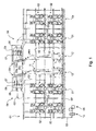
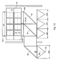
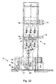
- Rotary printing press in particular newspaper press, illustrated by way of example, has a left and a right section, each having at least two printing towers 01.
- the printing towers 01 have printing units 02, which z. B. at least three times wide, ie for the pressure of six axially next to each other arranged newspaper pages are executed.
- the printing units 02 are designed as satellite printing units 02.
- the advantageous embodiment of the printing units 02 as nine-cylinder satellite printing units 02 ensures a very good Passerhaltmaschine or a low fan-out.
- the printing units 02 can also be used as ten-cylinder satellite printing units 02 or, if appropriate, also as printing units that can be operated in rubber-against-rubber printing, such as, for. B.
- a superstructure 04 Downstream of the printing towers 01 or printing units 02 continuous web 03, here above the printing towers 01, a superstructure 04 is provided for each section, in which the web 03 or webs 03 cut on longitudinal cutting devices 06, sub-webs by means of turning devices 07 possibly offset and / or crashed, by means of in Fig. 1 only indicated register devices 08 are aligned in the longitudinal register to each other and can be performed one above the other.
- the superstructure 04 has at least one so-called harp 09 with a number of superimposed webs 03 or part webs 03a; 03b; 03c leading harp or caster rollers.
- the harp 09 determines the funnel inlet of the superimposed tracks 03 or part tracks 03a; 03b; 03c.
- This harp 09 experience the webs 03 and part tracks 03a; 03b; 03c a change in direction and are subsequently summarized either as a strand or as multiple strands and fed to at least one folding structure 11.
- two Falz admittedten 11 are arranged between the sections, which z. B. each have arranged on two different superposed planes folding former.
- the printing machine can also only a common, between the sections arranged folding structure 11, or only have a section and an associated folding structure 11.
- the respective folding structure 11 may be performed with only one level of formers.
- Each folder assembly 11 are associated with one or more folders 12.
- the printing unit 02 has several, in the example four, printing units 13, by means of which ink can be applied to the web 03 by an inking unit 14 via at least one cylinder 16 designed as a forme cylinder 16 ( Fig. 2 ).
- the printing unit 13 is designed as offset printing unit 13 for the wet offset and has, in addition to the inking unit 14, a dampening unit 20 and another cylinder 17 designed as a transfer cylinder 17.
- the transfer cylinder 17 forms a pressure point with an abutment-forming impression cylinder 18.
- the printing cylinder 18 is designed as a satellite cylinder 18, which forms at least one further transfer cylinder 17, at least one further printing unit 13 and in Druck-AnStellung another pressure points.
- the printing cylinder 18 could possibly be designed as a transfer cylinder in the formation of the printing units 13 as a double printing in rubber-to-rubber pressure.
- the same parts are given the same reference numerals, as far as they are not necessary for differentiation. However, a difference in the spatial position may exist and, in the case of the assignment of the same reference numbers, is generally disregarded.
- the inking unit 14 has, in an advantageous embodiment, an ink fountain 15 extending over six print pages. In another embodiment, three each color about two pages wide ink boxes 15 are arranged side by side in the axial direction.
- the dampening unit 20 is designed in an advantageous embodiment as allocate to the dampening 20.
- the length L16 of the usable bale of the forme cylinder 16 is in the first embodiment z. B. 1,850 to 2,400 mm, in particular 1,900 to 2,300 mm and is in the axial direction for receiving z. B. at least six juxtaposed standing printed pages, especially newspaper pages of different formats, eg. B. in broadsheet and a different format, dimensioned (see Fig. 3 Sections A to F). Among other things, it depends on the nature of the product to be produced, whether in each case only one pressure side or several pressure sides in the axial direction are arranged side by side on a printing plate 19.
- the forme cylinder 16 z. B a circumference between 980 and 1300 mm, in particular from 1000 to 1200 mm.
- the length L16 of the usable bale is in this case z. B. 1,950 up to 2,500, advantageously 1,950 to 2,400 mm, in particular 2,000 to 2,400 mm.
- the occupancy corresponds to the o. G. Execution.
- the transfer cylinder 17 also has a circumference z in the first embodiment. B. between 850 and 1,000 mm, in particular from 900 to 940 mm.
- the length L17 of the usable bale of the transfer cylinder 17 is in the first embodiment z. B. also 1,850 to 2,400 mm, in particular 1,900 to 2,300 mm.
- He is in the longitudinal direction next to each other with only three-page printing elevators 21, z. B. printing or blanket 21, occupied (sections ABC and EFG). They extend in the circumferential direction substantially to the full extent.
- the blankets 21 are, the Vibration behavior of the printing unit 13 in the case of operation favorably influencing in the circumferential direction, z. B. by 180 °, to each other ( Figure 3 ) arranged.
- the transfer cylinder 17 z. B a circumference between 980 and 1300 mm, in particular from 1000 to 1200 mm.
- the length L17 of the usable bale is in this case z. B. 1,950 up to 2,500, advantageously 1,950 to 2,400 mm, in particular 2,000 to 2,400 mm.
- the occupancy of elevators 21 corresponds to the first embodiment.
- Diameter of bales of cylinders 16; 17 are in the first o. G. Execution z. B. from 270 to 320 mm, in particular from about 285 to 300 mm. In the second o. G. Execution is the diameter of bales of the cylinder 16; 17 z. B. from about 310 to 410 mm, in particular from 320 to about 380 mm. A ratio of a length of the usable bale of the cylinders 16; 17 to the diameter should be 5.8 to 8.8, z. B. at 6.3 to 8.0, in a wide version, especially at 6.5 to 8.0.
- the satellite cylinder 18 also substantially the dimensions and ratios, at least the associated transfer cylinder 17, on.
- the printing machine is as already mentioned above for the production of various product formats, i. H. the printing of webs 03 of different widths designed. By this is meant not a different width due to part-wide webs, as would be the case with "half", “third”, “two-thirds” webs of the same basic web. With the different web width, a different product format is associated with the same number of possible pages.
- Forming and transfer cylinder 16; 17 have in a particularly advantageous embodiment, the in Fig. 3 illustrated occupancy with the elevators 19; 21 on.
- Fig. 4 For this purpose, a particularly advantageous arrangement of channels 27; 36; 37 for attachment of the elevators 19; 21 shown.
- On the forme cylinder 16 two over the effective length of the forme cylinder 16 each continuous, spaced by 180 ° from each other in the circumferential direction channels 27 and channel openings 28 (openings 28) and the transfer cylinder 17 two in each case over half the effective length, by 180 ° to each other in the circumferential direction offset channels 36; 37 or channel openings 38; 39 (openings 38, 39).
- the channels 27; 36; 37 are in Fig. 4 merely slot-shaped shown for insertion of elevator ends, however, can inside, as explained in more detail below, open to receive a corresponding clamping and / or clamping device.
- a page number of newspaper pages viewed in the axial direction is z.
- B. in the first mode (newspaper printing, F1) and the second mode (newspaper printing, F2) is the same. It is preferably six pages of the corresponding format F1; F2.
- the larger width b1 is suitable for printing six juxtaposed newspaper pages in the first format F1 and is z. B. at 1,800 to 2,500, advantageously at 1,900 to 2,400 mm, in particular at 1,900 to 2,200 mm.
- the smaller width b2 is suitable for printing six juxtaposed newspaper pages in the second format F2 and is z. B. at 1,750 to 2,100, advantageously at 1,750 to 2,050 mm, preferably between 1,850 mm and 1,950 mm, but where b1> b2.
- the possible widths for the newspaper printing are not to be applied to the two mentioned, but for any arbitrary intermediate widths or formats. Ie. In principle, therefore, all tracks 03 of different widths (or corresponding newspaper formats) can be varied, which z. B. from 1,750 mm to 2,400 mm, at least from 1,850 and 2,200 mm.
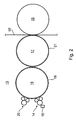
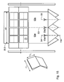
- Fig. 5 schematically shows the situation for a wide web 03.1 ( Fig. 5a ) and a narrow web 03.2 ( Fig. 5b ), wherein the main section lines S1 and S2 for the two different product widths (web widths) are shown.
- the term "main cutting lines” is understood here to mean the longitudinal sections which guide the web 03 in alignment between two adjacent formers 41; 42; 43 separates, so that the resulting partial webs only on the adjacent formers 41; 42; 43 become feasible.
- F41; F42; F43 designated folding planes which the symmetry planes of the respective former 41; 42; 43 represent and in which, if trained accordingly, the funnel tips.
- a distance A1 between the folding planes F41 and F42 and a distance A2 between the folding planes F42 and F43, depending on the width b1; b2 of the track 03.1; 03.2 and / or the current print page format F1; F2 and / or the type of assignment with printed images (symmetrical / asymmetrical) varies.
- these varying distances A1; A2 by movement of the outer formers 41; 43 achieved, wherein the middle former 42 remains stationary.
- Secondary cutting lines S4; S5 could, for example, in addition to the above-mentioned main section lines S1; S2 in the folding plane F41, the folding plane F42 and / or the folding plane F43 be provided, in which case in the case of the sidecut no longitudinally folded, but cut open at the back, loosely superimposed multilayer product is formed (see tabloid production Fig. 13 to 16 as well as special format with Pflugpfalz Fig. 17 and 18 ).
- the transfer cylinder 17 is equipped in the axial direction side by side with two three-page printing elevators 21 of the larger format.
- these two elevators 21 may each extend around the full circumference and may either be aligned with their ends (joints in the channel openings 38, 39) or be offset by 180 ° in the circumferential direction relative to one another (see above).
- two elevators 21 can be arranged one behind the other in the circumferential direction, in which case the ends of the two side by side arranged three-sided elevators 21 are aligned with each other. It is advantageous in any case if the two elevators 21 arranged axially next to each other together at least extend over the length of the transfer cylinder 17, which is required for printing the wider web 03.1.
- Fig. 6 shows the occupancy of the forme cylinder 16 with printing plates 19; 19 'in the mode in which it has printed images of the larger printed page format F1.
- the web width corresponds to the larger width b1.
- all (here twelve) 19 designed as a single printing forms 19 printing forms can be arranged.
- combinations of individual printing plates 19 and panorama printing plates 19 '(by way of example at the bottom right in FIG Fig. 6 shown) rest.
- the latter have a width of several -. B. two or even three - individual printing on 19 and wear either a Jatigallonsieribreites print image (panorama print page) or more each one or more pages wide print images of the first (larger) print page format F1.
- a panorama print form 19'(19") can have individual or panoramic print images in this sense.
- the distances A1 and A2 in Fig. 6 in each case twice the width b19 of a single printing form 19 or twice the printing page width bF1 of the larger format F1 or the width b19 'of a panorama printing form 19' or printing image of the larger format F1.
- Fig. 7 with twice the circumference (ie two newspaper pages on the circumference) with four, two on the circumference side by side and two consecutively, such three print images of the smaller printed page format F2 juxtaposed printing plates 19 "equipped For form cylinder 16 with single circumference would be only two such printing plates 19" provided side by side.
- the printing forms 19 each have a printed image of several pages in width and an impression-side printed image, but mixed variants are also possible, although not shown here:
- the distances A1 and A2 in Fig. 7 and 8th each correspond to twice the width of a potential, not shown single-page printing form or twice the printing page width bF2 of the smaller size F2.
- At least in one of the three formers 41 to 43 falls the folding plane F41; F42; F43 (here F42; F43) does not coincide with the center of the associated partial web 03a; 03b; 03c (here 03b and 03c) together, so that the resulting longitudinally folded sub-strand has unequal leg lengths.
- Fig. 12 shows one too Fig. 11 comparable representation, wherein in addition to the three formers 41 to 43, a further former 34 - in particular laterally to the other three - is arranged. About this is in so-called.
- "4-hopper production” at least one cut partial web 03a to 03c turned out of the straight line, passed over this fourth former 44 and finally fed to the folding apparatus 12 in addition to the other strands.
- the four formers 41 to 44 each have a total usable leg length, which corresponds to at least one sixth of the width b1 of the wider (or widest) web 03.1 (b1 / 6).
- the printing machine is in an operating mode for the printing of six juxtaposed standing printed pages of a newspaper format F1; F2 formed format F1; F2 (on a correspondingly wide web 03.1, 03.2) and in other operating mode for the printing of four juxtaposed lying printed pages operated as a tabloid format F3 format F3 operated or operable.
- This is in the Fig. 13 and 14 a first and in the Fig. 15 and 16 given a second embodiment.
- the forme cylinder 16 is again equipped with only two panoramic printing plates 19 ", which, however, carry printed images of a tabloid format F3 (not a newspaper format)
- the printed images lie with their later product length (after transverse fold) in the axial direction of the forme cylinder 16 and correspond to a quarter of the width b3 of the web 03.3 (b3 / 4) (see Fig. 14 ).
- the product width results after completed, not shown transverse fold substantially to a quarter of the circumference U FZ of the forme cylinder (U FZ / 4).
- the width b3 is z. B. smaller than the other two widths b1; b2 and is z. B.
- both partial webs 03a; 03b are each turned over a turning bar 46 by 90 ° from the previous transport direction to a longitudinal side of the printing machine and out of alignment three formers 41 to 43 out, whereupon they either transverse to the printing machine center axis M via a correspondingly oriented formers 44 or - like shown - after another Diverting at a further turning bar 46 by 90 ° via the correspondingly oriented former 42 to the folding apparatus 12 are supplied.
- the group of formers 41 to 43 having a width b1 or b2 of the original web 03.1; 03.2 produced while in another mode of operation in tabloid production on the former 42 and on the group of formers 44 with a width b3 of the original web 03.3 is produced.
- the width of the former 34 and the width b3 above applies.
- Fig. 17 and 18 show two other variants and modes of operation of the printing press, wherein by means of a web 03, z. B. the wider web 03.1, products in a special format with Pflugfalz - especially as a result in a tabloid format - can be produced.
- the forme cylinder 16 is again equipped with the over the entire length reaching printing plates 19 ", which in the frontal area each have a narrow print image (format F6) and in the middle area accordingly Fig. 13 or 15 Print images in a tabloid format, eg. B. the above-mentioned format F3, with their orientation.
- the two partial webs 03a already folded in the edge region; 03b are now either in the nature of the partial webs 03a and 03b Fig. 13 on a common Rajfalztrichter 44 (not shown) or as shown ( Fig. 17 ) straight ahead on the group of two vinfalztrichtern 44 out.
- Fig. 18 represents a further variant with regard to the versatile use of the printing press, wherein the forme cylinder 16 is again occupied by the two panorama printing forms 19 "over the full length but not here in the printing machine center axis M but asymmetrical to the forme cylinder 16 and the printed web 03.1.
- On the one side of the forme cylinder 16 for example, there is an occupancy from outside to inside with two sides in tabloid format F3 and one side in narrower format F6.
- the respective former 42 is designed to be movable transversely to the web running direction and positioned so that this part of the web 03a is straight on him feasible.
- the remaining partial web 03b also contains the narrow printed images (format F6) of the left-hand printing plates 19" and experiences a plow fold at least on the joint of the two elevators 21 of the transfer cylinder 17. especially straight ahead - is led.
- the second partial web 03b preferably also receives a plow fold in the outer region.
- the forme cylinder 16 may be juxtaposed in the axial direction two over two newspaper page widths of the currently relevant format F1; F2-reaching printing forms 19 '; 19 "wear.
- the form cylinder 16 has in the illustrated embodiment a circumference of two consecutively arranged printed pages of the larger newspaper format F1 and is in the circumferential direction one behind the other with two printing plates 19; 19 '; 19 "are arranged on the forme cylinder 16 preferably in through-channel openings 28.
- the printing plates 19; 19 '; 19 “then in two circumferentially offset from one another by 180 °, arranged in the axial direction through channel openings 28 and channels 27.
- the width b21 of the blankets 21 corresponds to z. B. in both modes of said number - here three - the printed pages of the larger format F1.
- the two blankets 21 are, for. B. as in Fig. 4 shown with their ends z. B. in the two mutually in the circumferential direction, in particular by 180 °, offset channel openings 38; 39 attached to the circumference of the transfer cylinder 17.
- the two channel openings 38; 39 rich in the illustrated embodiment each substantially across the width of a blanket 21 and not over the entire length of the transfer cylinder 17th
- the two channel openings 38 each extend over a pair of blankets 21 corresponding width.
- the width b21 of the triple-width blanket 21 is e.g. at 900 to 1250 mm, in particular 950 to 1200 mm, preferably between 1000 mm and 1100 mm.
- the channel opening 28 and 38; 39 for receiving the printing form ends and / or the blanket end in the region of the lateral surface preferably has a width in the circumferential direction of at most 5 mm, in particular of at most 3 mm.
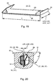
- a leading end 24 is, for example, at an acute angle ⁇ of 40 ° to 50 °, in particular 45 °, and a trailing end 26 at an angle ⁇ of 80 ° to 100 °, in particular 90 °, folded.
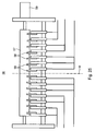
- two channels 27 are provided in the forme cylinder 16, wherein both channels 27 extend continuously in the axial direction of the cylinder 16 at least over the entire length of the six sections A to F in the bale (see Fig. 3 ). They are in the circumferential direction of the cylinder 16 z. B. offset by 180 ° to each other. Below a lateral surface 30 in the interior of the cylinder 16; (17) arranged, z. B. as in Fig. 20 shown as circular holes running channels 27; (36; 37) have a narrow slot-shaped opening 28 at least over the length of the six sections A to F; (38, 39) to the lateral surface 30 of the cylinder 16; (17).
- One slot width s28; (s38; s39) the opening 28; (38; 39) on the forme cylinder 16; (17) in the circumferential direction is less than 5 mm and is preferably in the range of 1 mm to 3 mm.
- the folded ends 24; 26 of the printing form 19; 21 are now each in one of the circumferentially axially parallel openings 28, (38, 39) can be inserted and are, at least the trailing end 26, by a in the channel 27; (36, 37) arranged holding device 29, 31 fixed.
- the holding device 29, 31 here has at least one clamping piece 29, z. B. clamping element 29 and a spring element 31 ( Fig. 20 ).
- the not shown right angle beveled trailing suspension legs 26 (see Fig. 19 ) preferably arrives at a wall of the opening 28 that is substantially complementary to the fold; (38, 39) to the plant and is there pressed by the clamping piece 29 by a force exerted by the spring element 31 on the clamping piece 29 force.
- the acute angle beveled leading suspension leg 24, not shown, (see Fig.
- a clamping piece 29 is in each channel 27 of the forme cylinder 16, but a plurality of clamping pieces 29 are arranged in the manner of segments with at least one spring element 31 axially adjacent to each other over the length of the sections A to F.
- each section A to F several, z. B. six, such clamping pieces 29, wherein centrally between the clamping elements 29 of each section A to F, here between the third and the fourth clamping element 29 of each section A to F, in each case a one exhibiting can be arranged.
- the register stone or Passer can also be shown in an unillustrated development via axially in a freely remaining cavity of the channel 27 and the fitting element guided actuator, for. B. a motor-driven threaded spindle, be axially movable.
- 17 advantageous embodiment is at least two cylinders 16; 17, in particular two forme cylinders 16, at least one of the printing towers 01 in each case a device for pressing an elevator 19; 21 to a cylinder 16; 17, in particular a printing forme 19 associated with the forme cylinder 16 (hereinafter pressing device).
- pressing device a device for pressing an elevator 19; 21 to a cylinder 16; 17, in particular a printing forme 19 associated with the forme cylinder 16 (hereinafter pressing device).
- pressing device z. B. advantageous if in two corresponding printing units 13 a faster, z. B. flying plate change to be made.
- a corresponding pressing device has z. B. at least six pressing elements, for. B.
- the pressing device extends along the cylinder 16; 17 at least in the entire range of sections A to F, d. H. in the effective for printing area of the bale. It can thus be fixed on the lateral surface 30 of the cylinder 16 elevators 19 by at least one pressure element as needed, while one end 24; 26 of an elevator 19 or more elevators 19 is released, d. H. at this time is not pressed or are.
- the cylinder 16; 17; 18 of the printing unit 02 driven so that the printing units 13 of the printing unit 02 are each rotationally driven at least by one of the other printing units 13 mechanically independent drive motor both in setup and in production.
- the satellite cylinder or cylinders 18 are likewise rotationally drivable by a drive motor, independently of the associated printing units 13.
- These drive motors are preferably as regulated with respect to their angular position electric motors, for. B. as induction motors, synchronous motors or DC motors.
- In an advantageous embodiment is between the respective drive motor and the driven cylinder 16; 17; 18 or cylinder pair 16, 17; 18, 18 arranged at least one gear, in particular at least one reduction gear (such as pinion, front and / or planetary gear).
- the spray source 49 may advantageously be designed as a spray bar 49 with spray nozzles or as a brush roller 49. In principle, however, other embodiments of the spray source are conceivable.
- the middle former 42 may be arranged fixed to the frame, wherein the funnel tip is preferably in the printing press center axis M.
- the formers 41; 42; 43 of this group transversely to the direction of incoming webs or partial webs 03a; 03b; 03c offset from each other next to each other and are viewed in a horizontal plane at least partially overlapping.
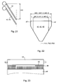
- a first structural variant (schematically in Fig. 21 ) are the two outer formers 41; 43 offset slightly in the vertical direction to the middle, in viewed horizontally, however, arranged with the middle former 42 intersecting, so that if necessary (narrow web 03.2 and corresponding narrow sub-webs 03a; 03b; 03c) seen in its middle the former 42 near the edge region in plan view in plan view can be brought into overlap with the latter.
- the funnel lugs are in vertical alignment with each other (shown in phantom), so that folded strands come to rest on each other.
- the vertical offset is a maximum of half a funnel height h42.
- a second variant (schematically in FIG Fig. 22 ) have the former 41; 42;
- movable (eg fold-away) or removable attachment elements 47 are removed.
- the extensions 47 thus widen the transport plane of the respective former 41; 42; 43, ie the plane which is formed by the contact zones of the converging flanks with the web 03.
- at least the middle of the former 42 has a width b42.1, while in the second operating position it has a width b42.2.
- the effective width is then made narrower by a total amount ⁇ .
- the two outer formers 41; 43 can also be designed to be reducible only on the side facing the middle former 42 by the amount .DELTA. / 2.
- Fig. 13 is exemplary the broad b41; b42; b43 of the former 41; 42; 43 of the group without general and without the addition shown.
- the fixed width designed for a fixed-format newspaper print, or width B42.1, which is not reduced in the case of variable newspaper printing, of at least the middle, but if appropriate, of all three former 41; 42; 43, z. B. at 600 to 830 mm, advantageously 630 to 600 mm, in particular 630 to 730 mm.
- formers 41; 42; 43 of variable width is the width B42.2 at least the middle, but possibly all three former 41; 42; 43, z. B. at about 580 to about 700, advantageously at 580 to 680 mm, preferably between about 616 mm and 650 mm.
- variable former 41; 42; 43 is a selectable difference ⁇ , for example, between 100 and 250 mm, in particular 120 to 200 mm, the widths are selected from the above ranges of values corresponding to each other. For ⁇ / 2, half the measure applies accordingly.
- the effective width b44 (maximum width in the upper hopper area) of the additional hopper 44 is preferably significantly larger than that of the (non-reduced) formers 41; 42; 43 of the funnel group.
- the width should be z. B. a factor 1.05 to 1.4, in particular 1.1 to 1.3 greater than a fixed or the maximum width b41.1; b42.1; b43.1 of the former 41; 42; 43 of the funnel group.
- Both additional funnels 44 may be formed with a variable width b44, in which case the above-mentioned ratios relate to the maximum width b44 of the additional funnel 44.
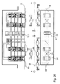
- a pull group 56 of tension roller 57 and a plurality of these can be selectively engageable pressure rollers 58, z. B. rubber rollers, be provided ( Fig. 25 ).
- These are symmetrical to the printing press central axis M in several (at least two) groups combined and connected in groups for the purpose of turning on or off.
- each half of the draw roller 57 from the outside in two groups of two and a group of three pressure rollers 58 are provided.
- the hiring takes place, for example, pneumatically from a source, not shown, or else electrically.
- the tension roller 57 is driven in rotation by a drive motor 59.
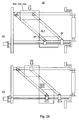
- a train group 61 -. B. following the last of the respective web 03 traversed printing unit 02 or before the hopper inlet - has these as pressure rollers 62 running guide and / or processing elements 62nd on which symmetrically and transversely to the printing machine center axis M are opposite to each other positionable ( Fig. 26a and b ).
- pressure rollers 62 running guide and / or processing elements 62nd on which symmetrically and transversely to the printing machine center axis M are opposite to each other positionable ( Fig. 26a and b ).
- an odd number of pressure rollers 62 is provided, wherein z. B. the middle in the alignment of the press center axis M effective and respect.
- a direction transverse to the transport direction is fixed, while all eccentric pressure rollers 62 are movable transversely to the transport direction and thus made adjustable to the web width.
- the longitudinal cutting device 06; 65 again preferably has an odd number of here as a knife 66 running guide and / or processing elements 66 which are symmetrical and transverse to the printing press center axis M in opposite directions to each other positionable.
- the central guide and / or processing element 66 is again effective in the alignment of the printing machine center axis M and fixedly arranged with respect to a direction transverse to the transport direction, while all eccentric knives 66 are movable transversely to the transport direction and thus made adjustable to the web width.
- the positioning is advantageous as in Fig. 26 the pressure roller 62. Together with the knives 66 counter knife 67 are preferably positioned with. While printing a wide web 03.1 ( Fig. 27a ) are provided outside the printing machine center axis M knives 66 more outward than during printing a narrower web 03.2; 03.3.
- the middle knife remains stationary in the alignment of the printing machine center axis M.
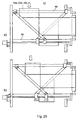
- a funnel structure 11 with fixed funnels 71 to 73 can be used, the fixed width of which is at least equal to the width of the sub-webs 03a, which arise from the widest web 03.1; 03b; 03c corresponds.
- FIG. 31 schematically shows the arrangement of two press sections each with several (here two) printing towers 01 and printing units 02, by means of which in each case one in Fig. 30a or b described, in Fig. 31 However, only schematically indicated turning device 07 is produced on a common hopper assembly 11.
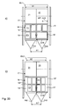
- Fig. 32 shows a folding structure 11 in section.
- two groups of substantially the same formers 41; 42; 43 may be arranged one above the other, which are either slightly vertically offset (not shown) or executed with lugs 47 (indicated only for the lower group).
- lugs 47 Indicated only for the lower group.
- a motor 74 hopper inlet roller 76 and pull roller 76 is provided.
- the folding apparatus 12 of the printing machine is designed for all the above embodiments in an advantageous embodiment seven-field.
- the circumference of the transport cylinder 77 corresponds to more than five, in particular seven section lengths or seven lengths of the signature ("siebenfeidriger transport cylinder 77").
- the holding devices can also be designed as a gripper (Greiferfalzapparat).
- seven cutting bars are arranged, which are preferably arranged in the direction of rotation slightly (eg 0.3 to 3 cm) to position of the nip (Greiferfalzapparat) or the puncture puncture (Punkturfalzapparat) spaced on the outer surface of the transport cylinder 77.
- the circumference of the jaw cylinder 78 preferably corresponds to more than five, in particular seven section lengths or seven lengths of the signature.
- the transport cylinder 77 On the transport cylinder 77 further seven folding blades are mounted, which are each extended upon reaching a gap (depending on collective or normal operation each or every multiple times) between the transport cylinder 77 and a jaw cylinder 78 to the transported on the transport cylinder 77 signatures on the jaw cylinder 78th to hand over and fold.
- the jaw cylinder 78 in the circumferential direction uniformly spaced z. B. as many jaws (not shown) on how the number of folding blades and / or the holding devices on the transport cylinder 77, in particular seven.
- the folded products are transferred from the jaw cylinder 78 to a paddle wheel 79 and from this to a delivery device 81, z. B. a conveyor belt 81 designed.
- An effective with the transport cylinder 77 as a cross-cutting device cutting cylinder 82 can double, d. H. two circumferentially spaced apart knives on the circumference, or four times large, d. H. four spaced by a section length blades on the circumference, be executed.
- the conception of the asymmetrically exposed panoramic printing plates, in particular together with at least one of a plurality of transversely movable formers 41; 42; 43 is in addition to the six pages wide machine (six print images side by side) on other machines, especially four pages wide newspaper presses (four print images side by side), applicable.
- n 3 printed images
- the four printed images can be arranged only on eight individual printing plates 19, only four panoramic printing plate 19 '(two adjacent and one after the other) or combined (example in FIG Fig. 33 combined).
- the printing plates 19; 19 ' preferably cover the entire effective length L16 and the width b1 of the printable larger train 03.1. If the printing unit 13 is not double-circumference (two newspaper pages in the circumferential direction) but simply executed, this applies equally to four individual printing plates 19 two panorama printing plates 19 'or mixed.
- the forme cylinder 16 now has printed images of the smaller format F2.
- the printing plates 19 are now again in the form of panoramic printing plates 19", but with two printed pages of the smaller format F 2, and nevertheless they again extend substantially over the range of the possible printing length of the wider web 03.1, d. H. they have the same width as panoramic printing plates 19 'of the larger format F1.
- the printing formations 19 are, for example, again asymmetrically exposed, as in the above-mentioned arrangement with three funnels, a funnel construction is also advantageous, wherein a distance A1 of the folding planes F42, F43 can be changed in the above-mentioned manner.
- the offset printing units 13 are at least one of the printing units 02 of a printing tower 11 (eg, however, of all printing units 02, 83 of a printing tower, but advantageously of all printing units 02, 83 of an entire printing press section, but especially of all printing units 02, 83 of the printing machine ) in the embodiment described above with three-page-wide printing plates 19 "and / or three-page-wide elevators 21 fitted or fitted formed.
- the folding structures 11 have z. B. at least one funnel plane, but advantageously two superimposed funnel planes with the three juxtaposed folding funnels 41 to 43 (eg Fig. 4 to 16 ) on.
- One or more of these Falzendedten 11 may advantageously additionally a side additional hopper 44 as from Fig. 12 to 14 (or possibly have an additional funnel layer with.
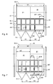
- Fig. 35 shows a printing machine in Parterrebauweise, ie reel changer 05 and printing towers 01; 01 a are at substantially the same level E, z. B. a ground floor level E arranged. This may provide advantages in terms of construction costs (no basement or lower height of a building 86 housing the printing towers 01, 01a, eg a hall 86). In an outside of the pressure towers 01; 01a and / or folding structure 11 lying area then the building 86 can be made significantly lower (indicated in in FIG Fig. 35 ).
- an additional folding hopper 44 can be arranged laterally to the group of the three formers in the folding structure 11 shown. This may be the case for one of the two or for both funnel planes drawn out, for example, if each of these again three formers 41; 42; 43 side by side.
- This additional hopper can be the same width as the other three formers, but how to Fig. 13 executed also have a greater width.
- Product strands eg so-called "books”
- books in the case of a larger funnel width of the additional funnel-optionally a product of greater width on the additional funnel Fig.
- FIG. 16 in the same way (one level three funnels, the other level two wider funnels).
- FIG. 32 may be a design wherein two "normal" hopper levels with three juxtaposed formers as in Fig. 32 are provided, and additionally twoificatfalztrichter 44 in an overlying level (indicated by dashed lines) in the manner of the two upper formers 44 from Fig. 16 arranged above it.
- One or more of the printing towers 01, as referred to here as 01 a, additional pressure units 83 have.
- the printing machine is also executed here in Parterrebauweise, ie reel changer 05 and printing towers 01; 01 a are arranged on substantially the same plane.
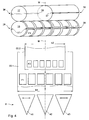
- the or the roll changer 05 is or stand laterally next to the machine, wherein the axis of rotation of the material or paper rolls runs substantially parallel to the printing machine center axis M. After unwinding across the machine, the web now runs at the height of the machine alignment on a deflecting element 84, z. B.
- the guide element 84 has a length which corresponds in projection to the incoming web at least its maximum width. It is preferably inclined by 45 ° to the running direction of the incoming web and to the machine center plane M. In the present case, it has a length whose projection on the incoming web corresponds to at least six adjacent newspaper pages.
- the usable length of the turning bar 84 corresponds at least 1.4 times the maximum web width to be processed in the printing press, ie in this case at least 1.4 times the width of a six-page wide web or in this case at least 8.5 newspaper page widths.
- two crossed turning bars can be provided, which then allow the deflection in one direction and in the other direction.
- the two crossed turner bars 84 can then either be acted on by a roll changer 05 with this web, or as shown, are acted upon by two in the same flight roll changer 05 simultaneously.
- the lateral arrangement of the roll changer 05 can again be considered on its own, but also develop particular advantage in conjunction with one or more advantageous features.
Landscapes
- Engineering & Computer Science (AREA)
- Mechanical Engineering (AREA)
- Folding Of Thin Sheet-Like Materials, Special Discharging Devices, And Others (AREA)
- Supply, Installation And Extraction Of Printed Sheets Or Plates (AREA)
Claims (27)
- Machine à imprimer rotative avec une unité d'impression (02) comportant un cylindre porte-plaque (16), ledit cylindre porte-plaque (16) étant pourvu d'une plaque d'impression (19") sur sa surface d'enveloppe, laquelle présente, disposées côte à côte dans la direction axiale du cylindre porte-plaque (16), des images d'impression d'un certain nombre de pages d'impression d'un format (F2) défini, caractérisée en ce qu'au moins dans un mode de service de l'unité d'impression (02) sur la plaque d'impression (19"), les images d'impression de n (pour n > 1) pages d'impression verticales au format journal (F2) sont disposées asymétriquement par rapport à un axe médian imaginaire (m19) de la plaque d'impression (19") qui s'étend sur la demi-largeur (b19") de la plaque d'impression (19") dans la direction longitudinale de celle-ci.
- Machine à imprimer rotative selon la revendication 1, caractérisée en ce que la plaque d'impression (19") présente une largeur qui correspond à une largeur du même nombre n d'images d'impression d'un format supérieur (F1).
- Machine à imprimer rotative selon la revendication 1 ou la revendication 2, caractérisée en ce que n est égal à 2.
- Machine à imprimer rotative selon la revendication 1 ou la revendication 2, caractérisée en ce que n est égal à 3.
- Machine à imprimer rotative selon la revendication 3 ou la revendication 4, caractérisée en ce que deux plaques d'impression (19") du type susmentionné sont disposées côte à côte dans la direction longitudinale sur le cylindre porte-plaque (16).
- Machine à imprimer rotative selon la revendication 3 ou la revendication 4, caractérisée en ce que deux plaques d'impression (19") du type susmentionné sont disposées successivement dans la direction périphérique sur le cylindre porte-plaque (16).
- Machine à imprimer rotative selon la revendication 3 ou la revendication 4, caractérisée en ce qu'une seule plaque d'impression (19") du type susmentionné est disposée dans la direction périphérique sur le cylindre porte-plaque (16).
- Machine à imprimer rotative selon l'une des revendications 1 à 7, caractérisée en ce que la plaque d'impression (19") est réalisée comme plaque d'impression plate pour une impression offset.
- Machine à imprimer rotative selon la revendication 2, caractérisée en ce que la longueur de la plaque d'impression (19") dans la direction périphérique correspond sensiblement à la longueur d'une page d'impression du grand format (F1).
- Machine à imprimer rotative selon la revendication 2, caractérisée en ce que le cylindre porte-plaque (16) présente dans la direction axiale une longueur (L16) correspondant à sensiblement six largeurs verticales de page de journal de grand format (F1), et en ce que la plaque d'impression (19") présente une largeur de trois pages d'impression, en particulier de grand format (F1).
- Machine à imprimer rotative selon la revendication 2, caractérisée en ce que le cylindre porte-plaque (16) présente dans la direction axiale une longueur (L16) correspondant à sensiblement quatre largeurs verticales de pages de journal de grand format (F1), et en ce que la plaque d'impression (19") présente une largeur de deux pages d'impression, en particulier de grand format (F1).
- Machine à imprimer rotative selon la revendication 10, caractérisée en ce que la plaque d'impression (19") large de trois pages d'impression présente une largeur de trois pages d'impression de grand format (F1) et est asymétriquement pourvue d'images d'impression d'un format inférieur (F2), en particulier asymétriquement insolée avec des images d'impression.
- Machine à imprimer rotative selon la revendication 11, caractérisée en ce que la plaque d'impression (19") large de deux pages d'impression présente une largeur de deux pages d'impression de grand format (F1) et est asymétriquement pourvue d'images d'impression d'un format inférieur (F2), en particulier asymétriquement insolée avec des images d'impression.
- Machine à imprimer rotative selon la revendication 12 ou la revendication 13, caractérisée en ce que les images d'impression sont disposées à équidistance sur la plaque d'impression (19") large de plusieurs pages, de manière à être disposées en succession directe d'un axe médian (M) de machine à imprimer vers l'extérieur et à laisser une zone sans impression dans la plage marginale proche du côté avant.
- Machine à imprimer rotative selon la revendication 14, caractérisée en ce que la plage marginale sans impression est comprise entre 50 et 100 mm.
- Machine à imprimer rotative selon les revendications 3 et 5, caractérisée en ce qu'une structure de pliage (11) avec deux cônes plieurs (41 ; 42) disposés côte à côte sur un plan de machine commun transversalement à la direction de transport de la bande est présentée en aval du groupe d'impression (13).
- Machine à imprimer rotative selon la revendication 16, caractérisée en ce qu'au moins un des cônes plieurs, et en particulier les deux cônes plieurs (41 ; 42) sont déplaçables transversalement à la direction de transport de la bande.
- Machine à imprimer rotative selon les revendications 4 et 5, caractérisée en ce qu'une structure de pliage (11) avec trois cônes plieurs (41 ; 42 ; 43) disposés côte à côte sur un plan de machine commun transversalement à la direction de transport de la bande est présentée en aval du groupe d'impression (13).
- Machine à imprimer rotative selon la revendication 18, caractérisée en ce qu'au moins les deux cônes extérieurs (41 ; 42) des trois cônes plieurs sont déplaçables transversalement à la direction de transport de la bande.
- Machine à imprimer rotative selon la revendication 1, caractérisée en ce que le groupe d'impression (13) comporte un cylindre de transfert (16 ; 17) coopérant avec le cylindre porte-plaque (16), lequel ne supporte que deux blanchets (21) disposés côte à côte sur sa périphérie dans la direction axiale.
- Machine à imprimer rotative selon la revendication 3, caractérisée en ce que le groupe d'impression (13) comporte un cylindre de transfert (16 ; 17) coopérant avec le cylindre porte-plaque (16), lequel ne supporte que deux blanchets (21) disposés côte à côte sur sa périphérie dans la direction axiale, et en ce que les blanchets (21) présentent chacun une largeur de deux pages de journal verticales de grand format (F1) dans la direction axiale.
- Machine à imprimer rotative selon la revendication 4, caractérisée en ce que le groupe d'impression (13) comporte un cylindre de transfert (16 ; 17) coopérant avec le cylindre porte-plaque (16), lequel ne supporte que deux blanchets (21) disposés côte à côte sur sa périphérie dans la direction axiale, et en ce que les blanchets (21) présentent chacun une largeur de trois pages de journal verticales de grand format (F1) dans la direction axiale.
- Machine à imprimer rotative selon la revendication 3 ou la revendication 4, caractérisée en ce que des extrémités (24 ; 26) contiguës de plaques d'impression (19") alignées axialement entre elles sur le cylindre porte-plaque (16) sont disposées dans une ouverture de canal (28) continue.
- Machine à imprimer rotative selon la revendication 6, caractérisée en ce que des extrémités (24 ; 26) contiguës de plaques d'impression (19") alignées axialement entre elles sur le cylindre porte-plaque (16) sont disposées dans une ouverture de canal (28) continue, et en ce que les plaques d'impression (19") sont disposées dans deux ouvertures de canal (28) continues dans la direction axiale, décalées de 180° l'une par rapport à l'autre dans la direction périphérique.
- Machine à imprimer rotative selon la revendication 1, caractérisée en ce que la plaque d'impression (19") présente une largeur (b19") comprise entre 950 et 1200 mm, en particulier entre 950 et 1100 mm.
- Machine à imprimer rotative selon la revendication 20, caractérisée en ce que le blanchet (21) présente une largeur (b21) comprise entre 950 et 1200 mm, en particulier entre 950 et 1100 mm.
- Machine à imprimer rotative selon la revendication 4, caractérisée en ce que la plaque d'impression (19") large de trois pages d'impression est gravée, en particulier insolée côte à côte avec une image d'impression correspondant à trois pages de journal ou avec plusieurs images d'impression correspondant ensemble à trois pages de journal.
Applications Claiming Priority (5)
| Application Number | Priority Date | Filing Date | Title |
|---|---|---|---|
| DE102004022231 | 2004-05-04 | ||
| DE102004030062 | 2004-06-23 | ||
| DE102004033920A DE102004033920B4 (de) | 2004-05-04 | 2004-07-14 | Druckform einer Druckmaschine und Rollenrotationsdruckmaschine |
| US63142104P | 2004-11-30 | 2004-11-30 | |
| EP05744815A EP1742794B1 (fr) | 2004-05-04 | 2005-04-29 | Presse rotative d'impression avec une unite d'impression comprenant un cylindre de plaques pour l'impression d'une triple largeur au moins |
Related Parent Applications (3)
| Application Number | Title | Priority Date | Filing Date |
|---|---|---|---|
| EP05744815.1 Division | 2005-04-29 | ||
| EP05744815A Division EP1742794B1 (fr) | 2004-05-04 | 2005-04-29 | Presse rotative d'impression avec une unite d'impression comprenant un cylindre de plaques pour l'impression d'une triple largeur au moins |
| EP05744815A Division-Into EP1742794B1 (fr) | 2004-05-04 | 2005-04-29 | Presse rotative d'impression avec une unite d'impression comprenant un cylindre de plaques pour l'impression d'une triple largeur au moins |
Publications (3)
| Publication Number | Publication Date |
|---|---|
| EP1908588A2 EP1908588A2 (fr) | 2008-04-09 |
| EP1908588A3 EP1908588A3 (fr) | 2011-05-25 |
| EP1908588B1 true EP1908588B1 (fr) | 2012-08-01 |
Family
ID=39079633
Family Applications (1)
| Application Number | Title | Priority Date | Filing Date |
|---|---|---|---|
| EP08150699A Expired - Lifetime EP1908588B1 (fr) | 2004-05-04 | 2005-04-29 | Machine d'impression rotative avec une unité d'impression comprenant un cylindre de plaques |
Country Status (1)
| Country | Link |
|---|---|
| EP (1) | EP1908588B1 (fr) |
Families Citing this family (4)
| Publication number | Priority date | Publication date | Assignee | Title |
|---|---|---|---|---|
| DE102008018840A1 (de) * | 2008-04-15 | 2009-10-22 | Manroland Ag | Vorrichtung zur Be- und/-oder Verarbeitung von bahnförmigem Material |
| CN103448352B (zh) * | 2008-05-28 | 2015-09-09 | 柯尼格及包尔公开股份有限公司 | 卷筒纸胶印机以及用于运行卷筒纸胶印机的方法 |
| DE102009027142B4 (de) * | 2009-06-24 | 2013-02-07 | Koenig & Bauer Aktiengesellschaft | Rollenrotationsdruckmaschine und Verfahren zur Steuerung der Rollenrotationsdruckmaschine |
| DE102010030267B4 (de) | 2010-06-18 | 2013-08-14 | Koenig & Bauer Aktiengesellschaft | Verfahren und Vorrichtung zur Steuerung einer Rollenrotationsdruckmaschine sowie Verfahren zum Betrieb einer Rollenrotationsdruckmaschine |
Family Cites Families (14)
| Publication number | Priority date | Publication date | Assignee | Title |
|---|---|---|---|---|
| DE2422696C2 (de) | 1974-05-10 | 1982-12-09 | M.A.N. Maschinenfabrik Augsburg-Nürnberg AG, 8900 Augsburg | Druckwerk für ein- oder beidseitigen Druck mit mindestens vier Zylindern |
| GB1476707A (en) | 1974-06-28 | 1977-06-16 | Rockwell International Corp | Printing plate arrangement |
| DE10016409B4 (de) | 1999-12-02 | 2007-03-15 | Koenig & Bauer Ag | Druckeinheit einer Rotationsdruckmaschine |
| US4671501A (en) | 1986-06-23 | 1987-06-09 | Kabushiki Kaisha Tokyo Kikai Seisakusho | Turning-bar-less folding machine of W-width rotary press |
| DE4128797C2 (de) | 1991-08-30 | 1994-01-27 | Koenig & Bauer Ag | Papierbahnführung in Rollenrotationsdruckmaschinen |
| DE4204254C2 (de) | 1992-02-13 | 1995-03-16 | Koenig & Bauer Ag | Einrichtung zum Längsfalzen mehrerer gleichbreiter Papierbahnen in einer Rollenrotationsdruckmaschine |
| US6024684A (en) | 1995-11-08 | 2000-02-15 | Koenig & Bauer Aktiengesellschaft | Device for producing folded items |
| DE19628647B4 (de) | 1996-07-16 | 2004-03-11 | Man Roland Druckmaschinen Ag | Farbtransportwalze für das Farbwerk einer Rollenrotationsdruckmaschine und Verfahren zur Herstellung der Walze |
| DE59802100D1 (de) * | 1997-12-16 | 2001-12-13 | Koenig & Bauer Ag | Druckprodukt und verfahren zur herstellung eines druckproduktes |
| DE19803809A1 (de) * | 1998-01-31 | 1999-08-05 | Roland Man Druckmasch | Offsetdruckwerk |
| US6152034A (en) | 1999-07-26 | 2000-11-28 | Heidelberger Druckmaschinen, Ag | Former board arrangement in a web-fed rotary newspaper printing press |
| EP1334825B1 (fr) * | 1999-12-02 | 2011-06-01 | Koenig & Bauer Aktiengesellschaft | Groupe d'impression d'une machine d'impression |
| DE10111112B4 (de) | 2001-03-08 | 2005-12-22 | Vaw Aluminium Ag | Untermesserwelle für eine Rollenschneidmaschine |
| US6868783B2 (en) * | 2001-09-07 | 2005-03-22 | Goss International Americas, Inc. | Printing press with multiple-image-carrying cylinder |
-
2005
- 2005-04-29 EP EP08150699A patent/EP1908588B1/fr not_active Expired - Lifetime
Also Published As
| Publication number | Publication date |
|---|---|
| EP1908588A3 (fr) | 2011-05-25 |
| EP1908588A2 (fr) | 2008-04-09 |
Similar Documents
| Publication | Publication Date | Title |
|---|---|---|
| EP1820645B1 (fr) | Presse rotative dotée d'un dispositif de pliage | |
| EP1466730B1 (fr) | Machine rotative d'impression à bobines | |
| EP1742794B1 (fr) | Presse rotative d'impression avec une unite d'impression comprenant un cylindre de plaques pour l'impression d'une triple largeur au moins | |
| EP1434694A1 (fr) | DISPOSITIF DE TRAITEMENT D UNE BANDE, ELEMENT DE PLIAG E D UNE PRESSE ROTATIVE A IMPRIMER ET PRESSE ROTATIVE A IMPR IMER | |
| EP1742793B1 (fr) | Groupe d'impression offset d'une imprimeuse destinee a l'impression de journaux | |
| EP1594698B1 (fr) | Rotative a bobines | |
| EP1908588B1 (fr) | Machine d'impression rotative avec une unité d'impression comprenant un cylindre de plaques | |
| EP1556217B1 (fr) | Presse a imprimer | |
| DE10318477A1 (de) | Rollenrotationsdruckmaschine | |
| EP1761384A1 (fr) | Machine rotative d´impression avec une barre de retournement | |
| DE10321989A1 (de) | Druckmaschine | |
| DE102004002984A1 (de) | Druckmaschine, Betriebsweise der Druckmaschine sowie Druckprodukte | |
| DE20220298U1 (de) | Falzaufbau einer Rollenrotationsdruckmaschine und Rollenrotationsdruckmaschine | |
| EP1598184A2 (fr) | Machine d'impression, mode opératoire de la presse ainsi que le produit obtenu par la presse | |
| DE20220296U1 (de) | Druckeinheit und eine Rotationsdruckmaschine | |
| DE202004021116U1 (de) | Druckmaschinen sowie Druckprodukte |
Legal Events
| Date | Code | Title | Description |
|---|---|---|---|
| PUAI | Public reference made under article 153(3) epc to a published international application that has entered the european phase |
Free format text: ORIGINAL CODE: 0009012 |
|
| AC | Divisional application: reference to earlier application |
Ref document number: 1742794 Country of ref document: EP Kind code of ref document: P |
|
| AK | Designated contracting states |
Kind code of ref document: A2 Designated state(s): AT BE BG CH CY CZ DE DK EE ES FI FR GB GR HU IE IS IT LI LT LU MC NL PL PT RO SE SI SK TR |
|
| AX | Request for extension of the european patent |
Extension state: AL BA HR LV MK YU |
|
| PUAL | Search report despatched |
Free format text: ORIGINAL CODE: 0009013 |
|
| AK | Designated contracting states |
Kind code of ref document: A3 Designated state(s): AT BE BG CH CY CZ DE DK EE ES FI FR GB GR HU IE IS IT LI LT LU MC NL PL PT RO SE SI SK TR |
|
| AX | Request for extension of the european patent |
Extension state: AL BA HR LV MK RS |
|
| 17P | Request for examination filed |
Effective date: 20110506 |
|
| AKX | Designation fees paid |
Designated state(s): AT BE BG CH CY CZ DE DK EE ES FI FR GB GR HU IE IS IT LI LT LU MC NL PL PT RO SE SI SK TR |
|
| REG | Reference to a national code |
Ref country code: DE Ref legal event code: R079 Ref document number: 502005012970 Country of ref document: DE Free format text: PREVIOUS MAIN CLASS: B41F0007100000 Ipc: B65H0045220000 |
|
| GRAP | Despatch of communication of intention to grant a patent |
Free format text: ORIGINAL CODE: EPIDOSNIGR1 |
|
| RIC1 | Information provided on ipc code assigned before grant |
Ipc: B41F 13/10 20060101ALI20120322BHEP Ipc: B65H 45/22 20060101AFI20120322BHEP Ipc: B41F 7/10 20060101ALI20120322BHEP |
|
| GRAS | Grant fee paid |
Free format text: ORIGINAL CODE: EPIDOSNIGR3 |
|
| GRAA | (expected) grant |
Free format text: ORIGINAL CODE: 0009210 |
|
| AC | Divisional application: reference to earlier application |
Ref document number: 1742794 Country of ref document: EP Kind code of ref document: P |
|
| AK | Designated contracting states |
Kind code of ref document: B1 Designated state(s): AT BE BG CH CY CZ DE DK EE ES FI FR GB GR HU IE IS IT LI LT LU MC NL PL PT RO SE SI SK TR |
|
| REG | Reference to a national code |
Ref country code: GB Ref legal event code: FG4D Free format text: NOT ENGLISH |
|
| REG | Reference to a national code |
Ref country code: AT Ref legal event code: REF Ref document number: 568563 Country of ref document: AT Kind code of ref document: T Effective date: 20120815 Ref country code: CH Ref legal event code: EP |
|
| REG | Reference to a national code |
Ref country code: IE Ref legal event code: FG4D Free format text: LANGUAGE OF EP DOCUMENT: GERMAN |
|
| REG | Reference to a national code |
Ref country code: DE Ref legal event code: R096 Ref document number: 502005012970 Country of ref document: DE Effective date: 20120927 |
|
| REG | Reference to a national code |
Ref country code: NL Ref legal event code: VDEP Effective date: 20120801 |
|
| REG | Reference to a national code |
Ref country code: LT Ref legal event code: MG4D Effective date: 20120801 |
|
| PG25 | Lapsed in a contracting state [announced via postgrant information from national office to epo] |
Ref country code: FI Free format text: LAPSE BECAUSE OF FAILURE TO SUBMIT A TRANSLATION OF THE DESCRIPTION OR TO PAY THE FEE WITHIN THE PRESCRIBED TIME-LIMIT Effective date: 20120801 Ref country code: LT Free format text: LAPSE BECAUSE OF FAILURE TO SUBMIT A TRANSLATION OF THE DESCRIPTION OR TO PAY THE FEE WITHIN THE PRESCRIBED TIME-LIMIT Effective date: 20120801 Ref country code: IS Free format text: LAPSE BECAUSE OF FAILURE TO SUBMIT A TRANSLATION OF THE DESCRIPTION OR TO PAY THE FEE WITHIN THE PRESCRIBED TIME-LIMIT Effective date: 20121201 Ref country code: CY Free format text: LAPSE BECAUSE OF FAILURE TO SUBMIT A TRANSLATION OF THE DESCRIPTION OR TO PAY THE FEE WITHIN THE PRESCRIBED TIME-LIMIT Effective date: 20120801 |
|
| PG25 | Lapsed in a contracting state [announced via postgrant information from national office to epo] |
Ref country code: SE Free format text: LAPSE BECAUSE OF FAILURE TO SUBMIT A TRANSLATION OF THE DESCRIPTION OR TO PAY THE FEE WITHIN THE PRESCRIBED TIME-LIMIT Effective date: 20120801 Ref country code: GR Free format text: LAPSE BECAUSE OF FAILURE TO SUBMIT A TRANSLATION OF THE DESCRIPTION OR TO PAY THE FEE WITHIN THE PRESCRIBED TIME-LIMIT Effective date: 20121102 Ref country code: SI Free format text: LAPSE BECAUSE OF FAILURE TO SUBMIT A TRANSLATION OF THE DESCRIPTION OR TO PAY THE FEE WITHIN THE PRESCRIBED TIME-LIMIT Effective date: 20120801 Ref country code: PT Free format text: LAPSE BECAUSE OF FAILURE TO SUBMIT A TRANSLATION OF THE DESCRIPTION OR TO PAY THE FEE WITHIN THE PRESCRIBED TIME-LIMIT Effective date: 20121203 Ref country code: PL Free format text: LAPSE BECAUSE OF FAILURE TO SUBMIT A TRANSLATION OF THE DESCRIPTION OR TO PAY THE FEE WITHIN THE PRESCRIBED TIME-LIMIT Effective date: 20120801 |
|
| PG25 | Lapsed in a contracting state [announced via postgrant information from national office to epo] |
Ref country code: NL Free format text: LAPSE BECAUSE OF FAILURE TO SUBMIT A TRANSLATION OF THE DESCRIPTION OR TO PAY THE FEE WITHIN THE PRESCRIBED TIME-LIMIT Effective date: 20120801 |
|
| PG25 | Lapsed in a contracting state [announced via postgrant information from national office to epo] |
Ref country code: DK Free format text: LAPSE BECAUSE OF FAILURE TO SUBMIT A TRANSLATION OF THE DESCRIPTION OR TO PAY THE FEE WITHIN THE PRESCRIBED TIME-LIMIT Effective date: 20120801 Ref country code: EE Free format text: LAPSE BECAUSE OF FAILURE TO SUBMIT A TRANSLATION OF THE DESCRIPTION OR TO PAY THE FEE WITHIN THE PRESCRIBED TIME-LIMIT Effective date: 20120801 Ref country code: RO Free format text: LAPSE BECAUSE OF FAILURE TO SUBMIT A TRANSLATION OF THE DESCRIPTION OR TO PAY THE FEE WITHIN THE PRESCRIBED TIME-LIMIT Effective date: 20120801 Ref country code: ES Free format text: LAPSE BECAUSE OF FAILURE TO SUBMIT A TRANSLATION OF THE DESCRIPTION OR TO PAY THE FEE WITHIN THE PRESCRIBED TIME-LIMIT Effective date: 20121112 Ref country code: CZ Free format text: LAPSE BECAUSE OF FAILURE TO SUBMIT A TRANSLATION OF THE DESCRIPTION OR TO PAY THE FEE WITHIN THE PRESCRIBED TIME-LIMIT Effective date: 20120801 |
|
| PG25 | Lapsed in a contracting state [announced via postgrant information from national office to epo] |
Ref country code: IT Free format text: LAPSE BECAUSE OF FAILURE TO SUBMIT A TRANSLATION OF THE DESCRIPTION OR TO PAY THE FEE WITHIN THE PRESCRIBED TIME-LIMIT Effective date: 20120801 Ref country code: SK Free format text: LAPSE BECAUSE OF FAILURE TO SUBMIT A TRANSLATION OF THE DESCRIPTION OR TO PAY THE FEE WITHIN THE PRESCRIBED TIME-LIMIT Effective date: 20120801 |
|
| PLBE | No opposition filed within time limit |
Free format text: ORIGINAL CODE: 0009261 |
|
| STAA | Information on the status of an ep patent application or granted ep patent |
Free format text: STATUS: NO OPPOSITION FILED WITHIN TIME LIMIT |
|
| 26N | No opposition filed |
Effective date: 20130503 |
|
| PG25 | Lapsed in a contracting state [announced via postgrant information from national office to epo] |
Ref country code: BG Free format text: LAPSE BECAUSE OF FAILURE TO SUBMIT A TRANSLATION OF THE DESCRIPTION OR TO PAY THE FEE WITHIN THE PRESCRIBED TIME-LIMIT Effective date: 20121101 |
|
| REG | Reference to a national code |
Ref country code: DE Ref legal event code: R097 Ref document number: 502005012970 Country of ref document: DE Effective date: 20130503 |
|
| BERE | Be: lapsed |
Owner name: KOENIG & BAUER A.G. Effective date: 20130430 |
|
| PG25 | Lapsed in a contracting state [announced via postgrant information from national office to epo] |
Ref country code: MC Free format text: LAPSE BECAUSE OF FAILURE TO SUBMIT A TRANSLATION OF THE DESCRIPTION OR TO PAY THE FEE WITHIN THE PRESCRIBED TIME-LIMIT Effective date: 20120801 |
|
| REG | Reference to a national code |
Ref country code: CH Ref legal event code: PL |
|
| REG | Reference to a national code |
Ref country code: IE Ref legal event code: MM4A |
|
| PG25 | Lapsed in a contracting state [announced via postgrant information from national office to epo] |
Ref country code: CH Free format text: LAPSE BECAUSE OF NON-PAYMENT OF DUE FEES Effective date: 20130430 Ref country code: BE Free format text: LAPSE BECAUSE OF NON-PAYMENT OF DUE FEES Effective date: 20130430 Ref country code: LI Free format text: LAPSE BECAUSE OF NON-PAYMENT OF DUE FEES Effective date: 20130430 |
|
| PG25 | Lapsed in a contracting state [announced via postgrant information from national office to epo] |
Ref country code: IE Free format text: LAPSE BECAUSE OF NON-PAYMENT OF DUE FEES Effective date: 20130429 |
|
| REG | Reference to a national code |
Ref country code: AT Ref legal event code: MM01 Ref document number: 568563 Country of ref document: AT Kind code of ref document: T Effective date: 20130429 |
|
| PG25 | Lapsed in a contracting state [announced via postgrant information from national office to epo] |
Ref country code: AT Free format text: LAPSE BECAUSE OF NON-PAYMENT OF DUE FEES Effective date: 20130429 |
|
| REG | Reference to a national code |
Ref country code: FR Ref legal event code: PLFP Year of fee payment: 11 |
|
| PG25 | Lapsed in a contracting state [announced via postgrant information from national office to epo] |
Ref country code: TR Free format text: LAPSE BECAUSE OF FAILURE TO SUBMIT A TRANSLATION OF THE DESCRIPTION OR TO PAY THE FEE WITHIN THE PRESCRIBED TIME-LIMIT Effective date: 20120801 |
|
| PG25 | Lapsed in a contracting state [announced via postgrant information from national office to epo] |
Ref country code: LU Free format text: LAPSE BECAUSE OF NON-PAYMENT OF DUE FEES Effective date: 20130429 Ref country code: HU Free format text: LAPSE BECAUSE OF FAILURE TO SUBMIT A TRANSLATION OF THE DESCRIPTION OR TO PAY THE FEE WITHIN THE PRESCRIBED TIME-LIMIT; INVALID AB INITIO Effective date: 20050429 |
|
| PGFP | Annual fee paid to national office [announced via postgrant information from national office to epo] |
Ref country code: GB Payment date: 20150424 Year of fee payment: 11 |
|
| PGFP | Annual fee paid to national office [announced via postgrant information from national office to epo] |
Ref country code: FR Payment date: 20150424 Year of fee payment: 11 |
|
| GBPC | Gb: european patent ceased through non-payment of renewal fee |
Effective date: 20160429 |
|
| REG | Reference to a national code |
Ref country code: FR Ref legal event code: ST Effective date: 20161230 |
|
| PG25 | Lapsed in a contracting state [announced via postgrant information from national office to epo] |
Ref country code: GB Free format text: LAPSE BECAUSE OF NON-PAYMENT OF DUE FEES Effective date: 20160429 Ref country code: FR Free format text: LAPSE BECAUSE OF NON-PAYMENT OF DUE FEES Effective date: 20160502 |
|
| PGFP | Annual fee paid to national office [announced via postgrant information from national office to epo] |
Ref country code: DE Payment date: 20180612 Year of fee payment: 14 |
|
| REG | Reference to a national code |
Ref country code: DE Ref legal event code: R119 Ref document number: 502005012970 Country of ref document: DE |
|
| PG25 | Lapsed in a contracting state [announced via postgrant information from national office to epo] |
Ref country code: DE Free format text: LAPSE BECAUSE OF NON-PAYMENT OF DUE FEES Effective date: 20191101 |