EP1908588B1 - Rotary printing machine with a printing unit having a plate cylinder - Google Patents
Rotary printing machine with a printing unit having a plate cylinder Download PDFInfo
- Publication number
- EP1908588B1 EP1908588B1 EP08150699A EP08150699A EP1908588B1 EP 1908588 B1 EP1908588 B1 EP 1908588B1 EP 08150699 A EP08150699 A EP 08150699A EP 08150699 A EP08150699 A EP 08150699A EP 1908588 B1 EP1908588 B1 EP 1908588B1
- Authority
- EP
- European Patent Office
- Prior art keywords
- printing
- machine according
- printing machine
- cylinder
- web
- Prior art date
- Legal status (The legal status is an assumption and is not a legal conclusion. Google has not performed a legal analysis and makes no representation as to the accuracy of the status listed.)
- Expired - Lifetime
Links
- 238000007639 printing Methods 0.000 title claims description 349
- 238000012546 transfer Methods 0.000 claims description 39
- 238000007645 offset printing Methods 0.000 claims description 7
- 238000004519 manufacturing process Methods 0.000 description 29
- 238000005520 cutting process Methods 0.000 description 25
- 238000012545 processing Methods 0.000 description 21
- WYWHKKSPHMUBEB-UHFFFAOYSA-N 6-Mercaptoguanine Natural products N1C(N)=NC(=S)C2=C1N=CN2 WYWHKKSPHMUBEB-UHFFFAOYSA-N 0.000 description 18
- 229940095374 tabloid Drugs 0.000 description 18
- 239000000463 material Substances 0.000 description 12
- 239000007921 spray Substances 0.000 description 10
- 230000008901 benefit Effects 0.000 description 7
- 238000003825 pressing Methods 0.000 description 7
- 238000013461 design Methods 0.000 description 6
- 238000010276 construction Methods 0.000 description 5
- 239000000725 suspension Substances 0.000 description 5
- 230000008859 change Effects 0.000 description 4
- 238000011161 development Methods 0.000 description 4
- 229910052751 metal Inorganic materials 0.000 description 4
- 239000002184 metal Substances 0.000 description 4
- 230000001154 acute effect Effects 0.000 description 3
- 238000012549 training Methods 0.000 description 3
- 238000007792 addition Methods 0.000 description 2
- 230000015572 biosynthetic process Effects 0.000 description 2
- 230000000295 complement effect Effects 0.000 description 2
- 238000006073 displacement reaction Methods 0.000 description 2
- 230000001747 exhibiting effect Effects 0.000 description 2
- 238000005755 formation reaction Methods 0.000 description 2
- 230000001737 promoting effect Effects 0.000 description 2
- 229910000838 Al alloy Inorganic materials 0.000 description 1
- 244000059549 Borneo rubber Species 0.000 description 1
- 206010070670 Limb asymmetry Diseases 0.000 description 1
- 238000005452 bending Methods 0.000 description 1
- 230000005540 biological transmission Effects 0.000 description 1
- 239000003086 colorant Substances 0.000 description 1
- 230000004069 differentiation Effects 0.000 description 1
- 238000010017 direct printing Methods 0.000 description 1
- 230000006698 induction Effects 0.000 description 1
- 238000003780 insertion Methods 0.000 description 1
- 230000037431 insertion Effects 0.000 description 1
- 238000003754 machining Methods 0.000 description 1
- 238000012423 maintenance Methods 0.000 description 1
- 230000007246 mechanism Effects 0.000 description 1
- 238000000034 method Methods 0.000 description 1
- 230000002093 peripheral effect Effects 0.000 description 1
- 230000009467 reduction Effects 0.000 description 1
- 230000001105 regulatory effect Effects 0.000 description 1
- 238000005096 rolling process Methods 0.000 description 1
- 239000004575 stone Substances 0.000 description 1
- 230000001360 synchronised effect Effects 0.000 description 1
- 238000005406 washing Methods 0.000 description 1
- 230000037303 wrinkles Effects 0.000 description 1
Images


Classifications
-
- B—PERFORMING OPERATIONS; TRANSPORTING
- B41—PRINTING; LINING MACHINES; TYPEWRITERS; STAMPS
- B41F—PRINTING MACHINES OR PRESSES
- B41F7/00—Rotary lithographic machines
- B41F7/02—Rotary lithographic machines for offset printing
- B41F7/10—Rotary lithographic machines for offset printing using one impression cylinder co-operating with several transfer cylinders for printing on sheets or webs, e.g. satellite-printing units
-
- B—PERFORMING OPERATIONS; TRANSPORTING
- B41—PRINTING; LINING MACHINES; TYPEWRITERS; STAMPS
- B41F—PRINTING MACHINES OR PRESSES
- B41F13/00—Common details of rotary presses or machines
- B41F13/08—Cylinders
- B41F13/10—Forme cylinders
-
- B—PERFORMING OPERATIONS; TRANSPORTING
- B65—CONVEYING; PACKING; STORING; HANDLING THIN OR FILAMENTARY MATERIAL
- B65H—HANDLING THIN OR FILAMENTARY MATERIAL, e.g. SHEETS, WEBS, CABLES
- B65H45/00—Folding thin material
- B65H45/12—Folding articles or webs with application of pressure to define or form crease lines
- B65H45/22—Longitudinal folders, i.e. for folding moving sheet material parallel to the direction of movement
- B65H45/221—Longitudinal folders, i.e. for folding moving sheet material parallel to the direction of movement incorporating folding triangles
- B65H45/225—Arrangements of folding triangles
Definitions
- the DE 25 28 008 A1 shows a printing machine for a direct printing method with form cylinders, which can be equipped in the axial direction with six and in the circumferential direction with two printing plates, and counterpressure cylinders, which are assignable in the axial direction three and in the circumferential direction with a pressure felt. Both the pressure plates arranged next to one another and the pressure felts arranged next to one another are offset relative to each other in the circumferential direction.
- a folding structure is known, according to which cut, transversely offset to each other part webs are fed to different formers.
- the horizontally juxtaposed former are z. T. vertically offset from each other.
- the EP 10 72 551 A2 shows a former arrangement with two groups of three formers, wherein the formers of a group lie in a plane and overlap in at least in the horizontal direction in its vertical extent.
- the invention has for its object to provide a web-fed rotary printing press with a printing cylinder having a forme cylinder.
- one or more devices of the guide and / or processing elements acting together with the web are variably adjustable to the different web width.
- These are, for example, pressure rollers in the intake train, catch rollers of a safety gear, blades of a longitudinal cutting device, pressure rollers of a train group and / or side by side arranged former of a folder structure.
- the web is advantageously symmetrical to the printing press center axis - ie, for example, centered to the cylinder width - passed through the machine.
- a mediator is arranged in said plane of symmetry. This can then in the transverse direction to Transport direction to be fixed, while the outer guide and / or processing elements to be movable transversely to the transport direction and thus should be made adjustable to the web width.
- the printing units are designed as nine-cylinder satellite printing units, which on the one hand has a high precision in the color register and on the other hand a low-vibration construction result.
- the training as a satellite printing unit is also advantageous because when the requirement for printing different web widths in rubber-to-rubber printing unit for at least one web width vorlägen direct contact zones without paper web. This would, as is well known, lead to greatly changed promotional behavior, which is currently the case. significant registry deviations and wrinkles can result.
- Vibrations are also reduced by the advantageous arrangement, design and mounting of lifts on the cylinders.
- openings on the lateral surfaces in the circumferential direction are minimized.
- the openings may be arranged alternately offset in the circumferential direction, that acts at least on a section length always a closed lateral surface with the forming or satellite cylinder together.
- the mechanically independent of the cylinder pairs drive the (or the) satellite cylinder has particular advantages in terms of the possibility of variable operation. For example, during production, a setup, z. As a flying printing form change or washing done. Conversely, a web can be retracted while other cylinders or pairs of cylinders are standing or undergoing a set-up program. Also, it is advantageous to operate in the presence of rubber blankets with positive or negative promotional properties, the satellite cylinder with a different surface speed of the other cylinders.
- Rotary printing press in particular newspaper press, illustrated by way of example, has a left and a right section, each having at least two printing towers 01.
- the printing towers 01 have printing units 02, which z. B. at least three times wide, ie for the pressure of six axially next to each other arranged newspaper pages are executed.
- the printing units 02 are designed as satellite printing units 02.
- the advantageous embodiment of the printing units 02 as nine-cylinder satellite printing units 02 ensures a very good Passerhaltmaschine or a low fan-out.
- the printing units 02 can also be used as ten-cylinder satellite printing units 02 or, if appropriate, also as printing units that can be operated in rubber-against-rubber printing, such as, for. B.
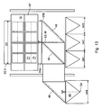
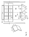
- a superstructure 04 Downstream of the printing towers 01 or printing units 02 continuous web 03, here above the printing towers 01, a superstructure 04 is provided for each section, in which the web 03 or webs 03 cut on longitudinal cutting devices 06, sub-webs by means of turning devices 07 possibly offset and / or crashed, by means of in Fig. 1 only indicated register devices 08 are aligned in the longitudinal register to each other and can be performed one above the other.
- the superstructure 04 has at least one so-called harp 09 with a number of superimposed webs 03 or part webs 03a; 03b; 03c leading harp or caster rollers.
- the harp 09 determines the funnel inlet of the superimposed tracks 03 or part tracks 03a; 03b; 03c.
- This harp 09 experience the webs 03 and part tracks 03a; 03b; 03c a change in direction and are subsequently summarized either as a strand or as multiple strands and fed to at least one folding structure 11.
- two Falz admittedten 11 are arranged between the sections, which z. B. each have arranged on two different superposed planes folding former.
- the printing machine can also only a common, between the sections arranged folding structure 11, or only have a section and an associated folding structure 11.
- the respective folding structure 11 may be performed with only one level of formers.
- Each folder assembly 11 are associated with one or more folders 12.
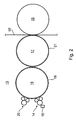
- the printing unit 02 has several, in the example four, printing units 13, by means of which ink can be applied to the web 03 by an inking unit 14 via at least one cylinder 16 designed as a forme cylinder 16 ( Fig. 2 ).
- the printing unit 13 is designed as offset printing unit 13 for the wet offset and has, in addition to the inking unit 14, a dampening unit 20 and another cylinder 17 designed as a transfer cylinder 17.
- the transfer cylinder 17 forms a pressure point with an abutment-forming impression cylinder 18.
- the printing cylinder 18 is designed as a satellite cylinder 18, which forms at least one further transfer cylinder 17, at least one further printing unit 13 and in Druck-AnStellung another pressure points.
- the printing cylinder 18 could possibly be designed as a transfer cylinder in the formation of the printing units 13 as a double printing in rubber-to-rubber pressure.
- the same parts are given the same reference numerals, as far as they are not necessary for differentiation. However, a difference in the spatial position may exist and, in the case of the assignment of the same reference numbers, is generally disregarded.
- the inking unit 14 has, in an advantageous embodiment, an ink fountain 15 extending over six print pages. In another embodiment, three each color about two pages wide ink boxes 15 are arranged side by side in the axial direction.
- the dampening unit 20 is designed in an advantageous embodiment as allocate to the dampening 20.
- the length L16 of the usable bale of the forme cylinder 16 is in the first embodiment z. B. 1,850 to 2,400 mm, in particular 1,900 to 2,300 mm and is in the axial direction for receiving z. B. at least six juxtaposed standing printed pages, especially newspaper pages of different formats, eg. B. in broadsheet and a different format, dimensioned (see Fig. 3 Sections A to F). Among other things, it depends on the nature of the product to be produced, whether in each case only one pressure side or several pressure sides in the axial direction are arranged side by side on a printing plate 19.
- the forme cylinder 16 z. B a circumference between 980 and 1300 mm, in particular from 1000 to 1200 mm.
- the length L16 of the usable bale is in this case z. B. 1,950 up to 2,500, advantageously 1,950 to 2,400 mm, in particular 2,000 to 2,400 mm.
- the occupancy corresponds to the o. G. Execution.
- the transfer cylinder 17 also has a circumference z in the first embodiment. B. between 850 and 1,000 mm, in particular from 900 to 940 mm.
- the length L17 of the usable bale of the transfer cylinder 17 is in the first embodiment z. B. also 1,850 to 2,400 mm, in particular 1,900 to 2,300 mm.
- He is in the longitudinal direction next to each other with only three-page printing elevators 21, z. B. printing or blanket 21, occupied (sections ABC and EFG). They extend in the circumferential direction substantially to the full extent.
- the blankets 21 are, the Vibration behavior of the printing unit 13 in the case of operation favorably influencing in the circumferential direction, z. B. by 180 °, to each other ( Figure 3 ) arranged.
- the transfer cylinder 17 z. B a circumference between 980 and 1300 mm, in particular from 1000 to 1200 mm.
- the length L17 of the usable bale is in this case z. B. 1,950 up to 2,500, advantageously 1,950 to 2,400 mm, in particular 2,000 to 2,400 mm.
- the occupancy of elevators 21 corresponds to the first embodiment.
- Diameter of bales of cylinders 16; 17 are in the first o. G. Execution z. B. from 270 to 320 mm, in particular from about 285 to 300 mm. In the second o. G. Execution is the diameter of bales of the cylinder 16; 17 z. B. from about 310 to 410 mm, in particular from 320 to about 380 mm. A ratio of a length of the usable bale of the cylinders 16; 17 to the diameter should be 5.8 to 8.8, z. B. at 6.3 to 8.0, in a wide version, especially at 6.5 to 8.0.
- the satellite cylinder 18 also substantially the dimensions and ratios, at least the associated transfer cylinder 17, on.
- the printing machine is as already mentioned above for the production of various product formats, i. H. the printing of webs 03 of different widths designed. By this is meant not a different width due to part-wide webs, as would be the case with "half", “third”, “two-thirds” webs of the same basic web. With the different web width, a different product format is associated with the same number of possible pages.
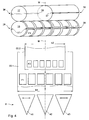
- Forming and transfer cylinder 16; 17 have in a particularly advantageous embodiment, the in Fig. 3 illustrated occupancy with the elevators 19; 21 on.
- Fig. 4 For this purpose, a particularly advantageous arrangement of channels 27; 36; 37 for attachment of the elevators 19; 21 shown.
- On the forme cylinder 16 two over the effective length of the forme cylinder 16 each continuous, spaced by 180 ° from each other in the circumferential direction channels 27 and channel openings 28 (openings 28) and the transfer cylinder 17 two in each case over half the effective length, by 180 ° to each other in the circumferential direction offset channels 36; 37 or channel openings 38; 39 (openings 38, 39).
- the channels 27; 36; 37 are in Fig. 4 merely slot-shaped shown for insertion of elevator ends, however, can inside, as explained in more detail below, open to receive a corresponding clamping and / or clamping device.
- a page number of newspaper pages viewed in the axial direction is z.
- B. in the first mode (newspaper printing, F1) and the second mode (newspaper printing, F2) is the same. It is preferably six pages of the corresponding format F1; F2.
- the larger width b1 is suitable for printing six juxtaposed newspaper pages in the first format F1 and is z. B. at 1,800 to 2,500, advantageously at 1,900 to 2,400 mm, in particular at 1,900 to 2,200 mm.
- the smaller width b2 is suitable for printing six juxtaposed newspaper pages in the second format F2 and is z. B. at 1,750 to 2,100, advantageously at 1,750 to 2,050 mm, preferably between 1,850 mm and 1,950 mm, but where b1> b2.
- the possible widths for the newspaper printing are not to be applied to the two mentioned, but for any arbitrary intermediate widths or formats. Ie. In principle, therefore, all tracks 03 of different widths (or corresponding newspaper formats) can be varied, which z. B. from 1,750 mm to 2,400 mm, at least from 1,850 and 2,200 mm.
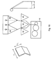
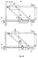
- Fig. 5 schematically shows the situation for a wide web 03.1 ( Fig. 5a ) and a narrow web 03.2 ( Fig. 5b ), wherein the main section lines S1 and S2 for the two different product widths (web widths) are shown.
- the term "main cutting lines” is understood here to mean the longitudinal sections which guide the web 03 in alignment between two adjacent formers 41; 42; 43 separates, so that the resulting partial webs only on the adjacent formers 41; 42; 43 become feasible.
- F41; F42; F43 designated folding planes which the symmetry planes of the respective former 41; 42; 43 represent and in which, if trained accordingly, the funnel tips.
- a distance A1 between the folding planes F41 and F42 and a distance A2 between the folding planes F42 and F43, depending on the width b1; b2 of the track 03.1; 03.2 and / or the current print page format F1; F2 and / or the type of assignment with printed images (symmetrical / asymmetrical) varies.
- these varying distances A1; A2 by movement of the outer formers 41; 43 achieved, wherein the middle former 42 remains stationary.
- Secondary cutting lines S4; S5 could, for example, in addition to the above-mentioned main section lines S1; S2 in the folding plane F41, the folding plane F42 and / or the folding plane F43 be provided, in which case in the case of the sidecut no longitudinally folded, but cut open at the back, loosely superimposed multilayer product is formed (see tabloid production Fig. 13 to 16 as well as special format with Pflugpfalz Fig. 17 and 18 ).
- the transfer cylinder 17 is equipped in the axial direction side by side with two three-page printing elevators 21 of the larger format.
- these two elevators 21 may each extend around the full circumference and may either be aligned with their ends (joints in the channel openings 38, 39) or be offset by 180 ° in the circumferential direction relative to one another (see above).
- two elevators 21 can be arranged one behind the other in the circumferential direction, in which case the ends of the two side by side arranged three-sided elevators 21 are aligned with each other. It is advantageous in any case if the two elevators 21 arranged axially next to each other together at least extend over the length of the transfer cylinder 17, which is required for printing the wider web 03.1.
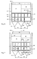
- Fig. 6 shows the occupancy of the forme cylinder 16 with printing plates 19; 19 'in the mode in which it has printed images of the larger printed page format F1.
- the web width corresponds to the larger width b1.
- all (here twelve) 19 designed as a single printing forms 19 printing forms can be arranged.
- combinations of individual printing plates 19 and panorama printing plates 19 '(by way of example at the bottom right in FIG Fig. 6 shown) rest.
- the latter have a width of several -. B. two or even three - individual printing on 19 and wear either a Jatigallonsieribreites print image (panorama print page) or more each one or more pages wide print images of the first (larger) print page format F1.
- a panorama print form 19'(19") can have individual or panoramic print images in this sense.
- the distances A1 and A2 in Fig. 6 in each case twice the width b19 of a single printing form 19 or twice the printing page width bF1 of the larger format F1 or the width b19 'of a panorama printing form 19' or printing image of the larger format F1.
- Fig. 7 with twice the circumference (ie two newspaper pages on the circumference) with four, two on the circumference side by side and two consecutively, such three print images of the smaller printed page format F2 juxtaposed printing plates 19 "equipped For form cylinder 16 with single circumference would be only two such printing plates 19" provided side by side.
- the printing forms 19 each have a printed image of several pages in width and an impression-side printed image, but mixed variants are also possible, although not shown here:
- the distances A1 and A2 in Fig. 7 and 8th each correspond to twice the width of a potential, not shown single-page printing form or twice the printing page width bF2 of the smaller size F2.
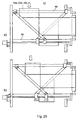
- At least in one of the three formers 41 to 43 falls the folding plane F41; F42; F43 (here F42; F43) does not coincide with the center of the associated partial web 03a; 03b; 03c (here 03b and 03c) together, so that the resulting longitudinally folded sub-strand has unequal leg lengths.
- Fig. 12 shows one too Fig. 11 comparable representation, wherein in addition to the three formers 41 to 43, a further former 34 - in particular laterally to the other three - is arranged. About this is in so-called.
- "4-hopper production” at least one cut partial web 03a to 03c turned out of the straight line, passed over this fourth former 44 and finally fed to the folding apparatus 12 in addition to the other strands.
- the four formers 41 to 44 each have a total usable leg length, which corresponds to at least one sixth of the width b1 of the wider (or widest) web 03.1 (b1 / 6).
- the printing machine is in an operating mode for the printing of six juxtaposed standing printed pages of a newspaper format F1; F2 formed format F1; F2 (on a correspondingly wide web 03.1, 03.2) and in other operating mode for the printing of four juxtaposed lying printed pages operated as a tabloid format F3 format F3 operated or operable.
- This is in the Fig. 13 and 14 a first and in the Fig. 15 and 16 given a second embodiment.
- the forme cylinder 16 is again equipped with only two panoramic printing plates 19 ", which, however, carry printed images of a tabloid format F3 (not a newspaper format)
- the printed images lie with their later product length (after transverse fold) in the axial direction of the forme cylinder 16 and correspond to a quarter of the width b3 of the web 03.3 (b3 / 4) (see Fig. 14 ).
- the product width results after completed, not shown transverse fold substantially to a quarter of the circumference U FZ of the forme cylinder (U FZ / 4).
- the width b3 is z. B. smaller than the other two widths b1; b2 and is z. B.
- both partial webs 03a; 03b are each turned over a turning bar 46 by 90 ° from the previous transport direction to a longitudinal side of the printing machine and out of alignment three formers 41 to 43 out, whereupon they either transverse to the printing machine center axis M via a correspondingly oriented formers 44 or - like shown - after another Diverting at a further turning bar 46 by 90 ° via the correspondingly oriented former 42 to the folding apparatus 12 are supplied.
- the group of formers 41 to 43 having a width b1 or b2 of the original web 03.1; 03.2 produced while in another mode of operation in tabloid production on the former 42 and on the group of formers 44 with a width b3 of the original web 03.3 is produced.
- the width of the former 34 and the width b3 above applies.
- Fig. 17 and 18 show two other variants and modes of operation of the printing press, wherein by means of a web 03, z. B. the wider web 03.1, products in a special format with Pflugfalz - especially as a result in a tabloid format - can be produced.
- the forme cylinder 16 is again equipped with the over the entire length reaching printing plates 19 ", which in the frontal area each have a narrow print image (format F6) and in the middle area accordingly Fig. 13 or 15 Print images in a tabloid format, eg. B. the above-mentioned format F3, with their orientation.
- the two partial webs 03a already folded in the edge region; 03b are now either in the nature of the partial webs 03a and 03b Fig. 13 on a common Rajfalztrichter 44 (not shown) or as shown ( Fig. 17 ) straight ahead on the group of two vinfalztrichtern 44 out.
- Fig. 18 represents a further variant with regard to the versatile use of the printing press, wherein the forme cylinder 16 is again occupied by the two panorama printing forms 19 "over the full length but not here in the printing machine center axis M but asymmetrical to the forme cylinder 16 and the printed web 03.1.
- On the one side of the forme cylinder 16 for example, there is an occupancy from outside to inside with two sides in tabloid format F3 and one side in narrower format F6.
- the respective former 42 is designed to be movable transversely to the web running direction and positioned so that this part of the web 03a is straight on him feasible.
- the remaining partial web 03b also contains the narrow printed images (format F6) of the left-hand printing plates 19" and experiences a plow fold at least on the joint of the two elevators 21 of the transfer cylinder 17. especially straight ahead - is led.
- the second partial web 03b preferably also receives a plow fold in the outer region.
- the forme cylinder 16 may be juxtaposed in the axial direction two over two newspaper page widths of the currently relevant format F1; F2-reaching printing forms 19 '; 19 "wear.
- the form cylinder 16 has in the illustrated embodiment a circumference of two consecutively arranged printed pages of the larger newspaper format F1 and is in the circumferential direction one behind the other with two printing plates 19; 19 '; 19 "are arranged on the forme cylinder 16 preferably in through-channel openings 28.
- the printing plates 19; 19 '; 19 “then in two circumferentially offset from one another by 180 °, arranged in the axial direction through channel openings 28 and channels 27.
- the width b21 of the blankets 21 corresponds to z. B. in both modes of said number - here three - the printed pages of the larger format F1.
- the two blankets 21 are, for. B. as in Fig. 4 shown with their ends z. B. in the two mutually in the circumferential direction, in particular by 180 °, offset channel openings 38; 39 attached to the circumference of the transfer cylinder 17.
- the two channel openings 38; 39 rich in the illustrated embodiment each substantially across the width of a blanket 21 and not over the entire length of the transfer cylinder 17th
- the two channel openings 38 each extend over a pair of blankets 21 corresponding width.
- the width b21 of the triple-width blanket 21 is e.g. at 900 to 1250 mm, in particular 950 to 1200 mm, preferably between 1000 mm and 1100 mm.
- the channel opening 28 and 38; 39 for receiving the printing form ends and / or the blanket end in the region of the lateral surface preferably has a width in the circumferential direction of at most 5 mm, in particular of at most 3 mm.
- a leading end 24 is, for example, at an acute angle ⁇ of 40 ° to 50 °, in particular 45 °, and a trailing end 26 at an angle ⁇ of 80 ° to 100 °, in particular 90 °, folded.
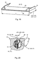
- two channels 27 are provided in the forme cylinder 16, wherein both channels 27 extend continuously in the axial direction of the cylinder 16 at least over the entire length of the six sections A to F in the bale (see Fig. 3 ). They are in the circumferential direction of the cylinder 16 z. B. offset by 180 ° to each other. Below a lateral surface 30 in the interior of the cylinder 16; (17) arranged, z. B. as in Fig. 20 shown as circular holes running channels 27; (36; 37) have a narrow slot-shaped opening 28 at least over the length of the six sections A to F; (38, 39) to the lateral surface 30 of the cylinder 16; (17).
- One slot width s28; (s38; s39) the opening 28; (38; 39) on the forme cylinder 16; (17) in the circumferential direction is less than 5 mm and is preferably in the range of 1 mm to 3 mm.
- the folded ends 24; 26 of the printing form 19; 21 are now each in one of the circumferentially axially parallel openings 28, (38, 39) can be inserted and are, at least the trailing end 26, by a in the channel 27; (36, 37) arranged holding device 29, 31 fixed.
- the holding device 29, 31 here has at least one clamping piece 29, z. B. clamping element 29 and a spring element 31 ( Fig. 20 ).
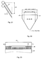
- the not shown right angle beveled trailing suspension legs 26 (see Fig. 19 ) preferably arrives at a wall of the opening 28 that is substantially complementary to the fold; (38, 39) to the plant and is there pressed by the clamping piece 29 by a force exerted by the spring element 31 on the clamping piece 29 force.
- the acute angle beveled leading suspension leg 24, not shown, (see Fig.
- a clamping piece 29 is in each channel 27 of the forme cylinder 16, but a plurality of clamping pieces 29 are arranged in the manner of segments with at least one spring element 31 axially adjacent to each other over the length of the sections A to F.
- each section A to F several, z. B. six, such clamping pieces 29, wherein centrally between the clamping elements 29 of each section A to F, here between the third and the fourth clamping element 29 of each section A to F, in each case a one exhibiting can be arranged.
- the register stone or Passer can also be shown in an unillustrated development via axially in a freely remaining cavity of the channel 27 and the fitting element guided actuator, for. B. a motor-driven threaded spindle, be axially movable.
- 17 advantageous embodiment is at least two cylinders 16; 17, in particular two forme cylinders 16, at least one of the printing towers 01 in each case a device for pressing an elevator 19; 21 to a cylinder 16; 17, in particular a printing forme 19 associated with the forme cylinder 16 (hereinafter pressing device).
- pressing device a device for pressing an elevator 19; 21 to a cylinder 16; 17, in particular a printing forme 19 associated with the forme cylinder 16 (hereinafter pressing device).
- pressing device z. B. advantageous if in two corresponding printing units 13 a faster, z. B. flying plate change to be made.
- a corresponding pressing device has z. B. at least six pressing elements, for. B.
- the pressing device extends along the cylinder 16; 17 at least in the entire range of sections A to F, d. H. in the effective for printing area of the bale. It can thus be fixed on the lateral surface 30 of the cylinder 16 elevators 19 by at least one pressure element as needed, while one end 24; 26 of an elevator 19 or more elevators 19 is released, d. H. at this time is not pressed or are.
- the cylinder 16; 17; 18 of the printing unit 02 driven so that the printing units 13 of the printing unit 02 are each rotationally driven at least by one of the other printing units 13 mechanically independent drive motor both in setup and in production.
- the satellite cylinder or cylinders 18 are likewise rotationally drivable by a drive motor, independently of the associated printing units 13.
- These drive motors are preferably as regulated with respect to their angular position electric motors, for. B. as induction motors, synchronous motors or DC motors.
- In an advantageous embodiment is between the respective drive motor and the driven cylinder 16; 17; 18 or cylinder pair 16, 17; 18, 18 arranged at least one gear, in particular at least one reduction gear (such as pinion, front and / or planetary gear).
- the spray source 49 may advantageously be designed as a spray bar 49 with spray nozzles or as a brush roller 49. In principle, however, other embodiments of the spray source are conceivable.
- the middle former 42 may be arranged fixed to the frame, wherein the funnel tip is preferably in the printing press center axis M.
- the formers 41; 42; 43 of this group transversely to the direction of incoming webs or partial webs 03a; 03b; 03c offset from each other next to each other and are viewed in a horizontal plane at least partially overlapping.
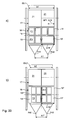
- a first structural variant (schematically in Fig. 21 ) are the two outer formers 41; 43 offset slightly in the vertical direction to the middle, in viewed horizontally, however, arranged with the middle former 42 intersecting, so that if necessary (narrow web 03.2 and corresponding narrow sub-webs 03a; 03b; 03c) seen in its middle the former 42 near the edge region in plan view in plan view can be brought into overlap with the latter.
- the funnel lugs are in vertical alignment with each other (shown in phantom), so that folded strands come to rest on each other.
- the vertical offset is a maximum of half a funnel height h42.
- a second variant (schematically in FIG Fig. 22 ) have the former 41; 42;
- movable (eg fold-away) or removable attachment elements 47 are removed.
- the extensions 47 thus widen the transport plane of the respective former 41; 42; 43, ie the plane which is formed by the contact zones of the converging flanks with the web 03.
- at least the middle of the former 42 has a width b42.1, while in the second operating position it has a width b42.2.
- the effective width is then made narrower by a total amount ⁇ .
- the two outer formers 41; 43 can also be designed to be reducible only on the side facing the middle former 42 by the amount .DELTA. / 2.
- Fig. 13 is exemplary the broad b41; b42; b43 of the former 41; 42; 43 of the group without general and without the addition shown.
- the fixed width designed for a fixed-format newspaper print, or width B42.1, which is not reduced in the case of variable newspaper printing, of at least the middle, but if appropriate, of all three former 41; 42; 43, z. B. at 600 to 830 mm, advantageously 630 to 600 mm, in particular 630 to 730 mm.
- formers 41; 42; 43 of variable width is the width B42.2 at least the middle, but possibly all three former 41; 42; 43, z. B. at about 580 to about 700, advantageously at 580 to 680 mm, preferably between about 616 mm and 650 mm.
- variable former 41; 42; 43 is a selectable difference ⁇ , for example, between 100 and 250 mm, in particular 120 to 200 mm, the widths are selected from the above ranges of values corresponding to each other. For ⁇ / 2, half the measure applies accordingly.
- the effective width b44 (maximum width in the upper hopper area) of the additional hopper 44 is preferably significantly larger than that of the (non-reduced) formers 41; 42; 43 of the funnel group.
- the width should be z. B. a factor 1.05 to 1.4, in particular 1.1 to 1.3 greater than a fixed or the maximum width b41.1; b42.1; b43.1 of the former 41; 42; 43 of the funnel group.
- Both additional funnels 44 may be formed with a variable width b44, in which case the above-mentioned ratios relate to the maximum width b44 of the additional funnel 44.
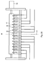
- a pull group 56 of tension roller 57 and a plurality of these can be selectively engageable pressure rollers 58, z. B. rubber rollers, be provided ( Fig. 25 ).
- These are symmetrical to the printing press central axis M in several (at least two) groups combined and connected in groups for the purpose of turning on or off.
- each half of the draw roller 57 from the outside in two groups of two and a group of three pressure rollers 58 are provided.
- the hiring takes place, for example, pneumatically from a source, not shown, or else electrically.
- the tension roller 57 is driven in rotation by a drive motor 59.
- a train group 61 -. B. following the last of the respective web 03 traversed printing unit 02 or before the hopper inlet - has these as pressure rollers 62 running guide and / or processing elements 62nd on which symmetrically and transversely to the printing machine center axis M are opposite to each other positionable ( Fig. 26a and b ).
- pressure rollers 62 running guide and / or processing elements 62nd on which symmetrically and transversely to the printing machine center axis M are opposite to each other positionable ( Fig. 26a and b ).
- an odd number of pressure rollers 62 is provided, wherein z. B. the middle in the alignment of the press center axis M effective and respect.
- a direction transverse to the transport direction is fixed, while all eccentric pressure rollers 62 are movable transversely to the transport direction and thus made adjustable to the web width.
- the longitudinal cutting device 06; 65 again preferably has an odd number of here as a knife 66 running guide and / or processing elements 66 which are symmetrical and transverse to the printing press center axis M in opposite directions to each other positionable.
- the central guide and / or processing element 66 is again effective in the alignment of the printing machine center axis M and fixedly arranged with respect to a direction transverse to the transport direction, while all eccentric knives 66 are movable transversely to the transport direction and thus made adjustable to the web width.
- the positioning is advantageous as in Fig. 26 the pressure roller 62. Together with the knives 66 counter knife 67 are preferably positioned with. While printing a wide web 03.1 ( Fig. 27a ) are provided outside the printing machine center axis M knives 66 more outward than during printing a narrower web 03.2; 03.3.
- the middle knife remains stationary in the alignment of the printing machine center axis M.
- a funnel structure 11 with fixed funnels 71 to 73 can be used, the fixed width of which is at least equal to the width of the sub-webs 03a, which arise from the widest web 03.1; 03b; 03c corresponds.
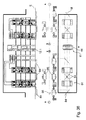
- FIG. 31 schematically shows the arrangement of two press sections each with several (here two) printing towers 01 and printing units 02, by means of which in each case one in Fig. 30a or b described, in Fig. 31 However, only schematically indicated turning device 07 is produced on a common hopper assembly 11.
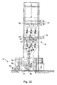
- Fig. 32 shows a folding structure 11 in section.
- two groups of substantially the same formers 41; 42; 43 may be arranged one above the other, which are either slightly vertically offset (not shown) or executed with lugs 47 (indicated only for the lower group).
- lugs 47 Indicated only for the lower group.
- a motor 74 hopper inlet roller 76 and pull roller 76 is provided.
- the folding apparatus 12 of the printing machine is designed for all the above embodiments in an advantageous embodiment seven-field.
- the circumference of the transport cylinder 77 corresponds to more than five, in particular seven section lengths or seven lengths of the signature ("siebenfeidriger transport cylinder 77").
- the holding devices can also be designed as a gripper (Greiferfalzapparat).
- seven cutting bars are arranged, which are preferably arranged in the direction of rotation slightly (eg 0.3 to 3 cm) to position of the nip (Greiferfalzapparat) or the puncture puncture (Punkturfalzapparat) spaced on the outer surface of the transport cylinder 77.
- the circumference of the jaw cylinder 78 preferably corresponds to more than five, in particular seven section lengths or seven lengths of the signature.
- the transport cylinder 77 On the transport cylinder 77 further seven folding blades are mounted, which are each extended upon reaching a gap (depending on collective or normal operation each or every multiple times) between the transport cylinder 77 and a jaw cylinder 78 to the transported on the transport cylinder 77 signatures on the jaw cylinder 78th to hand over and fold.
- the jaw cylinder 78 in the circumferential direction uniformly spaced z. B. as many jaws (not shown) on how the number of folding blades and / or the holding devices on the transport cylinder 77, in particular seven.
- the folded products are transferred from the jaw cylinder 78 to a paddle wheel 79 and from this to a delivery device 81, z. B. a conveyor belt 81 designed.
- An effective with the transport cylinder 77 as a cross-cutting device cutting cylinder 82 can double, d. H. two circumferentially spaced apart knives on the circumference, or four times large, d. H. four spaced by a section length blades on the circumference, be executed.
- the conception of the asymmetrically exposed panoramic printing plates, in particular together with at least one of a plurality of transversely movable formers 41; 42; 43 is in addition to the six pages wide machine (six print images side by side) on other machines, especially four pages wide newspaper presses (four print images side by side), applicable.
- n 3 printed images
- the four printed images can be arranged only on eight individual printing plates 19, only four panoramic printing plate 19 '(two adjacent and one after the other) or combined (example in FIG Fig. 33 combined).
- the printing plates 19; 19 ' preferably cover the entire effective length L16 and the width b1 of the printable larger train 03.1. If the printing unit 13 is not double-circumference (two newspaper pages in the circumferential direction) but simply executed, this applies equally to four individual printing plates 19 two panorama printing plates 19 'or mixed.
- the forme cylinder 16 now has printed images of the smaller format F2.
- the printing plates 19 are now again in the form of panoramic printing plates 19", but with two printed pages of the smaller format F 2, and nevertheless they again extend substantially over the range of the possible printing length of the wider web 03.1, d. H. they have the same width as panoramic printing plates 19 'of the larger format F1.
- the printing formations 19 are, for example, again asymmetrically exposed, as in the above-mentioned arrangement with three funnels, a funnel construction is also advantageous, wherein a distance A1 of the folding planes F42, F43 can be changed in the above-mentioned manner.
- the offset printing units 13 are at least one of the printing units 02 of a printing tower 11 (eg, however, of all printing units 02, 83 of a printing tower, but advantageously of all printing units 02, 83 of an entire printing press section, but especially of all printing units 02, 83 of the printing machine ) in the embodiment described above with three-page-wide printing plates 19 "and / or three-page-wide elevators 21 fitted or fitted formed.
- the folding structures 11 have z. B. at least one funnel plane, but advantageously two superimposed funnel planes with the three juxtaposed folding funnels 41 to 43 (eg Fig. 4 to 16 ) on.
- One or more of these Falzendedten 11 may advantageously additionally a side additional hopper 44 as from Fig. 12 to 14 (or possibly have an additional funnel layer with.
- Fig. 35 shows a printing machine in Parterrebauweise, ie reel changer 05 and printing towers 01; 01 a are at substantially the same level E, z. B. a ground floor level E arranged. This may provide advantages in terms of construction costs (no basement or lower height of a building 86 housing the printing towers 01, 01a, eg a hall 86). In an outside of the pressure towers 01; 01a and / or folding structure 11 lying area then the building 86 can be made significantly lower (indicated in in FIG Fig. 35 ).
- an additional folding hopper 44 can be arranged laterally to the group of the three formers in the folding structure 11 shown. This may be the case for one of the two or for both funnel planes drawn out, for example, if each of these again three formers 41; 42; 43 side by side.
- This additional hopper can be the same width as the other three formers, but how to Fig. 13 executed also have a greater width.
- Product strands eg so-called "books”
- books in the case of a larger funnel width of the additional funnel-optionally a product of greater width on the additional funnel Fig.
- FIG. 16 in the same way (one level three funnels, the other level two wider funnels).
- FIG. 32 may be a design wherein two "normal" hopper levels with three juxtaposed formers as in Fig. 32 are provided, and additionally twoificatfalztrichter 44 in an overlying level (indicated by dashed lines) in the manner of the two upper formers 44 from Fig. 16 arranged above it.
- One or more of the printing towers 01, as referred to here as 01 a, additional pressure units 83 have.
- the printing machine is also executed here in Parterrebauweise, ie reel changer 05 and printing towers 01; 01 a are arranged on substantially the same plane.
- the or the roll changer 05 is or stand laterally next to the machine, wherein the axis of rotation of the material or paper rolls runs substantially parallel to the printing machine center axis M. After unwinding across the machine, the web now runs at the height of the machine alignment on a deflecting element 84, z. B.
- the guide element 84 has a length which corresponds in projection to the incoming web at least its maximum width. It is preferably inclined by 45 ° to the running direction of the incoming web and to the machine center plane M. In the present case, it has a length whose projection on the incoming web corresponds to at least six adjacent newspaper pages.
- the usable length of the turning bar 84 corresponds at least 1.4 times the maximum web width to be processed in the printing press, ie in this case at least 1.4 times the width of a six-page wide web or in this case at least 8.5 newspaper page widths.
- two crossed turning bars can be provided, which then allow the deflection in one direction and in the other direction.
- the two crossed turner bars 84 can then either be acted on by a roll changer 05 with this web, or as shown, are acted upon by two in the same flight roll changer 05 simultaneously.
- the lateral arrangement of the roll changer 05 can again be considered on its own, but also develop particular advantage in conjunction with one or more advantageous features.
Landscapes
- Engineering & Computer Science (AREA)
- Mechanical Engineering (AREA)
- Folding Of Thin Sheet-Like Materials, Special Discharging Devices, And Others (AREA)
- Supply, Installation And Extraction Of Printed Sheets Or Plates (AREA)
Description
Die Erfindung betrifft eine Rollenrotationsdruckmaschine mit einer einen Formzylinder aufweisenden Druckeinheit gemäß dem Oberbegriff des Anspruchs 1.The invention relates to a web-fed rotary printing press with a printing unit having a forme cylinder according to the preamble of
Die
Die
Durch die
Aus der
Durch die
In der
Durch die
Die
Die
Aus der
Die
Durch die
Der Erfindung liegt die Aufgabe zugrunde, eine Rollenrotationsdruckmaschine mit einer einen Formzylinder aufweisenden Druckeinheit zu schaffen.The invention has for its object to provide a web-fed rotary printing press with a printing cylinder having a forme cylinder.
Die Aufgabe wird erfindungsgemäß durch die Merkmale des Anspruchs 1 gelöst.The object is achieved by the features of
Die mit der Erfindung erzielbaren Vorteile bestehen insbesondere darin, dass eine kostengünstige und hochproduktive Bauweise einer Rollenrotationsdruckmaschine für die sichere Produktion unterschiedlicher Produktformate ermöglicht wird.The advantages that can be achieved with the invention are, in particular, that a cost-effective and highly productive design of a web-fed rotary printing press for the secure production of different product formats is made possible.
Dies wird insbesondere für eine sechs Seiten breite Maschine z. B. durch zwei nebeneinander angeordnete, dreiseitenbreite Gummitücher ermöglicht. Die verschiedenformatigen Bahnen, z. B. Materialbahnen werden jeweils mittig zum Übertragungszylinder gefahren, so dass der Stoß der beiden Drucktücher auf der mittleren Doppelseite im Bereich des Längsfalzes im nichtbedruckten bereich zu liegen kommt.This is especially for a six-page wide machine z. B. by two juxtaposed, three-page wide blankets allows. The different format tracks, z. B. webs are each driven centrally to the transfer cylinder, so that the impact of the two blankets comes to rest on the middle double side in the region of the longitudinal fold in the non-printed area.
Von besonderem Vorteil ist es wenn ein oder mehrere Vorrichtungen von mit der Bahn zusammen wirkenden Führ- und/oder Bearbeitungselementen variabel auf die unterschiedliche Bahnbreite einstellbar sind. Dabei handelt es sich beispielsweise um Andrückrollen im Einzugwerk, Fangwalzen einer Fangvorrichtung, Messer einer Längsschneideinrichtung, Andrückrollen einer Zuggruppe und/oder nebeneinander angeordnete Falztrichter eines Falzaufbaus. Die Bahn wird vorteilhafter Weise symmetrisch zur Druckmaschinenmittelachse - d. h. beispielsweise mittig zur Zylinderbreite - durch die Maschine geführt. In bevorzugter Weiterbildung wird bei einer ungeraden Anzahl von Führ- und/oder Bearbeitungselementen ein Mittleres in der genannten Symmetrieebene angeordnet. Dieses kann dann in Querrichtung zur Transportrichtung fest angeordnet sein, während die äußeren Führ- und/oder Bearbeitungselemente quer zur Transportrichtung bewegbar und somit auf die Bahnbreite einstellbar ausgeführt sein sollten.It is particularly advantageous if one or more devices of the guide and / or processing elements acting together with the web are variably adjustable to the different web width. These are, for example, pressure rollers in the intake train, catch rollers of a safety gear, blades of a longitudinal cutting device, pressure rollers of a train group and / or side by side arranged former of a folder structure. The web is advantageously symmetrical to the printing press center axis - ie, for example, centered to the cylinder width - passed through the machine. In a preferred development of an odd number of guiding and / or processing elements a mediator is arranged in said plane of symmetry. This can then in the transverse direction to Transport direction to be fixed, while the outer guide and / or processing elements to be movable transversely to the transport direction and thus should be made adjustable to the web width.
Vorteile bestehen bei dreifachbreiter Ausführung der Druckmaschine zusätzlich darin, dass im Vergleich zu einer doppeltbreiten Druckmaschine bei der selben zu erreichenden Sollstärke eines Produktes die Produktionssicherheit erheblich erhöht wird. Bei Beibehaltung der Anzahl von Druckeinheiten kann jedoch auch der Ausstoß der Druckmaschine, bzw. jedes Druckwerkes um 50 % gesteigert werden. Die Anzahl der Rollenwechsler (Investition), die Häufigkeit der Rollenwechsel (Produktionssicherheit) sowie die Rüstzeit beim Einziehen von Bahnen (Zykluszeiten) kann gegenüber einer doppelt breiten Druckmaschine für die selbe Produktstärke vermindert werden.In addition, the advantages of triple-width printing presses are that production reliability is considerably increased when compared to a double-width press with the same target thickness of a product to be achieved. While maintaining the number of printing units but also the output of the printing press, or each printing unit can be increased by 50%. The number of reelstands (investment), the frequency of reel changes (production safety) and the set-up time when webs are drawn in (cycle times) can be reduced compared to a double-width press for the same product thickness.
In vorteilhafter Ausführung sind die Druckeinheiten als Neunzylinder-Satelliten-Druckeinheiten ausgeführt, was zum einen eine hohe Präzision im Farbregister und zum anderen eine schwingungsarme Bauweise zur Folge hat. Die Ausbildung als Satellitendruckeinheit ist auch deshalb vorteilhaft, da bei der Anforderung an das Bedrucken unterschiedlicher Bahnbreiten im Gummi-gegen-Gummi-Druckwerk für zumindest eine Bahnbreite direkte Kontaktzonen ohne Papierbahn vorlägen. Dies würde bekanntlich zu stark verändertem Förderverhalten führen, was z.T. erhebliche Registerabweichungen und Falten zur Folge haben kann.In an advantageous embodiment, the printing units are designed as nine-cylinder satellite printing units, which on the one hand has a high precision in the color register and on the other hand a low-vibration construction result. The training as a satellite printing unit is also advantageous because when the requirement for printing different web widths in rubber-to-rubber printing unit for at least one web width vorlägen direct contact zones without paper web. This would, as is well known, lead to greatly changed promotional behavior, which is currently the case. significant registry deviations and wrinkles can result.
Schwingungen werden auch vermindert durch die vorteilhafte Anordnung, Ausführung und Befestigung von Aufzügen auf den Zylindern. Zum einen werden Öffnungen auf den Mantelflächen in Umfangsrichtung minimiert. Weiterhin können zumindest auf dem Übertragungszylinder die Öffnungen derart alternierend in Umfangsrichtung versetzt angeordnet sein, dass zumindest auf einer Abschnittlänge immer eine geschlossene Mantelfläche mit dem Form- bzw. Satellitenzylinder zusammen wirkt.Vibrations are also reduced by the advantageous arrangement, design and mounting of lifts on the cylinders. On the one hand, openings on the lateral surfaces in the circumferential direction are minimized. Furthermore, at least on the transfer cylinder, the openings may be arranged alternately offset in the circumferential direction, that acts at least on a section length always a closed lateral surface with the forming or satellite cylinder together.
Besonders vorteilhaft ist die zur Breite des Übertragungszylinders symmetrische Belegung mit lediglich zwei dreidruckseitenbreiten Aufzügen. So kann im Gegensatz zu bislang üblichen drei zweidruckseitenbreiten Drucktüchern bei unterschiedlichen Bahnbreiten ein Drucken ohne vorheriges Drucktuchwechseln erfolgen.Particularly advantageous is the symmetrical to the width of the transfer cylinder assignment with only two three-page wide elevators. Thus, in contrast to previously usual two two-sided printing blankets at different web widths, a printing without previous blanket changes done.
Der mechanisch von den Zylinderpaaren unabhängige Antrieb des (bzw. der) Satellitenzylinder birgt insbesondere Vorteile im Hinblick auf die Möglichkeit eines variablen Betriebs. So kann beispielsweise während der Produktion ein Rüsten, z. B. ein fliegender Druckformwechsel oder ein Waschen, erfolgen. Umgekehrt kann eine Bahn eingezogen werden, während andere Zylinder bzw. Zylinderpaare stehen oder ein Rüstprogramm durchlaufen. Auch ist es von Vorteil, bei Vorliegen von Gummitüchern mit positiv oder negativ fördernden Eigenschaften, den Satellitenzylinder mit einer von den übrigen Zylindern unterschiedlichen Oberflächengeschwindigkeit zu betreiben.The mechanically independent of the cylinder pairs drive the (or the) satellite cylinder has particular advantages in terms of the possibility of variable operation. For example, during production, a setup, z. As a flying printing form change or washing done. Conversely, a web can be retracted while other cylinders or pairs of cylinders are standing or undergoing a set-up program. Also, it is advantageous to operate in the presence of rubber blankets with positive or negative promotional properties, the satellite cylinder with a different surface speed of the other cylinders.
In vorteilhafter Ausführung weist ein Überbau der Druckmaschine zumindest eine Längsschneideeinrichtung mit zumindest fünf quer zur Papierlaufrichtung voneinander beabstandeten Messern auf.In an advantageous embodiment, a superstructure of the printing press has at least one longitudinal cutting device with at least five knives spaced apart from one another transversely to the direction of travel of the paper.
Ausführungsbeispiele der Erfindung sind in den Zeichnungen dargestellt und werden im Folgenden näher beschrieben.Embodiments of the invention are illustrated in the drawings and will be described in more detail below.
Es zeigen:
- Fig. 1
- eine Rollenrotationsdruckmaschine in Seitenansicht;
- Fig. 2
- eine schematische Vorderansicht auf ein Druckwerk;
- Fig. 3
- eine schematische Draufsicht auf ein Druckwerk;
- Fig. 4
- eine schematische Darstellung von Zylindern in perspektivischer Ansicht mit weiterzuverarbeitendem Produkt;
- Fig. 5
- eine Falztrichtergruppe mit breiter a) und schmaler b) Bahn;
- Fig. 6
- eine Belegung der Druckwerkzylinder beim Zeitungsdruck mit eines ersten Formats;
- Fig. 7
- eine Belegung der Druckwerkzylinder beim Zeitungsdruck eines zweiten Formats;
- Fig. 8
- eine Belegung des Formzylinders beim Zeitungsdruck eines zweiten Formats mit Panoramadruckformen;
- Fig. 9
- eine Belegung des Formzylinders beim Druck mit asymmetrischer Teilung;
- Fig. 10
- eine weitere Belegung des Formzylinders beim Druck mit asymmetrischer Teilung;
- Fig. 11
- eine schematische Darstellung einer Drei-Trichter-Produktion, geradeaus, für variable Bahnbreiten;
- Fig. 12
- eine schematische Darstellung einer Vier-Trichter-Produktion, versetzt, für variable Bahnbreiten;
- Fig. 13
- eine schematische Draufsicht auf eine Produktion in einem Tabloid-Sonderformat;
- Fig. 14
- eine schematische Vorderansicht auf die Produktion gemäß
Fig. 13 ; - Fig. 15
- eine schematische Draufsicht auf eine Produktion, geradeaus, in einem Tabloid-Sonderformat;
- Fig. 16
- eine schematische Vorderansicht auf die Produktion gemäß
Fig. 15 ; - Fig. 17
- eine schematische Draufsicht auf eine Produktion in einem Sonderformat mit Pflugfalz;
- Fig. 18
- eine schematische Draufsicht auf eine weitere Produktion in einem Sonderformat mit Pflugfalz;
- Fig. 19
- einen Aufzug in perspektivischer Darstellung;
- Fig. 20
- ein Halteelement im Kanal eines Formzylinders;
- Fig. 21
- eine leicht vertikal versetzte Falztrichteranordnung;
- Fig. 22
- einen Falztrichter mit entfernbaren Randbereichen;
- Fig. 23
- eine schematische Darstellung von Shuttern im Feuchtwerk;
- Fig. 24
- eine schematische Darstellung eines Rollenwechslers;
- Fig. 25
- ein erstes Ausführungsbeispiel für eine Zuggruppe;
- Fig. 26
- ein zweites Ausführungsbeispiel für eine Zuggruppe mit breiter a) und schmaler b) Bahn;
- Fig. 27
- ein Ausführungsbeispiel für eine Längsschneideinrichtung breiter a) und schmaler b) Bahn;
- Fig. 28
- ein erstes Ausführungsbeispiel für eine Wendeeinrichtung breiter a) und schmaler b) Bahn;
- Fig. 29
- ein zweites Ausführungsbeispiel für eine Wendeeinrichtung breiter a) und schmaler b) Bahn;
- Fig. 30
- zeigt zwei Varianten a) und b) eines Maschinenkonzept mit gedrehtem Falzaufbau;
- Fig. 31
- ein Maschinenkonzept mit zwei Sektionen;
- Fig. 32
- einen Falzaufbau mit Falzapparat;
- Fig. 33
- eine schematische Darstellung eines vier Zeitungsseiten breiten Druckwerks beim Druck mit einer breiteren (a) und einer schmaleren (b) Bahn;
- Fig. 34
- ein weiteres Ausführungsbeispiel einer Druckmaschine;
- Fig. 35
- ein weiteres Ausführungsbeispiel einer Druckmaschine;
- Fig. 36
- ein weiteres Ausführungsbeispiel einer Druckmaschine.
- Fig. 1
- a web-fed rotary printing press in side view;
- Fig. 2
- a schematic front view of a printing unit;
- Fig. 3
- a schematic plan view of a printing unit;
- Fig. 4
- a schematic representation of cylinders in perspective view with weiterzu processing product;
- Fig. 5
- a former group with wide a) and narrow b) web;
- Fig. 6
- an assignment of the printing cylinder in newspaper printing with a first format;
- Fig. 7
- an assignment of the printing cylinder at newspaper printing a second format;
- Fig. 8
- an assignment of the forme cylinder newspaper printing a second format with panoramic printing forms;
- Fig. 9
- an assignment of the forme cylinder in the pressure with asymmetrical division;
- Fig. 10
- another assignment of the forme cylinder during printing with asymmetrical division;
- Fig. 11
- a schematic representation of a three-hopper production, straight ahead, for variable web widths;
- Fig. 12
- a schematic representation of a four-hopper production, offset, for variable web widths;
- Fig. 13
- a schematic plan view of a production in a tabloid special format;
- Fig. 14
- a schematic front view of the production according to
Fig. 13 ; - Fig. 15
- a schematic plan view of a production, straight ahead, in a tabloid special format;
- Fig. 16
- a schematic front view of the production according to
Fig. 15 ; - Fig. 17
- a schematic plan view of a production in a special format with Pflugfalz;
- Fig. 18
- a schematic plan view of another production in a special format with Pflugfalz;
- Fig. 19
- an elevator in perspective view;
- Fig. 20
- a holding element in the channel of a forme cylinder;
- Fig. 21
- a slightly vertically offset former arrangement;
- Fig. 22
- a former with removable edge portions;
- Fig. 23
- a schematic representation of shutters in the dampening unit;
- Fig. 24
- a schematic representation of a roll changer;
- Fig. 25
- a first embodiment of a train group;
- Fig. 26
- a second embodiment of a train group with wide a) and narrow b) web;
- Fig. 27
- an embodiment of a longitudinal cutting device wider a) and narrow b) web;
- Fig. 28
- a first embodiment of a turning device wider a) and narrow b) web;
- Fig. 29
- a second embodiment of a turning device wider a) and narrow b) web;
- Fig. 30
- shows two variants a) and b) of a machine concept with a twisted seam structure;
- Fig. 31
- a machine concept with two sections;
- Fig. 32
- a folding structure with folder;
- Fig. 33
- a schematic representation of a four newspaper pages wide printing unit when printing with a wider (a) and a narrower (b) web;
- Fig. 34
- another embodiment of a printing machine;
- Fig. 35
- another embodiment of a printing machine;
- Fig. 36
- another embodiment of a printing machine.
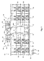
Die in
Stromabwärts einer die Drucktürme 01 bzw. Druckeinheiten 02 durchlaufenden Bahn 03, hier oberhalb der Drucktürme 01, ist je Sektion ein Überbau 04 vorgesehen, in welchen die Bahn 03 bzw. Bahnen 03 an Längsschneideinrichtungen 06 geschnitten, Teilbahnen mittels Wendeeinrichtungen 07 ggf. versetzt und/oder gestürzt, mittels in
Im Beispiel sind zwischen den Sektionen zwei Falzaufbauten 11 angeordnet, welche z. B. jeweils auf zwei verschiedenen übereinander liegenden Ebenen angeordnete Falztrichter aufweisen. Die Druckmaschine kann jedoch auch lediglich einen gemeinsamen, zwischen den Sektionen angeordneten Falzaufbau 11, oder aber lediglich eine Sektion und einen zugeordneten Falzaufbau 11 aufweisen. Auch kann der jeweilige Falzaufbau 11 mit nur lediglich einer Ebene von Falztrichtern ausgeführt sein. Jedem Falzaufbau 11 sind einer oder mehrere Falzapparate 12 zugeordnet.In the example, two
Die Druckeinheit 02 weist mehrere, im Beispiel vier, Druckwerke 13 auf, mittels welchem Farbe von einem Farbwerk 14 über zumindest einen als Formzylinder 16 ausgeführten Zylinder 16 auf die Bahn 03 aufbringbar ist (
Das Farbwerk 14 weist in vorteilhafter Ausführung einen über sechs Druckseiten reichenden Farbkasten 15 auf. In anderer Ausführung sind drei jeweils ca. zwei Druckseiten breite Farbkästen 15 in axialer Richtung nebeneinander angeordnet. Das Feuchtwerk 20 ist in vorteilhafter Ausführung als vierwalziges Sprühfeuchtwerk 20 ausgeführt.The inking
Der Formzylinder 16 besitzt in einer ersten Ausführung z. B. einen Umfang zwischen 850 und 1.000 mm, insbesondere von 900 bis 940 mm. Der Umfang ist z. B. zur Aufnahme zweier stehenden Druckseiten, z. B. Zeitungsseiten im Broadsheetformat, mittels zweier in Umfangsrichtung auf den Formzylinder 16 hintereinander fixierbarer Aufzüge 19, z. B. flexibler Druckformen 19, ausgebildet. Die Druckformen 19 sind in Umfangsrichtung auf dem Formzylinder 16 montierbar und bei der in
Die Länge L16 des nutzbaren Ballens des Formzylinders 16 beträgt in der ersten Ausführung z. B. 1.850 bis 2.400 mm, insbesondere 1.900 bis 2.300 mm und ist in axialer Richtung zur Aufnahme von z. B. mindestens sechs nebeneinander angeordneten stehenden Druckseiten, insbesondere Zeitungsseiten verschiedener Formate, z. B. im Broadsheet- und einem davon abweichenden Format, bemessen (siehe
In einer größeren Ausführung weist der Formzylinder 16 z. B. einen Umfang zwischen 980 und 1.300 mm, insbesondere von 1.000 bis 1.200 mm auf. Die Länge L16 des nutzbaren Ballens beträgt hierbei z. B. 1.950 bis zu 2.500, vorteilhaft 1.950 bis 2.400 mm, insbesondere 2.000 bis 2.400 mm. Die Belegung entspricht der o. g. Ausführung.In a larger version, the forme cylinder 16 z. B. a circumference between 980 and 1300 mm, in particular from 1000 to 1200 mm. The length L16 of the usable bale is in this case z. B. 1,950 up to 2,500, advantageously 1,950 to 2,400 mm, in particular 2,000 to 2,400 mm. The occupancy corresponds to the o. G. Execution.
Der Übertragungszylinder 17 besitzt in der ersten Ausführung ebenfalls einen Umfang z. B. zwischen 850 und 1.000 mm, insbesondere von 900 bis 940 mm. Die Länge L17 des nutzbaren Ballens des Übertragungszylinders 17 beträgt in der ersten Ausführung z. B. ebenfalls 1.850 bis 2.400 mm, insbesondere 1.900 bis 2.300 mm.The
Er ist in Längsrichtung nebeneinander mit lediglich dreidruckseitenbreiten Aufzügen 21, z. B. Druck- oder Gummitüchern 21, belegt (Abschnitte ABC und EFG). Sie reichen in Umfangsrichtung im wesentlichen um den vollen Umfang. Die Gummitücher 21 sind, das Schwingungsverhalten des Druckwerkes 13 im Betriebsfall günstig beeinflussend in Umfangsrichtung, z. B. um 180°, zueinander versetzt (
In der größeren Ausführung weist der Übertragungszylinder 17 z. B. einen Umfang zwischen 980 und 1.300 mm, insbesondere von 1.000 bis 1.200 mm auf. Die Länge L17 des nutzbaren Ballens beträgt hierbei z. B. 1.950 bis zu 2.500, vorteilhaft 1.950 bis 2.400 mm, insbesondere 2.000 bis 2.400 mm. Die Belegung mit Aufzügen 21 entspricht der ersten Ausführung.In the larger version, the transfer cylinder 17 z. B. a circumference between 980 and 1300 mm, in particular from 1000 to 1200 mm. The length L17 of the usable bale is in this case z. B. 1,950 up to 2,500, advantageously 1,950 to 2,400 mm, in particular 2,000 to 2,400 mm. The occupancy of
Durchmesser von Ballen der Zylinder 16; 17 liegen in der ersten o. g. Ausführung z. B. von 270 bis 320 mm, insbesondere von ca. 285 bis 300 mm. In der zweiten o. g. Ausführung liegt der Durchmesser von Ballen der Zylinder 16; 17 z. B. von ca. 310 bis 410 mm, insbesondere von 320 bis ca. 380 mm. Ein Verhältnis einer Länge des nutzbaren Ballens der Zylinder 16; 17 zu deren Durchmesser sollte bei 5,8 bis 8,8 liegen, z. B. bei 6,3 bis 8,0, in breiter Ausführung insbesondere bei 6,5 bis 8,0.Diameter of bales of
Als Länge L16; L17 des nutzbaren Ballens ist hier diejenige Breite bzw. Länge des Ballens zu verstehen, welche zur Aufnahme von Aufzügen 19; 21 geeignet ist. Dies entspricht in etwa auch einer maximal möglichen Bahnbreite einer zu bedruckenden Bahn 03. Bezogen auf eine gesamte Länge des Ballens der Zylinder 16; 17 wäre zu dieser Länge L16; L17 des nutzbaren Ballens noch die Breite von ggf. vorhandenen Schmitzringen, von ggf. vorhandenen Nuten und/oder von ggf. vorhandenen Mantelflächenbereichen hinzuzurechnen, welche z. B. zur Bedienung von Spann- und/oder Klemmvorrichtungen zugänglich sein müssen.As length L16; L17 of the usable bale here is to be understood that width or length of the bale, which for receiving
In vorteilhafter Ausführung weist der Satellitenzylinder 18 ebenfalls im wesentlichen die genannten Abmessungen und Verhältnisse, zumindest des zugeordneten Übertragungszylinders 17, auf.In an advantageous embodiment, the
Die Druckmaschine ist wie oben bereits erwähnt für die Herstellung verschiedener Produktformate, d. h. das Bedrucken von Bahnen 03 unterschiedlicher Breiten ausgelegt. Darunter ist hier nicht eine unterschiedliche Breite aufgrund von teilbreiten Bahnen gemeint, wie es bei "halben", "drittel", "zweidrittel breiten" Bahnen der selben Grundbahn der Fall wäre. Mit der unterschiedlichen Bahnbreite geht hier bei der selben Anzahl möglicher Seiten ein unterschiedliches Produktformat einher.The printing machine is as already mentioned above for the production of various product formats, i. H. the printing of
Form- und Übertragungszylinder 16; 17 weisen in einer besonders vorteilhaften Ausführung die in
In
Eine Seitenzahl der Zeitungsdruckseiten in axialer Richtung betrachtet ist z. B. in der ersten Betriebsart (Zeitungsdruck, F1) und der zweiten Betriebsart (Zeitungsdruck, F2) die selbe ist. Sie beträgt vorzugsweise sechs Seiten des entsprechenden Formates F1; F2.A page number of newspaper pages viewed in the axial direction is z. B. in the first mode (newspaper printing, F1) and the second mode (newspaper printing, F2) is the same. It is preferably six pages of the corresponding format F1; F2.
Die größere Breite b1 ist zum Bedrucken von sechs nebeneinander angeordneten Zeitungsseiten im ersten Format F1 geeignet und liegt z. B. bei 1.800 bis zu 2.500, vorteilhaft bei 1.900 bis 2.400 mm, insbesondere bei 1.900 bis 2.200 mm. Die kleinere Breite b2 ist zum Bedrucken von sechs nebeneinander angeordneten Zeitungsseiten im zweiten Format F2 geeignet und liegt z. B. bei 1.750 bis 2.100, vorteilhaft bei 1.750 bis 2.050 mm, bevorzugt zwischen 1.850 mm und 1.950 mm, wobei jedoch gilt b1 > b2. Die möglichen Breiten für den Zeitungsdruck sind nicht auf die beiden genannten, sondern für jede beliebig dazwischen liegende Breiten bzw. Formate anzuwenden. D. h. grundsätzlich sind also sämtliche Bahnen 03 verschiedenster Breiten (bzw. entsprechende Zeitungsformate) variierbar, welche z. B. von 1.750 mm bis 2.400 mm, zumindest von 1.850 und 2.200 mm liegen.The larger width b1 is suitable for printing six juxtaposed newspaper pages in the first format F1 and is z. B. at 1,800 to 2,500, advantageously at 1,900 to 2,400 mm, in particular at 1,900 to 2,200 mm. The smaller width b2 is suitable for printing six juxtaposed newspaper pages in the second format F2 and is z. B. at 1,750 to 2,100, advantageously at 1,750 to 2,050 mm, preferably between 1,850 mm and 1,950 mm, but where b1> b2. The possible widths for the newspaper printing are not to be applied to the two mentioned, but for any arbitrary intermediate widths or formats. Ie. In principle, therefore, all
Ebenfalls in
In zumindest einer der Betriebsarten trägt der Formzylinder 16 des Druckwerks 13 z. B. eine in axialer Richtung über zumindest drei Zeitungsseitenbreiten des aktuell betreffenden Formats F1; F2 reichende Druckform 19" (siehe unten). Diese ist dann beispielsweise nebeneinander mit Druckbildern dreier Zeitungsseiten bzw. einem insgesamt drei Zeitungsseiten entsprechendem Druckbild versehen, insbesondere belichtet. Ebenso befindet sich die Trichterspitze eines mittleren von drei nebeneinander angeordneten Falztrichtern 41; 42; 43 des Trichteraufbaus 11 in dieser Druckmaschinenmittelachse M (siehe unten).In at least one of the modes of the
Ebenfalls dargestellt in den
Anhand der
Für alle nachfolgenden Ausführungen zu den
In
Im Gegensatz zu
Vorzugsweise weisen die das kleinere Druckseitenformat F2 tragenden Druckformen 19" nicht lediglich die Breite der drei Druckseiten auf, sondern erstrecken sich bis zum Ende der wirksamen Mantelfläche des Formzylinders 16. Die beiden nebeneinander angeordneten Druckformen 19" weisen somit zusammen eine Breite entsprechend der maximalen bzw. der größeren Breite b1 der breiteren Bahn 03.1 auf. Damit ist über die gesamte wirksame Länge L16 des Formzylinders 16 ein gleichmäßigeres Transportverhalten unabhängig von der eben verwendeten Bahnbreite möglich und/oder die Gefahr eines Trockenlaufens des korrespondierenden Aufzuges 21 in den Randzonen bei Verwendung der schmaleren Bahn 03.2 vermindert. Die Druckformen 19" tragen dann die Druckbilder unsymmetrisch zu ihrer Breite und sind bei der Herstellung beispielsweise unsymmetrisch belichtet. Der nichtdruckende Randbereich beträgt 50 bis 100 mm.Preferably, the printing forms 19 "carrying the smaller printed page format F2 do not merely have the width of the three printed pages, but extend to the end of the effective lateral surface of the
In einer vorteilhaften Variante ist die Druckmaschine in einer Betriebsweise für den Druck von sechs nebeneinander angeordneten stehenden Druckseiten eines als Zeitungsformat F1; F2 ausgebildeten Formates F1; F2 (auf einer entsprechend breiten Bahn 03.1; 03.2) und in anderer Betriesweise für den Druck von vier nebeneinander angeordneten liegenden Druckseiten eines als Tabloidformat F3 ausgebildetes Format F3 betrieben bzw. betreibbar. Hierzu ist in den
Im Vorgriff auf das zu
In
In der zweiten Ausführung der o. g. Variante (
Die Nebenschnittlinien S4 und S5 können in der genannten Betriebsweise (Tabloid) in einer vorteilhaften Ausführung durch die selben Messer (s. u.) erzeugt werden wie in der anderen Betriebsweise für den Zeitungsdruck die Hauptschnittlinien S1 und S2, jedoch entsprechend anders axial positioniert. Somit genügen beispielsweise drei axial nebeneinander angeordnete Messereinheiten, wobei die mittlere in der Druckmaschinenmittelachse M - z. B. in axialer Richtung betrachtet ortsfest - und die beiden äußeren in axialer Richtung positionier- bzw. bewegbar angeordnet sind.The auxiliary cutting lines S4 and S5 can be produced in the aforementioned mode of operation (tabloid) in an advantageous embodiment by the same blades (see below) as in the US Pat another mode of operation for the newspaper printing the main cutting lines S1 and S2, but axially positioned differently according to different. Thus, for example, suffice three axially juxtaposed blade units, the average in the printing machine center axis M - z. B. stationary in the axial direction - and the two outer positioning in the axial direction or are arranged movable.
Es trägt somit wie dargestellt vorteilhaft in zumindest einer der Betriebsarten der Formzylinder 16 des Druckwerks 03 eine über zumindest drei Zeitungsseitenbreiten reichende Druckform 19". Wie oben dargelegt trägt in einer der Betriebsarten der Formzylinder 16 in axialer Richtung nebeneinander zwei über jeweils drei Zeitungsseitenbreiten des aktuell betreffenden Formats F1; F2 reichende Druckformen 19". In einer anderen Betriebsart trägt dann der Formzylinder 16 des Druckwerks 13 in axialer Richtung nebeneinander mehrere über jeweils eine Zeitungsseitenbreite des aktuell betreffenden Formats F1 reichende Druckformen 19.As shown above, in one of the modes of operation, the
Auch in der Betriebsart des Druckes größeren Formates F1, können dreifachbreite Druckformen 19" auf dem Formzylinder 16 angeordnet sein, welche dann ebenfalls nebeneinander mit Druckbildern dreier Zeitungsseiten des größeren Formates F1 versehen, insbesondere bebildert, sind.Also in the mode of printing larger format F1, triple-
In zumindest einer der Betriebsarten kann der Formzylinder 16 in axialer Richtung nebeneinander zwei über zwei Zeitungsseitenbreiten des aktuell betreffenden Formats F1; F2 reichende Druckformen 19'; 19" tragen.In at least one of the modes of operation, the
Der Formzylinder 16 weist in dargestellter Ausführung einen Umfang von zwei hintereinander angeordneten Druckseiten des größeren Zeitungsformats F1 auf und ist in Umfangsrichtung hintereinander mit zwei Druckformen 19; 19'; 19" belegt. Die Enden von zueinander axial fluchtenden Druckformen 19; 19'; 19" sind auf dem Formzylinder 16 vorzugsweise in durchgehenden Kanalöffnungen 28 angeordnet. Vorzugsweise sind die Druckformen 19; 19'; 19" dann in zwei in Umfangsrichtung zueinander um 180 ° versetzten, in axialer Richtung durchgehenden Kanalöffnungen 28 bzw. Kanälen 27 angeordnet.The
Die Breite b21 der Drucktücher 21 (siehe
In anderer Ausführung reichen die beiden Kanalöffnungen 38 jeweils über eine beiden Drucktüchern 21 entsprechende Breite.In another embodiment, the two
Die Breite b21 des dreifachbreiten Drucktuches 21 liegt z.B. bei 900 bis 1.250 mm, insbesondere bei 950 bis 1.200 mm, bevorzugt zwischen 1.000 mm und 1.100 mm.The width b21 of the triple-
Eine Breite b19" der dreifachbreiten Druckform 19" liegt ebenfalls z.B. bei 900 bis 1.250 mm, insbesondere bei 950 bis 1.200 mm, bevorzugt zwischen 1.000 mm und 1.100 mm.A width b19 "of the triple-
In nicht dargestellter Ausführung sind die beiden nebeneinander angeordneten Drucktücher 21 auf dem Übertragungszylinder 17 in axialer Richtung zueinander fluchtend und mit ihren Enden in einer einzigen, über die Länge des Übertragungszylinders 17 durchgehenden Kanalöffnung 38 angeordnet.In a non-illustrated embodiment, the two juxtaposed
Die Kanalöffnung 28 bzw. 38; 39 zur Aufnahme der Druckformenden und/oder der Drucktuchenden im Bereich der Mantelfläche weist vorzugsweise eine Breite in Umfangsrichtung von höchsten 5 mm, insbesondere von höchstens 3 mm auf.The
Die Aufzüge 19; 21 auf Form- und Übertragungszylinder 16; 17 des Druckwerks 13 sind wie in
Grundsätzlich sind die abgekanteten Enden 24; 26 der Aufzüge 19; 21 nun jeweils in eine am Umfang des jeweiligen Zylinders 16; 17 in Längsrichtung achsparallele, schlitzförmige Öffnung 28; 38; 39 einsteckbar, wobei die Enden 24; 26 beispielsweise durch ihre Formgebung, Reibung oder Verformung gehalten werden. Sie können jedoch auch zusätzlich mittels durch Federkraft, durch Druckmittel oder einer während des Betriebes wirksamen Fliehkraft betätigbarer Mittel fixierbar sein. Die schlitzförmigen Öffnungen 28 für in axialer Richtung nebeneinander angeordneter Druckplatten 19 auf dem Formzylinder 16 sind in vorteilhafter Ausführung jeweils in einer Flucht, z. B. als durchgehende schlitzförmige Öffnung 28, angeordnet, während die Öffnungen 38; 39 für die beiden auf dem Übertragungszylinder 17 nebeneinander angeordneten Gummitücher 21 nicht durchgehend, sondern zueinander in Umfangsrichtung um 180° versetzt sind.Basically, the folded ends 24; 26 of the
Das im folgenden zu den Aufzugenden 24; 26, und zu der Halteeinrichtung 29, 31 im Kanal des Formzylinders 16 beschriebene trifft in vorteilhafter Ausführung im wesentlichen auch auf den Kanal 36; 37 des Übertragungszylinders 17 zu. Daher sind in Klammern die entsprechenden Bezugszeichen in
In einer vorteilhaften Ausführung des Formzylinders 16 sind im Formzylinder 16 zwei Kanäle 27 vorgesehen, wobei sich beide Kanäle 27 durchgängig in axialer Richtung des Zylinders 16 zumindest über die gesamte Länge der sechs Abschnitte A bis F im Ballen erstrecken (siehe
Die abgekanteten Enden 24; 26 der Druckform 19; 21 sind nun jeweils in eine der am Umfang in Längsrichtung achsparallelen Öffnungen 28, (38; 39) einsteckbar und sind, zumindest das nachlaufende Ende 26, durch eine im Kanal 27; (36; 37) angeordnete Halteeinrichtung 29, 31 fixierbar.The folded ends 24; 26 of the
Die Halteeinrichtung 29, 31 weist hier zumindest ein Klemmstück 29, z. B. Klemmelement 29 und ein Federelement 31 auf (
In vorteilhafter Ausführung ist in jedem Kanal 27 des Formzylinders 16 nicht nur ein Klemmstück 29, sondern sind über die Länge der Abschnitte A bis F axial nebeneinander mehrere Klemmstücke 29 in der Art von Segmenten mit jeweils zumindest einem Federelement 31 angeordnet. Beispielsweise sind je Abschnitt A bis F mehrere, z. B. sechs, derartige Klemmstücke 29 angeordnet, wobei mittig zwischen den Klemmelementen 29 jeden Abschnittes A bis F, hier zwischen dem dritten und dem vierten Klemmelement 29 jedes Abschnittes A bis F, jeweils ein einen aufweisendes angeordnet sein kann. Der Registerstein bzw. Passerstift ist z. B. in einer Nut eines Sockels in axialer Richtung manuell verschieb- und justierbar. Der Registerstein kann in nicht dargestellter Weiterbildung auch jeweils über axial in einem frei bleibenden Hohlraum des Kanals 27 bzw. des Passelementes geführte Betätigungseinrichtung, z. B. eine motorisch antreibbare Gewindespindel, axial bewegbar sein.In an advantageous embodiment, not only a
Das Stellmittel 32 ist in der dargestellten Ausführungsform für den Formzylinder 16 derart ausgeführt, dass bei Betätigung die Halteeinrichtung(en) 29, 31, d. h. alle Klemmstücke 29, über die Länge der Abschnitte A bis F gleichzeitig geschlossen bzw. gelöst sind. Im Fall des Übertragungszylinders 17 gilt dies für Halteeinrichtung(en) 29, 31 des jeweiligen Bereichs ABC bzw. DEF. Das Stellmittel 32 ist hierbei für den Formzylinder 16 als jeweils mindestens über die Länge der Abschnitte A bis F reichender, und für den Übertragungszylinder 17 als jeweils mindestens über die Länge der Abschnitte ABZ bzw. DEF reichender im Kanal 27; 36; 37 verlaufender und mit Druckmittel betätigbarer reversibel verformbarer Hohlkörper 32, z. B. als Schlauch 32, ausgeführt. Dieser Schlauch 32 ist gemäß
In einer insbesondere in Verbindung mit den sechs Seiten breiten Druckeinheiten 02 bzw. Zylindern 16; 17 vorteilhaften Ausführungsform ist zumindest zwei Zylindern 16; 17, insbesondere zwei Formzylindern 16, mindestens einer der Drucktürme 01 jeweils eine Vorrichtung zum Andrücken eines Aufzugs 19; 21 an einen Zylinder 16; 17, insbesondere einer Druckform 19 an den Formzylinder 16, (im folgenden Andrückvorrichtung) zugeordnet. Dies ist z. B. von Vorteil, wenn in zwei korrespondierenden Druckwerken 13 ein schneller, z. B. fliegender Plattenwechsel vorgenommen werden soll. Insbesondere ist es für einen schnellen, sicheren und exakten Produktwechsel von Vorteil, wenn allen Formzylindern 16 eines Druckturmes 01 eine derartige Andrückvorrichtung zugeordnet ist. Eine entsprechende Andrückvorrichtung weist z. B. mindestens sechs Andrückelemente, z. B. Wälzelemente, auf, welche an die Aufzüge 19; 21 je Abschnitt A bis F einzeln wahlweise an- bzw. abstellbar sind. Hierdurch wird ein kontrolliertes und geführtes Einziehen bzw. Aufspannen und/oder Ablösen bzw. Abnehmen des Aufzuges 19; 21 ermöglicht. Auch ist es hierdurch möglich, ein Ende 24; 26 des Aufzuges 19; 21 in den entsprechenden Kanal 27; 36; 37 bzw. die Öffnung 28; 38; 39 hinein zu bewegen oder ein gelöstes Ende 24; 26 bzw. den teilweise gelösten Aufzug 19; 21 in einer gewünschten Lage niederzuhalten. Die Andrückvorrichtung erstreckt sich längs des Zylinders 16; 17 zumindest im gesamten Bereich der Abschnitte A bis F, d. h. im für das Drucken wirksamen Bereich des Ballens. Es können damit auf der Mantelfläche 30 des Zylinders 16 aufliegende Aufzüge 19 durch jeweils mindestens ein Andrückelement je nach Bedarf fixiert sein, während ein Ende 24; 26 eines Aufzugs 19 oder mehrerer Aufzüge 19 freigegeben ist bzw. sind, d. h. zu diesem Zeitpunkt nicht angedrückt ist bzw. sind.In a particularly in connection with the six pages
Die oben beschriebene Ausführung der Andrückvorrichtung ist insbesondere auch in Verbindung mit der in
In einer vorteilhaften Ausführung werden die Zylinder 16; 17; 18 der Druckeinheit 02 so angetrieben, dass die Druckwerke 13 der Druckeinheit 02 jeweils zumindest durch einen von den übrigen Druckeinheiten 13 mechanisch unabhängigen Antriebsmotor sowohl im Rüst- als auch im Produktionsbetrieb rotatorisch antreibbar sind. Im Fall der Satellitendruckeinheit 02 ist der bzw. sind die Satellitenzylinder 18 ebenfalls durch einen Antriebsmotor mechanisch unabhängig von den zugeordneten Druckwerken 13 rotatorisch antreibbar. Diese Antriebsmotoren sind vorzugsweise als bezüglich ihrer Winkellage geregelte Elektromotoren, z. B. als Asynchronmotoren, Synchronmotoren oder Gleichstrommotoren, ausgeführt. In vorteilhafter Weiterbildung ist zwischen dem jeweiligen Antriebsmotor und dem anzutreibenden Zylinder 16; 17; 18 bzw. Zylinderpaar 16, 17; 18, 18 mindestens ein Getriebe, insbesondere mindestens ein Untersetzungsgetriebe (wie zum Beispiel Ritzel-, Vorsatz- und/oder Planetengetriebe) angeordnet.In an advantageous embodiment, the
Von besonderem Vorteil weist das Feuchtwerk 20, insbesondere als Sprühfeuchtwerk 20, Schließelemente 48, sog. "Shutter" in den Randbereichen der möglichen Übertragungsbreite auf, welche wahlweise im Fall einer schmaleren Bahn 03.2; 03.3 in den Sprühweg eingebracht werden können. Je Randbereich ist zumindest ein derartiges Schließelement 48 vorgesehen, welches z. B. im wesentlichen eine Breite der halben Differenz zwischen der kleineren und größeren zum Druck vorgesehenen Breite b1; b2; b3 der Bahn 03.1; 03.2; 03.3 entspricht.
Im Farbwerk 14, insbesondere als Zonenfarbwerk 14 ausgeführt, werden je nach Betriebsweise bzw. zu bedruckender Bahn 03.1; 03.2; 03.3 nicht dargestellte Farmesser von Farbzonen im Randbereich wahlweise entweder grundsätzlich geschlossen oder zur bildgemäßen Steuerung der Farbmenge freigegeben.Run in the
Wie bereits in
In einer ersten baulichen Variante (schematisch in
In einer zweiten Variante (schematisch in
In
Die feste, auf einen festformatigen Zeitungsdruck ausgelegte Breite oder bei variablem Zeitungsdruck unverkleinerte Breite B42.1 zumindest des mittleren, ggf. jedoch aller dreier Falztrichter 41; 42; 43, liegt z. B. bei 600 bis 830 mm, vorteilhaft 630 bis 600 mm, insbesondere bei 630 bis 730 mm. Bei Falztrichtern 41; 42; 43 veränderlicher Breite liegt die Breite B42.2 zumindest des mittleren, ggf. jedoch aller dreier Falztrichter 41; 42; 43, z. B. bei ca. 580 bis ca. 700, vorteilhaft bei 580 bis 680 mm, bevorzugt zwischen ca. 616 mm und 650 mm. Beim variablen Falztrichter 41; 42; 43 liegt eine wählbare Differenz Δ beispielsweise zwischen 100 und 250 mm, insbesondere bei 120 bis 200 mm, wobei die Breiten aus den oben angegebenen Wertebereichen entsprechend zueinander gewählt sind. Für Δ/2 gilt entsprechend das halbe Maß.The fixed width, designed for a fixed-format newspaper print, or width B42.1, which is not reduced in the case of variable newspaper printing, of at least the middle, but if appropriate, of all three former 41; 42; 43, z. B. at 600 to 830 mm, advantageously 630 to 600 mm, in particular 630 to 730 mm. For
Die wirksame Breite b44 (Maximalbreite im oberen Trichterbereich) des Zusatztrichters 44 ist vorzugsweise signifikant größer als diejenige der (unverkleinerten) Falztrichter 41; 42; 43 der Trichtergruppe. Die breite sollte z. B. einen Faktor 1,05 bis 1,4, insbesondere 1,1 bis 1,3 größer sein, als eine unveränderbare oder die maximale Breite b41.1; b42.1; b43.1 der Falztrichter 41; 42; 43 der Trichtergruppe.The effective width b44 (maximum width in the upper hopper area) of the
In einer Variante z. B. gemäß
In vorteilhafter Ausführung weist die variable Druckmaschine ein oder mehrere der nachfolgend beschriebenen Führ- und/oder Bearbeitungselemente auf dem Weg der Bahn 03.1; 03.2; 03.3 durch die Druckmaschine auf:
- So ist es in vorteilhafter Ausgestaltung des Rollenwechslers 05 (
Fig. 1 und24 ) vorgesehen, dassTragarme 52 zu jeder Stirnseite einer abzuwickelndenRolle 53, in der Weise quer zur Druckmaschinenmittelachse M bewegbar auf einer Schwenkachse 54 gelagert sind, dass unabhängig von der Breite b1; b2; b3 der gerade verwendeten Bahn 03.1; 03.2; 03.3 dieRolle 53 so positionierbar ist, dass die Mittelebene m03 der aufgeachstenRolle 53 mit der Druckmaschinenmittelachse M zusammen fällt. Die hier als Führ- und/oder Bearbeitungselemente 52 wirksamen Tragarme 52 sind symmetrisch und quer zur Druckmaschinenmittelachse M gegensinnig zueinander positionierbar.
- So it is in an advantageous embodiment of the roll changer 05 (
Fig. 1 and24 ) provided thatsupport arms 52 to each end face of a unwindingroller 53, in the manner transverse to the printing press center axis M movable on a pivot axis 54th are stored, that regardless of the width b1; b2; b3 of the currently used web 03.1; 03.2; 03.3 theroller 53 can be positioned so that the median plane M03 of theaufgeachsten roller 53 coincides with the printing press center axis M. The effective here as a guide and / orprocessing elements 52support arms 52 are symmetrical and transversely to the printing machine center axis M in opposite directions positionable.
In der Darstellung von im folgenden beschriebenen Führ- und/oder Bearbeitungselementen werden z. T. die selben Bezugszeichen verwendet, wenn die zugeordneten Teile die selbe Funktionalität oder gar Ausgestaltung besitzen. Als Führ- und/oder Bearbeitungswerkzeuge werden hier und im folgenden auch Schneid-, Bahnleit-, Bahnantriebs- und/oder Bahnführungselemente, wie z. B. Andrückrollen, Wendestangen, Längsschneidmesser und/oder Führungswalzen verstanden.In the representation of the following described guide and / or processing elements z. T. the same reference numerals used when the associated parts have the same functionality or even design. As a guide and / or processing tools here and in the following also cutting, Bahnleit-, Bahnantriebs- and / or web guide elements, such. As pressure rollers, turner bars, longitudinal cutting blade and / or guide rollers understood.
Zusätzlich zur oder auch unabhängig von der Ausgestaltung der anderen Führ- und/oder Bearbeitungselemente kann im Einzugwerk 10 eine Zuggruppe 56 aus Zugwalze 57 und einer Mehrzahl von an diese wahlweise anstellbare Andrückrollen 58, z. B. Gummirollen, vorgesehen sein (
In anderer Ausführung einer Zuggruppe 61 - z. B. im Anschluss an die letzte von der jeweiligen Bahn 03 durchlaufenen Druckeinheit 02 oder aber vor dem Trichtereinlauf - weist diese als Andrückrollen 62 ausgeführte Führ- und/oder Bearbeitungselemente 62 auf, welche symmetrisch und quer zur Druckmaschinenmittelachse M gegensinnig zueinander positionierbar sind (
Die Längsschneideinrichtung 06; 65 weist wieder bevorzugt eine ungerade Anzahl von hier als Messer 66 ausgeführte Führ- und/oder Bearbeitungselemente 66 auf, welche symmetrisch und quer zur Druckmaschinenmittelachse M gegensinnig zueinander positionierbar sind. Vorzugsweise ist wieder das mittlere Führ- und/oder Bearbeitungselement 66 in der Flucht der Druckmaschinenmittelachse M wirksam und bzgl. einer Richtung quer zur Transportrichtung fest angeordnet, während sämtliche außermittigen Messer 66 quer zur Transportrichtung bewegbar und somit auf die Bahnbreite einstellbar ausgeführt sind. Die Positionierung erfolgt vorteilhaft wie in
In
Der Falzapparat 12 der Druckmaschine ist für sämtliche vorstehende Ausführungsbeispiele in vorteilhafter Ausführung siebenfeldrig ausgeführt.The
Der Umfang des Transportzylinders 77 entspricht mehr als fünf, insbesondere sieben Abschnittlängen bzw. sieben Längen der Signatur ("siebenfeidriger Transportzylinder 77"). Am Transportzylinder 77 sind in Umfangsrichtung hintereinander sieben in gleichen Abständen in die Umfangsfläche des Transportzylinders 77 eingelassene Halteeinrichtungen, z. B. Punkturleisten mit ausfahrbaren Punkturnadeln angeordnet (Punkturfalzapparat). Die Halteeinrichtungen können auch als Greifer ausgeführt sein (Greiferfalzapparat). Weiter sind sieben Schnittleisten angeordnet, welche vorzugsweise in Drehrichtung betrachtet jeweils geringfügig (z. B. 0,3 bis 3 cm) zu Lage der Klemmstelle (Greiferfalzapparat) bzw. dem Punkturdurchstich (Punkturfalzapparat) auf der Mantelfläche des Transportzylinders 77 beabstandet angeordnet sind. Auch der Umfang des Falzklappenzylinders 78 entspricht bevorzugt mehr als fünf, insbesondere sieben Abschnittlängen bzw. sieben Längen der Signatur.The circumference of the
Am Transportzylinder 77 sind ferner sieben Falzmesser angebracht, die jeweils bei Erreichen eines Spalts (je nach Sammel- oder Normalbetrieb jedes oder jedes mehrfache Mal) zwischen dem Transportzylinder 77 und einem Falzklappenzylinder 78 ausgefahren werden, um die am Transportzylinder 77 transportierten Signaturen an den Falzklappenzylinder 78 zu übergeben und zu falzen. Hierzu weist der Falzklappenzylinder 78 in Umfangsrichtung gleichmäßig beabstandet z. B. ebenso viele Falzklappen (nicht dargestellt) auf, wie die Anzahl der Falzmesser und/oder der Haltevorrichtungen am Transportzylinder 77, hier insbesondere sieben. Die gefalzten Produkte werden vom Falzklappenzylinder 78 an ein Schaufelrad 79 übergeben und von diesem auf eine Auslagevorrichtung 81, z. B. ein Förderband 81 ausgelegt.On the
Ein mit dem Transportzylinder 77 als Querschneideeinrichtung zusammen wirksamer Schneidzylinder 82 kann doppelt, d. h. zwei um eine Abschnittlänge voneinander beabstandete Messer am Umfang, oder auch vierfach groß, d. h. vier um eine Abschnittlänge voneinander beabstandete Messer am Umfang, ausgeführt sein.An effective with the
Die Konzeption der unsymmetrisch belichteten Panoramadruckformen, insbesondere zusammen mit zumindest einem von mehreren quer bewegbaren Falztrichtern 41; 42; 43 ist neben der sechs Seiten Breiten Maschine (sechs Druckbilder nebeneinander) auch auf andere Maschinen, insbesondere vier Seiten Breite Zeitungsdruckmaschinen (vier Druckbilder nebeneinander), anwendbar. Hierbei sind dann beispielsweise für die sechseitenbreite Maschine n = 3 Druckbilder und für die vierseitenbreite Maschine n = 2 Druckbilder in axialer Richtung nebeneinander auf einer Druckform 19", insbesondere unsymmetrisch, angeordnet. Hierfür ist in
In der anderen Betriebsweise mit einer schmaleren Bahn 03.2 weist der Formzylinder 16 nun Druckbilder des kleineren Formates F2 auf. Vorzugsweise sind nun die Druckformen 19" wieder als Panoramadruckformen 19", jedoch mit zwei Druckseiten des kleineren Formates F2, ausgeführt und reichen jedoch dennoch wieder im wesentlichen über den Bereich der möglichen Drucklänge der breiteren Bahn 03.1, d. h. sie weisen die selbe Breite auf wie Panoramadruckformen 19' des größeren Formates F1 auf. Die Druckformen 19" sind hierbei wie oben beschrieben z. B. wieder unsymmetrisch belichtet. Wie in der o. g. Anordnung mit drei Trichtern, ist auch hier ein Trichteraufbau vorteilhaft, wobei ein Abstand A1 der Falzebenen F42; F43 in der oben genannten Weise veränderbar ist.In the other mode of operation with a narrower web 03.2, the
Es sind dann wie in
Es wird explizit darauf hingewiesen, dass das folgende, zur Druckmaschine gemäß
Die Druckmaschine der
Es werden in der Konfiguration nach Zeile 3 auf zwei Falzapparaten (hier F1 und F3) zwei Produkte (2 x) mit jeweils 84 Seiten (pages p) aus jeweils 7 Bahnen (webs) erzeugt. Dies erfolgt hier in Broadsheetanornung (d. h. stehende Zeitungsseiten in Umfangsrichtung des Formzylinders 16, und in Doppelproduktion, d. h. im Betrieb ohne Sammeln (noncollect). Hierbei können z. B. an doppelt großen Formzylindern 16 jeweils hintereinander zwei selbe Druckformen 19; 19'; 19" aufliegen und damit ein doppelter Ausstoß an Produkten pro Zeiteinheit je Strang erzeugt werden, oder aber es können zwei verschiedene Produkte jeweils abwechselnd auf dem Strang erzeugt und entsprechend abwechselnd in zwei Produktströme ausgeschleust werden. Auf den ersten Falzapparat 12 von links (F1) werden beispielsweise zunächst vier im 4/4-Druck bedruckte Bahnen von der rechten Seite her, zwei im Druckturm links außen 1/4 und 4/1 bedruckte Bahnen und eine 4/4 im benachbarten Druckturm bedruckte Bahn geführt. Das Produkt weist 84 Seiten auf, von welchen 72 vierfarbig (und der Rest einfarbig) beduckt sind (84/72). Für das auf dem anderen Falzapparat (F3) erzeugte Produkt gilt hier das selbe. Die übrigen neun Zeilen der Tabelle sind in der selben Weise zu lesen, wobei z. B. in Zeile 6 auf zwei Falzapparaten (F1 und F3) jeweils aus 6 Bahnen (w) ein 72 Seiten (p.) starkes, 60 vierfarbige Seiten aufweisendes Produkt und auf einem Falzapparat (hier F2) ein 24-seitiges Produkt,In the configuration according to
In einer vorteilhaften Ausführung sind die Offsetdruckwerke 13 zumindest einer der Druckeinheiten 02 eines Druckturmes 11 (z. B. jedoch sämtlicher Druckeinheiten 02; 83 eines Druckturmes, vorteilhaft jedoch sämtlicher Druckeinheiten 02; 83 eines ganzen Druckmaschinenabschnittes, insbesondere jedoch sämtlicher Druckeinheiten 02; 83 der Druckmaschine) in der oben beschriebenen Ausführung mit dreiseitenbreiten Druckformen 19" und/oder dreiseitenbreiten Aufzügen 21 bestückt bzw. bestückbar ausgebildet.In an advantageous embodiment, the offset
Die Falzaufbauten 11 weisen z. B. mindestens eine Trichterebene, vorteilhaft jedoch zwei übereinander angeordnete Trichterebenen mit den drei nebeneinander befindlichen Falztrichtern 41 bis 43 (z. B. aus
Wie in der Draufsicht (untere Teilfigur) erkennbar, kann im dargestellten Falzaufbau 11 seitlich zur Gruppe der drei Falztrichter ein Zusatzfalztrichter 44 angeordnet sein. Dies kann für eine der beiden oder für beide ausgezogen dargestellten Trichterebenen der Fall sein, wenn diese beispielsweise jeweils wieder drei Falztrichter 41; 42; 43 nebeneinander aufweisen. Dieser Zusatztrichter kann die selbe Breite wie die anderen drei Falztrichter, jedoch wie zu
Einer oder mehrer der Drucktürme 01 können, wie hier als 01 a bezeichnet, Zusatzdruckeinheiten 83 aufweisen.One or more of the printing towers 01, as referred to here as 01 a,
In einem Ausführungsbeispiel einer Druckmaschine nach
Im Hinblick auf die sichere Bahnführung kann ein den Bahnzug einstellendes Einzugwerk ggf. noch vor der Wendestange 84, vorteilhaft jedoch zwischen Wendestange 84 und Eintritt in den Druckturm 01 vorgesehen sein.With regard to the safe web guide, the web tension adjusting feed mechanism may optionally be provided before the turning
Die seitliche Anordnung der Rollenwechsler 05 kann wieder für sich betrachtet, jedoch auch wieder in Verbindung mit einem oder mehreren o. g. vorteilhaften Merkmale besonderen Vorteil entfalten.The lateral arrangement of the
- 0101
- Druckturmprinting tower
- 0202
- Druckeinheit, Satellitendruckeinheit, Neunzylinder-Satelliten-Druckeinheit, Zehnzylinder-Satelliten-Druckeinheit, H-DruckeinheitPrinting unit, satellite printing unit, nine-cylinder satellite printing unit, ten-cylinder satellite printing unit, H printing unit
- 0303
- Materialbahn, BahnMaterial web, train
- 0404
- Überbausuperstructure
- 0505
- Rollenwechslerreelstands
- 0606
- LängsschneideinrichtungSlitter
- 0707
- Wendeeinrichtung, WendevorrichtungTurning device, turning device
- 0808
- Registereinrichtungregister means
- 0909
- Harfeharp
- 1010
- Einzugwerkinfeed
- 1111
- Falzaufbau, TrichteraufbauFalzaufbau, funnel construction
- 1212
- Falzapparatfolding
- 1313
- Druckwerk, OffsetdruckwerkPrinting unit, offset printing unit
- 1414
- Farbwerk, ZonenfarbwerkInking unit, zone inking unit
- 1515
- Farbkastenpaintbox
- 1616
- Zylinder, FormzylinderCylinder, forme cylinder
- 1717
- Zylinder, ÜbertragungszylinderCylinder, transfer cylinder
- 1818
- Druckzylinder, SatellitenzylinderPrinting cylinder, satellite cylinder
- 1919
- Aufzug, Druckform, Druckplatte, EinzeldruckformElevator, printing form, printing plate, single printing form
- 2020
- Feuchtwerk, SprühfeuchtwerkDampening unit, spray dampening unit
- 2121
- Aufzug, Drucktuch, Gummituch, MetalldrucktuchElevator, blanket, blanket, metal blanket
- 2222
- Schichtlayer
- 2323
- Trägerplattesupport plate
- 2424
- Ende, vorlaufendes, EinhängeschenkelEnd, leading, suspension leg
- 2525
- --
- 2626
- Ende, nachlaufendes, EinhängeschenkelEnd, trailing, suspension leg
- 2727
- Kanalchannel
- 2828
- Öffnung, KanalöffnungOpening, channel opening
- 2929
- Klemmstück, KlemmelementClamping piece, clamping element
- 3030
- Mantelflächelateral surface
- 3131
- Federelementspring element
- 3232
- Stellmittel, Hohlkörper, SchlauchAdjusting means, hollow body, hose
- 3333
- --
- 3434
- --
- 3535
- --
- 3636
- Kanalchannel
- 3737
- Kanalchannel
- 3838
- Öffnung, Kanalöffnung, SchlitzOpening, channel opening, slot
- 3939
- Öffnung, Kanalöffnung, SchlitzOpening, channel opening, slot
- 4040
- --
- 4141
- Falztrichter, Führ- und/oder BearbeitungselementForming former, guiding and / or processing element
- 4242
- Falztrichter, Führ- und/oder BearbeitungselementForming former, guiding and / or processing element
- 4343
- Falztrichter, Führ- und/oder BearbeitungselementForming former, guiding and / or processing element
- 4444
- Falztrichter, ZusatzfalztrichterForming hopper, additional folding hopper
- 4545
- --
- 4646
- Wendestangeturning bar
- 4747
- Ansatzelementneck element
- 4848
- Schließelementclosing element
- 4949
- Sprühquelle, Sprühbalken, BürstenwalzeSpray source, spray bar, brush roller
- 5050
- --
- 5151
- Walzeroller
- 5252
- Tragarm, Führ- und/oder BearbeitungselementSupport arm, guiding and / or processing element
- 5353
- Rollerole
- 5454
- Schwenkachseswivel axis
- 5555
- --
- 5656
- Zuggruppetraction group
- 5757
- Zugwalzepulling roller
- 5858
- Andrückrollecapstan
- 5959
- Antriebsmotordrive motor
- 6060
- --
- 6161
- Zuggruppetraction group
- 6262
- Andrückrolle, Führ- und/oder BearbeitungselementPressure roller, guiding and / or machining element
- 6363
- Gewindespindelscrew
- 6464
- Antriebsmotordrive motor
- 6565
- LängsschneideinrichtungSlitter
- 6666
- Messer, Führ- und/oder BearbeitungselementKnife, guiding and / or processing element
- 6767
- Gegenmesseragainst knife
- 6868
- Wendestange, Führ- und/oder BearbeitungselementTurning bar, guiding and / or processing element
- 6969
- Wendestangeturning bar
- 7070
- --
- 7171
- Falztrichterformers
- 7272
- Falztrichterformers
- 7373
- Falztrichterformers
- 7474
- Antriebsmotordrive motor
- 7575
- --
- 7676
- Trichtereinlaufwalze, ZugwalzeFunnel inlet roller, draw roller
- 7777
- Transportzylindertransport cylinder
- 7878
- Falzklappenzylinderjaw cylinder
- 7979
- Schaufelradpaddle wheel
- 8080
- --
- 8181
- Auslagevorrichtung, FörderbandDelivery device, conveyor belt
- 8282
- Schneidzylindercutting cylinder
- 03a03a
- Materialbahn, Bahn, TeilbahnMaterial web, web, partial web
- 03b03b
- Materialbahn, Bahn, TeilbahnMaterial web, web, partial web
- 03c03c
- Materialbahn, Bahn, TeilbahnMaterial web, web, partial web
- 03a103a1
- Materialbahn, TeilbahnMaterial web, partial web
- 03a203a2
- Materialbahn, TeilbahnMaterial web, partial web
- 03.103.1
- Materialbahn, Bahn, breitMaterial web, web, wide
- 03.203.2
- Materialbahn, Bahn, schmalMaterial web, web, narrow
- 03.303.3
- Materialbahn, BahnMaterial web, train
- 19'19 '
- Aufzug, Druckform, Einzeldruckform, PanoramadruckformElevator, printing form, single printing form, panoramic printing form
- 19"19 "
- Aufzug, Druckform, Einzeldruckform, PanoramadruckformElevator, printing form, single printing form, panoramic printing form
- AA
- Abschnittsection
- BB
- Abschnittsection
- CC
- Abschnittsection
- DD
- Abschnittsection
- Ee
- Abschnittsection
- FF
- Abschnittsection
- MM
- DruckmaschinenmittelachsePrinting press center axis
- A1A1
- Abstanddistance
- A2A2
- Abstanddistance
- F1F1
- Format, Druckseitenformat, ZeitungsformatFormat, printed page format, newspaper format
- F2F2
- Format, Druckseitenformat, ZeitungsformatFormat, printed page format, newspaper format
- F3F3
- Format, TabloidformatFormat, tabloid format
- F4F4
- Format, DruckseitenformatFormat, print page format
- F5F5
- Format, DruckseitenformatFormat, print page format
- F6F6
- Formatformat
- F7F7
- Sonderformatspecial format
- F8F8
- Sonderformatspecial format
- F41F41
- FalzebeneFalzebene
- F42F42
- FalzebeneFalzebene
- F43F43
- FalzebeneFalzebene
- S1S1
- HauptschnittlinieMain line
- S2S2
- HauptschnittlinieMain line
- S3S3
- HauptschnittlinieMain line
- S4S4
- NebenschnittlinienIn addition to cutting lines
- S5S5
- NebenschnittlinienIn addition to cutting lines
- L16L16
- Längelength
- L17L17
- Längelength
- II
- Länge (19; 21)Length (19; 21)
- b1b1
- Breite, BahnbreiteWidth, web width
- b2b2
- Breite, Bahnbreite, kleiner b1Width, web width, smaller b1
- b3b3
- Breite, Bahnbreite, kleiner b1 und b2Width, web width, smaller b1 and b2
- b19b19
- Breitewidth
- b19'b19 '
- Breitewidth
- b21b21
- Breitewidth
- h42h42
- Trichterhöhehopper height
- m03m03
- Mittelebenemidplane
- m19m19
- Mittelachsecentral axis
- s28s28
- Schlitzweiteslot width
- s38s38
- Schlitzweiteslot width
- s39s39
- Schlitzweiteslot width
- bF1bF1
- DruckseitenbreitePrint page width
- bF2bF2
- DruckseitenbreitePrint page width
- UFZ U FZ
- Umfang (16)Circumference (16)
- αα
- Winkelangle
- ββ
- Winkelangle
- α'α '
- Winkelangle
- ''
- entsprechende Bezeichnung einer zweiten Bahn bzw. Teilbahncorresponding designation of a second or partial web
Claims (27)
- Rotary printing machine with a printing unit (02) having a plate cylinder (16), the plate cylinder (16) having a printing plate (19") on its outer surface, which viewed in the axial direction of the plate cylinder (16) has print images of a number of printed pages of a certain format (F2) next to one another, characterised in that at least in one operating mode of the printing unit (02) the print images of n (with n > 1) fixed printed pages of a newspaper format (F2) are arranged on the printing plate (19") asymmetrically to an imaginary middle axis (m19) of the printing plate (19") extending to half the breadth (b19") of the printing plate (19") in its longitudinal direction.
- Rotary printing machine according to Claim 1, characterised in that the printing plates (19") has a breadth which corresponds to a breadth of the same number n of print images of a larger format (F1).
- Rotary printing machine according to Claim 1 or 2, characterised in that n is equal to 2.
- Rotary printing machine according to Claim 1 or 2, characterised in that n is equal to 3.
- Rotary printing machine according to Claim 3 or 4, characterised in that two such printing plates (19") are arranged next to one another in the longitudinal direction on the plate cylinder (16).
- Rotary printing machine according to Claim 3 or 4, characterised in that two such printing plates (19") are arranged one behind the other in the circumferential direction on the plate cylinder (16).
- Rotary printing machine according to Claim 3 or 4, characterised in that, viewed in the circumferential direction, only one such printing plate (19") is arranged on the plate cylinder (16).
- Rotary printing machine according to one of Claims 1 to 7, characterised in that the printing plate (19") is designed as a planographic printing plate for offset printing.
- Rotary printing machine according to Claim 2, characterised in that the length of the printing plate (19") in the circumferential direction essentially corresponds to the length of a printed page of the larger format (F1).
- Rotary printing machine according to Claim 2, characterised in that the plate cylinder (16) has a length (L16) in the axial direction of essentially six fixed newspaper page breadths of the larger format (F1) and the printing plate (19") has a breadth of three printed pages, in particular of the larger format (F1).
- Rotary printing machine according to Claim 2, characterised in that the plate cylinder (16) has a length (L16) in the axial direction of essentially four fixed newspaper page breadths of the larger format (F1) and the printing plate (19") has a breadth of two printed pages, in particular of the larger format (F1).
- Rotary printing machine according to Claim 10, characterised in that the three printed page-breadth printing plate (19") has a breadth of three printed pages of the larger format (F1) and is provided asymmetrically with print images of a smaller format (F2), in particular exposed asymmetrically with print images.
- Rotary printing machine according to Claim 11, characterised in that the two printed page-breadth printing plate (19") has a breadth of two printed pages of the larger format (F1) and is provided asymmetrically with print images of a smaller format (F2), in particular exposed asymmetrically with print images.
- Rotary printing machine according to Claim 12 or 13, characterised in that the print images are arranged equidistant to the multi-print page-breadth printing plate (19") in such a way that they are arranged in a direct sequence from a printing machine middle axis (M) outwards and a non-printing area remains in the edge area near to the front page.
- Rotary printing machine according to Claim 14, characterised in that the non-printing edge area is 50 to 100 mm.
- Rotary printing machine according to Claim 3 and 5, characterised in that a folder superstructure (11) with two folder formers (41; 42) arranged next to one another in a common machine plane diagonally to the web run direction is downstream of the printing system (13).
- Rotary printing machine according to Claim 16, characterised in that at least one, in particular both, of the folder formers (41; 42) is arranged to be movable diagonally to the web run direction.
- Rotary printing machine according to Claim 4 and 5, characterised in that a folder superstructure (11) having three folder formers (41; 42; 43) arranged next to one another in a common machine plane diagonally to the web run direction is downstream of the printing system (13).
- Rotary printing machine according to Claim 18, characterised in that at least the two outer folder formers of the three folder formers (41; 42) are arranged to be movable diagonally to the web run direction.
- Rotary printing machine according to Claim 1, characterised in that the printing system (13) has a transfer cylinder (16; 17) interacting with the plate cylinder (16), which carries only two printing blankets (21) next to one another in the axial direction on its circumference.
- Rotary printing machine according to Claim 3, characterised in that the printing system (13) has a transfer cylinder (16; 17) interacting with the plate cylinder (16), which carries only two printing blankets (21) next to one another in the axial direction on its circumference, and in that the printing blankets (21) in each case have a breadth in the axial direction of two fixed newspaper pages of the larger format (F1).
- Rotary printing machine according to Claim 4, characterised in that the printing system (13) has a transfer cylinder (16; 17) interacting with the plate cylinder (16), which carries only two printing blankets (21) next to one another in the axial direction on its circumference, and in that the printing blankets (21) in each case have a breadth in the axial direction of three fixed newspaper pages of the larger format (F1).
- Rotary printing machine according to Claim 3 or 4, characterised in that adjacent ends (24; 26) of printing plates (19") axially aligning to one another are arranged on the plate cylinder (16) in an uninterrupted channel opening (28).
- Rotary printing machine according to Claim 6, characterised in that adjacent ends (24; 26) of printing plates (19") axially aligning to one another are arranged on the plate cylinder (16) in an uninterrupted channel opening (28), and in that the printing plates (19") are arranged in two channel openings (28) uninterrupted in the axial direction and displaced by 180° to one another in the circumferential direction.
- Rotary printing machine according to Claim 1, characterised in that the printing plate (19") has a breadth (b19") of 950 to 1200 mm, in particular 950 to 1100 mm.
- Rotary printing machine according to Claim 20, characterised in that the printing blanket (21) has a breadth (b21) of 950 to 1200 mm, in particular 950 to 1100 mm.
- Rotary printing machine according to Claim 4, characterised in that the three printed pages-wide printing plate (19") is imaged, in particular exposed, next to one another with a print image corresponding to three newspaper pages or a number of print images together corresponding to three newspaper pages.
Applications Claiming Priority (5)
| Application Number | Priority Date | Filing Date | Title |
|---|---|---|---|
| DE102004022231 | 2004-05-04 | ||
| DE102004030062 | 2004-06-23 | ||
| DE102004033920A DE102004033920B4 (en) | 2004-05-04 | 2004-07-14 | Printing form of a printing machine and web-fed rotary printing press |
| US63142104P | 2004-11-30 | 2004-11-30 | |
| EP05744815A EP1742794B1 (en) | 2004-05-04 | 2005-04-29 | Rotary printing machine with a printing unit having a plate cylinder for printing a triple width at least |
Related Parent Applications (3)
| Application Number | Title | Priority Date | Filing Date |
|---|---|---|---|
| EP05744815.1 Division | 2005-04-29 | ||
| EP05744815A Division EP1742794B1 (en) | 2004-05-04 | 2005-04-29 | Rotary printing machine with a printing unit having a plate cylinder for printing a triple width at least |
| EP05744815A Division-Into EP1742794B1 (en) | 2004-05-04 | 2005-04-29 | Rotary printing machine with a printing unit having a plate cylinder for printing a triple width at least |
Publications (3)
| Publication Number | Publication Date |
|---|---|
| EP1908588A2 EP1908588A2 (en) | 2008-04-09 |
| EP1908588A3 EP1908588A3 (en) | 2011-05-25 |
| EP1908588B1 true EP1908588B1 (en) | 2012-08-01 |
Family
ID=39079633
Family Applications (1)
| Application Number | Title | Priority Date | Filing Date |
|---|---|---|---|
| EP08150699A Expired - Lifetime EP1908588B1 (en) | 2004-05-04 | 2005-04-29 | Rotary printing machine with a printing unit having a plate cylinder |
Country Status (1)
| Country | Link |
|---|---|
| EP (1) | EP1908588B1 (en) |
Families Citing this family (4)
| Publication number | Priority date | Publication date | Assignee | Title |
|---|---|---|---|---|
| DE102008018840A1 (en) * | 2008-04-15 | 2009-10-22 | Manroland Ag | Folding equipment following rotary printing machine, includes sliding guides for web, which can be positioned between other components along web path |
| CN103448352B (en) * | 2008-05-28 | 2015-09-09 | 柯尼格及包尔公开股份有限公司 | Roll-fed offset printing press and the method for running roll-fed offset printing press |
| DE102009027142B4 (en) * | 2009-06-24 | 2013-02-07 | Koenig & Bauer Aktiengesellschaft | Web-fed rotary printing press and method of controlling the web-fed rotary printing press |
| DE102010030267B4 (en) | 2010-06-18 | 2013-08-14 | Koenig & Bauer Aktiengesellschaft | Method and device for controlling a web-fed rotary printing press and method for operating a web-fed rotary printing press |
Family Cites Families (14)
| Publication number | Priority date | Publication date | Assignee | Title |
|---|---|---|---|---|
| DE2422696C2 (en) | 1974-05-10 | 1982-12-09 | M.A.N. Maschinenfabrik Augsburg-Nürnberg AG, 8900 Augsburg | Printing unit for one or two-sided printing with at least four cylinders |
| GB1476707A (en) | 1974-06-28 | 1977-06-16 | Rockwell International Corp | Printing plate arrangement |
| DE10016409B4 (en) | 1999-12-02 | 2007-03-15 | Koenig & Bauer Ag | Printing unit of a rotary printing machine |
| US4671501A (en) | 1986-06-23 | 1987-06-09 | Kabushiki Kaisha Tokyo Kikai Seisakusho | Turning-bar-less folding machine of W-width rotary press |
| DE4128797C2 (en) | 1991-08-30 | 1994-01-27 | Koenig & Bauer Ag | Paper web guide in web-fed rotary printing machines |
| DE4204254C2 (en) | 1992-02-13 | 1995-03-16 | Koenig & Bauer Ag | Device for longitudinal folding of several paper webs of the same width in a web-fed rotary printing press |
| US6024684A (en) | 1995-11-08 | 2000-02-15 | Koenig & Bauer Aktiengesellschaft | Device for producing folded items |
| DE19628647B4 (en) | 1996-07-16 | 2004-03-11 | Man Roland Druckmaschinen Ag | Ink transport roller for the inking unit of a web-fed rotary printing machine and method for producing the roller |
| DE59802100D1 (en) * | 1997-12-16 | 2001-12-13 | Koenig & Bauer Ag | PRINTED PRODUCT AND METHOD FOR PRODUCING A PRINTED PRODUCT |
| DE19803809A1 (en) * | 1998-01-31 | 1999-08-05 | Roland Man Druckmasch | Offset printing unit |
| US6152034A (en) | 1999-07-26 | 2000-11-28 | Heidelberger Druckmaschinen, Ag | Former board arrangement in a web-fed rotary newspaper printing press |
| EP1334825B1 (en) * | 1999-12-02 | 2011-06-01 | Koenig & Bauer Aktiengesellschaft | Printing unit of a printing machine |
| DE10111112B4 (en) | 2001-03-08 | 2005-12-22 | Vaw Aluminium Ag | Underblade shaft for a slitter-winder |
| US6868783B2 (en) * | 2001-09-07 | 2005-03-22 | Goss International Americas, Inc. | Printing press with multiple-image-carrying cylinder |
-
2005
- 2005-04-29 EP EP08150699A patent/EP1908588B1/en not_active Expired - Lifetime
Also Published As
| Publication number | Publication date |
|---|---|
| EP1908588A3 (en) | 2011-05-25 |
| EP1908588A2 (en) | 2008-04-09 |
Similar Documents
| Publication | Publication Date | Title |
|---|---|---|
| EP1820645B1 (en) | Rotary printing press with a folding assembly | |
| EP1466730B1 (en) | Web-fed rotary printing press | |
| EP1742794B1 (en) | Rotary printing machine with a printing unit having a plate cylinder for printing a triple width at least | |
| EP1434694A1 (en) | Arrangement for processing a web a folded product from a rotary roller press and a rotary roller press | |
| EP1742793B1 (en) | Offset printing group pertaining to a printing machine for printing newspapers | |
| EP1594698B1 (en) | Rotary roller printing press | |
| EP1908588B1 (en) | Rotary printing machine with a printing unit having a plate cylinder | |
| EP1556217B1 (en) | Printing machine | |
| DE10318477A1 (en) | Rotary printing press for newspaper printing, has printing unit for printing six axially adjacent pages and folding device with transport cylinder receiving seven cut product lengths | |
| EP1761384A1 (en) | Web-fed printing machine having a turning bar | |
| DE10321989A1 (en) | Printing press for offset printing has at least one extra printing unit on plane above printing location of upper satellite printing unit | |
| DE102004002984A1 (en) | Printing press for offset printing has at least one extra printing unit on plane above printing location of upper satellite printing unit | |
| DE20220298U1 (en) | Web-fed printing machine has printer unit printing width of six axially adjacent pages, with superstructure, at least one roller and folder and two printing towers | |
| EP1598184A2 (en) | Printing press, operational mode of the press and printing product | |
| DE20220296U1 (en) | Web-fed printing machine has printer unit printing width of six axially adjacent pages, with superstructure, at least one roller and folder and two printing towers | |
| DE202004021116U1 (en) | Printing press for offset printing has at least one extra printing unit on plane above printing location of upper satellite printing unit |
Legal Events
| Date | Code | Title | Description |
|---|---|---|---|
| PUAI | Public reference made under article 153(3) epc to a published international application that has entered the european phase |
Free format text: ORIGINAL CODE: 0009012 |
|
| AC | Divisional application: reference to earlier application |
Ref document number: 1742794 Country of ref document: EP Kind code of ref document: P |
|
| AK | Designated contracting states |
Kind code of ref document: A2 Designated state(s): AT BE BG CH CY CZ DE DK EE ES FI FR GB GR HU IE IS IT LI LT LU MC NL PL PT RO SE SI SK TR |
|
| AX | Request for extension of the european patent |
Extension state: AL BA HR LV MK YU |
|
| PUAL | Search report despatched |
Free format text: ORIGINAL CODE: 0009013 |
|
| AK | Designated contracting states |
Kind code of ref document: A3 Designated state(s): AT BE BG CH CY CZ DE DK EE ES FI FR GB GR HU IE IS IT LI LT LU MC NL PL PT RO SE SI SK TR |
|
| AX | Request for extension of the european patent |
Extension state: AL BA HR LV MK RS |
|
| 17P | Request for examination filed |
Effective date: 20110506 |
|
| AKX | Designation fees paid |
Designated state(s): AT BE BG CH CY CZ DE DK EE ES FI FR GB GR HU IE IS IT LI LT LU MC NL PL PT RO SE SI SK TR |
|
| REG | Reference to a national code |
Ref country code: DE Ref legal event code: R079 Ref document number: 502005012970 Country of ref document: DE Free format text: PREVIOUS MAIN CLASS: B41F0007100000 Ipc: B65H0045220000 |
|
| GRAP | Despatch of communication of intention to grant a patent |
Free format text: ORIGINAL CODE: EPIDOSNIGR1 |
|
| RIC1 | Information provided on ipc code assigned before grant |
Ipc: B41F 13/10 20060101ALI20120322BHEP Ipc: B65H 45/22 20060101AFI20120322BHEP Ipc: B41F 7/10 20060101ALI20120322BHEP |
|
| GRAS | Grant fee paid |
Free format text: ORIGINAL CODE: EPIDOSNIGR3 |
|
| GRAA | (expected) grant |
Free format text: ORIGINAL CODE: 0009210 |
|
| AC | Divisional application: reference to earlier application |
Ref document number: 1742794 Country of ref document: EP Kind code of ref document: P |
|
| AK | Designated contracting states |
Kind code of ref document: B1 Designated state(s): AT BE BG CH CY CZ DE DK EE ES FI FR GB GR HU IE IS IT LI LT LU MC NL PL PT RO SE SI SK TR |
|
| REG | Reference to a national code |
Ref country code: GB Ref legal event code: FG4D Free format text: NOT ENGLISH |
|
| REG | Reference to a national code |
Ref country code: AT Ref legal event code: REF Ref document number: 568563 Country of ref document: AT Kind code of ref document: T Effective date: 20120815 Ref country code: CH Ref legal event code: EP |
|
| REG | Reference to a national code |
Ref country code: IE Ref legal event code: FG4D Free format text: LANGUAGE OF EP DOCUMENT: GERMAN |
|
| REG | Reference to a national code |
Ref country code: DE Ref legal event code: R096 Ref document number: 502005012970 Country of ref document: DE Effective date: 20120927 |
|
| REG | Reference to a national code |
Ref country code: NL Ref legal event code: VDEP Effective date: 20120801 |
|
| REG | Reference to a national code |
Ref country code: LT Ref legal event code: MG4D Effective date: 20120801 |
|
| PG25 | Lapsed in a contracting state [announced via postgrant information from national office to epo] |
Ref country code: FI Free format text: LAPSE BECAUSE OF FAILURE TO SUBMIT A TRANSLATION OF THE DESCRIPTION OR TO PAY THE FEE WITHIN THE PRESCRIBED TIME-LIMIT Effective date: 20120801 Ref country code: LT Free format text: LAPSE BECAUSE OF FAILURE TO SUBMIT A TRANSLATION OF THE DESCRIPTION OR TO PAY THE FEE WITHIN THE PRESCRIBED TIME-LIMIT Effective date: 20120801 Ref country code: IS Free format text: LAPSE BECAUSE OF FAILURE TO SUBMIT A TRANSLATION OF THE DESCRIPTION OR TO PAY THE FEE WITHIN THE PRESCRIBED TIME-LIMIT Effective date: 20121201 Ref country code: CY Free format text: LAPSE BECAUSE OF FAILURE TO SUBMIT A TRANSLATION OF THE DESCRIPTION OR TO PAY THE FEE WITHIN THE PRESCRIBED TIME-LIMIT Effective date: 20120801 |
|
| PG25 | Lapsed in a contracting state [announced via postgrant information from national office to epo] |
Ref country code: SE Free format text: LAPSE BECAUSE OF FAILURE TO SUBMIT A TRANSLATION OF THE DESCRIPTION OR TO PAY THE FEE WITHIN THE PRESCRIBED TIME-LIMIT Effective date: 20120801 Ref country code: GR Free format text: LAPSE BECAUSE OF FAILURE TO SUBMIT A TRANSLATION OF THE DESCRIPTION OR TO PAY THE FEE WITHIN THE PRESCRIBED TIME-LIMIT Effective date: 20121102 Ref country code: SI Free format text: LAPSE BECAUSE OF FAILURE TO SUBMIT A TRANSLATION OF THE DESCRIPTION OR TO PAY THE FEE WITHIN THE PRESCRIBED TIME-LIMIT Effective date: 20120801 Ref country code: PT Free format text: LAPSE BECAUSE OF FAILURE TO SUBMIT A TRANSLATION OF THE DESCRIPTION OR TO PAY THE FEE WITHIN THE PRESCRIBED TIME-LIMIT Effective date: 20121203 Ref country code: PL Free format text: LAPSE BECAUSE OF FAILURE TO SUBMIT A TRANSLATION OF THE DESCRIPTION OR TO PAY THE FEE WITHIN THE PRESCRIBED TIME-LIMIT Effective date: 20120801 |
|
| PG25 | Lapsed in a contracting state [announced via postgrant information from national office to epo] |
Ref country code: NL Free format text: LAPSE BECAUSE OF FAILURE TO SUBMIT A TRANSLATION OF THE DESCRIPTION OR TO PAY THE FEE WITHIN THE PRESCRIBED TIME-LIMIT Effective date: 20120801 |
|
| PG25 | Lapsed in a contracting state [announced via postgrant information from national office to epo] |
Ref country code: DK Free format text: LAPSE BECAUSE OF FAILURE TO SUBMIT A TRANSLATION OF THE DESCRIPTION OR TO PAY THE FEE WITHIN THE PRESCRIBED TIME-LIMIT Effective date: 20120801 Ref country code: EE Free format text: LAPSE BECAUSE OF FAILURE TO SUBMIT A TRANSLATION OF THE DESCRIPTION OR TO PAY THE FEE WITHIN THE PRESCRIBED TIME-LIMIT Effective date: 20120801 Ref country code: RO Free format text: LAPSE BECAUSE OF FAILURE TO SUBMIT A TRANSLATION OF THE DESCRIPTION OR TO PAY THE FEE WITHIN THE PRESCRIBED TIME-LIMIT Effective date: 20120801 Ref country code: ES Free format text: LAPSE BECAUSE OF FAILURE TO SUBMIT A TRANSLATION OF THE DESCRIPTION OR TO PAY THE FEE WITHIN THE PRESCRIBED TIME-LIMIT Effective date: 20121112 Ref country code: CZ Free format text: LAPSE BECAUSE OF FAILURE TO SUBMIT A TRANSLATION OF THE DESCRIPTION OR TO PAY THE FEE WITHIN THE PRESCRIBED TIME-LIMIT Effective date: 20120801 |
|
| PG25 | Lapsed in a contracting state [announced via postgrant information from national office to epo] |
Ref country code: IT Free format text: LAPSE BECAUSE OF FAILURE TO SUBMIT A TRANSLATION OF THE DESCRIPTION OR TO PAY THE FEE WITHIN THE PRESCRIBED TIME-LIMIT Effective date: 20120801 Ref country code: SK Free format text: LAPSE BECAUSE OF FAILURE TO SUBMIT A TRANSLATION OF THE DESCRIPTION OR TO PAY THE FEE WITHIN THE PRESCRIBED TIME-LIMIT Effective date: 20120801 |
|
| PLBE | No opposition filed within time limit |
Free format text: ORIGINAL CODE: 0009261 |
|
| STAA | Information on the status of an ep patent application or granted ep patent |
Free format text: STATUS: NO OPPOSITION FILED WITHIN TIME LIMIT |
|
| 26N | No opposition filed |
Effective date: 20130503 |
|
| PG25 | Lapsed in a contracting state [announced via postgrant information from national office to epo] |
Ref country code: BG Free format text: LAPSE BECAUSE OF FAILURE TO SUBMIT A TRANSLATION OF THE DESCRIPTION OR TO PAY THE FEE WITHIN THE PRESCRIBED TIME-LIMIT Effective date: 20121101 |
|
| REG | Reference to a national code |
Ref country code: DE Ref legal event code: R097 Ref document number: 502005012970 Country of ref document: DE Effective date: 20130503 |
|
| BERE | Be: lapsed |
Owner name: KOENIG & BAUER A.G. Effective date: 20130430 |
|
| PG25 | Lapsed in a contracting state [announced via postgrant information from national office to epo] |
Ref country code: MC Free format text: LAPSE BECAUSE OF FAILURE TO SUBMIT A TRANSLATION OF THE DESCRIPTION OR TO PAY THE FEE WITHIN THE PRESCRIBED TIME-LIMIT Effective date: 20120801 |
|
| REG | Reference to a national code |
Ref country code: CH Ref legal event code: PL |
|
| REG | Reference to a national code |
Ref country code: IE Ref legal event code: MM4A |
|
| PG25 | Lapsed in a contracting state [announced via postgrant information from national office to epo] |
Ref country code: CH Free format text: LAPSE BECAUSE OF NON-PAYMENT OF DUE FEES Effective date: 20130430 Ref country code: BE Free format text: LAPSE BECAUSE OF NON-PAYMENT OF DUE FEES Effective date: 20130430 Ref country code: LI Free format text: LAPSE BECAUSE OF NON-PAYMENT OF DUE FEES Effective date: 20130430 |
|
| PG25 | Lapsed in a contracting state [announced via postgrant information from national office to epo] |
Ref country code: IE Free format text: LAPSE BECAUSE OF NON-PAYMENT OF DUE FEES Effective date: 20130429 |
|
| REG | Reference to a national code |
Ref country code: AT Ref legal event code: MM01 Ref document number: 568563 Country of ref document: AT Kind code of ref document: T Effective date: 20130429 |
|
| PG25 | Lapsed in a contracting state [announced via postgrant information from national office to epo] |
Ref country code: AT Free format text: LAPSE BECAUSE OF NON-PAYMENT OF DUE FEES Effective date: 20130429 |
|
| REG | Reference to a national code |
Ref country code: FR Ref legal event code: PLFP Year of fee payment: 11 |
|
| PG25 | Lapsed in a contracting state [announced via postgrant information from national office to epo] |
Ref country code: TR Free format text: LAPSE BECAUSE OF FAILURE TO SUBMIT A TRANSLATION OF THE DESCRIPTION OR TO PAY THE FEE WITHIN THE PRESCRIBED TIME-LIMIT Effective date: 20120801 |
|
| PG25 | Lapsed in a contracting state [announced via postgrant information from national office to epo] |
Ref country code: LU Free format text: LAPSE BECAUSE OF NON-PAYMENT OF DUE FEES Effective date: 20130429 Ref country code: HU Free format text: LAPSE BECAUSE OF FAILURE TO SUBMIT A TRANSLATION OF THE DESCRIPTION OR TO PAY THE FEE WITHIN THE PRESCRIBED TIME-LIMIT; INVALID AB INITIO Effective date: 20050429 |
|
| PGFP | Annual fee paid to national office [announced via postgrant information from national office to epo] |
Ref country code: GB Payment date: 20150424 Year of fee payment: 11 |
|
| PGFP | Annual fee paid to national office [announced via postgrant information from national office to epo] |
Ref country code: FR Payment date: 20150424 Year of fee payment: 11 |
|
| GBPC | Gb: european patent ceased through non-payment of renewal fee |
Effective date: 20160429 |
|
| REG | Reference to a national code |
Ref country code: FR Ref legal event code: ST Effective date: 20161230 |
|
| PG25 | Lapsed in a contracting state [announced via postgrant information from national office to epo] |
Ref country code: GB Free format text: LAPSE BECAUSE OF NON-PAYMENT OF DUE FEES Effective date: 20160429 Ref country code: FR Free format text: LAPSE BECAUSE OF NON-PAYMENT OF DUE FEES Effective date: 20160502 |
|
| PGFP | Annual fee paid to national office [announced via postgrant information from national office to epo] |
Ref country code: DE Payment date: 20180612 Year of fee payment: 14 |
|
| REG | Reference to a national code |
Ref country code: DE Ref legal event code: R119 Ref document number: 502005012970 Country of ref document: DE |
|
| PG25 | Lapsed in a contracting state [announced via postgrant information from national office to epo] |
Ref country code: DE Free format text: LAPSE BECAUSE OF NON-PAYMENT OF DUE FEES Effective date: 20191101 |