EP1594698B1 - Rotary roller printing press - Google Patents
Rotary roller printing press Download PDFInfo
- Publication number
- EP1594698B1 EP1594698B1 EP04725709A EP04725709A EP1594698B1 EP 1594698 B1 EP1594698 B1 EP 1594698B1 EP 04725709 A EP04725709 A EP 04725709A EP 04725709 A EP04725709 A EP 04725709A EP 1594698 B1 EP1594698 B1 EP 1594698B1
- Authority
- EP
- European Patent Office
- Prior art keywords
- cylinder
- web
- press according
- printing press
- fed rotary
- Prior art date
- Legal status (The legal status is an assumption and is not a legal conclusion. Google has not performed a legal analysis and makes no representation as to the accuracy of the status listed.)
- Expired - Lifetime
Links
- 238000010020 roller printing Methods 0.000 title 1
- 238000007639 printing Methods 0.000 claims abstract description 393
- 230000002093 peripheral effect Effects 0.000 claims abstract description 10
- 238000005520 cutting process Methods 0.000 claims description 79
- 238000012546 transfer Methods 0.000 claims description 53
- 238000003825 pressing Methods 0.000 claims description 28
- 238000011144 upstream manufacturing Methods 0.000 claims description 5
- 238000012856 packing Methods 0.000 claims 3
- 239000000047 product Substances 0.000 description 53
- 238000005096 rolling process Methods 0.000 description 41
- 238000004519 manufacturing process Methods 0.000 description 20
- 230000008901 benefit Effects 0.000 description 13
- 238000013461 design Methods 0.000 description 10
- 238000009826 distribution Methods 0.000 description 8
- 230000008859 change Effects 0.000 description 7
- 230000000295 complement effect Effects 0.000 description 7
- 238000011161 development Methods 0.000 description 6
- 230000009467 reduction Effects 0.000 description 6
- 239000003086 colorant Substances 0.000 description 5
- 239000000543 intermediate Substances 0.000 description 5
- 238000000034 method Methods 0.000 description 5
- 239000000725 suspension Substances 0.000 description 5
- 230000001154 acute effect Effects 0.000 description 4
- 238000005452 bending Methods 0.000 description 4
- 238000005516 engineering process Methods 0.000 description 4
- 239000000463 material Substances 0.000 description 4
- 241000196324 Embryophyta Species 0.000 description 3
- 230000005540 biological transmission Effects 0.000 description 3
- 230000009172 bursting Effects 0.000 description 3
- 239000007795 chemical reaction product Substances 0.000 description 3
- 238000010276 construction Methods 0.000 description 3
- 239000013067 intermediate product Substances 0.000 description 3
- 229910052751 metal Inorganic materials 0.000 description 3
- 239000002184 metal Substances 0.000 description 3
- 210000001331 nose Anatomy 0.000 description 3
- 238000007645 offset printing Methods 0.000 description 3
- 230000035515 penetration Effects 0.000 description 3
- 238000004904 shortening Methods 0.000 description 3
- 239000004575 stone Substances 0.000 description 3
- WYWHKKSPHMUBEB-UHFFFAOYSA-N 6-Mercaptoguanine Natural products N1C(N)=NC(=S)C2=C1N=CN2 WYWHKKSPHMUBEB-UHFFFAOYSA-N 0.000 description 2
- 241000287107 Passer Species 0.000 description 2
- 239000000969 carrier Substances 0.000 description 2
- 230000008878 coupling Effects 0.000 description 2
- 238000010168 coupling process Methods 0.000 description 2
- 238000005859 coupling reaction Methods 0.000 description 2
- 238000010017 direct printing Methods 0.000 description 2
- 238000005553 drilling Methods 0.000 description 2
- 230000003993 interaction Effects 0.000 description 2
- 230000008569 process Effects 0.000 description 2
- 238000012545 processing Methods 0.000 description 2
- 230000002441 reversible effect Effects 0.000 description 2
- 239000007921 spray Substances 0.000 description 2
- 229940095374 tabloid Drugs 0.000 description 2
- 240000005611 Agrostis gigantea Species 0.000 description 1
- 229910000838 Al alloy Inorganic materials 0.000 description 1
- 230000001133 acceleration Effects 0.000 description 1
- 230000000712 assembly Effects 0.000 description 1
- 238000000429 assembly Methods 0.000 description 1
- 238000009412 basement excavation Methods 0.000 description 1
- 230000015572 biosynthetic process Effects 0.000 description 1
- 238000004891 communication Methods 0.000 description 1
- 239000002131 composite material Substances 0.000 description 1
- 230000001143 conditioned effect Effects 0.000 description 1
- 230000004069 differentiation Effects 0.000 description 1
- 238000006073 displacement reaction Methods 0.000 description 1
- 230000000694 effects Effects 0.000 description 1
- 230000001747 exhibiting effect Effects 0.000 description 1
- 239000000945 filler Substances 0.000 description 1
- 239000006260 foam Substances 0.000 description 1
- 238000009957 hemming Methods 0.000 description 1
- 230000006698 induction Effects 0.000 description 1
- 238000012423 maintenance Methods 0.000 description 1
- 239000000203 mixture Substances 0.000 description 1
- 238000012986 modification Methods 0.000 description 1
- 230000004048 modification Effects 0.000 description 1
- 230000000149 penetrating effect Effects 0.000 description 1
- 230000001737 promoting effect Effects 0.000 description 1
- 230000001105 regulatory effect Effects 0.000 description 1
- 230000000284 resting effect Effects 0.000 description 1
- 238000000926 separation method Methods 0.000 description 1
- 239000007787 solid Substances 0.000 description 1
- 239000013589 supplement Substances 0.000 description 1
- 230000001360 synchronised effect Effects 0.000 description 1
- 238000012549 training Methods 0.000 description 1
- 238000005406 washing Methods 0.000 description 1
Images


Classifications
-
- B—PERFORMING OPERATIONS; TRANSPORTING
- B41—PRINTING; LINING MACHINES; TYPEWRITERS; STAMPS
- B41F—PRINTING MACHINES OR PRESSES
- B41F13/00—Common details of rotary presses or machines
- B41F13/54—Auxiliary folding, cutting, collecting or depositing of sheets or webs
- B41F13/56—Folding or cutting
- B41F13/60—Folding or cutting crosswise
-
- B—PERFORMING OPERATIONS; TRANSPORTING
- B41—PRINTING; LINING MACHINES; TYPEWRITERS; STAMPS
- B41F—PRINTING MACHINES OR PRESSES
- B41F13/00—Common details of rotary presses or machines
- B41F13/54—Auxiliary folding, cutting, collecting or depositing of sheets or webs
- B41F13/56—Folding or cutting
- B41F13/62—Folding-cylinders or drums
-
- B—PERFORMING OPERATIONS; TRANSPORTING
- B65—CONVEYING; PACKING; STORING; HANDLING THIN OR FILAMENTARY MATERIAL
- B65H—HANDLING THIN OR FILAMENTARY MATERIAL, e.g. SHEETS, WEBS, CABLES
- B65H45/00—Folding thin material
- B65H45/12—Folding articles or webs with application of pressure to define or form crease lines
- B65H45/16—Rotary folders
-
- B—PERFORMING OPERATIONS; TRANSPORTING
- B65—CONVEYING; PACKING; STORING; HANDLING THIN OR FILAMENTARY MATERIAL
- B65H—HANDLING THIN OR FILAMENTARY MATERIAL, e.g. SHEETS, WEBS, CABLES
- B65H45/00—Folding thin material
- B65H45/12—Folding articles or webs with application of pressure to define or form crease lines
- B65H45/22—Longitudinal folders, i.e. for folding moving sheet material parallel to the direction of movement
- B65H45/221—Longitudinal folders, i.e. for folding moving sheet material parallel to the direction of movement incorporating folding triangles
- B65H45/225—Arrangements of folding triangles
-
- B—PERFORMING OPERATIONS; TRANSPORTING
- B65—CONVEYING; PACKING; STORING; HANDLING THIN OR FILAMENTARY MATERIAL
- B65H—HANDLING THIN OR FILAMENTARY MATERIAL, e.g. SHEETS, WEBS, CABLES
- B65H45/00—Folding thin material
- B65H45/12—Folding articles or webs with application of pressure to define or form crease lines
- B65H45/28—Folding in combination with cutting
-
- B—PERFORMING OPERATIONS; TRANSPORTING
- B41—PRINTING; LINING MACHINES; TYPEWRITERS; STAMPS
- B41P—INDEXING SCHEME RELATING TO PRINTING, LINING MACHINES, TYPEWRITERS, AND TO STAMPS
- B41P2213/00—Arrangements for actuating or driving printing presses; Auxiliary devices or processes
- B41P2213/70—Driving devices associated with particular installations or situations
- B41P2213/73—Driving devices for multicolour presses
- B41P2213/734—Driving devices for multicolour presses each printing unit being driven by its own electric motor, i.e. electric shaft
-
- B—PERFORMING OPERATIONS; TRANSPORTING
- B65—CONVEYING; PACKING; STORING; HANDLING THIN OR FILAMENTARY MATERIAL
- B65H—HANDLING THIN OR FILAMENTARY MATERIAL, e.g. SHEETS, WEBS, CABLES
- B65H2511/00—Dimensions; Position; Numbers; Identification; Occurrences
- B65H2511/10—Size; Dimensions
- B65H2511/14—Diameter, e.g. of roll or package
Definitions
- the invention relates to a web-fed rotary printing press according to the preamble of claim 1.
- WO 03/031179 A2 is a printing press with printing units for printing six juxtaposed newspaper pages, a folding structure with two groups of three formers and a subsequent folder disclosed.
- Printing unit, folder assembly and folder can be driven by independent motors.
- the DE 25 28 008 A1 shows a printing machine for a direct printing process with form cylinders, which are equipped in the axial direction with six and in the circumferential direction with two printing plates and with counter-pressure cylinders, which are assignable in the axial direction with three and in the circumferential direction with a pressure felt. Both the pressure plates arranged next to one another and the pressure felts arranged next to one another are offset relative to each other in the circumferential direction.
- the DE 25 10 057 A1 discloses a printing machine with direct printing method, wherein the cooperating with a counter-pressure cylinder form cylinder carries six on its width and on its circumference two printing plates.
- JP 56-021860 A is a printing unit with form, transfer and impression cylinder known, each of the three cylinders is driven by its own drive motor.
- the printing units are designed as bridge printing units, wherein the transfer cylinders are covered with blanket sleeves.
- the WO 01/70608 A1 discloses a turner bar assembly, wherein two substantially part-wide turning bars are each arranged displaceably on a carrier transversely to the direction of the incoming partial web.
- a register roller is arranged, whose longitudinal axis extends substantially parallel to the side frame and which is also displaceable along a rail in a direction transverse to the direction of the incoming partial web.
- EP 1 072 551 A2 is a folding structure with two vertically offset groups of formers known. Above each of the groups of formers is a harp, ie a group of collection, acceptance or Harfenwalzen arranged over which the respective partial webs of the associated group of formers are fed.
- a harp ie a group of collection, acceptance or Harfenwalzen arranged over which the respective partial webs of the associated group of formers are fed.
- a folding structure is known, according to which cut, transversely offset to each other part webs are fed to different formers.
- the horizontally juxtaposed former are z. T. vertically offset from each other.
- the DE 4419 217 A1 shows a superstructure of a web-fed rotary printing press with a turning device, wherein partial webs are offset by half a partial web width, to guide them over each other and feed a common former.
- the EP 1 391 411 A1 discloses a folder, wherein a product portion to be imprinted is pressed by a pressure roller with a soft surface to the transport cylinder.
- DE 33 03 628 C2 is a co-operating with a counter-pressure cylinder knife cylinder for web-shaped Good discloses which in a representation of six, and in another illustration three knives in the circumferential direction one behind the other.
- the invention has for its object to provide a web-fed rotary printing press.
- the achievable with the present invention consist in particular in that a web-fed rotary printing press with a folder for high output, especially together with a triple wide printing machine, is created in safe operation.
- a transport cylinder is designed with a large circumference in order to ensure accordingly large positioning movements (cutting, holding, folding) at high production speeds safely.
- the increased radius of curvature reduces the pronounced oblique cut edge of the cross-cut product, especially in the case of strong products.
- the folder on a cutting cylinder with four cutting blades in the circumferential direction, d. H. he has a 4-fold extent of a section length.
- the 4-fold cutting cylinder and / or the pressure element interacts with a 7-piece transport cylinder. This is designed for executions of the folder with 4-piece cutting cylinder basically either as NOTEurzylinder or as a gripper cylinder.
- a geometrically conditioned significantly reduced tilting movement of the knife in the groove strips is caused by comparison with a 2-fold cutting cylinder.
- the four cutting blades or four section lengths (signatures) on the circumference having cutting cylinder (“four-circumference cutting cylinder") allows the use of significantly stronger bearings, a larger pin thickness and / or a stronger construction of the cylinder body itself, which contributes to increasing the stability. It can hereby stronger products (more layers) are cut because a higher force can be applied. For smaller product thicknesses may be due to the twisting and / or Low deflection increase the cutting accuracy.
- the folding apparatus has a pressure element, in particular a pressure cylinder, which serves the point needles when needling a strand (or strand bundle) as an abutment.
- a pressure element in particular a pressure cylinder, which serves the point needles when needling a strand (or strand bundle) as an abutment.
- the use of the pressure element is i.V.m. a running as NOTEurzylinder transport cylinder of particular advantage.
- the folder is designed to selectively in a collective mode - recording several product sections one above the other on the transport cylinder during more than one revolution before a delivery of these stacked layers to the following cylinder, in particular jaw cylinder takes place - and in non-collection mode - delivery of the product section to be operated during the first passage through the nip between the transport and jaw cylinders.
- An advantageous printing press has printing units with a width of the printing cylinder for printing six juxtaposed newspaper pages and one of the o. g folders.
- the forme cylinder of the printing unit then has a length for carrying one or more printing forms with a total of six juxtaposed newspaper pages - e.g. in broadsheet format - on.
- the folder in this case, for example, a funnel structure with three transverse to the direction of the tracks arranged transversely juxtaposed former.
- Similar advantages also apply to a printing machine in which a plurality, for example, six or more partial webs before the folder to be folded together to a fold. Furthermore, the embodiments are particularly advantageous for high-speed printing machines, ie high-speed printing units for paper speeds of, for example, 12 m / s and more.
- the number of reelstands (investment), the frequency of reel changes (production safety) and the set-up time when webs are drawn in (cycle times) can be reduced compared to a double-width press for the same product thickness.
- the printing units are designed as nine-cylinder satellite printing units, which on the one hand has a high precision in the color register and on the other hand a low-vibration construction result. Vibrations are also reduced by the advantageous arrangement, design and mounting of lifts on the cylinders.
- openings on the lateral surfaces in the circumferential direction are minimized.
- the openings may be arranged alternately offset in the circumferential direction, that acts at least on a section length always a closed lateral surface with the forming or satellite cylinder together.
- bales are provided on its entire effective length axially passing channels, but openings exist to the lateral surface only in the said sections.
- openings exist to the lateral surface only in the said sections.
- z. B designed as a form-fitting with pressure forming ends cooperating register pins which are arranged axially movable manually or remotely operable within the channel.
- the execution of the printing units with associated pressing devices is advantageous in terms of a register-accurate or register-accurate reproducible equipping the form cylinder with printing plates. It can be fixed with these resting on the lateral surface of the cylinder lifts by at least one pressing element as needed, while one end of an elevator or more elevators for removal or assembly is released or are.
- the mechanically independent of the cylinder pairs drive the (or the) satellite cylinder has particular advantages in terms of the possibility of variable operation. For example, during production, a setup, z. As a flying printing form change or washing done. Conversely, a web can be retracted while other cylinders or pairs of cylinders are standing or undergoing a set-up program. Also, it is advantageous to operate in the presence of rubber blankets with positive or negative promotional properties, the satellite cylinder with a different surface speed of the other cylinders.
- a superstructure of the printing press has at least one longitudinal cutting device with at least five knives spaced apart from one another transversely to the direction of travel of the paper.
- each printing tower (or eight printing locations) is provided with two register devices movable transversely to the direction of travel of the paper to compensate for paths of the partial webs. These can be structurally connected in each case with a part-web-wide turning devices. Also subsequent, only partial webs associated guide elements are z. B. executed essentially only partial web width substantially. These designs allow a low-vibration, and thus tailor-made transport of the web. By inertia Long, strong, caused only by the sub-orbit (s) guide elements caused web tension fluctuations (for example, load changes, change in printing speed) can be effectively reduced.
- sub-webs from one of a funnel group associated harp of the other funnel group can be acted upon and vice versa.
- only one of two stacked formers is a so-called. Harp, d. H. several i. d. R. non-driven Auflaufwalzen (also collectors or take-off rolls called) to pre-allocate.
- On the other formers then tracks from the common harp can be transferred.
- the two vertically stacked formers can be supplied from the same escape of superimposed sub-webs strands of variable thickness or partial web number.
- the partial web is displaceable or offset only by an odd multiple of half the partial web width. So it can be z. B. avoid with little effort to print very narrow webs too need to provide or additional pressure units.
- the transversely movable to the web execution at least one of the turning bars allows a high variability.
- the mechanically independent of the printing units drive rollers of the hopper structure and / or the folding apparatus is particularly advantageous in terms of a good registration and a variable operation.
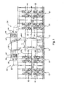
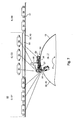
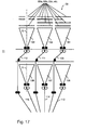
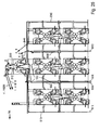
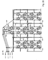
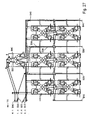
- the web-fed printing press shown by way of example in FIG. 1 has a left and a right section each having at least two printing towers 01.
- the printing towers 01 have printing units 02, which z. B. at least three times wide, ie for the printing of six axially juxtaposed newspaper pages executed.
- the printing units 02 are designed as satellite printing units 02.
- the advantageous embodiment of the printing units 02 as nine-cylinder satellite printing units 02 ensures a very good Passerhaltmaschine or a low fan-out.
- printing units 02 can also be used as ten-cylinder satellite printing units 02 or possibly also as printing units that can be operated in rubber-against-rubber printing, such as, for example, printing.
- B. be executed a plurality of bridge printing units or a H-printing unit 02.
- the printing units 02 are webs 03 supplied by rollers, not shown, in particular using reel changers.
- a superstructure 04 Downstream of the printing towers 01 or printing units 02 continuous web 03, here above the printing towers 01, a superstructure 04 is provided for each section, in which the web 03 or webs 03 cut on longitudinal cutting devices 06, sub-webs by means of turning devices 07 possibly offset and / or fallen, by means of in Fig. 1 only indicated register means 08 are aligned in the longitudinal register to each other and can be performed one above the other.
- the superstructure 04 has at least one so-called harp 09 with a number of superimposed webs 03 or part webs 03a; 03b; 03c leading harp or caster rollers.
- the harp 09 determines the funnel inlet of the superimposed tracks 03. About this harp 09, the tracks 03 undergo a change in direction and are subsequently summarized either as a strand or as multiple strands and fed to at least one folding structure 11.
- two Falz admittedten 11 are arranged between the sections, which z. B. each have arranged on two different superposed planes folding former.
- the printing machine can also have only one common folding structure 11 arranged between the sections, or else only one section and one associated folding structure 11. Also, the respective folding structure 11 may be performed with only one level of formers.
- Each folder assembly 11 are associated with one or more folders 12.
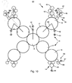
- the printing unit 02 has several, in the example four, printing units 13, by means of which ink from an inking unit 14 via at least one designed as a forme cylinder 16 Cylinder 16 can be applied to the web 03 (Fig. 2).
- the printing unit 13 is designed as offset printing unit 13 for the wet offset and has in addition to the inking unit 14, a dampening unit 20 and another cylinder 17 designed as a transfer cylinder 17.
- the transfer cylinder 17 forms a pressure point with an abutment-forming impression cylinder 18.
- the printing cylinder 18 is designed as a satellite cylinder 18 which forms further pressure points with further transfer cylinders 17 further printing units 13 in the print-on position.
- the printing cylinder 18 could also be designed as a transfer cylinder 18 in the formation of the printing units as a double printing unit in the rubber counter-rubber pressure.
- the same parts are given the same reference numerals, as far as they are not necessary for differentiation. However, a difference in the spatial position may exist and, in the case of the assignment of the same reference numbers, is generally disregarded.
- the inking unit 14 has, in an advantageous embodiment, an ink fountain 15 extending over six print pages. In another embodiment, three each color about two pages wide ink boxes 15 are arranged side by side in the axial direction.
- the dampening unit 20 is designed in an advantageous embodiment as allocate to the dampening 20.
- the form cylinder 16 has in a first embodiment z. B. a circumference between 850 and 1,000 mm, in particular from 900 to 940 mm.
- the scope is z. B. for receiving two stationary printed pages, z.
- the printing plates 19 can be mounted on the forme cylinder 16 in the circumferential direction and, in the case of the embodiment shown in FIG. 3, can be exchanged individually in each case as a single printing plate equipped with a printing side in the axial direction.
- the length L16 of the usable bale of the forme cylinder 16 is in the first Execution z. B. 1,850 to 2,400 mm, in particular 1,900 to 2,300 mm and is in the axial direction for receiving z. B. at least six juxtaposed standing printed pages, especially newspaper pages in broadsheet format, dimensioned (see Fig. 3, sections A to F). Among other things, it depends on the nature of the product to be produced, whether in each case only one pressure side or several pressure sides in the axial direction are arranged side by side on a printing plate 19. In an advantageous broader variant of the first embodiment, the length L16 of the usable bale is between 2,000 and 2,400 mm.
- the forme cylinder 16 has z. B. a circumference between 980 and 1300 mm, in particular from 1000 to 1200 mm.
- the length L16 of the usable bale is in this case z. B. 1,950 to 2,400 mm, in particular 2,000 to 2,400 mm.
- the occupancy corresponds to the o. G. Execution.
- the transfer cylinder 17 also has a circumference z in the first embodiment. B. between 850 and 1,000 mm, in particular from 900 to 940 mm.
- the length L17 of the usable bale of the transfer cylinder 17 is in the first embodiment z. B. 1,850 to 2,400 mm, in particular 1,900 to 2,300 mm and is in the longitudinal direction of each other z. B. with three elevators 21, z. B. blankets 21, occupied (sections AB to EF). They extend in the circumferential direction substantially to the full extent.
- the length L17 of the usable bale is also between 2,000 and 2,400 mm.
- the transfer cylinder has 17 z. B. a circumference between 980 and 1300 mm, in particular from 1000 to 1200 mm.
- the length L17 of the usable bale is in this case z. B. 1,950 to 2,400 mm, in particular 2,000 to 2,400 mm.
- the occupancy of elevators 21 corresponds to the first embodiment.
- Diameter of bales of cylinders 16; 17 are in the first o. G. Execution z. B. from 270 to 320 mm, in particular from about 285 to 300 mm. In the second o. G. Execution is the diameter of bales of the cylinder 16; 17 z. B. from about 310 to 410 mm, in particular from 320 to about 380 mm. A ratio of a length of the usable bale of the cylinders 16; 17 to the diameter should be 5.8 to 8.8, z. B. at 6.3 to 8.0, in a wide version, especially at 6.5 to 8.0.
- length L16; L17 of the usable bale here is to be understood that width or length of the bale, which for receiving elevators 19; 21 is suitable. This corresponds approximately to a maximum possible web width of a web to be printed 03. Based on an entire length of the bale of the cylinder 16; 17 would be L16 to this length; L17 of the usable bale nor the width of any existing Schmitzringen, possibly existing grooves and / or possibly existing lateral surface areas added, which z. B. for the operation of clamping and / or clamping devices must be accessible.
- the satellite cylinder 18 also substantially the dimensions and ratios of at least the associated transfer cylinder 17 substantially.
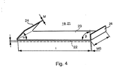
- Elevators 19; 21 are shown schematically in Fig. 4 z. B. executed as a flexible plates, wherein the designed as a blanket 21 elevator 21 as a so-called.
- Metal blanket 21 with a arranged on a support plate 23 elastic and / or compressible layer 22 (dashed lines) is executed (in Fig. 4 are alone the metal blanket 21 relevant reference numerals attached).
- a plate-shaped printing plate 19 and a support plate 23 for a rubber blanket is usually made of a flexible, but otherwise dimensionally stable material, for. B. of an aluminum alloy, and has two opposite, in or on the cylinder 16; 17 too fastening ends 24; 26 with a material thickness MS of z. B.
- a leading end 24 is, for example, at an acute angle ⁇ of 40 ° to 50 °, in particular 45 °, and a trailing end 26 at an angle ⁇ of 80 ° to 100 °, in particular 90 °, folded.
- the folded ends 24; 26 of the elevators 19; 21 each in a on the circumference of the respective cylinder 16; 17 longitudinally axially parallel, slot-shaped opening can be inserted, wherein the ends 24; 26, for example, be held by their shape, friction or deformation. However, they can also be fixed by means of spring force, by pressure medium or an effective during operation centrifugal force operable means.
- the slot-shaped openings for juxtaposed in the axial direction of pressure plates 19 on the forme cylinder 16 are in an advantageous embodiment in each case in alignment, z. B. arranged as a continuous slot-shaped opening (as described below), while the openings for the juxtaposed on the transfer cylinder 17 blankets 21 are not continuously, but alternately offset from each other in the circumferential direction by 180 °.
- Fig. 5a and b shows a perspective view of an example of an advantageous embodiment of the forme cylinder 16.
- two channels 27 are provided, both channels 27 throughout in the axial direction of the cylinder 16 at least over the entire length of the six sections A to F in the bale extend (Fig. 5b). They are in the circumferential direction of the cylinder 16 z. B. offset by 180 ° to each other.
- a slot width s16 of the opening 28 on the forme cylinder 16 in the circumferential direction is less than 5 mm and is preferably in the range of 1 mm to 3 mm (FIG. 5c).
- the folded ends 24; 26 of the printing plate 19 are now each in one of the circumferentially axially parallel openings 28 can be inserted and are, at least the trailing end 26, fixed by a arranged in the channel 27 holding device 29, 31.
- the holding device 29, 31 here has at least one clamping piece 29 and a spring element 31 (FIG. 5c).
- the not shown right angle beveled trailing suspension legs 26 (see Fig. 4) is preferably at a substantially complementary shaped for folding wall of the opening 28 to the plant and is pressed there by the clamping piece 29 by a force exerted by the spring element 31 on the clamping piece 29 force.
- the not shown pointed angled leading catch leg 24 (see Fig. 4) is preferably at a substantially complementary shaped for folding wall of the opening 28, which with the lateral surface 30 a hooking edge or nose at an acute angle ⁇ 'from 40 ° to 50 °, in particular 45 ° forms to the plant.
- an adjusting means 32 is provided in the channel 27, which counteracts the force exerted by the spring element 31 on the clamping piece 29 in its operation force and the clamping piece 29 pivots away from the wall or the end 26.
- each channel 27 not only a clamping piece 29, but over the length of the sections A to F axially adjacent a plurality of clamping pieces 29 in the manner of segments each having at least one spring element 31 is arranged (in Fig. 5a from the cylinder 16 "pulled out” shown).
- each section A to F more, z. B. six, such clamping pieces 29 as shown in FIG. 5c, wherein centrally between the clamping elements 29 of each section A to F, here between the third and the fourth clamping element 29 of each section A to F, respectively, a register stone 35 exhibiting Passer element 33 (Fig 5d) is arranged.
- index block 35 can in unillustrated development also via axially guided in a vacant cavity of the channel 27 and the fitting element 33 actuator z.
- a motor-driven threaded spindle be axially movable.
- the adjusting means 32 is designed in the illustrated embodiment such that when actuated the holding device (s) 29, 31, d. H. all of the clamping pieces 29 are closed or released simultaneously over the length of the sections A to F.
- the adjusting means 32 is "pulled out” as shown in Fig. 5a from the cylinder 16 as at least over the length of the sections A to F reaching, axially extending in the channel 27 and actuated by pressure reversibly deformable hollow body 32, z. B. as a hose 32, executed.
- This tube 32 is shown in FIG. 5c with the clamping pieces 29 cooperating so arranged in the channel 27 that he counteracts the self-locking the holding device closing spring elements 31 upon actuation. It is passed through the regions of registration elements 33 (FIG. 5d).
- Fig. 6a and b shows in a perspective view an example of an advantageous embodiment of the transfer cylinder 17.
- the cylinder 17 are two channels 36; 37 provided, wherein both channels 36; 37 continuously in the axial direction of the cylinder 17 at least over the entire length of the six sections A to F and three sections AB; CD; EF, in bale extend (Figure 6b). They are in the circumferential direction of the cylinder 17 z. B. offset by 180 ° to each other.
- Two of the three openings 38; 39 are in communication with the same channel 36 and are aligned with each other in the axial direction, but spaced from each other on the lateral surface 40.
- Axial between the two openings 38; 39 is a the shape of the remaining lateral surface 40 continuing, in particular undisturbed section U without opening.
- a slot width s17 of the uncovered opening 38; 39; 41 on the transfer cylinder 17 in the circumferential direction is less than 5 mm in each case and is preferably in the range of 1 mm to 3 mm (FIG. 6c).
- radially extending bores 42 may be provided, which in the operating state of the cylinder 17 by means of a plug, not shown, closed or closed (Fig. 6b).
- the plug has an outer surface which continues the otherwise cylindrical contour of the cylinder 17 in the mounted state in the region of the bore 42.
- the openings 38 In the circumferential direction of the cylinder 17 in a section perpendicular to the axis of rotation in an advantageous embodiment only one of the openings 38; 39; 41 or one of the shortened by the plug opening 38; 39; 41 arranged one behind the other. In this section, the openings 38 thus overlap; 39; 41 or shortened by the plug opening 38; 39; 41 not.
- the folded ends 24; 26 of the blanket 21 are now each in one of the circumferentially axially parallel openings 38; 39; 41 inserted and are, at least the trailing end 26, respectively by at least one in the channel 36; 37 arranged holding device 43, 44 fixable.
- the two ends 24; 26 of the same blanket 21 through the same opening 38; 39; 41 in the same channel 36; 37 led.
- the holding device 43, 44 has here in each case at least one clamping piece 43 and a spring element 44 (FIG. 6c).
- the right angle beveled trailing suspension legs 26 (see FIG. 4), not shown, preferably comes to a wall of the opening 38 that is essentially complementary to the fold; 39; 41 to the system and is pressed there by the clamping piece 43 by a force exerted by the spring element 44 on the clamping piece 43 force.
- the not shown pointed angled leading catch leg 24 (see Fig. 4) preferably comes at a substantially complementary shaped for folding wall of the opening 38; 39; 41, which forms a hooking edge or nose at an acute angle ⁇ 'of 40 ° to 50 °, in particular 45 ° with the lateral surface 40, to the plant.
- each channel 36; 37 not only a clamping piece 43, but are over the length of the sections AB; CD; EF axially next to each other a plurality of clamping pieces 43 as individual segments, each with at least one spring element 44 arranged (in Fig. 6a "pulled out" of the cylinder 17 shown).
- sections AB; CD; EF of the respective channel 36; 37 which have no opening to the lateral surface 40, is instead of the holding device 43, 44 or the holding devices 43, 44th at least one filling element 49 (Figure 6d) in the channel 36; 37 arranged.
- this filling elements 49 as individual segments in the relevant, no opening having section AB; CD; EF of the channel 36; 37 arranged.
- Centered between the retainers 43, 44 of each section AB; CD; EF, ie in the region between the sections A and B or E and F, here between the fifth and sixth clamping element 43, may also be arranged in each case one filling element 49 (FIG. 6d).
- the filling element 49 has substantially the cross section of the channel 36; 37 imitated cross-section and at least one axially continuous opening 51, through which a means for the actuating means 46; 47; 48 is feasible.
- the adjusting means 46; 47; 48 is designed in the illustrated embodiment such that when actuated the holding means 43, 44 of a section AB; CD; EF, ie all clamping pieces 43 of a section AB; CD; EF, simultaneously closed or solved.
- the adjusting means 46; 47; 48 is shown "pulled out" of the cylinder 17 in FIG. 6a.
- an adjusting means 46 extends at the front side; 47 over at least the corresponding length of the section AB; EF.
- the middle opening 41 associated adjusting means 48 also extends over at least the corresponding length of the associated portion CD.
- the adjusting means 46; 47; 48 are each as axially in the channel 36; 37 extending and pressure-actuated reversibly deformable hollow body 46; 47; 48, z. B. as a hose 46; 47; 48, executed.
- This hose 46; 47; 48 is shown in FIG. 6c with the clamping pieces 43 so cooperating in the channel 36; 37 arranged to counteract the self-locking the holding device 43, 44 closing spring elements 44 when actuated.
- FIG. 6d Through the regions of filling elements 49 to be passed, it is passed through this or its opening 51 (FIG. 6d).
- channels 36; 37 these can also not be carried out continuously over the entire length.
- the channels 36; 37 in the area of each section AB; CD; EF one channel 36 each; 37, possibly provided with a corresponding holding device, wherein the channel 37 of the central elevator 21 is offset from the two outer by 180 °. This is indicated only schematically in Fig. 6e.
- 17 advantageous embodiment is at least two cylinders 16; 17, in particular two forme cylinders 16, at least one of the printing towers 01 each have a device 52 for pressing an elevator 19; 21 to a cylinder 16; 17, in particular a printing plate 19 to the forme cylinder 16, (hereinafter Andrückvorraum 52) assigned.
- This is z. B. advantageous if in two corresponding printing units 13 a faster, z. B. flying plate change to be made.
- a corresponding pressing device 52 has one or more pressing elements 53; 54, z. B.
- the pressing device 52 extends along the cylinder 16; 17 at least in the entire range of sections A to F, d. H. in the effective for printing area of the bale.
- the embodiment of the pressing device 52 described in FIG. 7 is particularly also in connection with the embodiment described in FIG. 5 for all sections A to F reaching common actuating means 32 of advantage.
- this constellation a single or group-wise mounting, changing and / or removing is also possible for six next to each other on the forme cylinder 16 arranged printing plates 19, without having to take place within the forme cylinder 16 an increased amount of controls or equipment supply. The manufacturing, assembly and maintenance simplifies considerably.
- the pressing device 52 has sections A to F (in the case of six elevators 19 arranged next to each other) or section AB; CD; EF (in three juxtaposed elevators 21) at least a first pressure element 53, z. B. rolling element 53, on.
- it has sections A to F or section AB; CD; EF in a circumferential direction of the cylinder 16; 17 spaced from this first rolling element 53 second pressing element 54, z. B. rolling element 54, on.
- FIG. 7 in the case of the forme cylinder 16, only central portions B, C and D and the rolling elements 53 associated with these portions B, C and D are provided; 54 is shown.
- Each section A to F or AB to EF is a first rolling element 53 or a group of axially adjacent to each other first rolling elements 53 and z.
- B. a second rolling element 54 or a group of axially juxtaposed second rolling elements 54 are arranged.
- a first rolling element 53 and a group of three second rolling elements 54 are shown per section A to F or AB to EF.
- the arrangement of groups of at least two independently movable rolling elements 53 is advantageous with regard to the risk of possible tilting and possibly faulty axial alignment. 54.
- a single rolling element 53; 54 for a section A to F and AB to EF for example, as in the longitudinal direction almost over the length of the section A to F and AB to EF extending roller 53; 54 executed, a rolling element 53; 54 of a group, however, z. B. only as the highest a fraction of the length of the section A to F and AB to EF having roller 53; 54th
- the axially juxtaposed rolling elements 53; 54 and, if provided, the circumferentially successively arranged rolling elements 53; 54 are in principle independently movable on, for example, a traverse 56 (or more traverses 56) arranged.
- the single first rolling element 53 or the group of first rolling elements 53 of each section A to F or AB to EF and, if provided, the single second rolling element 54 or the group of second rolling elements 54 of each section A to F and AB to EF are independent of each other by their own adjusting means 57; 58 actuated.
- These adjusting means 57; 58 are, for example, as reactable with pressure medium reversibly deformable hollow body 57; 58, in particular as a hose 57; 58 executed. But it can also be provided differently type of electrically or magnetically actuable actuating means.
- the first or first rolling elements 53 assigned to this section A to F or AB to EF and, if provided, the second rolling elements 54 assigned to this section A to F or AB to EF are coupled to the cylinder 16; 17 or to be wound up, already hinged elevator 19; 21 hired.
- first and / or second rolling elements 53 which concern this section A to F or AB to EF, will also be arranged; 54 to the respective elevator 19; 21 hired.
- first and second rolling elements 53; 54 presses when rolling the cylinder 16; 17 with the rolling elements 53; 54, the second rolling element 54, the trailing bent end 26 of the elevator 19; 21 in rolling into the opening 28; 38; 39; 41.
- Is or only first rolling elements 53 are provided, it is pushed in through them.
- the rolling elements 53 remain; 54 stationary, while the cylinder 16; 17 is rotated in a direction of production P.
- the holding means After the holding means has changed from its release position to its holding position, all rolling elements 53; 54 of the respective section A to F and AB to EF from the cylinder 16; 17 or its elevator 19; 21 turned off.
- Does the pressing device 52 each have first and second rolling elements 53; 54, the elevators to be left 19; 21 advantageously held down by at least the second rolling elements 54.
- first at least the second rolling element 54 is turned off, so that the end 26 of the channel 27; 36; 37 can escape, and the first rolling element 53 employed, so that the already partially dissolved elevator 19; 21 still on the cylinder 16; 17 is managed and held.
- the cylinder 16; 17, preferably counter to the direction of production P are rotated until the leading end 24 of the channel 27; 36; 37 removed, and the elevator 19; 21 can be removed.
- the rolling elements 53; 54 of the not to be solved elevator 19; 21 concerned sections A to F and AB to EF during the procedure, in principle, any operating positions, preferably off, occupy.
- the cylinder 16; 17; 18 of the printing unit 02 driven so that the printing units 13 of the printing unit 02 are rotatably driven in each case at least by one of the other printing units 13 mechanically independent drive motor 61.
- the satellite cylinder or cylinders 18 are likewise rotationally drivable by a drive motor 61, mechanically independently of the associated printing units 13.
- the drive motors 61 are preferably as with respect to their angular position controlled electric motors 61, z. B. as induction motors, synchronous motors or DC motors.
- the drive motor 61 and the driven cylinder 16; 17; 18 or cylinder pair 16, 17; 18, 18 at least one gear 62, in particular at least one reduction gear 62 (such as pinion, attachment and / or planetary gear) arranged.
- the individual drives contribute to high flexibility and to avoid vibrations in the mechanical drive system, and thus also to high quality in the product.
- FIGS. 8 to 10 only the components of the right-hand half of the figure have corresponding reference numerals, since the left-hand side corresponds to the right-hand mirror image.
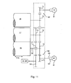
- Fig. 8 all nine cylinders 16; 17; 18 each have their own drive motor 61, which in each case z. B. via a gear 62 on the cylinder 16; 17; 18 drives.
- the inking unit 14 shown above has, in addition to other, not designated rolls two distribution cylinders 63, which rotationally together by means of its own drive motor 64 are drivable.
- the two distribution cylinders 63 are axially movable and driven by an unillustrated drive means for generating an axial stroke.
- the inking unit 14 shown below has only one distribution cylinder 63.
- the dampening unit 20 shown above has, in addition to other, not designated rolls on two distribution cylinders 66 which are rotationally driven together by means of a separate drive motor 67.
- the two distribution cylinders 66 are axially movable and driven by an unillustrated drive means for generating an axial stroke.
- the dampening unit 20 shown below has only one distribution cylinder 66.
- the two cylinders 16; 17 each printing unit 13 in the embodiment of FIG. 9 each driven by a common drive motor 61 on the transfer cylinder 17.
- the drive can be axial, z. B. via a gear 62, done or via a on a drive wheel of the transfer cylinder 17 driving pinion. From the drive wheel of the transfer cylinder 17 can then be driven off to a drive wheel of the forme cylinder 16.
- the drive connection 68 (shown as a connecting line) can be made as a gear connection or via belt and is executed encapsulated in development.
- the color and possibly dampening unit 14; 20 via their own drive motors 64; 67 or a cylinder 16; 17; In principle, it is to be applied to the one shown in FIG.
- the two cylinders 16; 17 of each printing unit 13 in the embodiment of FIG. 10 although in each case by a common drive motor 61, but driven on the forme cylinder 16.
- the drive can again axially, z. Example, via a gear 62, done or via a on a drive wheel of the forme cylinder 16 driving pinion. From the drive wheel of the forme cylinder 16 can then on a drive wheel of the Transfer cylinder 17 are driven off.
- the drive connection 68 may be designed as set forth in FIG. 9.
- For the drive of the color and possibly dampening unit 14; 20 via their own drive motors 64; 67 or a cylinder 16; 17; 18 is again basically to apply to Fig. 8 executed.
- the drive motor 61 drives via a pinion 71 on a rotationally rigidly connected to the forme cylinder 16 drive wheel 72, which in turn drives on a torsionally rigidly connected to the transfer cylinder 17 drive wheel 73.
- the drive wheel 73 is either widened or it is a second drive 74 connected to the transfer cylinder 17.
- the widened or additional drive wheel 73; 74 drives via a rotatably mounted on a pin 76 of the forme cylinder 16 drive wheel 77 on a drive wheel 78 of the inking and / or dampening unit 14; 20.
- the drive wheels 72; 73; 74; 77; 78 are preferably designed as gears.
- the forme cylinder 16 is axially displaceable in an axially displaceable manner by, for example, ⁇ ⁇ L
- at least the pinion 71 and the drive wheels 72 to 74 are made straight toothed.
- drive motor 61 and the gear 62 of pinion 71 and drive wheel 72 may additionally be a dashed lines indicated, encapsulated auxiliary gear 62 'may be arranged.
- the drive to the forme cylinder 16 can also take place axially on the journal 76, wherein, if appropriate, an axial movement of the forme cylinder 16 takes place via an unillustrated, axial relative movement between the forme cylinder 16 and the drive motor 61 receiving coupling.
- the satellite cylinder 18 is also shown in this illustration via a pinion 71 on an associated drive wheel 79, in particular gear 79, driven.
- Each driven by an independent drive motor 61 drive train is in an advantageous embodiment, at least for themselves, possibly encapsulated in even smaller units (stichliiert shown in Fig. 11).
- the described embodiments of the printing unit 02 and the printing units 13 and their cylinders 16; 17; 18 and the drive allows a low-vibration, accurate printing high quality with a low on the achievable product strength technical and spatial complexity.
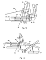
- FIG. 12 shows, in a perspective oblique view, a first exemplary embodiment of at least part of the superstructure 04.
- the partial track 03b is shown in FIG. 12 as a partial track 03b turned from the center to the outside.
- a second of the partial webs 03a; 03c could also be turned into another flight, for example, by means of a second such turning device 07.
- a second turning device can, for. B. above or below the first turning device 07 lie.
- the turning device 07 has, as a guide element 82, as usual, two parallel or crossed turning bars 82, which with the transport direction of the incoming part web 03a; 03b; 03c form an angle of about 45 ° or 135 °, and by means of which an incoming web 03a; 03b; 03c is laterally displaceable and / or can be staggered.
- the turning bars 82 advantageously have a length L82, the projection of which on the transverse extent of the incoming partial web 03a; 03b; 03c insignificantly larger, z. B. 0% to 20% greater than the width of the incoming partial web 03a; 03b; 03c, ie the length L82 is approximately 1.4 to 1.7 times the partial web width.
- At least the length L82 is selected such that its projection is less than or equal to twice the width of a two-side width partial web 03a; 03b; 03c, ie the length L82 is at most 2.8 times the partial web width.
- the turning bars 82 are each mounted individually on carriers 83, which transverse to the direction of the incoming partial web 03a; 03b; 03c can be moved on at least one guide 84.
- the now “short” turning bars 82 can now bring depending on the requirements of the desired web guide in the required position. Under certain circumstances, both turning bars 82 may be mounted on such a carrier 83.
- the register device 08 has, as a guide element 86, at least one roller 86 which can be moved parallel to the running direction.
- the roller 86 or a plurality of rollers 86 of the register device 08 advantageously have a length L86 which is insignificantly larger, for. B. 0% to 20% greater than the width of the incoming partial web 03a; 03b; 03c is.
- At least the length L86 is less than or equal to twice the width of a two-side-width partial web 03a; 03b; 03c.
- the register device 08 is transverse to the direction of the incoming partial web 03a; 03b; 03c stored on at least one guide 87 movable. The now narrow register device 08 or its short rollers 86 can now be brought to the required position from the desired web guide as required.
- Harp 09 (Fig. 1) is supplied.
- For straight from running webs 03 or partial webs 03a; 03b; 03c is in the superstructure 04 upstream of the harp roller 89, for example, over the full web width b03 reaching, in the transport direction spatially variable register roller 91 and a guide roller 92 is arranged.
- the "short" harp roller 88 is realized as a section 88 of a harp roller 89 which is divided in this embodiment but has a total width of over six web pages 03.
- the sections 88 are rotatably supported independently of each other here.
- the required register device 08 at least one of the course of the partial web 03a; 03b; 03c determining guide elements, such. B. the turning device 07 or a turning bar 82 or the harp 09 or a "short" harp roller 93, are assigned.
- the "short" register device 08 z. B. associated with one of the "short” turning bars 82 and together with this on the guide 84 transversely to the direction of the incoming part web 03b locally variable.
- this arrangement is shown here for crossed turning bars 82, but to apply to parallel turning bars 82 of FIG.
- Turning bars 82 is at least one (here two) guide roller 97 with perpendicular to the axis of rotation of the roller 81 extending axis of rotation.
- the guides 84; 96 (FIGS. 13 and 14) of the mentioned exemplary embodiments can be realized in many different ways.
- the guides 84; 96 be designed as spindles with at least sections threaded, which rotatably mounted on both sides and z. B. are rotatably driven by a drive, not shown.
- the carriers 83; 94 can in the manner of sliding blocks in rigid guides 84; 96, z. B. on profiles, be performed.
- a drive of the carrier 83; 94 also via a drivable spindle or otherwise done.
- transversely adjustable turning bar 82 By means of the transversely adjustable turning bar 82 are variable transfers or offset of partial webs 03a; 03b; 03c over one or two partial web widths (or even multiples of a half partial web width) away possible.
- the printed partial webs 03a; 03b; 03c in the flight of one of several, here three, transverse to the direction of juxtaposition of the former 101; 102; 103 (FIG. 15) of the folding structure 11.
- the transfer takes place, for example, to meet the requirement of different strengths of individual strands or ultimately intermediate or end products, at the same time an effective printing with the fullest possible web widths should be made.
- the superstructure 04 advantageously has at least (n * (m / 2 - 1)) turning devices 07.
- n * (m / 2 - 1) the number of tracks to be printed 03; 03 '(eg n printing towers 01) of a respective maximum width b03 of m printed pages.
- the superstructure 04 advantageously has at least (n * (m / 2 - 1)) turning devices 07.
- three tracks 03; 03 '(or three printing towers 01) per section are six turning devices 07 per section of advantage.
- a printing press with z. B. two sections of three printing towers 01 and a total of six provided for the two-sided four-color four printing pages wide webs 03; 03 '; 03 "are arranged at least three turning devices 07 per section.
- a printing machine with z. B two sections of two printing towers 01 and a total of four provided for the two-sided four-color printing six printed pages wide webs 03; 03 '; 03 ", four turning devices 07 are arranged per section, for example, and in this printing machine with two sections or a total of four printing towers 01 (four webs 03, 03 '), a product with a total thickness of, for example, 96 pages is collected
- an operating mode is advantageous in which a partial web 03a, 03b, 03c is an odd multiple of half the partial web width b03a and / or funnel width (ie by the factor This can be achieved by means of long turning bars (not shown) reaching across the entire width of the printing machine or the width b03 of the entire web 03, but also advantageously by means of
- the reversible rods 82 are then arranged, for example, as shown in Fig.
- the partial track 03a offset by an odd multiple of half the funnel width b101 or partial track width b03a; 03b; 03c thus runs "between" the formers 101; 102; 103.
- the part track 03a offset by an odd multiple of half the part track width b03a; 03b; 03c is in front of the former 101; 102; 103 in a between the two aligned folding hoppers 101; 102; 103 lying escape longitudinally cut and runs on the folding structure 11 and the harp 09, d. H. undivided and / or split harp roller 89 and / or "short" harp roller 93, to ( Figure 16).
- FIG. 16 is a schematic sectional view of FIG. 15 with harp rollers 89 shown by way of example differently.
- 93 wherein, for example, the partial web 03c has been offset from its original position (shown unfilled) by one and a half partial web widths b03a. It can, for example, if they are provided with a further longitudinal cutting device 104 in front of the formers 101; 102; 103 is cut (then in each case one printed page or newspaper page wide), each half in each case with the partial webs 03a and 03b on each of a former 101; 102 are led. The two (intermediate) products then have z. B.
- a total product has z. B. 48 pages. If this printing machine is operated in double production, ie the forme cylinder 16 is in the circumferential direction with two printing plates 19 same printed pages A1, A1; to F1, (or A1 ', A1' to F1 ', F1') occupied and in the folder 12 is not collecting, so are on the strands 109, 111 and 112, two identical successive issues of the above page numbers generated. It is a total product with z. B. only 24 pages, but produced with double output.
- the harp rollers 89; 93 in particular if they are executed undivided over the full length, can be rotationally driven in a development on its own, not shown drive motors. These are then z. B. with respect to their speed, u. U. also their location, run adjustable and are to take over current setpoints with the machine control or an electronic master in connection.
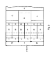
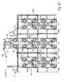
- the folding structure 11 has at least two stacking hoppers 101, 106 arranged one above the other; 102, 107; 103, 108, whose planes of symmetry S in each case in a common escape of the printing press straight through part of web 03a; 03b; 03c lie.
- the planes of symmetry S of the two stacked formers 101, 106 fall; 102, 107; 103, 108 substantially together with a median plane M of a two printed pages wide, straight running, only deflected in the vertical direction partial web 3a; 3b; 3c (3a ', 3b', 3c 'and 3a ", respectively; 3b “;3c” and 3a "';3b”'; 3c “, etc.)
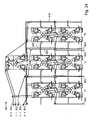
- the partial webs 3a, 3b, 3c, etc. are partially drawn through in Fig. 17 for reasons explained below (for Fig. 18), and are shown by dashed lines to another part.
- two vertically offset groups of three formers 101, 102, 103 and 106, 107, 108 are arranged according to FIG.
- this can be two each, eight-sided wide printing presses each four funnels side by side.
- an upper and a lower former 101, 106; 102, 107; 103, 108 are aligned in pairs in the above-mentioned manner to one another and to a respective center plane M.
- the three formers 101; 102; 103 and 106, respectively; 107; 108 of a group are transverse to the direction of the partial webs 03a; 03b; 03c offset from one another next to each other and arranged in an advantageous embodiment substantially at a same height. However, they may also be vertically offset from each other and / or have different vertical dimensions, but then z. B. in the horizontal plane at least partially overlap.
- the folding structure 11 Seen in the web running direction, the folding structure 11 at least in front of one of the superimposed groups of formers 101; 102; 103 and 106, respectively; 107; 108 the funnel inlet of the webs 03; 03 '; or partial webs 03a; 03b; 03c defining harp 09, ie a group of several parallel, offset in the radial direction casserole or Harfenwalzen 89; 93, over which different tracks 03; 03 'or partial webs 03a; 03b; 03c; or 03a '; 03b '; 03c 'etc. are transferred from the superstructure 04 in the folding structure 11.
- the harp rollers 89; 93 one Harp 09 are mutually vertically and / or horizontally offset and preferably stored as a unit in a common frame.
- a harp 09 may be provided for each of the vertically offset groups of formers 101; 102; 103 and 106, respectively; 107; 108 such a harp 09 may be provided.
- the harp 09 advantageously comprises at least (n * m / 2) harp rollers 88; 89; 93, whose axes of rotation z. B. are substantially in a common plane, and which are preferably stored in a common frame.
- two tracks 03; 03 '(or two printing towers 01) are at least six harp rollers 88; 89; 93 per harp 09 of advantage.
- harp rollers 88, 89, 93 are arranged per harp 09.
- a product with a total thickness of, for example, 72 pages can then be produced in the collective operation.
- a printing machine with z. B two sections of two printing towers 01 and a total of four provided for the two-sided four-color printing six printed pages wide webs 03; 03 '; 03 ", at least six harp rollers 88, 89, 93 are arranged per harp 09 of a section
- These six harp rollers 88, 89, 93 per section, here twelve, can be arranged in two structurally separate harps 09, eg over a common folding structure 11 or two Falz admittedten 11, but also in a structurally common harp 09 z.
- In two alignments may be arranged Printing machine with two sections or a total of four printing towers 01 (four tracks 03, 03 ') is then in the collective operation a product with a total strength of z.
- a printing press with z. B. two sections of two printing towers 01 and a total of four provided for the two-sided four-color printing six printed pages wide webs 03; 03 '; 03 ", at least six harp rollers 88, 89, 93 are arranged per harp 09 of a section
- These six harp rollers 88, 89, 93 per section, here twelve, can be arranged in two structurally separate harps 09, eg over a common folding structure 11 or two folding structures 11, but also in a structurally common harp 09 eg in two alignments be
- this printing press with two sections or a total of four printing towers 01 (four tracks 03, 03 ') is then in the collecting a product with a Total thickness of eg 96 pages can be generated.
- the number of harp rollers required is 89; 93 according to the configuration of the two sections. If the folding structure 11 is arranged between these two sections, then either all the harp rollers 89; 93 in an escape or to save height the harp rollers 89; 93 of each section each arranged in alignment and the alignment with each other in the radial direction offset horizontally.
- the harp rollers 89; 93 of the two escapes are here z. B. again arranged in a common frame.
- At least one of the partial webs 03a; 03b, 03c, etc., which are in front of the upper former 101; 102; 103 arranged common harp 09 passes through, on the lower former 106; 107; 108 feasible or guided.
- the partial webs 03a; 03b; 03c etc. are more or less of the partial webs 03a; 03b; 03c etc. on the upper and lower former 101; 102; 103 and 106, respectively; 107; 108 to convict.
- different strands 109; 111; 112; 113; 114; 116 on the respective lower and upper former 101; 102; 103 and 106, respectively; 107; 108 will be given.
- the aforementioned folding structure 11 with only one harp 09 for two superposed formers 101; 102; 103; 106; 107; 108 is also suitable for other printing machines with different cylinder widths and cylinder circumferences.
- One such, from two stacked formers 101; 102; 103; 106; 107; 108 and a common harp 09 existing Falzoberbau 11 may also be arranged on a third former with its own harp 09.
- the described folding structure 11 with a plurality of vertically offset formers 101; 102; 103; 106; 107; 108 assigned harp 09 is also on three superposed formers 101; 102; 103; 106; 107; 108 well applicable.
- Outside pages, for example, of an outer book can thus be assigned to a specific web guide and / or a specific printing tower / printing unit.
- upstream tension hammers 117 and hopper inlet rollers 118, as well as tension rollers 121 (FIG. 19) provided in the hemming structure 11, each have their own drive motors 119.
- the tension roller 117 for the lower group of the former 106; 107; 108 not visible.
- the respective drive motor 119 of the draw rollers 121 is shown in FIG. 19 merely by filling the respective draw roller 121.
- Each of the formers 101; 102; 103; 106; 107; 108 is at least one such driven in an advantageous embodiment Wegwalze 121 downstream, which with pressure rollers or a pressure roller on the strand 109; 111; 112; 113; 114; 116 cooperates.
- the folding structure 11 preferably has non-driven guide rollers 122, via which the one printing side wide strands 109; 111; 112; 113; 114; 116 can be performed.
- the folder 12 at least one own, of the printing units 02 mechanically independent drive motor 120.
- the drive motors 119 of the tractor inlet rollers 117; 118; 121 of the folding structure 11 and / or driven tension rollers 81 of the superstructure 04 only have to be controlled in terms of speed (with regard to an angular position)
- the drive motor 120 is designed to be adjustable or regulated with respect to its angular position on the folding apparatus 12 in an advantageous embodiment.
- the mechanically independently driven printing units 02 and the folding apparatus 12 (or their drive motors 61, 120) to specify an angular position with respect to a virtual electronic master axis.
- for. B. determines the angular position of the folder 12 (or its drive motor 120) and based on this, the relative angular position of the printing units 02 and 13 printing units specified for this.
- the z. B. only with respect to their speed controlled drive motors 80; 119 of the driven rollers 81; 117; 118 receive their speed specification, for example, from the machine control.
- the respective page numbers have to be doubled.
- the dimensioning of the cylinder 16; 17; 18 and the groups of formers 101; 102; 103; 106; 107; 108 is to be applied to each "lying" printed pages, wherein in the circumferential direction or direction of the web 03; 03 '; 03a; 03b; 03c is a section A; B; C has two lying print pages, the form cylinder 16 then z. B. has a scope corresponding to four horizontal printed pages in tabloid format.
- the number of printed pages in the longitudinal direction remains per web 03; 03 '; 03a; 03b; 03c and cylinder 16; 17; 18 or funnel width exist.
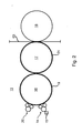
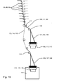
- the folder 12 with a transport cylinder 123, z. B. collecting and / or folding blade, executed, which has a circumference for receiving more than five circumferentially successively arranged section lengths and a corresponding number of holding devices 129.
- the folding apparatus 12 are u.a. three strands 109; 111; 112; 113; 114; 116 of three juxtaposed formers 101; 102; 103; 106; 107; 108 fed simultaneously.
- the folder can also be up to six strands 109; 111; 112; 113; 114; 116 are supplied from different funnel groups, which are then processed into a product.
- the transport cylinder 123 is designed with an above-mentioned large circumference, so that correspondingly large positioning movements (cutting, holding, folding) at high Safely ensure production speeds.
- the increased radius of curvature reduces the pronounced oblique cut edge of the cross-cut product, especially in the case of strong products.
- the folding apparatus 12 has at least one inlet, here two inlets, for one or more strands 109; 111; 112; 113; 114; 116 on.
- the strand 109; 111; 112; 113; 114; 116 passes through a train roller pair 124 for adjusting the voltage and strikes the transport cylinder 123 at the level of a cutting gap 126 between the transport cylinder 123 on the one hand and a cutting cylinder 127 'on the other.
- a train roller pair 124 for adjusting the voltage and strikes the transport cylinder 123 at the level of a cutting gap 126 between the transport cylinder 123 on the one hand and a cutting cylinder 127 'on the other.
- one, three or more may also be provided.
- d. H. at the location of the needling of the strand bundle immediately before the cutting gap 126 at least one pressure roller arranged as an abutment. This has, for example, circumferential, corresponding to the arrangement of the needles in the axial direction of grooves in which the puncturing needles can penetrate after passing through the strand bundle / the strand.
- Cutting the strand 109; 111; 112; 113; 114; 116 or strand bundle takes place in the cutting gap 126 between the cutting and transport cylinder 127 ': 123 by at least one cutting blade 128 of the cutting cylinder 127', which cooperates, for example, with a corresponding, not shown cutting bar on the transport cylinder 123 as an abutment.
- the folding apparatus 12 may, in an advantageous embodiment, have a device (not shown) for shortening the effective circumferential section length.
- a device for shortening the effective circumferential section length.
- the transport cylinder 123 in the region of its circumference between two transport devices 129 not shown, optionally in the radial direction out of the peripheral surface of the transport cylinder out and back into movable Verdrängerance which upon exiting the peripheral surface effective shortening of Signature with respect to the scope or effective enlargement of the distance between two causes.
- the transport cylinder 123 has on its circumference in a region which is covered by accommodated product sections, a recess or depression (eg a groove or groove), into which a received product section by a corresponding projection (eg Strip or noses) on the circumference of the cutting cylinder 127 can be pressed.
- a recess or depression eg a groove or groove
- a corresponding projection eg Strip or noses
- the location of the activated, i. in operative position device for shortening takes place advantageously within a section length following the cutting gap 126 (viewed in the direction of rotation).
- the circumference of the transport cylinder 123 corresponds to seven section lengths or seven lengths of the signature ("seven-field transport cylinder 123").
- the holding devices 129 can also be designed as a gripper 129 (gripper folder).
- seven cutting bars are arranged, which are preferably arranged in the direction of rotation each slightly (for example, 0.3 to 3 cm) to location of the nip (Greiferfalzapparat) or the NOTEur manstich (Punkturfalapparat) spaced on the lateral surface of the transport cylinder 123.
- the circumference of the jaw cylinder 132 also preferably corresponds to more than five, in particular seven, section lengths or seven lengths of the signature.
- the strand 109; 111; 112; 113; 114; 116 truncated signature is further promoted by the holding device 129 on the transport cylinder 123.
- the transport cylinder 123 On the transport cylinder 123 further seven folding blades 130 are mounted, which are each extended on reaching a gap 131 (depending on the collection or normal operation each or every multiple times) between the transport cylinder 123 and a jaw cylinder 132 to the transported on the transport cylinder 123 signatures to the Hand over jaw cylinder 132 and fold.
- the Jaw cylinder 132 circumferentially evenly spaced z. B. as many jaws (not shown) on how the number of folding blades 130 and / or the holding devices 129 on the transport cylinder 123, in particular seven.
- the folded products are transferred from the jaw cylinder 132 to a paddle wheel 133 and from there to a delivery device 134, z. B. a conveyor belt 134 designed.
- the folding apparatus 12, or its transport cylinder 123 is designed so that it can be switched between a mode for a normal and a collective mode optionally.
- the signature product section
- the first signature bearing holding means 129 at least one more signature before the so-collected signatures are delivered together in the gap 131 to the jaw cylinder 132.
- the transport cylinder 123 transmits the signature each time the first passage of the gap 131 to the next cylinder 132.
- the transport cylinder 123 is preferably implemented in a convertible execution as Cincinnatiurzylinder 123, in particular with seven NOTEurologyn 129 in the circumference.
- Cutting 127 ', transport 123, jaw cylinder 132 and possibly paddle 133 are preferably driven by at least one drive motor (shown schematically in Fig. 19 drive motor 120) mechanically independent of printing units 03, superstructure 04 and folding structure 11.
- the drive is advantageously via a transmission, in particular a reduction gear, from the drive motor to one or more of the cylinder 123; 127 '; 132 of the folding apparatus 12th
- the drive motor via an unillustrated transmission (eg., Unmentioned pinion or drive wheels) on the Cutting cylinder 127 'driven.
- the latter is driven onto the transport cylinder 123 and from there to the jaw cylinder 132.
- From the jaw cylinder 132 is driven here via a belt drive 137 to the paddle wheel 133.
- the drive motor is driven by a pinion 138 or drive wheel 138 (dashed) onto the transport cylinder 123.
- the latter is driven onto the cutting cylinder 127 'and the jaw cylinder 132.
- the delivery device 134 preferably has its own, from the cylinders 123, 127 '; 132 and the paddle wheel 133 mechanically independent drive motor.
- Cutting 127 ', transport 123 and jaw cylinder 132 may also be mechanically independent of each other and driven by the printing units by their own drive motors.
- cutting 127 ', transport 123 and jaw cylinder 132 are driven by at least one common or alternatively by one of the printing units mechanically independent drive motor, while in a first variant paddle wheel 133 and delivery device 134 by a common drive motor mechanically independent from the cylinders 923; 127 '; 132 and the printing units and in a second variant are each driven in rotation by their own drive motors.
- a possibly provided band system for guiding the product sections into and through the folding apparatus 12 can also be mechanically independent of the cylinders 123; 127 '; 132 be driven.
- the transport cylinder 123 With the execution of the transport cylinder 123 with seven Abschnütsinn on the circumference it is from o.g. Possible reasons, twelve tracks 03 and the corresponding number of partial tracks 03a; 03b; 03c etc. (up to seventy-two paper layers), divided into up to six strands 109; 111; 112; 113; 114; 116 to lead to the folder 12.
- This can be by means of a folder 12 without collecting a product with z. B. a total of 144 pages, especially newspaper pages produce.
- the folder 12 executed for the collective operation so can be by means of six webs 03, the product of z. B. 144 pages or more tracks 03 even higher page numbers produce.
- the folder 12 is designed, for example, as a wheel rebate, or else the holding devices 129 and the jaws have to be designed to accommodate such a large number of layers.
- one pair of draw rollers 124 or several pairs of draw rollers 124 each have at least one own drive motor 139.
- a plurality of strands 109; 111; 112; 113; 114; 116 are summarized.
- the folding apparatus 12 has a cutting cylinder 127 'with four cutting blades 128 in the circumferential direction (FIG. 20).
- the circumference of the cutting cylinder 127 ' substantially corresponds to four section lengths of the product to be cut. With one revolution, four cuts are made through the four knives 128 arranged one behind the other in the circumferential direction.
- the four knives 128 can advantageously be spaced alternately 90 ° - ⁇ and 90 ° + ⁇ apart from one another in an equidistant arrangement, where ⁇ represents a small angle (for example less than 2 °, in particular less than 1 °).
- the longer and the shorter should differ from the middle section length by about 1 to 5, in particular 1.5 to 3.5 mm, d. H. two consecutive sections differ in length by a total of 3 to 7 mm.
- two or more strands or strands 135 may be combined prior to entry into the cutting gap 126 via a roller or roller pair 125 - driven by a motor (as a pull group 125) or as a non-driven (guide roller).
- a motor as a pull group 125
- a non-driven (guide roller) guide roller
- Fig. 20 has been omitted for simplicity on the detailed presentation of the rest of the conveyor system (drive motor, driven train group, etc.) and the drive motor including drive train.
- the circumference corresponds to four (average) lengths of the tracks 03; 04 to be produced signatures.
- the cutting blades 128 are not arranged equidistant on the circumference of the cutting cylinder 127 ', but it alternates an angular segment slightly larger than 90 ° and a slightly smaller 90 ° at the periphery.
- the cutting cylinder 127 'with four-circumference is therefore particularly advantageous in the above-described printing machine with three-width printing units 02 and / or arranged together with a seven-field transport cylinder 123 because of the possibility of cutting strands of large product thicknesses.
- the four-circumference design is also applicable to any web press and / or co-operative with multi-field (eg, five or seven) transfer cylinders of other formats to increase accuracy and / or product strength.
- the quadruple cutting cylinder 127 'leads to a smaller tilt of the cutting blade 128 when hitting a cutting bar on the transport cylinder and there possibly provided slot rubber, which also requires a lower cutting power (energy or force) than when double cutting cylinder. Grooving and dewatering of the knife into the grooved rubber takes place at a considerably smaller angle of inclination of the cutting knife 128. Both the bending and the pressing load of the cutting knife 128 are lower overall than with the double cutting cylinder.
- FIG. 21 Also shown in Fig. 21 is an advantageous embodiment of the folding apparatus 12 - as a supplement to the execution with quadruple cutting cylinder 127 'and / or 7-fold transport cylinder 123 or viewed individually - with a pressing device 143 shown.
- a pressing element 143 allows for a better and trouble-free needling of the product sections to be accommodated by puncturing needles 144 (the holding device 129) of the transporting cylinder 123.
- the bending stress of the point needles 144 (in short, needles 144) is reduced and / or the risk of bursting and stripping of the product sections during the puncture is reduced.
- the pressure cylinder 143 for this purpose in different ways.
- the lateral surface corresponding to the axial position of the needles 144 in the circumferential direction have circumferential grooves or recesses.
- the lateral surface instead or in addition to this compliant material -.
- foam - have, which yields at the puncture of the needles 144 at the point concerned, the strand aufausadelnden 135 but otherwise supports.
- the pressure cylinder 143 or the pressing elements 146 has or show in an advantageous embodiment complementary to each other in mutual settlement of Andschreib- and transport cylinder 143; 123 resulting pattern of the extended needles 144 on a group of recesses 147, in particular holes 147, for receiving the needles 144 on.
- the interaction of needles 144 and the holes 147 of the pressing members 146 is shown schematically.
- Over the length of the Andrückzylinders 143 can either be designed as a strip pressure element 146 with multiple holes 147 or it can be arranged in the axial direction next to each other several pressing element 146, each with one or more holes 147, wherein the group of holes 146 in all cases as above are arranged to be arranged complementary to the arrangement of the needles 144.
- the pressure cylinder 143 preferably has a circumference which corresponds to an integer multiple of a section length of the product section. If the circumference of a section length corresponds to a group of above-described, axially spaced holes 144 is provided in cross-section. In a two section lengths corresponding circumference two circumferentially equidistant spaced groups of holes 146 are provided.
- the puncturing needles 144 are prior to the puncture z. B. extended completely out of the transport cylinder 123, so that no additional acceleration forces acting on a movement of the puncture strips 129 causing puncture cam. It can be used in cross-section reinforced puncturing needles 144 to increase the stability.
- the strand 135 or strand bundle runs onto the transport cylinder 123 before the beginning of the puncture by the needles 144.
- the application of the pressure element 146 preferably takes place after the strand 135 has run onto the transport cylinder 123 but before the beginning of the puncture by the needles 144 instead.
- the piercing and puncturing the puncturing needles 144 takes place against these pressing elements 146th
- a lifting of the pressing elements from the strand or from the paper strands takes place after completion of the needling. This is supported for example by the radially outwardly directed resilient mounting of the pressing elements.
- the pressing elements in an advantageous embodiment at the site of the puncture of the puncturing needles 144 holes 147 on. These are z. B. with a slightly larger diameter than the point needles 144 itself.
- the holes 147 are z. B. tapered from the rear, on the one hand not to hinder the relative tilting of the puncturing needles 144 during the passage and on the other hand still prevent the paper at the puncture needle puncture at bursting through a narrow hole 147.
- scraper elements may be provided to aid in the stripping of the paper as the punctures ebb.
- This can be z. B. by modification in the construction of the spud strip 129 and their movement dergestalt be done so that instead of pivoting NOTEurhalter as well as in Räderfalztechniken linearly moving point needles 144 are used.
- the holes 147 in the cylinder body of the pressure-applying cylinder 143 for penetrating the needles 144 can be made small enough to effectively assist in stripping.
- the pressure cylinder 143 without specially spring-mounted pressure elements 146.
- the holes 147 may be arranged directly in the lateral surface of the Andrückzylinders 143. They are then again complementary to each other in mutual settlement of Andschreib- and transport cylinder 143; 123 resulting pattern of the extended needles 144 arranged.
- the pressure cylinder 143 may be mounted resiliently in total against the transport cylinder 123, wherein a minimum torque by possibly existing looping and / or the pulse during penetration of the strand 135 are taken into account got to.
- the measures mentioned - seven times transport cylinder 123, fourfold cutting cylinder 127 ', pressure cylinder 143 - on the folding apparatus 12 are basically each individually considered individually, but also in particular in explicit combination of several or all measures particularly advantageous versions of the folder This is generally true for various types of press, but particularly to a press having one or more of the above-described aggregates for printing six juxtaposed newspaper pages.
- the additional printing units 151 or printing areas are preferably designed corresponding to the printing units 02 as printing units 151 for the indirect planographic printing, d. H. they have between printing point and forme cylinder 16 to a transfer cylinder 17.
- a printing tower T1; T2; T3 is associated with at least one additional printing unit 152 (additional printing unit 152) with at least one further printing group 151, ie with at least one printing location.
- the printing tower T1; T2; T3 but at least two pressure points in one or two printing units 151, assigned, which are arranged in a common additional pressure unit 152 or in separate additional pressure units 152.
- These additional pressure points are advantageously above the pressure points of the printing tower T1; T2; T3.
- the printing tower T1; T2; T3 preferably has a total of eight pressure points through which z. B.
- the printing units 02 of the printing tower T1; T2; T3 are arranged vertically above one another and are preferably designed as satellite printing units 02.
- At least two satellite printing units 02 are additionally two pressure points, z. B. as two three-cylinder printing units 151, assigned, by means of which, for example, two each one-sided in the at least one printing tower T1; T2; T3 printed webs B10; B20; B30; B40 on its other side are monochrome printable.
- the two satellite printing units 02 are associated with each other and components of a printing tower T1; T2; T3 by means of which optionally two tracks B10; B20; B30; B40 each one-sided multicolored or a web B10; B20; B30; B40 are double-sided printable or is.
- the two satellite printing units 02 are stacked on top of each other. They are preferably designed in each case as nine-cylinder satellite pressure units 02.
- a three-cylinder printing unit 151 has a cylinder pair of mold 16 and transfer cylinder 17 and a cooperating with one of the transfer cylinders 17 impression cylinder 126.
- the two three-cylinder printing units 151 are advantageous (space, assembly) together as a six-cylinder printing unit 152 executed, but may also be formed in each case as a single units. It is also possible that only one pressure point in the form of, for example, a three-cylinder printing unit 151 above the printing tower T1; T2; T3 is provided.
- the two three-cylinder printing units 151 are arranged above a last printing location of the two associated satellite printing units 02.
- the six-cylinder printing unit 152 is z. B. on the associated printing tower T1; T2; T3 stacked arranged.
- it can - depending on the production - on a railway technically associated printing tower T1; T2; T3 different, in particular adjacent, printing tower T1; T2; T3 be stacked.
- the satellite printing units 02 and the two three-cylinder printing 151 are assigned to each other in the sense (railway technology) that a web either in a first mode of operation by both satellite printing units 02, in a second mode by one of the satellite printing units 02 and one of the three-cylinder printing units 151, and in a third mode of operation is performed only by the two three-cylinder printing 151.
- the satellite printing units 02 and the two three-cylinder printing units 151 are also associated with each other in the sense that in a first mode of operation, a first path through both satellite printing units 02 and a second path through the two three-cylinder printing units 151, and in a second mode two lanes each by one of the satellite printing units 02 and by one of the three-cylinder printing units 151, are guided.
- Two tracks are z. B. in the way by the printing tower T1; T2; T3 and the six-cylinder printing unit 152 led that they are printed after printing on one side multi-colored and on the other side monochrome.
- One of two lanes is z. B. by the printing tower T1; T2; T3 and another web is guided only by the six-cylinder printing unit 152 in such a way that the one web is multicolored on both sides and the other web both sides monochrome (S-guide) or one-sided bicolour (C-guide, not shown) is printed.
- At least the printing press has a plurality of printing towers T1 each having two satellite printing units 02; T2; T3 and additionally at least a six-cylinder printing unit 152.
- the printing machine has z. B. at least two, in particular at least three, mutually adjacent printing towers T1; T2; T3, wherein the at least one six-cylinder printing unit 152 on one of the two, in particular three printing towers T1; T2; T3 is stacked.
- no other processing stage in particular no folding structure and / or folding apparatus, is arranged between the respective printing towers associated with one another in the aforesaid manner.
- the further printing units 151 are arranged above the printing units 13 of the printing units 02. They are advantageous on one of the printing towers T1; T2; T3 is stacked.
- the printing press comprises (at least) three printing towers T1 adjacent to one another in pairs; T2; T3, wherein the at least one six-cylinder printing unit 152 on one of the three printing towers T1; T2; T3 is stacked.
- the three printing towers T1; T2; T3 is associated with a common six-cylinder printing unit 152, which preferably on the middle of the three printing towers T1; T2; T3 is stacked.
- Three tracks are z. B. in the way by at least two of the towers T1; T2; T3 and the six-cylinder printing unit 152 performed that two of the webs after printing on each side of multi-colored and on the other side monochrome, and the third web are printed on both sides multi-colored ( Figures 25, 26, 27).
- Two of the three webs are in alternate web routing through at least two of the towers T1; T2; T3 and a third lane is guided only by the six-cylinder printing unit 152 in such a way that the first two webs are printed on both sides multicolor and the third web both sides monochrome (or one-sided bicolor) (Fig. 23, 24).
- the printing machine advantageously has means 153 (deflection rollers 153 and / or retraction paths, not shown) for guiding the webs, which can be operated selectively allows the printing machine in this and the aforementioned productions (only exemplified in Fig. 25).
- deflecting rollers 153 are provided which guide a web B10; B20; B30; B30 in the additional printing unit 151 allows, which was previously printed in an adjacent satellite printing unit 02, and not in the directly below it.
- the printing units 151 tracks B10; B20; B30; B30 this previously in the two satellite printing units 02 of the same printing tower T1; T2; T3 printed (FIG. 25: left, FIG. 26: middle, FIG. 27: right).
- the printing machine advantageously has o.g. Means 153 for guiding the webs, which allows an optional operation of the printing press according to the two (or three) said modes.
- the two on one side more and on the other side printed on one side pass through this z.
- the four lanes with the three towers T1; T2; T3 and the six-cylinder printing unit 152 printed in such a way that the two more on one side and on the other side printed on one side webs after printing on a way to a hopper TR above the two sides of both multicolored printed webs come to rest (Fig 25).
- the two on one side more and on the other side printed on one side pass through the webs of the three towers T1 remote from the funnel structure TR; T2; T3 and the six-cylinder printing unit 152.
- the printing machine preferably has means 153 for guiding the webs, which allows an optional operation of the printing press according to the last three modes of operation.
- the satellite printing unit has a plurality of, in particular four, pairs of cylinders each of form 16 and transfer cylinder 17, and at least one cooperating with at least one of the transfer cylinder 17 satellite cylinder 18. It is advantageous four Paired with a satellite cylinder 18 assigned. But there may also be two satellite cylinders 18 to the four pairs.
- each case two of the pairs are driven as drive composites by a common drive motor 61 which is independent of the respective other drive network.
- the satellite cylinder 18 (or either one of two) is powered by one of the drive assemblies.
- the satellite cylinder 18 is driven by at least one own drive motor 61, independent of the pairs.
- each cylinder of the pair may have its own drive motor 61.
- the two cylinders of the pair are coupled and driven by a common drive motor 61.
- An inking unit 14 is driven in a less expensive design by the drive of the associated forme cylinder 16 ago. However, it can also be driven independently of the drive of the associated forme cylinder 16 by its own drive motor 61.
- the additional printing unit 151 has a cylinder pair of mold 16 and transfer cylinder 17, and a cooperating with one of the transfer cylinder 17 printing or impression cylinder 18. The same goes for one second envisaged printing unit 151.
- the reference numerals used here were those of the printing units 02, since in the exemplary embodiment shown, this is likewise an indirect lithographic printing method with the corresponding functionality of the cylinders 16; 17; 18 acts.
- the six-cylinder printing unit 152 has two pairs of cylinders each of mold 16 and transfer cylinder 17, and each pair on one of the transfer cylinder 17 cooperating impression cylinder.
- the pair or pairs (of the printing units 151 and the six-cylinder printing unit 152) is or are driven in a preferred embodiment in each case by at least one own drive motor 61 independently of the other pair.
- each cylinder of the pairs have their own drive motor 61.
- the two cylinders of the pair are coupled and driven by a common drive motor 61, independently of the other pair of cylinders.
- An inking unit 14 is driven in a less expensive design by the drive of the associated forme cylinder 16 ago. However, it can also be driven independently of the drive of the associated forme cylinder 16 by its own drive motor 61.
- the impression cylinders are driven in an advantageous embodiment, each by its own drive motor 61, regardless of the pairs and each other. This is advantageous in view of the independent positioning of the two printing units.
- the two impression cylinders may be driven by at least one common drive motor 61, independently of the pairs.
- the counter-pressure cylinders can each be driven by the associated pair.
- the cylinders of the pairs are each driven in pairs by a respective drive motor 61 and the impression cylinders individually by a respective drive motor 61.
- a printed product (or web strand) can be produced, so that of four after the printing on the way to funnel inlet adjacent tracks two tracks each on one side multicolor, in particular four-color, and on the other side monochrome, and the other two tracks printed on both sides multicolored, in particular four-color:
- bottom web 1 4 (bottom one color: top four colors), second bottom web 4: 1, third bottom bottom 4: 4 and fourth Track 4: 4.
- bottom web 4 4 (bottom one color: top four colors)
- second bottom web 1 4 third bottom web 4: 1
- fourth web 4 4.
- bottom web 4 4 (bottom one color: top four colors)
- second bottom web 1 4 third bottom web 4: 1
- fourth web 4 4.
- a printed product can be produced, so that of four after printing on the way to the funnel inlet adjacent tracks three lanes on both sides multi-colored, especially four-color, and the fourth web are printed on both sides monochrome:
- bottom web 4 4 (bottom one color: top four colors), second bottom web 1: 1, third bottom bottom 4: 4 and fourth Track 4: 4.
- a first printed product / strand of four webs viewed from bottom to top with the following color: bottom web 4: 4 (bottom one color: top four colors), second bottom web 4: 4 third bottom web 1: 1 and fourth Track 4: 4.
- the described embodiment of the printing press in particular with the six-cylinder printing unit 152, allows the described variety in production, without the need for reversible printing units would be required.
- the cylinders of the satellite printing units 02 and the six-cylinder printing unit 152 can always be operated in the same direction of rotation. This provides advantages in terms of using Minigap technology, i. H. the narrow opening 28, and in terms of effort in equipment and drive.
- the printing machine is z. B. with printing units, which have a width of six widths of stationary printed pages, especially in the newspaper format.
- the circumference of at least the forme cylinder 16 substantially corresponds to the length of two lengths of two printed pages, especially in the newspaper format.
Abstract
Description
Die Erfindung betrifft eine Rollenrotationsdruckmaschine gemäß dem Oberbegriff des Anspruchs 1.The invention relates to a web-fed rotary printing press according to the preamble of
In der
"Offsetdrucktechnik" von H. Teschner, Fachschriftenverlag GmbH & Co. KG, 1995, offenbart auf Seite 10/32 in Figur 6 eine Neunzylinder-Satellitendruckeinheit, auf welcher ein Drei-Zylinder-Colordeck für den 4/1-Druck angeordnet ist."Offset Printing Technology" by H. Teschner, Fachschriftenverlag GmbH & Co. KG, 1995, discloses on page 10/32 in Figure 6 a nine-cylinder satellite printing unit on which a three-cylinder color deck for the 4/1 print is arranged.
Die
Auch die
Durch die
Durch die
Aus "Newspapers & Technology", December 2000, ist eine Druckmaschine mit sechs Zeitungsseiten breiten Druckwerken bekannt. Die Druckwerke sind als Brückendruckwerke ausgebildet, wobei die Übertragungszylinder mit Gummituchhülsen belegt sind.From "Newspapers & Technology", December 2000, a printing press with six newspaper-wide printing units is known. The printing units are designed as bridge printing units, wherein the transfer cylinders are covered with blanket sleeves.
Die
Aus der
Durch die
In der
Die
Durch die
Aus der
Die
In der
Durch die
Der Erfindung liegt die Aufgabe zugrunde, eine Rollenrotationsdruckmaschine zu schaffen.The invention has for its object to provide a web-fed rotary printing press.
Die Aufgabe wird erfindungsgemäß durch die Merkmale des Anspruchs 1 gelöst.The object is achieved by the features of
Die mit der Erfindung erzielbaren Vorteile bestehen insbesondere darin, dass eine Rollenrotationsdruckmaschine mit einem Falzapparat für einen hohen Ausstoß, insbesondere zusammen mit einer dreifach breiten Druckmaschine, bei sicherem Betrieb geschaffen ist.The achievable with the present invention consist in particular in that a web-fed rotary printing press with a folder for high output, especially together with a triple wide printing machine, is created in safe operation.
Vorteilhaft ist ein Transportzylinder mit einem großen Umfang ausgeführt, um damit entsprechend große Stellbewegungen (Schneiden, Halten, Falzen) bei hohen Produktionsgeschwindigkeiten sicher zu gewährleisten. Zum anderen vermindert der vergrößerte Krümmungsradius die insbesondere bei starken Produkten ausgeprägte schräge Schnittkante des quer geschnittenen Produktes.Advantageously, a transport cylinder is designed with a large circumference in order to ensure accordingly large positioning movements (cutting, holding, folding) at high production speeds safely. On the other hand, the increased radius of curvature reduces the pronounced oblique cut edge of the cross-cut product, especially in the case of strong products.
In einer vorteilhaften Ausführung weist der Falzapparat einen Schneidzylinder mit vier Schneidmessern in Umfangsrichtung auf, d. h. er weist eine 4-fachen Umfang einer Abschnittlänge auf. Von großem Vorteil - insbesondere im Zusammenhang mit den o.g. Druckmaschinen - wirkt der 4-fache Schneidzylinder und/oder das Andrückelement (z. B. Andrückwalze) mit einem 7-teiligem Transportzylinder zusammen. Dieser ist für Ausführungen des Falzapparates mit 4-teiligem Schneidzylinder grundsätzlich entweder als Punkturzylinder oder als Greiferzylinder ausgeführt.In an advantageous embodiment, the folder on a cutting cylinder with four cutting blades in the circumferential direction, d. H. he has a 4-fold extent of a section length. Of great advantage - especially in connection with the o.g. Printing machines - the 4-fold cutting cylinder and / or the pressure element (eg pressure roller) interacts with a 7-piece transport cylinder. This is designed for executions of the folder with 4-piece cutting cylinder basically either as Punkturzylinder or as a gripper cylinder.
Mit der vorteilhaften Ausbildung des Schneidzylinders mit vier am Umfang hintereinander angeordneten Messern werden gegenüber einem 2-fachen Schneidzylinder geometrisch bedingt deutlich verringerter Kippbewegung des Messers in den Nutleisten verursacht. Der vier Schneidmesser bzw. vier Abschnittlängen (Signaturen) am Umfang aufweisende Schneidzylinder ("Schneidzylinder mit Vierfachumfang") ermöglicht den Einsatz erheblich stärkerer Lager, eine größere Zapfenstärke und/oder eine stärkere Bauweise des Zylinderkörpers selbst, was zur Erhöhung der Stabilität beiträgt. Es können hiermit stärkere Produkte (mehr Lagen) geschnitten werden, da eine höhere Kraft aufbringbar ist. Für kleinere Produktstärken kann sich durch die Verwindungs- und/oder Durchbiegungsarmut die Schneidgenauigkeit erhöhen.With the advantageous embodiment of the cutting cylinder with four knives arranged circumferentially one behind the other, a geometrically conditioned significantly reduced tilting movement of the knife in the groove strips is caused by comparison with a 2-fold cutting cylinder. The four cutting blades or four section lengths (signatures) on the circumference having cutting cylinder ("four-circumference cutting cylinder") allows the use of significantly stronger bearings, a larger pin thickness and / or a stronger construction of the cylinder body itself, which contributes to increasing the stability. It can hereby stronger products (more layers) are cut because a higher force can be applied. For smaller product thicknesses may be due to the twisting and / or Low deflection increase the cutting accuracy.
In einer anderen vorteilhaften Ausführung oder einer Weiterbildung o.g. Ausführung weist der Falzapparat ein Andrückelement, insbesondere einen Andrückzylinder, auf, welcher den Punkturnadeln beim aufnadeln eines Strang (bzw. Strangbündel) als Widerlager dient. Der Einsatz des Andrückelementes ist i.V.m. einem als Punkturzylinder ausgeführtem Transportzylinder von besonderem Vorteil.In another advantageous embodiment or a development o.g. The folding apparatus has a pressure element, in particular a pressure cylinder, which serves the point needles when needling a strand (or strand bundle) as an abutment. The use of the pressure element is i.V.m. a running as Punkturzylinder transport cylinder of particular advantage.
In einer vorteilhaften Ausführung ist der Falzapparat dazu ausgebildet, wahlweise in einem Sammelbetrieb - Aufnahme mehrerer Produktabschnitte übereinander auf dem Transportzylinder während mehr als einer Umdrehung bevor eine Abgabe dieser gestapelten Lagen an den folgenden Zylinder, insbesondere Falzklappenzylinder, erfolgt - und im Nichtsammelbetrieb - Abgabe des Produktabschnittes beim ersten Durchlaufen der Nippstelle zwischen Transport- und Falzklappenzylinder - betrieben zu werden.In an advantageous embodiment of the folder is designed to selectively in a collective mode - recording several product sections one above the other on the transport cylinder during more than one revolution before a delivery of these stacked layers to the following cylinder, in particular jaw cylinder takes place - and in non-collection mode - delivery of the product section to be operated during the first passage through the nip between the transport and jaw cylinders.
Die vorgenannten Ausführungen des Falzapparates sind besonders in Verbindung mit zu erzeugenden Produkten hoher Seitenzahlen von Vorteil. Eine vorteilhafte Druckmaschine weist Druckwerke mit einer Breite der Druckzylinder zum Druck von sechs nebeneinander angeordneter Zeitungsseiten und einen der o . g Falzapparate auf. Der Formzylinder des Druckwerkes weist dann eine Länge zum tragen einer oder mehrerer Druckformen mit insgesamt sechs nebeneinander angeordneten Zeitungsseiten - z.B. im BroadsheetFormat - auf. Dem Falzapparat ist hierbei beispielsweise ein Trichteraufbau mit drei quer zur Laufrichtung der Bahnen quer nebeneinander angeordnete Falztrichter vorgeordnet.The above-mentioned embodiments of the folding apparatus are particularly advantageous in connection with high-page-number products to be produced. An advantageous printing press has printing units with a width of the printing cylinder for printing six juxtaposed newspaper pages and one of the o. g folders. The forme cylinder of the printing unit then has a length for carrying one or more printing forms with a total of six juxtaposed newspaper pages - e.g. in broadsheet format - on. The folder in this case, for example, a funnel structure with three transverse to the direction of the tracks arranged transversely juxtaposed former.
Ähnliche Vorteile gelten auch für eine Druckmaschine, in welcher eine Vielzahl, z.B. sechs oder mehr Teilbahnen vor dem Falzapparat zu einem zu falzenden Strang zusammen gefasst werden. Weiter sind die Ausführungen besonders für Druckmaschinen mit hoher Produktionsgeschwindigkeit, d. h. schnell laufende Druckwerke für Papiergeschwindigkeiten von beispielsweise 12 m/s und mehr, von Vorteil.Similar advantages also apply to a printing machine in which a plurality, for example, six or more partial webs before the folder to be folded together to a fold. Furthermore, the embodiments are particularly advantageous for high-speed printing machines, ie high-speed printing units for paper speeds of, for example, 12 m / s and more.
Vorteile bestehen insbesondere auch darin, dass bei dreifach breiten Druckeinheiten im Vergleich zu einer doppeltbreiten Druckmaschine bei der selben zu erreichenden Sollstärke eines Produktes die Produktionssicherheit erheblich erhöht wird. Bei Beibehaltung der Anzahl von Druckeinheiten kann jedoch auch der Ausstoß der Druckmaschine, bzw. jedes Druckwerkes um 50% gesteigert werden.In particular, there are also advantages in that production reliability is considerably increased in the case of triple-wide printing units in comparison to a double-width printing press at the same target thickness of a product to be achieved. While maintaining the number of printing units but also the output of the printing press, or each printing unit can be increased by 50%.
Die Anzahl der Rollenwechsler (Investition), die Häufigkeit der Rollenwechsel (Produktionssicherheit) sowie die Rüstzeit beim Einziehen von Bahnen (Zykluszeiten) kann gegenüber einer doppelt breiten Druckmaschine für die selbe Produktstärke vermindert werden.The number of reelstands (investment), the frequency of reel changes (production safety) and the set-up time when webs are drawn in (cycle times) can be reduced compared to a double-width press for the same product thickness.
In vorteilhafter Ausführung sind die Druckeinheiten als Neunzylinder-Satelliten-Druckeinheiten ausgeführt, was zum einen eine hohe Präzision im Farbregister und zum anderen eine schwingungsarme Bauweise zur Folge hat. Schwingungen werden auch vermindert durch die vorteilhafte Anordnung, Ausführung und Befestigung von Aufzügen auf den Zylindern. Zum einen werden Öffnungen auf den Mantelflächen in Umfangsrichtung minimiert. Weiterhin können zumindest auf dem Übertragungszylinder die Öffnungen derart alternierend in Umfangsrichtung versetzt angeordnet sein, dass zumindest auf einer Abschnittlänge immer eine geschlossene Mantelfläche mit dem Form- bzw. Satellitenzylinder zusammen wirkt. Zum dritten werden Unrundheiten und Herstellungskosten dadurch minimiert, dass zwar den Ballen auf seiner gesamten wirksamen Länge axial durchsetzende Kanäle vorgesehen sind, Öffnungen hin zur Mantelfläche jedoch nur in den genannten Abschnitten bestehen. In die Kanäle werden dann z. B. wahlweise Vorrichtungen zur Befestigung von Aufzugenden und/oder Füllstücke eingesetzt.In an advantageous embodiment, the printing units are designed as nine-cylinder satellite printing units, which on the one hand has a high precision in the color register and on the other hand a low-vibration construction result. Vibrations are also reduced by the advantageous arrangement, design and mounting of lifts on the cylinders. On the one hand, openings on the lateral surfaces in the circumferential direction are minimized. Furthermore, at least on the transfer cylinder, the openings may be arranged alternately offset in the circumferential direction, that acts at least on a section length always a closed lateral surface with the forming or satellite cylinder together. Third, roundness and manufacturing costs are minimized by the fact that although the bales are provided on its entire effective length axially passing channels, but openings exist to the lateral surface only in the said sections. In the channels then z. B. optionally used devices for attachment of elevator ends and / or patches.
Im Kanal bzw. in den Kanälen der Formzylinder sind in axialer Richtung jeweils zumindest sechs Einrichtungen zur axialen Positionierung von Druckformen angeordnet. Diese sind z. B. als formschlüssig mit Druckformenden zusammen wirkende Registerstifte ausgeführt, welche innerhalb des Kanals manuell oder fernbetätigbar axial bewegbar angeordnet sind.In the channel or in the channels of the forme cylinder, in each case at least six devices for the axial positioning of printing plates are arranged in the axial direction. These are z. B. designed as a form-fitting with pressure forming ends cooperating register pins which are arranged axially movable manually or remotely operable within the channel.
Vorteilhaft im Hinblick auf eine register- bzw. passergenaue reproduzierbare Bestückung der Formzylinder mit Druckformen ist die Ausführung der Druckwerke mit zugeordneten Andrückvorrichtungen. Es können mit diesen auf der Mantelfläche des Zylinders aufliegende Aufzüge durch jeweils mindestens ein Andrückelement je nach Bedarf fixiert sein, während ein Ende eines Aufzugs oder mehrerer Aufzüge zur Entnahme oder zur Bestückung freigegeben ist bzw. sind.The execution of the printing units with associated pressing devices is advantageous in terms of a register-accurate or register-accurate reproducible equipping the form cylinder with printing plates. It can be fixed with these resting on the lateral surface of the cylinder lifts by at least one pressing element as needed, while one end of an elevator or more elevators for removal or assembly is released or are.
Der mechanisch von den Zylinderpaaren unabhängige Antrieb des (bzw. der) Satellitenzylinder birgt insbesondere Vorteile im Hinblick auf die Möglichkeit eines variablen Betriebs. So kann beispielsweise während der Produktion ein Rüsten, z. B. ein fliegender Druckformwechsel oder ein Waschen, erfolgen. Umgekehrt kann eine Bahn eingezogen werden, während andere Zylinder bzw. Zylinderpaare stehen oder ein Rüstprogramm durchlaufen. Auch ist es von Vorteil, bei Vorliegen von Gummitüchern mit positiv oder negativ fördernden Eigenschaften, den Satellitenzylinder mit einer von den übrigen Zylindern unterschiedlichen Oberflächengeschwindigkeit zu betreiben.The mechanically independent of the cylinder pairs drive the (or the) satellite cylinder has particular advantages in terms of the possibility of variable operation. For example, during production, a setup, z. As a flying printing form change or washing done. Conversely, a web can be retracted while other cylinders or pairs of cylinders are standing or undergoing a set-up program. Also, it is advantageous to operate in the presence of rubber blankets with positive or negative promotional properties, the satellite cylinder with a different surface speed of the other cylinders.
In vorteilhafter Ausführung weist ein Überbau der Druckmaschine zumindest eine Längsschneideeinrichtung mit zumindest fünf quer zur Papierlaufrichtung voneinander beabstandeten Messern auf. In vorteilhafter Ausführung sind je Druckturm (bzw. je acht Druckstellen) zwei quer zur Papierlaufrichtung bewegbare Registereinrichtungen zur Kompensation von Laufwegen der Teilbahnen vorgesehen. Diese können in Weiterbildung baulich mit jeweils einer teilbahnbreiten Wendeeinrichtungen verbunden sein. Auch nachfolgende, lediglich Teilbahnen zugeordnete Leitelemente sind z. B. im wesentlichen lediglich teilbahnbreit ausgeführt. Diese Ausführungen ermöglichen einen schwingungsarmen, und damit wieder passgenauen Transport der Bahn. Durch Trägheit langer, starker, lediglich durch die Teilbahn(en) getriebener Leitelemente verursachte Bahnspannungsschwankungen (bei z. B. Lastwechseln, Änderung der Druckgeschwindigkeit) können wirksam vermindert werden.In an advantageous embodiment, a superstructure of the printing press has at least one longitudinal cutting device with at least five knives spaced apart from one another transversely to the direction of travel of the paper. In an advantageous embodiment, each printing tower (or eight printing locations) is provided with two register devices movable transversely to the direction of travel of the paper to compensate for paths of the partial webs. These can be structurally connected in each case with a part-web-wide turning devices. Also subsequent, only partial webs associated guide elements are z. B. executed essentially only partial web width substantially. These designs allow a low-vibration, and thus tailor-made transport of the web. By inertia Long, strong, caused only by the sub-orbit (s) guide elements caused web tension fluctuations (for example, load changes, change in printing speed) can be effectively reduced.
Im Hinblick auf einen zuverlässigen Betrieb und eine kostensparende Bauweise ist es auch von Vorteil, im Überbau die Möglichkeit einer Wendung einer Teilbahn um ein ungeradzahliges Vielfaches einer halben Teilbahn vorzusehen. Damit kann ein Einziehen und Bedrucken von Teilbahnen mit einer halben Trichterbreite (z. B. einer Zeitungsseite) entfallen.With regard to a reliable operation and a cost-saving design, it is also advantageous to provide in the superstructure the possibility of turning a partial web by an odd multiple of half a partial web. Thus, a retraction and printing of partial webs with half a funnel width (eg a newspaper page) can be omitted.
In Bezug auf Kosten und raumsparende Bauweise ist es in einer Ausführung von Vorteil, lediglich einem von zwei übereinander angeordneten Falztrichtern eine sog. Harfe, d. h. mehrere i. d. R. ungetriebene Auflaufwalzen, vorzuordnen. Auf den anderen Falztrichter sind Bahnen aus der Harfe überführbar. Den beiden vertikal übereinander angeordneten Falztrichtern sind aus der selben Flucht von übereinander liegenden Teilbahnen Stränge variabler Stärke bzw. Teilbahnanzahl zuführbar.In terms of cost and space-saving design, it is in an embodiment of advantage, only one of two stacked formers a so-called. Harp, d. H. several i. d. R. ungetriebe Auflaufwalzen, vorzuordnen. On the other former, webs from the harp can be transferred. The two vertically stacked formers can be supplied from the same escape of superimposed sub-webs strands of variable thickness or partial web number.
In einer Ausführung sind Teilbahnen aus einer der einen Trichtergruppe zugeordneten Harfe der anderen Trichtergruppe beaufschlagbar und umgekehrt. In einer vorteilhaften Ausführung ist lediglich einem von zwei übereinander angeordneten Falztrichtern eine sog. Harfe, d. h. mehrere i. d. R. ungetriebene Auflaufwalzen (auch Sammel- oder Abnahmewalzen genannt), vorzuordnen. Auf den anderen Falztrichter sind dann Bahnen aus der gemeinsamen Harfe überführbar. Den beiden vertikal übereinander angeordneten Falztrichtern sind aus der selben Flucht von übereinander liegenden Teilbahnen Stränge variabler Stärke bzw. Teilbahnanzahl zuführbar.In one embodiment, sub-webs from one of a funnel group associated harp of the other funnel group can be acted upon and vice versa. In an advantageous embodiment, only one of two stacked formers is a so-called. Harp, d. H. several i. d. R. non-driven Auflaufwalzen (also collectors or take-off rolls called) to pre-allocate. On the other formers then tracks from the common harp can be transferred. The two vertically stacked formers can be supplied from the same escape of superimposed sub-webs strands of variable thickness or partial web number.
In einer vorteilhaften Ausführung einer Wendevorrichtung ist die Teilbahn lediglich um ein ungeradzahliges Vielfaches einer halben Teilbahnbreite versetzbar bzw. versetzt. So lässt es sich z. B. mit geringem Aufwand vermeiden, sehr schmale Bahnen bedrucken zu müssen oder zusätzliche Druckeinheiten vorzusehen. Die quer zur Bahn bewegbare Ausführung mindestens eine der Wendestangen ermöglicht eine hohe Variabilität.In an advantageous embodiment of a turning device, the partial web is displaceable or offset only by an odd multiple of half the partial web width. So it can be z. B. avoid with little effort to print very narrow webs too need to provide or additional pressure units. The transversely movable to the web execution at least one of the turning bars allows a high variability.
Der mechanisch von den Druckeinheiten unabhängige Antrieb von Walzen des Trichteraufbaus und/oder des Falzapparates ist insbesondere im Hinblick auf eine gute Registerung und auf einen variablen Betriebes vorteilhaft.The mechanically independent of the printing units drive rollers of the hopper structure and / or the folding apparatus is particularly advantageous in terms of a good registration and a variable operation.
Mit der Sechszylindereinheit und den Bahnführungen bestehen insbesondere Vorteile darin, dass eine hohe Produktvielfalt erzielbar ist und in Verbindung mit den genannten Antriebssituationen dabei ein flexibler und exakter Antrieb möglich ist.With the six-cylinder unit and the web guides in particular advantages are that a high variety of products can be achieved and in conjunction with the aforementioned drive situations while a flexible and accurate drive is possible.
Ausführungsbeispiele der Erfindung sind in den Zeichnungen dargestellt und werden im Folgenden näher beschrieben.Embodiments of the invention are illustrated in the drawings and will be described in more detail below.
Es zeigen:
- Fig. 1
- eine Rollenrotationsdruckmaschine in Seitenansicht;
- Fig. 2
- eine schematische Vorderansicht auf ein Druckwerk;
- Fig. 3
- eine schematische Draufsicht auf ein Druckwerk;
- Fig. 4
- einen Aufzug in perspektivischer Darstellung;
- Fig. 5
- einen Formzylinder; a: in perspektivischer Darstellung, b: im Längsschnitt, c: ein Halteelement, d: ein Halteelement mit Registereinrichtung;
- Fig. 6
- einen Übertragungszylinder; a: in perspektivischer Darstellung, b: im Längsschnitt, c: ein Halteelement, d: ein Füllelement;
- Fig. 7
- eine Vorrichtung zum Andrücken eines Aufzugs an einen Zylinder;
- Fig. 8
- ein erstes Ausführungsbeispiel für den Antrieb einer Neunzylinder-Satelliten-Druckeinheit;
- Fig. 9
- ein zweites Ausführungsbeispiel für den Antrieb einer Neunzylinder-Satelliten-Druckeinheit;
- Fig. 10
- ein drittes Ausführungsbeispiel für den Antrieb einer Neunzylinder-Satelliten-Druckeinheit;
- Fig. 11
- eine Ausführungsform des Ausführungsbeispiels gemäß Fig. 8;
- Fig. 12
- eine Übersicht über einen Überbau;
- Fig. 13
- ein erstes Ausführungsbeispiel einer kurzen Registereinrichtung;
- Fig. 14
- ein zweites Ausführungsbeispiel einer kurzen Registereinrichtung;
- Fig. 15
- ein Beispiel für eine Bahnwendung;
- Fig. 16
- eine Vorderansicht der Harfe mit gewendeter Bahn nach Fig. 15;
- Fig. 17
- einen Falzaufbau einer Rollenrotationsdruckmaschine;
- Fig. 18
- eine Seitenansicht des Falzaufbaus mit Bahnführung;
- Fig. 19
- eine Vorderansicht des Falzaufbaus mit Bahnführung;
- Fig. 20
- eine schematische Seitenansicht eines Falzapparates mit vierfachem Schneidzylinder;
- Fig. 21
- eine Variante des Falzapparates nach Fig. 20 mit Andrückzylinder;
- Fig. 22
- ein schematischer Querschnitt eines Andrückzylinders;
- Fig. 23
- eine Variante des Falzapparates nach Fig. 20 mit Andrückzylindern;
- Fig. 24
- eine zweite Bahnführung / ein zweites Ausführungsbeispiel;
- Fig. 25
- eine dritte Bahnführung / ein drittes Ausführungsbeispiel;
- Fig. 26
- eine vierte Bahnführung / ein viertes Ausführungsbeispiel;
- Fig. 27
- eine fünfte Bahnführung / ein fünftes Ausführungsbeispiel.
- Fig. 1
- a web-fed rotary printing press in side view;
- Fig. 2
- a schematic front view of a printing unit;
- Fig. 3
- a schematic plan view of a printing unit;
- Fig. 4
- an elevator in perspective view;
- Fig. 5
- a form cylinder; a: a perspective view, b: a longitudinal section, c: a holding element, d: a holding element with register device;
- Fig. 6
- a transfer cylinder; a: a perspective view, b: a longitudinal section, c: a holding element, d: a filling element;
- Fig. 7
- a device for pressing an elevator to a cylinder;
- Fig. 8
- a first embodiment for driving a nine-cylinder satellite printing unit;
- Fig. 9
- a second embodiment for driving a nine-cylinder satellite printing unit;
- Fig. 10
- a third embodiment for driving a nine-cylinder satellite printing unit;
- Fig. 11
- an embodiment of the embodiment of FIG. 8;
- Fig. 12
- an overview of a superstructure;
- Fig. 13
- a first embodiment of a short register device;
- Fig. 14
- a second embodiment of a short register device;
- Fig. 15
- an example of a web turn;
- Fig. 16
- a front view of the harp with reversed path of Fig. 15;
- Fig. 17
- a folding structure of a web-fed rotary printing press;
- Fig. 18
- a side view of the folding structure with web guide;
- Fig. 19
- a front view of the folding structure with web guide;
- Fig. 20
- a schematic side view of a folder with quadruple cutting cylinder;
- Fig. 21
- a variant of the folding apparatus of Figure 20 with pressure cylinder.
- Fig. 22
- a schematic cross section of a Andrückzylinders;
- Fig. 23
- a variant of the folding apparatus of Figure 20 with Andrückzylindern.
- Fig. 24
- a second web guide / a second embodiment;
- Fig. 25
- a third web guide / a third embodiment;
- Fig. 26
- a fourth web guide / a fourth embodiment;
- Fig. 27
- a fifth web guide / a fifth embodiment.
Die in Fig. 1 beispielhaft dargestellte Rollenrotationsdruckmaschine weist eine linke und eine rechte Sektion mit jeweils mindestens zwei Drucktürmen 01 auf. Die Drucktürme 01 weisen Druckeinheiten 02 auf, welche z. B. zumindest dreifach breit, d. h. für den Druck von jeweils sechs axial nebeneinander angeordneten Zeitungsseiten, ausgeführt sind. Die Druckeinheiten 02 sind als Satellitendruckeinheiten 02 ausgeführt. Die vorteilhafte Ausführung der Druckeinheiten 02 als Neunzylinder-Satelliten-Druckeinheiten 02 gewährleistet eine sehr gute Passerhaltigkeit bzw. einen geringen Fan-Out. Die Druckeinheiten 02 können aber auch als Zehnzylinder-Satelliten-Druckeinheiten 02 oder ggf. auch als im Gummi-gegen-Gummi-Druck betreibbare Druckeinheiten, wie z. B. mehrere Brückendruckeinheiten oder eine H-Druckeinheit 02 ausgeführt sein. Den Druckeinheiten 02 werden Bahnen 03 von nicht dargestellten Rollen, insbesondere unter Verwendung von Rollenwechslern zugeführt.The web-fed printing press shown by way of example in FIG. 1 has a left and a right section each having at least two printing towers 01. The printing towers 01 have
Stromabwärts einer die Drucktürme 01 bzw. Druckeinheiten 02 durchlaufenden Bahn 03, hier oberhalb der Drucktürme 01, ist je Sektion ein Überbau 04 vorgesehen, in welchen die Bahn 03 bzw. Bahnen 03 an Längsschneideinrichtungen 06 geschnitten, Teilbahnen mittels Wendeeinrichtungen 07 ggf. versetzt und/oder gestürzt, mittels in Fig. 1 lediglich angedeuteten Registereinrichtungen 08 im Längsregister zueinander ausgerichtet werden und übereinander geführt werden können. In Bahnlaufrichtung gesehen stromabwärts weist der Überbau 04 zumindest eine sog. Harfe 09 mit einer Anzahl von übereinander angeordneten, die Bahnen 03 bzw. Teilbahnen 03a; 03b; 03c führenden Harfen- oder Auflaufwalzen auf. Die Harfe 09 bestimmt den Trichtereinlauf der übereinander geführten Bahnen 03. Über diese Harfe 09 erfahren die Bahnen 03 eine Richtungsänderung und werden im Anschluss daran entweder als ein Strang oder als mehrere Stränge zusammengefasst und mindestens einem Falzaufbau 11 zugeführt.Downstream of the printing towers 01 or
Im Beispiel sind zwischen den Sektionen zwei Falzaufbauten 11 angeordnet, welche z. B. jeweils auf zwei verschiedenen übereinander liegenden Ebenen angeordnete Falztrichter aufweisen. Die Druckmaschine kann jedoch auch lediglich einen gemeinsamen, zwischen den Sektionen angeordneten Falzaufbau 11, oder aber lediglich eine Sektion und einen zugeordneten Falzaufbau 11 aufweisen. Auch kann der jeweilige Falzaufbau 11 mit nur lediglich einer Ebene von Falztrichtern ausgeführt sein. Jedem Falzaufbau 11 sind einer oder mehrere Falzapparate 12 zugeordnet.In the example, two
Die Druckeinheit 02 weist mehrere, im Beispiel vier, Druckwerke 13 auf, mittels welchem Farbe von einem Farbwerk 14 über zumindest einen als Formzylinder 16 ausgeführten Zylinder 16 auf die Bahn 03 aufbringbar ist (Fig. 2). Im vorliegenden Beispiel für eine Ausführung der Druckeinheit 02 als Satelliten-Druckeinheit 02 ist das Druckwerk 13 als Offsetdruckwerk 13 für den Naßoffset ausgeführt und weist zusätzlich zum Farbwerk 14 ein Feuchtwerk 20 und einen weiteren als Übertragungszylinder 17 ausgeführten Zylinder 17 auf. Der Übertragungszylinder 17 bildet mit einem ein Widerlager bildenden Druckzylinder 18 eine Druckstelle. Im Beispiel der Fig. 1 ist der Druckzylinder 18 als Satellitenzylinder 18 ausgeführt, welcher mit weiteren Übertragungszylindern 17 weiterer Druckwerke 13 in Druck-An-Stellung weitere Druckstellen bildet. Der Druckzylinder 18 könnte bei Ausbildung der Druckwerke als Doppeldruckwerk im Gummi-Gegen-Gummi-Druck auch als Übertragungszylinder 18 ausgeführt sein. Die gleichen Teile erhalten, soweit zur Unterscheidung nicht erforderlich, die selben Bezugszeichen. Ein Unterschied in der räumlichen Lage kann jedoch bestehen und bleibt im Falle der Vergabe gleicher Bezugszeichen i. d. R. unberücksichtigt.The
Das Farbwerk 14 weist in vorteilhafter Ausführung einen über sechs Druckseiten reichenden Farbkasten 15 auf. In anderer Ausführung sind drei jeweils ca. zwei Druckseiten breite Farbkästen 15 in axialer Richtung nebeneinander angeordnet. Das Feuchtwerk 20 ist in vorteilhafter Ausführung als vierwalziges Sprühfeuchtwerk 20 ausgeführt.The inking
Der Formzylinder 16 besitzt in einer ersten Ausführung z. B. einen Umfang zwischen 850 und 1.000 mm, insbesondere von 900 bis 940 mm. Der Umfang ist z. B. zur Aufnahme zweier stehenden Druckseiten, z. B. Zeitungsseiten im Broadsheetformat, mittels zweier in Umfangsrichtung auf den Formzylinder 16 hintereinander fixierbarer Aufzüge 19, z. B. flexibler Druckformen 19, ausgebildet. Die Druckformen 19 sind in Umfangsrichtung auf dem Formzylinder 16 montierbar und bei der in Fig. 3 dargestellten Ausführung jeweils als in axialer Richtung mit einer Druckseite bestückte Einzeldruckplatte einzeln austauschbar.The
Die Länge L16 des nutzbaren Ballens des Formzylinders 16 beträgt in der ersten Ausführung z. B. 1.850 bis 2.400 mm, insbesondere 1.900 bis 2.300 mm und ist in axialer Richtung zur Aufnahme von z. B. mindestens sechs nebeneinander angeordneten stehenden Druckseiten, insbesondere Zeitungsseiten im Broadsheetformat, bemessen (siehe Fig. 3, Abschnitte A bis F). Dabei ist es u. a. von der Art des herzustellenden Produktes abhängig, ob jeweils nur eine Druckseite oder mehrere Druckseiten in axialer Richtung nebeneinander auf einer Druckform 19 angeordnet sind. In einer vorteilhaften breiteren Variante der ersten Ausführung ist die Länge L16 des nutzbaren Ballens zwischen 2.000 und 2.400 mm.The length L16 of the usable bale of the
In einer zweiten Ausführung besitzt der Formzylinder 16 z. B. einen Umfang zwischen 980 und 1.300 mm, insbesondere von 1.000 bis 1.200 mm. Die Länge L16 des nutzbaren Ballens beträgt hierbei z. B. 1.950 bis 2.400 mm, insbesondere 2.000 bis 2.400 mm. Die Belegung entspricht der o. g. Ausführung.In a second embodiment, the
Der Übertragungszylinder 17 besitzt in der ersten Ausführung ebenfalls einen Umfang z. B. zwischen 850 und 1.000 mm, insbesondere von 900 bis 940 mm. Die Länge L17 des nutzbaren Ballens des Übertragungszylinders 17 beträgt in der ersten Ausführung z. B. 1.850 bis 2.400 mm, insbesondere 1.900 bis 2.300 mm und ist in Längsrichtung nebeneinander z. B. mit drei Aufzügen 21, z. B. Gummitüchern 21, belegt (Abschnitte AB bis EF). Sie reichen in Umfangsrichtung im wesentlichen um den vollen Umfang. Die Gummitücher 21 sind, das Schwingungsverhalten des Druckwerkes 13 im Betriebsfall günstig beeinflussend, alternierend, z. B. um 180°, zueinander versetzt (Fig.3) angeordnet. In der breiteren Variante der ersten Ausführung ist die Länge L17 des nutzbaren Ballens ebenfalls zwischen 2.000 und 2.400 mm.The
In der zweiten Ausführung besitzt der Übertragungszylinder 17 z. B. einen Umfang zwischen 980 und 1.300 mm, insbesondere von 1.000 bis 1.200 mm. Die Länge L17 des nutzbaren Ballens beträgt hierbei z. B. 1.950 bis 2.400 mm, insbesondere 2.000 bis 2.400 mm. Die Belegung mit Aufzügen 21 entspricht der ersten Ausführung.In the second embodiment, the transfer cylinder has 17 z. B. a circumference between 980 and 1300 mm, in particular from 1000 to 1200 mm. The length L17 of the usable bale is in this case z. B. 1,950 to 2,400 mm, in particular 2,000 to 2,400 mm. The occupancy of
Durchmesser von Ballen der Zylinder 16; 17 liegen in der ersten o. g. Ausführung z. B. von 270 bis 320 mm, insbesondere von ca. 285 bis 300 mm. In der zweiten o. g. Ausführung liegt der Durchmesser von Ballen der Zylinder 16; 17 z. B. von ca. 310 bis 410 mm, insbesondere von 320 bis ca. 380 mm. Ein Verhältnis einer Länge des nutzbaren Ballens der Zylinder 16; 17 zu deren Durchmesser sollte bei 5,8 bis 8,8 liegen, z. B. bei 6,3 bis 8,0, in breiter Ausführung insbesondere bei 6,5 bis 8,0.Diameter of bales of
Als Länge L16; L17 des nutzbaren Ballens ist hier diejenige Breite bzw. Länge des Ballens zu verstehen, welche zur Aufnahme von Aufzügen 19; 21 geeignet ist. Dies entspricht in etwa auch einer maximal möglichen Bahnbreite einer zu bedruckenden Bahn 03. Bezogen auf eine gesamte Länge des Ballens der Zylinder 16; 17 wäre zu dieser Länge L16; L17 des nutzbaren Ballens noch die Breite von ggf. vorhandenen Schmitzringen, von ggf. vorhandenen Nuten und/oder von ggf. vorhandenen Mantelflächenbereichen hinzuzurechnen, welche z. B. zur Bedienung von Spann- und/oder Klemmvorrichtungen zugänglich sein müssen.As length L16; L17 of the usable bale here is to be understood that width or length of the bale, which for receiving
In vorteilhafter Ausführung weist der Satellitenzylinder 18 ebenfalls im wesentlichen die genannten Abmessungen und Verhältnisse zumindest des zugeordneten Übertragungszylinders 17 auf.In an advantageous embodiment, the
Die Aufzüge 19; 21 sind wie in Fig. 4 schematisch dargestellt z. B. als flexible Platten ausgeführt, wobei der als Gummituch 21 ausgeführte Aufzug 21 als ein sog. Metalldrucktuch 21 mit einer auf einer Trägerplatte 23 angeordneten elastischen und/oder kompressiblen Schicht 22 (strichliiert) ausgeführt ist (in Fig. 4 sind die allein das Metalldrucktuch 21 betreffenden Bezugszeichen strichliiert angebunden). Eine plattenförmige Druckform 19 bzw. eine Trägerplatte 23 für ein Gummidrucktuch besteht i. d. R. aus einem biegsamen, aber ansonsten formstabilen Material, z. B. aus einer Aluminiumlegierung, und weist zwei gegenüberliegende, im oder am Zylinder 16; 17 zu befestigende Enden 24; 26 mit einer Materialstärke MS von z. B. 0,2 mm bis 0,4 mm, vorzugsweise 0,3 mm auf, wobei diese Enden 24; 26 zur Ausbildung als Einhängeschenkel 24; 26 jeweils entlang einer Biegelinie bezogen auf die gestreckte Länge I des Aufzugs 19; 21 um einen Winkel α; β zwischen 40° und 140°, vorzugsweise 45°, 90° oder 135° abgekantet sind (Fig. 4). Ein vorlaufendes Ende 24 ist beispielsweise unter einem spitzen Winkel α von 40° bis 50°, insbesondere 45°, und ein nachlaufendes Ende 26 unter einem Winkel β von 80° bis 100°, insbesondere 90°, abgekantet. Wenn in Umfangsrichtung des Zylinders 16; 17, insbesondere des Übertragungszylinders 17, lediglich ein einziger Aufzug 21 aufgebracht ist, entspricht die Länge I des Aufzugs 21 nahezu dem Umfangs dieses Zylinders 17.
Grundsätzlich sind die abgekanteten Enden 24; 26 der Aufzüge 19; 21 nun jeweils in eine am Umfang des jeweiligen Zylinders 16; 17 in Längsrichtung achsparallele, schlitzförmige Öffnung einsteckbar, wobei die Enden 24; 26 beispielsweise durch ihre Formgebung, Reibung oder Verformung gehalten werden. Sie können jedoch auch zusätzlich mittels durch Federkraft, durch Druckmittel oder einer während des Betriebes wirksamen Fliehkraft betätigbarer Mittel fixierbar sein. Die schlitzförmigen Öffnungen für in axialer Richtung nebeneinander angeordneter Druckplatten 19 auf dem Formzylinder 16 sind in vorteilhafter Ausführung jeweils in einer Flucht, z. B. als durchgehende schlitzförmige Öffnung (wie nachfolgend beschrieben), angeordnet, während die Öffnungen für die auf dem Übertragungszylinder 17 nebeneinander angeordneten Gummitücher 21 nicht durchgehend, sondern alternierend zueinander in Umfangsrichtung um 180° versetztsind.Basically, the folded ends 24; 26 of the
Fig. 5a und b) zeigt in einer perspektivischen Ansicht ein Beispiel für eine vorteilhafte Ausführung des Formzylinders 16. Im Zylinder 16 sind zwei Kanäle 27 vorgesehen, wobei sich beide Kanäle 27 durchgängig in axialer Richtung des Zylinders 16 zumindest über die gesamte Länge der sechs Abschnitte A bis F im Ballen erstrecken (Fig. 5b). Sie sind in Umfangsrichtung des Zylinders 16 z. B. um 180° versetzt zueinander angeordnet. Die unterhalb einer Mantelfläche 30 im Innern des Zylinders 16 angeordneten, z. B. als kreisförmige Bohrungen ausgeführten Kanäle 27, weisen zumindest über die Länge der sechs Abschnitte A bis F eine schmale, schlitzförmige Öffnung 28 zur Mantelfläche 30 des Zylinders 16 auf (Fig. 5a). Eine Schlitzweite s16 der Öffnung 28 auf dem Formzylinder 16 in Umfangsrichtung beträgt weniger als 5 mm und liegt vorzugsweise im Bereich von 1 mm bis 3 mm (Fig. 5c).Fig. 5a and b) shows a perspective view of an example of an advantageous embodiment of the
Die abgekanteten Enden 24; 26 der Druckform 19 sind nun jeweils in eine der am Umfang in Längsrichtung achsparallelen Öffnungen 28 einsteckbar und sind, zumindest das nachlaufende Ende 26, durch eine im Kanal 27 angeordnete Halteeinrichtung 29, 31 fixierbar.The folded ends 24; 26 of the
Die Halteeinrichtung 29, 31 weist hier zumindest ein Klemmstück 29 und ein Federelement 31 auf (Fig. 5c). Der nicht dargestellte rechtwinkelig abgekantete nachlaufende Einhängeschenkel 26 (siehe Fig. 4) kommt vorzugsweise an einer zur Abkantung im wesentlichen komplementär geformten Wandung der Öffnung 28 zur Anlage und wird dort von dem Klemmstück 29 durch eine vom Federelement 31 auf das Klemmstück 29 ausgeübte Kraft angedrückt. Der nicht dargestellte spitzwinkelig abgekantete vorlaufende Einhängeschenkel 24 (siehe Fig. 4) kommt vorzugsweise an einer zur Abkantung im wesentlichen komplementär geformten Wandung der Öffnung 28, welche mit der Mantelfläche 30 eine Einhängekante bzw. -nase unter einem spitzen Winkel α' von 40° bis 50°, insbesondere 45° bildet, zur Anlage. Zum Lösen der Klemmung des nachlaufenden Endes 26 ist im Kanal 27 ein Stellmittel 32 vorgesehen, welches bei seiner Betätigung der vom Federelement 31 auf das Klemmstück 29 ausgeübten Kraft entgegenwirkt und das Klemmstück 29 von der Wandung bzw. dem Ende 26 wegschwenkt.The holding
In vorteilhafter Ausführung ist in jedem Kanal 27 nicht nur ein Klemmstück 29, sondern sind über die Länge der Abschnitte A bis F axial nebeneinander mehrere Klemmstücke 29 in der Art von Segmenten mit jeweils zumindest einem Federelement 31 angeordnet (in Fig. 5a aus dem Zylinder 16 "herausgezogen" dargestellt). Im Ausführungsbeispiel sind je Abschnitt A bis F mehrere, z. B. sechs, derartige Klemmstücke 29 gemäß Fig. 5c angeordnet, wobei mittig zwischen den Klemmelementen 29 jeden Abschnittes A bis F, hier zwischen dem dritten und dem vierten Klemmelement 29 jedes Abschnittes A bis F, jeweils ein einen Registerstein 35 aufweisendes Passerelement 33 (Fig. 5d) angeordnet ist. Der Registerstein 35 bzw. Passerstift 35 ist z. B. in einer Nut eines Sockels 34 in axialer Richtung manuell verschieb- und justierbar. Der Registerstein 35 kann in nicht dargestellter Weiterbildung auch jeweils über axial in einem frei bleibenden Hohlraum des Kanals 27 bzw. des Passelementes 33 geführte Betätigungseinrichtung, z. B. eine motorisch antreibbare Gewindespindel, axial bewegbar sein.In an advantageous embodiment, in each
Das Stellmittel 32 ist in der dargestellten Ausführungsform derart ausgeführt, dass bei Betätigung die Halteeinrichtung(en) 29, 31, d. h. alle Klemmstücke 29, über die Länge der Abschnitte A bis F gleichzeitig geschlossen bzw. gelöst sind. Das Stellmittel 32 ist wie in Fig. 5a aus dem Zylinder 16 "herausgezogen" dargestellt als jeweils mindestens über die Länge der Abschnitte A bis F reichender, axial im Kanal 27 verlaufender und mit Druckmittel betätigbarer reversibel verformbarer Hohlkörper 32, z. B. als Schlauch 32, ausgeführt. Dieser Schlauch 32 ist gemäß Fig. 5c mit den Klemmstücken 29 derart zusammen wirkend im Kanal 27 angeordnet, dass er den selbstsichernd die Haltevorrichtung schließenden Federelementen 31 bei Betätigung entgegenwirkt. Durch die Bereiche von Passerelementen 33 wird er hindurchgeführt (Fig. 5d).The adjusting means 32 is designed in the illustrated embodiment such that when actuated the holding device (s) 29, 31, d. H. all of the clamping
Fig. 6a und b) zeigt in einer perspektivischen Ansicht ein Beispiel für eine vorteilhafte Ausführung des Übertragungszylinders 17. Im Zylinder 17 sind zwei Kanäle 36; 37 vorgesehen, wobei sich beide Kanäle 36; 37 durchgängig in axialer Richtung des Zylinders 17 zumindest über die gesamte Länge der sechs Abschnitte A bis F bzw. drei Abschnitte AB; CD; EF, im Ballen erstrecken (Fig. 6b). Sie sind in Umfangsrichtung des Zylinders 17 z. B. um 180° versetzt zueinander angeordnet.Fig. 6a and b) shows in a perspective view an example of an advantageous embodiment of the
Die beiden unterhalb einer Mantelfläche 40 im Innern des Zylinders 17 angeordneten, z. B. als kreisförmige Bohrungen ausgeführten Kanäle 36; 37, weisen insgesamt z. B. drei, jeweils axial verlaufende, zumindest jeweils über die Länge eines Abschnittes AB; CD; EF reichende schmale, schlitzförmige Öffnungen 38; 39; 41 zur Mantelfläche 40 des Zylinders 17 hin auf (Fig. 6a). Zwei der drei Öffnungen 38; 39 stehen mit dem selben Kanal 36 in Verbindung und sind in axialer Richtung miteinander fluchtend, aber voneinander beabstandet an der Mantelfläche 40 angeordnet. Axial zwischen den beiden Öffnungen 38; 39 besteht ein die Form der übrigen Mantelfläche 40 fortsetzender, insbesondere ungestörter Abschnitt U ohne Öffnung. Die beiden fluchtenden, z. B. mit demselben Kanal 36 in Verbindung stehenden Öffnungen 38; 39 sind bevorzugt die stirnseitennahen Öffnungen 38; 39, wobei die dritte Öffnung 41 sich axial zumindest über den mittleren Anschnitt CD erstreckt und um 180° versetzt zu den anderen Öffnungen 38; 39 angeordnet ist. Eine Schlitzweite s17 der nicht abgedeckten Öffnung 38; 39; 41 auf dem Übertragungszylinder 17 in Umfangsrichtung beträgt jeweils weniger als 5 mm und liegt vorzugsweise im Bereich von 1 mm bis 3 mm (Fig. 6c). Zu Herstellungszwecken können jeweils an einem oder an zweien der Enden der Schlitze 38; 39; 41 radial verlaufende Bohrungen 42 vorgesehen sein, welche im Betriebszustand des Zylinders 17 mittels eines nicht dargestellten Stopfens verschließbar bzw. verschlossen ist (Fig. 6b). Der Stopfen weist eine Außenfläche auf, welche die ansonsten zylindrische Kontur des Zylinders 17 im montierten Zustand im Bereich der Bohrung 42 fortsetzt. In Umfangsrichtung des Zylinders 17 in einem zur Rotationsachse senkrechten Schnitt ist in einer vorteilhaften Ausführung jeweils lediglich eine der Öffnungen 38; 39; 41 bzw. eine der durch die Stopfen verkürzten Öffnung 38; 39; 41 hintereinander angeordnet. In diesem Schnitt betrachtet überschneiden sich somit die Öffnungen 38; 39; 41 bzw. die durch die Stopfen verkürzten Öffnung 38; 39; 41 nicht.The two arranged below a
Die abgekanteten Enden 24; 26 des Gummituches 21 sind nun jeweils in eine der am Umfang in Längsrichtung achsparallelen Öffnungen 38; 39; 41 einsteckbar und sind, zumindest das nachlaufende Ende 26, jeweils durch zumindest eine im Kanal 36; 37 angeordnete Halteeinrichtung 43, 44 fixierbar. Vorzugsweise sind die beiden Enden 24; 26 desselben Gummituches 21 durch die selbe Öffnung 38; 39; 41 in den selben Kanal 36; 37 geführt.The folded ends 24; 26 of the
Die Halteeinrichtung 43, 44 weist hier jeweils zumindest ein Klemmstück 43 und ein Federelement 44 auf (Fig. 6c). Der nicht dargestellte rechtwinkelig abgekantete nachlaufende Einhängeschenkel 26 (siehe Fig. 4) kommt vorzugsweise an einer zur Abkantung im wesentlichen komplementär geformten Wandung der Öffnung 38; 39; 41 zur Anlage und wird dort von dem Klemmstück 43 durch eine vom Federelement 44 auf das Klemmstück 43 ausgeübte Kraft angedrückt. Der nicht dargestellte spitzwinkelig abgekantete vorlaufende Einhängeschenkel 24 (siehe Fig. 4) kommt vorzugsweise an einer zur Abkantung im wesentlichen komplementär geformten Wandung der Öffnung 38; 39; 41, welche mit der Mantelfläche 40 eine Einhängekante bzw. -nase unter einem spitzen Winkel α' von 40°bis 50°, insbesondere 45° bildet, zur Anlage. Zum Lösen der Klemmung des nachlaufenden Endes 26 ist im Kanal 36; 37 mindestens ein Stellmittel 46; 47; 48 vorgesehen, welches bei seiner Betätigung der vom Federelement 44 auf das Klemmstück 43 ausgeübten Kraft entgegenwirkt und das Klemmstück 43 von der Wandung wegschwenkt. In vorteilhafter Weise ist für jede der drei Öffnungen 38; 39; 41 im jeweils zugeordneten Kanal 36; 37 mindestens ein Stellmittel 46; 47; 48 vorgesehen (in Fig. 6a aus dem Zylinder 17 "herausgezogen" dargestellt).The holding
In vorteilhafter Ausführung ist in jedem Kanal 36; 37 nicht nur ein Klemmstück 43, sondern sind über die Länge der Abschnitte AB; CD; EF axial nebeneinander jeweils mehrere Klemmstücke 43 als einzelne Segmente mit jeweils zumindest einem Federelement 44 angeordnet (in Fig. 6a aus dem Zylinder 17 "herausgezogen" dargestellt). Im Ausführungsbeispiel sind je Abschnitt AB; CD; EF und je Öffnung 38; 39; 41 mehrere, z. B. zehn, derartige Klemmstücke 43 gemäß Fig. 6c angeordnet. In Abschnitten AB; CD; EF des jeweiligen Kanals 36; 37, die keine Öffnung zur Mantelfläche 40 aufweisen, ist anstelle der Haltevorrichtung 43, 44 bzw. der Haltevorrichtungen 43, 44 zumindest ein Füllelement 49 (Fig. 6d) im Kanal 36; 37 angeordnet. Im Beispiel sind mehrere, z. B. elf, dieser Füllelemente 49 als einzelne Segmente im betreffenden, keine Öffnung aufweisenden Abschnitt AB; CD; EF des Kanals 36; 37 angeordnet. Mittig zwischen den Halteeinrichtungen 43, 44 jeden Abschnittes AB; CD; EF, d. h. im Bereich zwischen den Abschnitten A und B bzw. E und F, hier zwischen dem fünften und sechsten Klemmelement 43, kann ebenfalls jeweils ein Füllelement 49 (Fig. 6d) angeordnet sein. Das Füllelement 49 weist im wesentlichen einen dem Querschnitt des Kanals 36; 37 nachempfundenen Querschnitt und zumindest eine in axialer Richtung durchgehende Öffnung 51 auf, durch welche ein Betriebsmittel für das Stellmittel 46; 47; 48 durchführbar ist.In an advantageous embodiment, in each
Das Stellmittel 46; 47; 48 ist in der dargestellten Ausführungsform derart ausgeführt, dass bei Betätigung die Halteeinrichtung 43, 44 eines Abschnittes AB; CD; EF, d. h. alle Klemmstücke 43 eines Abschnittes AB; CD; EF, gleichzeitig geschlossen bzw. gelöst sind. Das Stellmittel 46; 47; 48 ist in Fig. 6a aus dem Zylinder 17 "herausgezogen" dargestellt. Im Kanal 36 (mit zwei Öffnungen 38; 39) erstreckt sich jeweils stirnseitig ein Stellmittel 46; 47 über zumindest die entsprechende Länge des Abschnittes AB; EF. Das der mittleren Öffnung 41 zugeordnete Stellmittel 48 erstreckt sich ebenfalls über zumindest die entsprechende Länge des zugeordneten Abschnittes CD. Es kann sich jedoch auch zumindest auf einer Seite bis zur Stirnseite des Zylinders 17 erstrecken, wenn es für eine Zufuhr von Betriebsmitteln von Vorteil ist (Fig. 6a). Die Stellmittel 46; 47; 48 sind jeweils als axial im Kanal 36; 37 verlaufender und mit Druckmittel betätigbarer reversibel verformbarer Hohlkörper 46; 47; 48, z. B. als Schlauch 46; 47; 48, ausgeführt. Dieser Schlauch 46; 47; 48 ist gemäß Fig. 6c mit den Klemmstücken 43 derart zusammen wirkend im Kanal 36; 37 angeordnet, dass er den selbstsichernd die Halteeinrichtung 43, 44 schließenden Federelementen 44 bei Betätigung entgegenwirkt. Durch die Bereiche von zu passierenden Füllelementen 49 wird er durch diese bzw. deren Öffnung 51 hindurchgeführt (Fig. 6d).The adjusting means 46; 47; 48 is designed in the illustrated embodiment such that when actuated the holding means 43, 44 of a section AB; CD; EF, ie all clamping
In anderer Ausführung der Kanäle 36; 37 können diese auch jeweils nicht über die gesamte Länge durchgehend ausgeführt sein. So ist beispielsweise im Bereich jeden Abschnitts AB; CD; EF jeweils ein Kanal 36; 37, ggf. mit entsprechender Haltevorrichtung, vorgesehen, wobei der Kanal 37 des mittleren Aufzuges 21 gegenüber den beiden äußeren um 180° versetzt ist Dies ist in Fig. 6e lediglich schematisch angedeutet.In another embodiment of the
In einer insbesondere in Verbindung mit den sechs Seiten breiten Druckeinheiten 02 bzw. Zylindern 16; 17 vorteilhaften Ausführungsform ist zumindest zwei Zylindern 16; 17, insbesondere zwei Formzylindern 16, mindestens einer der Drucktürme 01 jeweils eine Vorrichtung 52 zum Andrücken eines Aufzugs 19; 21 an einen Zylinder 16; 17, insbesondere einer Druckform 19 an den Formzylinder 16, (im folgenden Andrückvorrichtung 52) zugeordnet. Dies ist z. B. von Vorteil, wenn in zwei korrespondierenden Druckwerken 13 ein schneller, z. B. fliegender Plattenwechsel vorgenommen werden soll. Insbesondere ist es für einen schnellen, sicheren und exakten Produktwechsel von Vorteil, wenn allen Formzylindern 16 eines Druckturmes 01 eine derartige Andrückvorrichtung 52 zugeordnet ist. Eine entsprechende Andrückvorrichtung 52 weist ein oder mehrere Andrückelemente 53; 54, z. B. Leisten, Stößel oder Wälzelemente 53; 54, auf, welche bzw. welches an einen und/oder mehrere Aufzüge 19; 21 wahlweise anstellbar ist bzw. sind. Hierdurch wird ein kontrolliertes und geführtes Einziehen bzw. Aufspannen und/oder Ablösen bzw. Abnehmen des Aufzuges 19; 21 ermöglicht. Auch ist es hierdurch möglich, ein Ende 24; 26 des Aufzuges 19; 21 in den entsprechenden Kanal 27; 36; 37 bzw. die Öffnung 28; 38; 39; 41 hinein zu bewegen oder ein gelöstes Ende 24; 26 bzw. den teilweise gelösten Aufzug 19; 21 in einer gewünschten Lage niederzuhalten. Die Andrückvorrichtung 52 erstreckt sich längs des Zylinders 16; 17 zumindest im gesamten Bereich der Abschnitte A bis F, d. h. im für das Drucken wirksamen Bereich des Ballens.In a particularly in connection with the six pages
Die in Fig. 7 beschriebene Ausführung der Andrückvorrichtung 52 ist insbesondere auch in Verbindung mit der in Fig. 5 beschriebenen Ausführung für das über alle Abschnitte A bis F reichende gemeinsame Stellmittel 32 von Vorteil. In dieser Konstellation ist ein einzelnes oder gruppenweises Aufziehen, Wechseln und/oder Abnehmen auch für sechs nebeneinander auf dem Formzylinder 16 angeordnete Druckformen 19 möglich, ohne dass innerhalb des Formzylinders 16 ein erhöhter Aufwand an Betätigungseinrichtungen oder Betriebsmittelzufuhr zu erfolgen hat. Auch die Fertigung, Montage und Wartung vereinfacht sich dadurch erheblich.The embodiment of the
Die Andrückvorrichtung 52 weist je Abschnitt A bis F (bei sechs nebeneinander angeordneten Aufzügen 19) bzw. Abschnitt AB; CD; EF (bei drei nebeneinander angeordneten Aufzügen 21) mindestens ein erstes Andrückelement 53, z. B. Wälzelement 53, auf. In einer vorteilhaften Ausführung gemäß Fig. 7 weist es je Abschnitt A bis F bzw. Abschnitt AB; CD; EF ein in Umfangsrichtung des Zylinders 16; 17 von diesem ersten Wälzelement 53 beabstandetes zweites Andrückelement 54, z. B. Wälzelement 54, auf. In Fig. 7 sind für den Fall des Formzylinders 16 lediglich mittleren Abschnitten B, C und D sowie die diesen Abschnitten B, C und D zugeordneten Wälzelemente 53; 54 dargestellt. Je Abschnitt A bis F bzw. AB bis EF ist ein erstes Wälzelement 53 oder eine Gruppe von in axialer Richtung nebeneinander angeordneten ersten Wälzelementen 53 sowie z. B. ein zweites Wälzelement 54 oder eine Gruppe von in axialer Richtung nebeneinander angeordneten zweiten Wälzelementen 54 angeordnet. Im Beispiel ist je Abschnitt A bis F bzw. AB bis EF ein erstes Wälzelement 53 und eine Gruppe von drei zweiten Wälzelementen 54 dargestellt. Vorteilhaft im Hinblick auf die Gefahr möglicher Verkantung und ggf. fehlerhafter axialer Ausrichtung ist die Anordnung von Gruppen von mindestens je zwei voneinander unabhängig bewegbaren Wälzelementen 53; 54. Ein einzelnes Wälzelement 53; 54 für einen Abschnitt A bis F bzw. AB bis EF ist beispielsweise als sich in Längsrichtung nahezu über die Länge des Abschnittes A bis F bzw. AB bis EF erstreckende Walze 53; 54 ausgeführt, ein Wälzelement 53; 54 einer Gruppe hingegen z. B. lediglich als höchsten die einen Bruchteil der Länge des Abschnittes A bis F bzw. AB bis EF aufweisende Rolle 53; 54.The
Die axial nebeneinander angeordneten Wälzelemente 53; 54 sowie, falls vorgesehen, die in Umfangsrichtung hintereinander angeordneten Wälzelemente 53; 54 sind grundsätzlich unabhängig voneinander bewegbar an beispielsweise einer Traverse 56 (oder mehreren Traversen 56) angeordnet. Das einzige erste Wälzelement 53 oder die Gruppe von ersten Wälzelementen 53 eines jeden Abschnittes A bis F bzw. AB bis EF sowie, soweit vorgesehen, das einzige zweite Wälzelement 54 oder die Gruppe von zweiten Wälzelementen 54 eines jeden Abschnittes A bis F bzw. AB bis EF sind unabhängig voneinander durch jeweils eigene Stellmittel 57; 58 betätigbar. Diese Stellmittel 57; 58 sind beispielsweise als mit Druckmittel beaufschlagbare reversibel verformbare Hohlkörper 57; 58, insbesondere als Schlauch 57; 58 ausgeführt. Es können aber auch anders geartete elektrisch oder magnetisch betätigbare Stellmittel vorgesehen sein.The axially juxtaposed rolling
Zum Aufspannen eines Aufzugs 16; 17 in einem der Abschnitte A bis F bzw. AB bis EF wird das vorlaufende, z. B. spitzwinkelig abgekantete Ende 24 des Aufzugs 16; 17 in die betreffende Öffnung 28; 38; 39; 41 eingeführt. Das bzw. die diesem Abschnitt A bis F bzw. AB bis EF zugeordnete erste bzw. ersten Wälzelemente 53 sowie, falls vorgesehen, das bzw. die diesem Abschnitt A bis F bzw. AB bis EF zugeordneten zweiten Wälzelemente 54 werden an den Zylinder 16; 17 bzw. an den aufzuziehenden, bereits eingehängten Aufzug 19; 21 angestellt. Sind bereits ein oder mehrere weitere Aufzüge 19; 21 auf dem Zylinder 16; 17 angeordnet und sollen dort verbleiben, so werden auch die diesen Abschnitt A bis F bzw. AB bis EF betreffenden ersten und/oder zweiten Wälzelemente 53; 54 an den jeweiligen Aufzug 19; 21 angestellt. Wenn erste und zweite Wälzelemente 53; 54 vorgesehen sind, drückt beim Abrollen des Zylinders 16; 17 mit den Wälzelementen 53; 54 das zweite Wälzelement 54 das nachlaufende abgekantete Ende 26 des Aufzuges 19; 21 bei Überrollung in die Öffnung 28; 38; 39; 41. Ist bzw. sind nur erste Wälzelemente 53 vorgesehen, so erfolgt das Hineindrücken durch diese. Vorzugsweise verbleiben hierbei die Wälzelemente 53; 54 ortsfest, während der Zylinder 16; 17 in eine Produktionsrichtung P gedreht wird. Das bzw. die zuvor in einer Freigabeposition (offen) befindliche Haltemittel für die Abschnitte A bis F bzw. AB bis EF, z. B. ein oder mehrere Klemmstücke 29; 43, wechselt bzw. wechseln in seine bzw. ihre Halte- oder Klemmposition (geschlossen). Nachdem das Haltemittel von seiner Freigabeposition in seine Halteposition gewechselt ist werden alle Wälzelemente 53; 54 des betreffenden Abschnittes A bis F bzw. AB bis EF vom Zylinder 16; 17 bzw. dessen Aufzug 19; 21 abgestellt.For mounting an
Beim Abspannen eines Aufzuges 19; 21 ist zu unterscheiden, ob ein oder mehrere andere Aufzüge 19; 21 auf dem Zylinder 16; 17 verbleiben sollen. In diesem Fall ist zunächst mindestens eines der dem zu belassenden Aufzug 19; 21 zugeordneten Wälzelemente 53; 54 im Bereich dessen nachlaufenden Endes 26 bzw. nahe der Öffnung 28; 38; 39; 41 anzustellen bzw. angestellt. Das dem zu lösenden Aufzug 19; 21 zugeordnete Wälzelement 53; 54 kann abgestellt verbleiben bzw. sein. Das Haltemittel für die Abschnitte A bis F bzw. AB bis EF wird geöffnet. Das nachlaufende Ende 26 des zu lösenden Aufzuges 19; 21 ist durch die Eigenspannung aus dem Kanal 27; 36; 37 entfernt, während die zu belassenden Aufzüge 19; 21 durch die Wälzelemente 53; 54 niedergehalten sind. Das Haltemittel wird wieder geschlossen. Weist die Andrückvorrichtung 52 jeweils erste und zweite Wälzelemente 53; 54 auf, so werden die zu belassenden Aufzüge 19; 21 vorteilhaft durch zumindest die zweiten Wälzelemente 54 niedergehalten. Beim zum Entfernen vorgesehenen Aufzug 19; 21 ist zunächst zumindest das zweite Wälzelement 54 abgestellt, damit das Ende 26 aus dem Kanal 27; 36; 37 entweichen kann, und das erste Wälzelement 53 angestellt, damit der bereits zum Teil gelöste Aufzug 19; 21 noch auf dem Zylinder 16; 17 geführt und gehalten ist. Anschließend kann der Zylinder 16; 17, vorzugsweise entgegen der Produktionsrichtung P, gedreht werden bis das vorlaufende Ende 24 aus dem Kanal 27; 36; 37 entfernt, und der Aufzug 19; 21 entnommen werden kann. Sind beim Abspannen des Aufzuges 19; 21 keine verbleibenden Aufzüge 19; 21 zu berücksichtigen, so können die Wälzelemente 53; 54 der nicht den zu lösenden Aufzug 19; 21 betreffenden Abschnitte A bis F bzw. AB bis EF während der Prozedur prinzipiell beliebige Betriebspositionen, vorzugsweise abgestellt, einnehmen.When unclamping a
Es können somit auf der Mantelfläche 30; 40 des Zylinders 1 6; 1 7 aufliegende Aufzüge Es können somit auf der Mantelfläche 30; 40 des Zylinders 16; 17 aufliegende Aufzüge 19; 21 durch jeweils mindestens ein Andrückelement 53; 54 je nach Bedarf fixiert sein, während ein Ende 24; 26 eines Aufzugs 19; 21 oder mehrerer Aufzüge 19; 21 freigegeben ist bzw. sind, d. h. zu diesem Zeitpunkt nicht angedrückt ist bzw. sind.It can thus on the
In einer vorteilhaften Ausführung werden die Zylinder 16; 17; 18 der Druckeinheit 02 so angetrieben, dass die Druckwerke 13 der Druckeinheit 02 jeweils zumindest durch einen von den übrigen Druckeinheiten 13 mechanisch unabhängigen Antriebsmotor 61 rotatorisch antreibbar sind. Im Fall der Satellitendruckeinheit 02 ist der bzw. sind die Satellitenzylinder 18 ebenfalls durch einen Antriebsmotor 61 mechanisch unabhängig von den zugeordneten Druckwerken 13 rotatorisch antreibbar. Die Antriebsmotoren 61 sind vorzugsweise als bezüglich ihrer Winkellage geregelte Elektromotoren 61, z. B. als Asynchronmotoren, Synchronmotoren oder Gleichstrommotoren, ausgeführt. In vorteilhafter Weiterbildung ist zwischen dem Antriebsmotor 61 und dem anzutreibenden Zylinder 16; 17; 18 bzw. Zylinderpaar 16, 17; 18, 18 mindestens ein Getriebe 62, insbesondere mindestens ein Untersetzungsgetriebe 62 (wie zum Beispiel Ritzel-, Vorsatz- und/oder Planetengetriebe) angeordnet. Die Einzelantriebe tragen zur hohen Flexibilität sowie zur Vermeidung von Schwingungen im mechanischen Antriebssystem, und dadurch auch zur hohen Qualität im Produkt bei. In den nachfolgenden Figuren 8 bis 10 weisen lediglich die Bauteile der rechten Bildhälfte entsprechende Bezugszeichen auf, da die linke Seite der rechten spiegelbildlich entspricht. Es sind jeweils für obere und untere Druckwerke alternative Konfigurationen für ggf. vorhandene Farb- bzw. Feuchtwerke 14; 20 angedeutet, welche wechselweise aufeinander zu übertragen sind.In an advantageous embodiment, the
In Fig. 8 weisen alle neun Zylinder 16; 17; 18 jeweils einen eigenen Antriebsmotor 61 auf, welcher jeweils z. B. über ein Getriebe 62 auf den Zylinder 16; 17; 18 treibt. Das oben dargestellte Farbwerk 14 weist neben weiteren, nicht bezeichneten Walzen zwei Reibzylinder 63 auf, welche rotatorisch gemeinsam mittels eines eigenen Antriebsmotors 64 antreibbar sind. Die beiden Reibzylinder 63 sind zum Erzeugen eines axialen Hubes durch ein nicht dargestelltes Antriebsmittel axial beweg- und antreibbar. Das unten dargestellte Farbwerk 14 weist lediglich einen Reibzylinder 63 auf. Das oben dargestellte Feuchtwerk 20 weist neben weiteren, nicht bezeichneten Walzen zwei Reibzylinder 66 auf, welche rotatorisch gemeinsam mittels eines eigenen Antriebsmotors 67 antreibbar sind. Die beiden Reibzylinder 66 sind zum Erzeugen eines axialen Hubes durch ein nicht dargestelltes Antriebsmittel axial beweg- und antreibbar. Das unten dargestellte Feuchtwerk 20 weist lediglich einen Reibzylinder 66 auf. In einer Variante, welche in den oberen Druckwerken 13 durch punktierte Linien angedeutet ist, wird das Farb- und/oder Feuchtwerk 14; 20 nicht durch einen eigenen Antriebsmotor 64; 67, sondern von einem der Zylinder 16; 17; 18, insbesondere vom Formzylinder 16 her über eine mechanische Kopplung, z. B. über Zahnräder und/oder Riemen, rotatorisch angetrieben.In Fig. 8, all nine
Im Gegensatz zu Fig. 8 werden die beiden Zylinder 16; 17 jedes Druckwerks 13 in der Ausführung nach Fig. 9 jeweils von einem gemeinsamen Antriebsmotor 61 am Übertragungszylinder 17 angetrieben. Der Antrieb kann axial, z. B. über ein Getriebe 62, erfolgen oder aber über ein auf ein Antriebsrad des Übertragungszylinders 17 treibendes Ritzel. Vom Antriebsrad des Übertragungszylinders 17 kann dann auf ein Antriebsrad des Formzylinders 16 abgetrieben werden. Die Antriebsverbindung 68 (als Verbindungslinie dargestellt) kann als Zahnradverbindung oder aber über Riemen erfolgen und ist in Weiterbildung gekapselt ausgeführt. Für den Antrieb des Farb- und ggf. Feuchtwerks 14; 20 über eigene Antriebsmotoren 64; 67 oder einen Zylinder 16; 17; 18 ist grundsätzlich das zu Fig. 8 ausgeführte anzuwenden.In contrast to FIG. 8, the two
Im Gegensatz zu Fig. 9 werden die beiden Zylinder 16; 17 jedes Druckwerks 13 in der Ausführung nach Fig. 10 jeweils zwar von einem gemeinsamen Antriebsmotor 61, jedoch am Formzylinder 16 angetrieben. Der Antrieb kann wieder axial, z. B. über ein Getriebe 62, erfolgen oder aber über ein auf ein Antriebsrad des Formzylinders 16 treibendes Ritzel. Vom Antriebsrad des Formzylinders 16 kann dann auf ein Antriebsrad des Übertragungszylinders 17 abgetrieben werden. Die Antriebsverbindung 68 kann wie zu Fig. 9 dargelegt ausgeführt sein. Für den Antrieb des Farb- und ggf. Feuchtwerks 14; 20 über eigene Antriebsmotoren 64; 67 oder einen Zylinder 16; 17; 18 ist wieder grundsätzlich das zu Fig. 8 ausgeführte anzuwenden.In contrast to FIG. 9, the two
Im Gegensatz zu der in Fig. 8 oder 9 durch punktierte Linien angedeuteten Ausführung ohne eigenen rotatorischen Antrieb des Farb- und/oder Feuchtwerks 14; 20, ist es jedoch in einer Weiterbildung vorteilhaft, vom Übertragungszylinder 17 auf das Farb- und/oder Feuchtwerk 14; 20 zu treiben. Somit kann ein eindeutiger Momentenfluß erreicht und ggf. ansonsten auftretende Zahnflankenwechsel vermieden werden. Eine Ausführung eines derartigen Antriebszuges ist schematisch in Fig. 11 dargestellt.In contrast to the indicated in Fig. 8 or 9 by dotted lines design without its own rotary drive of the inking and / or dampening
Der Antriebsmotor 61 treibt über ein Ritzel 71 auf ein mit dem Formzylinder 16 drehsteif verbundenes Antriebsrad 72, welches wiederum auf ein mit dem Übertragungszylinder 17 drehsteif verbundenes Antriebsrad 73 treibt. Das Antriebsrad 73 ist entweder verbreitert ausgeführt oder es ist ein zweites Antriebsrad 74 mit dem Übertragungszylinder 17 verbunden. Das verbreiterte oder zusätzliche Antriebsrad 73; 74 treibt über ein drehbar auf einem Zapfen 76 des Formzylinders 16 angeordnetes Antriebsrad 77 auf ein Antriebsrad 78 des Farb- und/oder Feuchtwerks 14; 20. Die Antriebsräder 72; 73; 74; 77; 78 sind vorzugsweise als Zahnräder ausgeführt. Für den Fall, dass der Formzylinder 16 zur Einstellung der axialen Lage um beispielsweise ±ΔL axial ortsveränderbar ausgeführt ist, sind zumindest das Ritzel 71 sowie die Antriebsräder 72 bis 74 gerade verzahnt ausgeführt. Zwischen Antriebsmotor 61 und dem Getriebe 62 aus Ritzel 71 und Antriebsrad 72 kann zusätzlich ein strichliiert angedeutetes, gekapseltes Vorsatzgetriebe 62' angeordnet sein. Der Antrieb auf den Formzylinder 16 kann alternativ auch axial auf den Zapfen 76 erfolgen, wobei ggf. eine axiale Bewegung des Formzylinders 16 über eine nicht dargestellte, eine axiale Relativbewegung zwischen dem Formzylinder 16 und dem Antriebsmotor 61 aufnehmende Kupplung erfolgt. Der Satellitenzylinder 18 wird in dieser Darstellung ebenfalls über ein Ritzel 71 an einem ihm zugeordneten Antriebsrad 79, insbesondere Zahnrad 79, angetrieben. Jeder durch einen unabhängigen Antriebsmotor 61 angetriebener Antriebszug ist in vorteilhafter Ausführung zumindest für sich, ggf. in noch kleineren Einheiten, gekapselt (stichliiert in Fig. 11 dargestellt).The
Die beschriebenen Ausgestaltungen der Druckeinheit 02 bzw. der Druckwerke 13 bzw. ihrer Zylinder 16; 17; 18 bzw. des Antriebes ermöglicht ein schwingungsarmes, passgenaues Drucken hoher Qualität mit einem bezogen auf die erreichbare Produktstärke geringen technischen und räumlichen Aufwand.The described embodiments of the
Nach dem Bedrucken der z. B. sechs Druckseiten breiten Bahn 03 läuft diese, ggf. über nicht näher bezeichnete Leitelemente und/oder Zugwalzen, in den Bereich des Überbaus 04 und wird z. B. durch die Längsschneideinrichtungen 06 geführt (Fig. 12). Diese weist z. B. eine Walze 81, beispielsweise eine mittels eines eigenen Antriebsmotors 80 getriebene Zugwalze 81 auf, mit welcher Andrückrollen zusammen wirken können um Schlupf zu vermeiden. Längsschneideeinrichtung 06 und die Zugwalze 81 können auch getrennt voneinander ausgeführt sein, wobei jedoch vorzugsweise mit der Längsschneideeinrichtung 06 als Wiederlage eine andere Walze zusammen wirkt. In dieser Längsschneideinrichtungen 06 wird die Bahn 03 beispielsweise in mehrere, z. B. drei, teilbahnbreite Bahnen 03a; 03b; 03c, kurz Teilbahnen 03a; 03b; 03c (durch Mittellinien symbolisiert, Linien 03a, 03b lediglich angedeutet), längs geschnitten bevor diese Teilbahnen 03a; 03b; 03c nachfolgenden Leitelementen, z. B. Walzen von Registereinrichtungen 08, Wendestangen von Wendeeinrichtungen 07, Auflaufwalzen für den Trichtereinlauf oder Zugwalzen zugeführt werden. Um einen bezüglich der Bahnspannung schwingungsarmen Bahntransport zu erreichen, können einzelne, mehrere oder alle ungetriebenen bzw. lediglich durch Friktion mit der Bahn 03a; 03b; 03c getriebenen Leitelemente, welche zur Führung von Teilbahnen 03a; 03b; 03c vorgesehen sind, mit einer verminderten Länge ausgeführt werden. So lässt sich neben der Länge die ansonsten für z. B. sechs Druckseiten breite Maschinen große erforderliche Stärke der Leitelemente und damit die Trägheit erheblich verringern. Die insbesondere bei Geschwindigkeitsänderung ansonsten bestehende Gefahr von Schwingungen in der Bahnspannung wird wirksam vermindert, was sich wiederum in der Passerhaltigkeit und damit in der Qualität des Druckes niederschlägt. Die nachfolgenden Ausführungen zu den Leitelementen verminderter Länge, zur seitlichen Ortsveränderbarkeit sowie zur Zuordnung einer Registerwalze zu einem anderen Leitelement, sind auf verschiedensten Druckmaschinen anzuwenden, jedoch von besonderem Vorteil i. V. m. breiten, z. B. sechs Platten breiten Maschinen.After printing the z. B. six printed pages
Fig. 12 zeigt in einer perspektivischen Schrägansicht ein erstes Ausführungsbeispiel für zumindest einen Teil des Überbaus 04. Exemplarisch ist in Fig. 12 die Teilbahn 03b als von der Mitte nach außen gewendete Teilbahn 03b dargestellt. Eine zweite der Teilbahnen 03a; 03c könnte beispielsweise mittels einer zweiten derartige Wendevorrichtung 07 ebenfalls in eine andere Flucht gewendet werden. Eine zweite Wendevorrichtung kann z. B. oberhalb oder unterhalb der ersten Wendeeinrichtung 07 liegen.12 shows, in a perspective oblique view, a first exemplary embodiment of at least part of the
Die Wendevorrichtung 07 weist als Leitelement 82 wie üblich zwei parallele oder gekreuzte Wendestangen 82 auf, welche mit der Transportrichtung der einlaufenden Teilbahn 03a; 03b; 03c einen Winkel von ca. 45° bzw. 135° bilden, und mittels welchen eine einlaufende Bahn 03a; 03b; 03c seitlich versetzbar und/oder stürzbar ist. Die Wendestangen 82 weisen vorteilhafter Weise eine Länge L82 auf, deren Projektion auf die Querausdehnung der einlaufenden Teilbahn 03a; 03b; 03c unwesentlich größer, z. B. 0% bis 20% größer, als die Breite der einlaufenden Teilbahn 03a; 03b; 03c ist, d. h. die Länge L82 beträgt ca. das 1,4 bis 1,7-fache der Teilbahnbreite. Zumindest ist die Länge L82 derart gewählt, dass deren Projektion kleiner oder gleich der doppelten Breite einer zwei Seiten Breiten Teilbahn 03a; 03b; 03c ist, d. h. die Länge L82 beträgt höchstens das 2,8-fache der Teilbahnbreite. In vorteilhafter Weiterbildung sind die Wendestangen 82 jeweils einzeln an Trägern 83 gelagert, welche quer zur Richtung der einlaufenden Teilbahn 03a; 03b; 03c auf mindestens einer Führung 84 ortsveränderbar sind. Die nunmehr "kurzen" Wendestangen 82 lassen sich nun je nach Anforderung aus der gewünschte Bahnführung in die erforderliche Position bringen. Unter Umständen können auch beide Wendestangen 82 an einem derartigen Träger 83 gelagert sein.The turning
Versetzte, gewendete, überführte und/oder gestürzte Teilbahnen 03a; 03b; 03c erfahren gegenüber anderen Teilbahnen 03a; 03c i. d. R. einen Versatz in Laufrichtung und werden deshalb mittels einer Registereinrichtung 08 im Längsregister korrigiert. Die Registereinrichtung 08 weist als Leitelement 86 zumindest eine parallel zur Laufrichtung bewegbare Walze 86 auf. Die Walze 86 bzw. mehrere Walzen 86 der Registereinrichtung 08 weisen vorteilhafter Weise eine Länge L86 auf, die unwesentlich größer, z. B. 0% bis 20% größer, als die Breite der einlaufenden Teilbahn 03a; 03b; 03c ist. Zumindest ist die Länge L86 kleiner oder gleich der doppelten Breite einer zwei Seiten Breiten Teilbahn 03a; 03b; 03c. In vorteilhafter Weiterbildung ist die Registereinrichtung 08 quer zur Richtung der einlaufenden Teilbahn 03a; 03b; 03c auf mindestens einer Führung 87 ortsveränderbar gelagert. Die nunmehr schmale Registereinrichtung 08 bzw. deren kurze Walzen 86 lassen sich nun je nach Anforderung aus der gewünschte Bahnführung in die erforderliche Position bringen.Staggered, turned, transferred and / or fallen
Neben dem Schneiden, ggf. Wenden und ggf. Registern wird die Teilbahn 03a; 03b; 03c im Überbau 04 u. U. über weitere, nicht getriebene Leitelemente, wie beispielsweise nicht dargestellte Leitwalzen, geführt, bevor sie letztlich einer dem Falzaufbau 11 vorgeordneten Auflauf- oder Harfenwalze 88 der sog. Harfe 09 (Fig. 1) zugeführt wird. Für gerade aus laufende Bahnen 03 bzw. Teilbahnen 03a; 03b; 03c ist im Überbau 04 stromaufwärts der Harfenwalze 89 beispielsweise eine über die volle Bahnbreite b03 reichende, in Transportrichtung ortsveränderbare Registerwalze 91 sowie eine Umlenkwalze 92 angeordnet.In addition to the cutting, possibly turning and possibly registers the
In vorteilhafter Ausführung ist eine Länge L88 einer Leitwalze und/oder Harfenwalze 88; 93 unwesentlich größer, z. B. 0% bis 20% größer, als die Breite der einlaufenden Teilbahn 03a; 03b; 03c. Zumindest ist die Länge L88; L93 (Fig. 13) kleiner oder gleich der doppelten Breite einer zwei Seiten Breiten Teilbahn 03a; 03b; 03c. Im Ausführungsbeispiel nach Fig. 12 ist die "kurze" Harfenwalze 88 als Abschnitt 88 einer in dieser Ausführung geteilten, jedoch insgesamt über eine sechs Druckseiten breite Bahn 03 reichende Harfenwalze 89 realisiert. Die Abschnitte 88 sind hier unabhängig voneinander drehbar gelagert.In an advantageous embodiment, a length L88 of a guide roller and / or harp
Die "kurze" Harfenwalze 88; 93 als Leitelement 88; 93 kann jedoch anstatt oder zusätzlich zu einem Abschnitt 88 auch, wie in Fig. 13 dargestellt, als einzeln an einem Gestell angeordnete Harfenwalze 93 ausgeführt sein. Diese kann dann entweder gestellfest, oder aber an einem Träger 94 auf einer Führung 96 quer zur Richtung der einlaufenden Teilbahn 03a; 03b; 03c ortsveränderbar angeordnet sein.The "short"
Da der Versatz beim Wenden, Versetzen, Stürzen etc. lediglich diese Teilbahn 03a; 03b; 03c betrifft und an deren spezielle Bahnführung gebunden ist, kann in einer vorteilhaften Ausführung die erforderliche Registereinrichtung 08 mindestens einer den Lauf der Teilbahn 03a; 03b; 03c bestimmenden Leitelemente, wie z. B. der Wendeeinrichtung 07 bzw. einer Wendestange 82 oder der Harfe 09 bzw. einer "kurzen" Harfenwalze 93, zugeordnet werden.Since the offset when turning, shifting, falls, etc. only this part of the
In Fig. 13 ist die "kurze" Registereinrichtung 08 z. B. der "kurzen" Harfenwalze 93 zugeordnet und zusammen mit dieser an der Führung 96 quer zur Richtung der einlaufenden Teilbahn 03b; 03c ortsveränderbar.In Fig. 13, the "short" register device 08 z. B. the "short"
In Fig. 14 ist die "kurze" Registereinrichtung 08 z. B. einer der "kurzen" Wendestangen 82 zugeordnet und zusammen mit dieser an der Führung 84 quer zur Richtung der einlaufenden Teilbahn 03b ortsveränderbar. Diese Anordnung ist hier zwar für gekreuzte Wendestangen 82 dargestellt, jedoch auf parallele Wendestangen 82 aus Fig. 11 anzuwenden. Für den Fall der gekreuzten bzw. orthogonal zueinander verlaufenden Wendestangen 82 ist mindestens eine (hier zwei) Umlenkwalze 97 mit senkrecht zur Rotationsachse der Walze 81 verlaufender Rotationsachse.In Fig. 14, the "short" register device 08 z. B. associated with one of the "short" turning bars 82 and together with this on the
In vorteilhafter Weiterbildung sind im Überbau 04 einer dreifach breiten Druckmaschine je ganzer Bahn 03 zwei derartige, mit Register- und Wendeeinrichtung 08; 07 oder mit Register- und Harfenwalze 93 gemeinsam ortsveränderbare "kurze" Vorrichtungen über- oder untereinander angeordnet.In an advantageous development, in the
Die Führungen 84; 96 (Fig. 13 und 14) der genannten Ausführungsbeispiele können auf unterschiedlichste Weise realisiert sein. Beispielsweise können die Führungen 84; 96 als Spindeln mit zumindest abschnittsweisem Gewinde ausgeführt sein, welche zu beiden Seiten drehbar gelagert und z. B. durch einen nicht dargestellten Antrieb rotatorisch antreibbar sind. Die Träger 83; 94 können in der Art von Gleitsteinen auch in starren Führungen 84; 96, z. B. an Profilen, geführt sein. Hierbei kann ein Antrieb des Trägers 83; 94 ebenfalls über eine antreibbare Spindel oder in anderer Weise erfolgen.The
Mittels der quer ortsveränderbaren Wendestange 82 sind variable Überführungen bzw. Versatz von Teilbahnen 03a; 03b; 03c über eine oder zwei Teilbahnbreiten (oder auch Vielfache einer halben Teilbahnbreite) hinweg möglich. Hierbei werden die bedruckten Teilbahnen 03a; 03b; 03c in die Flucht eines von mehreren, hier drei, quer zur Laufrichtung nebeneinander angeordneter Falztrichter 101; 102; 103 (Fig. 15) des Falzaufbaus 11 gebracht. Die Überführung erfolgt um beispielsweise dem Erfordernis an unterschiedlichen Stärken einzelner Stränge bzw. letztlich Zwischen- oder Endprodukten zu entsprechen, wobei gleichzeitig ein effektives Drucken mit möglichst vollen Bahnbreiten erfolgen soll.By means of the transversely
Für n zu bedruckende volle Bahnen 03; 03' (z. B. n Drucktürme 01) einer jeweiligen maximalen Breite b03 von m Druckseiten weist der Überbau 04 in vorteilhafter Ausführung mindestens (n * (m/2 - 1)) Wendeeinrichtungen 07 auf. Im Fall einer sechs Seiten Breiten Druckmaschine und z. B. drei Bahnen 03; 03' (bzw. drei Drucktürmen 01) je Sektion sind sechs Wendeeinrichtungen 07 je Sektion von Vorteil.For n full tracks to be printed 03; 03 '(eg n printing towers 01) of a respective maximum width b03 of m printed pages, the
In einer Ausführung einer Druckmaschine mit z. B. zwei Sektionen von jeweils drei Drucktürmen 01 und insgesamt sechs für den beidseitigen Vierfarbendruck vorgesehenen vier Druckseiten breiten Bahnen 03; 03'; 03" sind mindestens drei Wendeeinrichtungen 07 je Sektion angeordnet.In one embodiment of a printing press with z. B. two sections of three
In einer vorteilhaften Ausführung einer Druckmaschine mit z. B. zwei Sektionen von jeweils zwei Drucktürmen 01 und insgesamt vier für den beidseitigen Vierfarbendruck vorgesehenen sechs Druckseiten breiten Bahnen 03; 03'; 03" sind z. B. vier Wendeeinrichtungen 07 je Sektion angeordnet. In dieser Druckmaschine mit zwei Sektionen bzw. insgesamt vier Drucktürmen 01 (vier Bahnen 03; 03') ist dann im Sammelbetrieb ein Produkt mit einer Gesamtstärke von z. B. 96 Seiten erzeugbar. Neben dem Versatz einer Teilbahn 03a; 03b; 03c um ein ganzzahliges Vielfaches seiner Teilbahnbreite b03a, ist eine Betriebsweise vorteilhaft, wobei eine Teilbahn 03a; 03b; 03c um ein ungeradzahliges Vielfaches einer halben Teilbahnbreite b03a und/oder Trichterbreite (d. h. um den Faktor 0,5; 1,5; 2,5) versetzt ist (Fig. 15). Dies kann mittels langen, über die Gesamtbreite der Druckmaschine bzw. die Breite b03 der gesamten Bahn 03 reichende Wendestangen (nicht dargestellt), aber auch vorteilhaft mittels der oben beschriebenen ortsveränderbaren "kurzen" Wendestangen 82 erfolgen. Die Wendestangen 82 sind dann beispielsweise wie in Fig. 15 dargestellt so angeordnet, dass die zuerst von der Teilbahn 03a; 03b; 03c umschlungene Wendestange 82 zumindest über eine gesamte Breite eines nachfolgenden Falztrichters 101; 102; 103 fluchtet, während die zweite Wendestange 82 zumindest mit zwei benachbarten Hälften zweier nebeneinander angeordneter nachfolgender Falztrichter 101; 102; 103 fluchtet.In an advantageous embodiment of a printing machine with z. B. two sections of two printing towers 01 and a total of four provided for the two-sided four-color printing six printed pages wide webs 03; 03 '; 03 ", four turning devices 07 are arranged per section, for example, and in this printing machine with two sections or a total of four printing towers 01 (four webs 03, 03 '), a product with a total thickness of, for example, 96 pages is collected In addition to the offset of a partial web 03a, 03b, 03c by an integer multiple of its partial web width b03a, an operating mode is advantageous in which a partial web 03a, 03b, 03c is an odd multiple of half the partial web width b03a and / or funnel width (ie by the factor This can be achieved by means of long turning bars (not shown) reaching across the entire width of the printing machine or the width b03 of the entire web 03, but also advantageously by means of The reversible rods 82 are then arranged, for example, as shown in Fig. 15 so that the first by the partial web 03a; 03b; 03c entwined Wendesta length 82 at least over an entire width of a subsequent folding former 101; 102; 103 is aligned, while the second turning bar 82 at least with two adjacent halves of two juxtaposed subsequent formers 101; 102; 103 is aligned.
Die um ein ungeradzahliges Vielfaches einer halben Trichterbreite b101 bzw. Teilbahnbreite b03a versetzte Teilbahn 03a; 03b; 03c läuft somit "zwischen" den Falztrichtern 101; 102; 103. Dies ist in Fig. 15 und 16 am Beispiel der sechs Druckseiten breiten Trichteranordnung an einer zwei Seiten breiten Teilbahn 03a; 03b; 03c gezeigt, jedoch auch auf Maschinen anderer Breite zu übertragen. Es müssen somit keine lediglich eine Druckseite breite Teilbahnen 03a; 03b; 03c bzw. Teilbahnen 03a; 03b; 03c einer halben Trichterbreite b101 als solche bedruckt und durch die Maschine geführt werden. Eine hohe Vielfalt im Produkt ist dennoch möglich.The
Die um ein ungeradzahliges Vielfaches einer halben Teilbahnbreite b03a versetzte Teilbahn 03a; 03b; 03c wird vor dem Falztrichter 101; 102; 103 in einer zwischen den beiden fluchtenden Falztrichtern 101; 102; 103 liegenden Flucht längs geschnitten und läuft auf den Falzaufbau 11 bzw. die Harfe 09, d. h. ungeteilte und/oder geteilte Harfenwalze 89 und/oder "kurze" Harfenwalze 93, zu (Fig. 16).The
In Fig. 16 ist ein schematischer Schnitt der Fig. 15 mit exemplarisch verschieden ausgeführten Harfenwalzen 89; 93 dargestellt, wobei beispielsweise die Teilbahn 03c aus ihrer ursprünglichen Lage (unausgefüllt dargestellt) um eineinhalb Teilbahnbreiten b03a versetzt wurde. Sie kann, wenn sie beispielsweise mit einer weiteren Längsschneideinrichtung 104 vor den Falztrichtern 101; 102; 103 geschnitten ist (dann jeweils eine Druckseite bzw. Zeitungsseite breit), jeweils hälftig mit den Teilbahnen 03a und 03b auf je einen Falztrichter 101; 102 geführt werden. Die beiden (Zwischen)Produkte weisen dann z. B. jeweils mindestens eine eine Druckseite breite Teilbahn 03c1; 03c2 einer vormals zwei Druckseiten breiten Teilbahn 03a; 03b; 03c auf. Zusätzlich können Teilbahnen 03a'; 03b'; 03c' aus anderen, z. B. in einer anderen Druckeinheit 02 bzw. einem anderen Druckturm 01 bedruckten Bahnen 03' auf eine oder mehrere der Harfenwalzen 89; 93 auflaufen. Die in der gleichen Flucht über- bzw. untereinander laufenden Teilbahnen 03a, 03a', 03c1; 03b, 03b', 03c2; 03c' können nun z. B. jeweils zu einem Strang 109; 111; 112 zusammen gefasst einem Falztrichter 101; 102; 103 zugeführt werden. Im Ausführungsbeispiel lassen sich somit aus zwei jeweils beidseitig, in doppeltgroßen und dreifachbreiten Druckeinheiten (z. B. vierfarbig) bedruckten Bahnen 03; 03' Produkte bzw. Zwischenprodukte (auch Hefte oder Bücher genannt) mit folgenden, je nach Belegung der Formzylinder 16 und der korrespondierenden Betriebsweise des Falzapparates 12 unterschiedlichen Anzahl von Seiten erzeugen: Bei Einfachproduktion, d. h. der Formzylinder 16 ist in Umfangsrichtung mit zwei Druckformen 19 unterschiedlicher Druckseiten A1, A2 bis F1, F2 (bzw. A1', A2' bis F1', F2' für die zweite Bahn 03') belegt und im Falzapparat 12 erfolgt ein Querschneiden und Sammeln, so sind über die Stränge 109 und 111 jeweils zwei unterschiedliche Hefte mit jeweils 10 Druckseiten, und über den Strang 112 zwei unterschiedliche Hefte mit jeweils 4 Druckseiten erzeugbar. Ein Gesamtprodukt weist z. B. 48 Seiten auf. Wird diese Druckmaschine in Doppelproduktion betrieben, d. h. der Formzylinder 16 ist in Umfangsrichtung mit zwei Druckformen 19 gleicher Druckseiten A1, A1; bis F1, (bzw. A1', A1' bis F1', F1') belegt und im Falzapparat 12 erfolgt kein Sammeln, so sind über die Stränge 109, 111 und 112 jeweils zwei gleiche aufeinander folgende Hefte der o. g. Seitenzahlen erzeugbar. Es wird ein Gesamtprodukt mit z. B. lediglich 24 Seiten, jedoch mit doppeltem Ausstoß produziert.FIG. 16 is a schematic sectional view of FIG. 15 with
Die Harfenwalzen 89; 93, insbesondere wenn sie ungeteilt über die volle Länge ausgeführt sind, können in einer Weiterbildung über eigene, nicht dargestellte Antriebsmotoren rotatorisch angetrieben sein. Diese sind dann z. B. bezüglich ihrer Drehzahl, u. U. auch ihrer Lage, regelbar ausgeführt und stehen zur Übernahme aktueller Sollwerte mit der Maschinensteuerung bzw. einer elektronischen Leitachse in Verbindung.The
Wie in Fig. 17 dargestellt, weist der Falzaufbau 11 mindestens zwei übereinander angeordnete Falztrichter 101, 106; 102, 107; 103, 108 auf, deren Symmetrieebenen S jeweils in einer gemeinsamen Flucht einer die Druckmaschine geradeaus durchlaufenden Teilbahn 03a; 03b; 03c liegen. Insbesondere fallen die Symmetrieebenen S der beiden übereinander angeordneten Falztrichter 101, 106; 102, 107; 103, 108 im wesentlichen zusammen mit einer Mittelebene M einer zwei Druckseiten breiten, geradeaus laufenden, lediglich in vertikaler Richtung umgelenkten Teilbahn 3a; 3b; 3c (3a'; 3b'; 3c' bzw. 3a"; 3b"; 3c" bzw. 3a"'; 3b"'; 3c"' usw.). Die Teilbahnen 3a; 3b; 3c etc. sind in Fig. 17 aus einem unten (zu Fig. 18) erläuterten Grund zum Teil durchgezogen und zu einem anderen Teil strichliiert dargestellt.As shown in FIG. 17, the
Für die sechs Druckseiten breite Druckmaschine sind gemäß Fig. 17 zwei vertikal zueinander versetzte Gruppen von jeweils drei Falztrichtern 101, 102, 103 bzw. 106, 107, 108 angeordnet. Für vier Druckseiten breite Druckmaschinen können dies jeweils zwei, für acht Seiten breite Druckmaschinen jeweils vier Trichter nebeneinander sein. Jeweils ein oberer und ein unterer Falztrichter 101, 106; 102, 107; 103, 108 fluchten paarweise in der oben genannten Art und Weise zueinander und zu jeweils einer Mittelebene M. Die drei Falztrichter 101; 102; 103 bzw. 106; 107; 108 einer Gruppe sind quer zur Laufrichtung der Teilbahnen 03a; 03b; 03c zueinander versetzt nebeneinander und in einer vorteilhaften Ausführung im wesentlichen auf einer selben Höhe angeordnet. Sie können jedoch ggf. auch vertikal zueinander versetzt sein und/oder unterschiedliche vertikale Abmessungen aufweisen, wobei sie sich dann jedoch z. B. in horizontaler Ebene zumindest teilweise überschneiden.For the six printing pages
In Bahnlaufrichtung gesehen weist der Falzaufbau 11 zumindest vor einer der übereinander angeordneten Gruppen von Falztrichtern 101; 102; 103 bzw. 106; 107; 108 die den Trichtereinlauf der Bahnen 03; 03'; bzw. Teilbahnen 03a; 03b; 03c festlegende Harfe 09, d. h. eine Gruppe von mehreren parallelen, zueinander in radialer Richtung versetzter Auflauf- bzw. Harfenwalzen 89; 93 auf, über welche verschiedene Bahnen 03; 03' bzw. Teilbahnen 03a; 03b; 03c; bzw. 03a'; 03b'; 03c' usw. aus dem Überbau 04 in den Falzaufbau 11 überführt werden. Im Anschluss an die Harfenwalzen 89; 93 werden sie zu einem Strang 109; 111; 112 oder zu mehreren Strängen 109; 111; 112 zusammengefasst. Die spätere Lage der Teilbahn 03a; 03b; 03c; bzw. 03a'; 03b'; 03c' im Strang 109; 111; 112 bzw. deren Druckseiten im Zwischen- und/oder Endprodukt wird u. a. durch die Wahl einer relativen Lage zu anderen, die Harfe 09 durchlaufenden Teilbahnen 03a; 03b; 03c; bzw. 03a'; 03b'; 03c' bereits in der Harfe 09 festgelegt. Die Harfenwalzen 89; 93 einer Harfe 09 sind zueinander vertikal und/oder horizontal versetzt und vorzugsweise als Baueinheit in einem gemeinsamen Rahmen gelagert. Prinzipiell kann für jede der vertikal zueinander versetzten Gruppen von Falztrichtern 101; 102; 103 bzw. 106; 107; 108 eine derartige Harfe 09 vorgesehen sein.Seen in the web running direction, the
Zur Einsparung von Bauhöhe weisen in einer vorteilhaften Ausführung, wie in Fig. 1 und Fig. 19 dargestellt, die beiden übereinander angeordneten, jedoch in ihrer Symmetrieebene zueinander fluchtenden Falztrichter 101, 106; 102, 107; 103, 108 eine gemeinsame Harfe 09 auf. Für n zu bedruckende volle Bahnen 03; 03' (z. B. n Drucktürme 01 einer Sektion) einer jeweiligen maximalen Breite b03 von m Druckseiten weist die Harfe 09 in vorteilhafter Ausführung mindestens (n * m / 2) Harfenwalzen 88; 89; 93 auf, deren Rotationsachsen z. B. im wesentlichen in einer gemeinsamen Ebene liegen, und welche vorzugsweise in einem gemeinsamen Rahmen gelagert sind. Im Fall der hier vorliegenden sechs Seiten Breiten Druckmaschine und z. B. zwei Bahnen 03; 03' (bzw. zwei Drucktürmen 01) sind mindestens sechs Harfenwalzen 88; 89; 93 je Harfe 09 von Vorteil.To save height, in an advantageous embodiment, as shown in FIGS. 1 and 19, the two superimposed but in their plane of symmetry aligned with each
In einer Ausführung einer Sektion der Druckmaschine mit drei Drucktürmen 01 und drei für den beidseitigen Vierfarbendruck vorgesehenen Bahnen 03; 03'; 03" sind mindestens neun Harfenwalzen 88; 89; 93 je Harfe 09 angeordnet. In dieser Sektion ist dann im Sammelbetrieb ein Produkt mit einer Gesamtstärke von z. B. 72 Seiten erzeugbar.In one embodiment of a section of the printing press with three
In einer vorteilhaften Ausführung einer Druckmaschine mit z. B. zwei Sektionen von jeweils zwei Drucktürmen 01 und insgesamt vier für den beidseitigen Vierfarbendruck vorgesehenen sechs Druckseiten breiten Bahnen 03; 03'; 03" sind mindestens sechs Harfenwalzen 88; 89; 93 je Harfe 09 einer Sektion angeordnet. Diese sechs Harfenwalzen 88; 89; 93 je Sektion, also hier zwölf, können in zwei baulich getrennten Harfen 09 z. B. über einem gemeinsamen Falzaufbau 11 oder zwei Falzaufbauten 11, aber auch in einer baulich gemeinsamen Harfe 09 z. B. in zwei Fluchten angeordnet sein. In dieser Druckmaschine mit zwei Sektionen bzw. insgesamt vier Drucktürmen 01 (vier Bahnen 03; 03') ist dann im Sammelbetrieb ein Produkt mit einer Gesamtstärke von z. B. 96 Seiten erzeugbar.In an advantageous embodiment of a printing machine with z. B. two sections of two
In einer Ausführung einer Druckmaschine mit z. B. zwei Sektionen von jeweils zwei Drucktürmen 01 und insgesamt vier für den beidseitigen Vierfarbendruck vorgesehenen sechs Druckseiten breiten Bahnen 03; 03'; 03" sind mindestens sechs Harfenwalzen 88; 89; 93 je Harfe 09 einer Sektion angeordnet. Diese sechs Harfenwalzen 88; 89; 93 je Sektion, also hier zwölf, können in zwei baulich getrennten Harfen 09 z. B. über einem gemeinsamen Falzaufbau 11 oder zwei Falzaufbauten 11, aber auch in einer baulich gemeinsamen Harfe 09 z. B. in zwei Fluchten angeordnet sein. In dieser Druckmaschine mit zwei Sektionen bzw. insgesamt vier Drucktürmen 01 (vier Bahnen 03; 03') ist dann im Sammelbetrieb ein Produkt mit einer Gesamtstärke von z. B. 96 Seiten erzeugbar.In one embodiment of a printing press with z. B. two sections of two
Ist lediglich ein Falzaufbau 11 für zwei Sektionen vorgesehen, so ist die Anzahl der erforderlichen Harfenwalzen 89; 93 entsprechend der Konfiguration der beiden Sektionen zu bestimmen. Ist der Falzaufbau 11 zwischen diesen beiden Sektionen angeordnet, so sind entweder sämtliche Harfenwalzen 89; 93 in einer Flucht oder aber um Bauhöhe einzusparen die Harfenwalzen 89; 93 jeder Sektion jeweils in einer Flucht und die Fluchten zueinander in radialer Richtung horizontal versetzt angeordnet. Die Harfenwalzen 89; 93 der beiden Fluchten sind hierbei z. B. wieder in einem gemeinsamen Rahmen angeordnet.If only one
Sind, wie in Fig. 1 angedeutet, zwar zwei Falzaufbauten 11 für die beiden Sektionen vorgesehen, so kann es dennoch vorteilhaft sein, für zumindest eine der beiden Harfen 09 eine Anzahl von Harfenwalzen 89; 93, ggf. in den beiden o. g. Fluchten, vorzusehen, welche für beide Sektionen erforderlich wären. Somit ist ein noch größeres Maß an Flexibilität in der Produktstärke und -zusammenstellung gegeben. In einer Sektion bedruckte Bahnen 03; 03' können nun bei Bedarf zur Weiterverarbeitung der Harfe 09 der anderen Sektion zugeführt werden und umgekehrt.If, as indicated in FIG. 1, two
Gemäß Fig. 18 ist mindestens eine der Teilbahnen 03a; 03b;03c etc., welche die vor dem oberen Falztrichter 101; 102; 103 angeordnete gemeinsame Harfe 09 durchläuft, auf den unteren Falztrichter 106; 107; 108 führbar bzw. geführt. Je nach gewünschter Stärke der einzelnen Zwischenprodukte (Hefte, Bücher) sind mehr oder weniger der Teilbahnen 03a; 03b; 03c etc. auf den oberen bzw. unteren Falztrichter 101; 102; 103 bzw. 106; 107; 108 zu überführen. Je nach Produktionsbedarf können so verschieden starke Stränge 109; 111; 112; 113; 114; 116 auf den jeweils unteren bzw. oberen Falztrichter 101; 102; 103 bzw. 106; 107; 108 gegeben werden. Z. B. werden die strichliiert in Fig. 17 dargestellten Teilbahnen als Strang 113; 114; 116 auf den jeweils unten liegenden Falztrichter 106; 107; 108, und die durchgezogenen auf den jeweils oben liegenden Falztrichter 101; 102; 103 geführt. Damit ist, je nachdem, wo die "Trennung" in übereinander liegenden Teilbahnen 03a; 03b; 03c etc. aus der gemeinsamen Harfe 09 liegt, eine flexible Produktion verschieden starker Zwischenprodukte (Hefte, Bücher) oder Endprodukte mit vermindertem Aufwand möglich. In Fig. 18 ist eine zweite Flucht von Harfenwalzen 89; 93 strichliiert dargestellt, mittels welchen wie oben beschrieben beispielsweise Teilbahnen 03a; 03b; 03c etc. aus einer anderen Sektion aufgenommen werden können.According to FIG. 18, at least one of the
Im Fall von mehrfarbigen Produkten ist es bei Einsatz des beschriebenen Falzaufbaus 11 mit gemeinsamer Harfe 09 im Hinblick auf die Flexibilität vorteilhaft, alle Druckeinheiten 02 oder Drucktürme 01 bzw. die Wege der Bahn 03; 03' mit gleicher Farbigkeit auszuführen. So ist z. B. die Bahn 03; 03' und/oder Teilbahn 03a; 03b; 03c etc. bzw. das Druckwerk 13 für ein farbiges Deckblatt flexibel wählbar und die Stärke der Zwischenprodukte variabel.In the case of multi-colored products, it is advantageous in the use of the described
Der oben genannte Falzaufbau 11 mit lediglich einer Harfe 09 für zwei übereinander angeordnete Falztrichter 101; 102; 103; 106; 107; 108 ist auch für andere Druckmaschinen mit anderen Zylinderbreiten und Zylinderumfängen geeignet. Ein derartiger, aus zwei übereinander angeordneten Falztrichtern 101; 102; 103; 106; 107; 108 und einer gemeinsamen Harfe 09 bestehender Falzoberbau 11 kann auch über einem dritten Falztrichter mit eigener Harfe 09 angeordnet sein. Der beschriebene Falzaufbau 11 mit einer mehreren vertikal zueinander versetzten Falztrichtern 101; 102; 103; 106; 107; 108 zugeordneten Harfe 09 ist auch auf drei übereinander angeordnete Falztrichter 101; 102; 103; 106; 107; 108 gut anwendbar.The
Außenseiten beispielsweise eines äußeren Buches lassen sich somit einer bestimmten Bahnführung oder/und einem bestimmten Druckturm/Druckeinheit zuordnen.Outside pages, for example, of an outer book can thus be assigned to a specific web guide and / or a specific printing tower / printing unit.
Durch die mehreren Falztrichtern 101; 102; 103; 106; 107; 108 zugeordnete Harfe 09 ist es möglich, die übereinander liegenden Teilbahnen 03a; 03b; 03c etc. je nach gewünschtem Produkt flexibel zu verschieden starken Büchern zu verarbeiten, ohne dass ein hoher Aufwand an zusätzlichen, überflüssigen Versetzungen von Teilbahnen 03a; 03b; 03c etc. erforderlich wären. So können z. B. von vier übereinander liegenden Teilbahnen 03a; 03b; 03c etc. in einem Fall drei Bahnen auf einen und eine auf den anderen Falztrichter 101; 102; 103; 106; 107; 108 geführt werden, während ein anderes mal jeweils zwei Teilbahnen 03a; 03b; 03c etc. zusammengefasst auf einen Falztrichter 101; 102; 103; 106; 107; 108 geführt werden. Besonders vorteilhaft ist es, dass nebeneinander liegende Stränge 109; 111; 112; 113; 114; 116 unterschiedlich stark, wie in Fig. 17 dargestellt, zusammengefasst werden können.Through the
Den Falztrichtern 101; 102; 103; 106; 107; 108 jeweils vorgeordnete Zug- 117 und Trichtereinlaufwalzen 118 weisen in vorteilhafter Ausführung ebenso wie im Falzaufbau 11 vorgesehene Zugwalzen 121 (Fig. 19) jeweils eigene Antriebsmotoren 119 auf. In Fig. 19 ist die Zugwalze 117 für die untere Gruppe der Falztrichter 106; 107; 108 nicht sichtbar. Der jeweilige Antriebsmotor 119 der Zugwalzen 121 ist in Fig. 19 lediglich durch Füllung der betreffenden Zugwalze 121 dargestellt. Jedem der Falztrichter 101; 102; 103; 106; 107; 108 ist in vorteilhafter Ausführung zumindest eine derartig angetriebene Zugwalze 121 nachgeordnet, welche mit Andrückrollen oder einer Andrückwalze über den Strang 109; 111; 112; 113; 114; 116 zusammenwirkt. Daneben weist der Falzaufbau 11 vorzugsweise ungetriebene Leitwalzen 122 auf, über welche die eine Druckseite breiten Stränge 109; 111; 112; 113; 114; 116 geführt werden können.The
Besonders vorteilhaft, z. B. im Hinblick auf die Einhaltung/Einstellung von Längsregistern, weist auch der Falzapparat 12 mindestens einen eigenen, von den Druckeinheiten 02 mechanisch unabhängigen Antriebsmotor 120 auf. Während die Antriebsmotoren 119 der Zug- bzw. Trichtereinlaufwalzen 117; 118; 121 des Falzaufbaus 11 und/oder getriebene Zugwalzen 81 des Überbaus 04 lediglich bezüglich einer Drehzahl geregelt ausgeführt sein müssen (bzgl. einer Winkellage ausgeführt sein können), ist der Antriebsmotor 120 am Falzapparat 12 in vorteilhafter Ausführung bezüglich seiner Winkellage regelbar bzw. geregelt ausgeführt.Particularly advantageous, for. B. with regard to the compliance / adjustment of longitudinal registers, also has the
Somit ist es in einer Ausführung möglich, den mechanisch unabhängig voneinander angetriebenen Druckeinheiten 02 und dem Falzapparat 12 (bzw. deren Antriebsmotoren 61; 120) eine Winkellage im Hinblick auf eine virtuelle elektronische Leitachse vorzugeben. In einer anderen Ausführung wird z. B. die Winkellage des Falzapparates 12 (bzw. dessen Antriebsmotors 120) ermittelt und anhand dieser die relative Winkellage der Druckeinheiten 02 bzw. Druckwerke 13 zu diesem vorgegeben. Die z. B. lediglich bezüglich ihrer Drehzahl geregelten Antriebsmotoren 80; 119 der getriebenen Walzen 81; 117; 118 erhalten ihre Drehzahlvorgabe beispielsweise von der Maschinensteuerung.Thus, it is possible in one embodiment, the mechanically independently driven
Durch die Ausführung der Rollenrotationsdruckmaschine mit dreifach breiten und doppelt großen Übertragungs- und Formzylindern und die entsprechende Ausführung des Falzaufbaus, lassen sich mittels einer Bahn beispielsweise in Doppelproduktion
- ein Buch mit zwölf Seiten, oder
- ein Buch mit vier Seiten und ein Buch mit acht Seiten, oder
- zwei Bücher mit sechs Seiten, oder
- drei Bücher mit vier Seiten und weitere Variationen produzieren.
- a book with twelve pages, or
- a book with four pages and a book with eight pages, or
- two books with six pages, or
- produce three books with four pages and more variations.
In Sammelproduktion verdoppeln sich die Seitenzahlen der dann jeweils aus zwei längsgefalzten Abschnitten gesammelten Zwischenprodukte.In collected production, the page numbers of the intermediate products then collected from two longitudinally folded sections are doubled.
Für den Druck in Tabloidformat sind die jeweiligen Seitenzahlen jeweils zu verdoppeln. Die Dimensionierung der Zylinder 16; 17; 18 sowie der Gruppen von Falztrichtern 101; 102; 103; 106; 107; 108 ist entsprechend auf jeweils "liegende" Druckseiten anzuwenden, wobei in Umfangsrichtung bzw. Laufrichtung der Bahn 03; 03'; 03a; 03b; 03c ein Abschnitt A; B; C zwei liegende Druckseiten aufweist, der Formzylinder 16 dann also z. B. einen Umfang entsprechend vier liegenden Druckseiten im Tabloidformat aufweist. Die Anzahl der Druckseiten in Längsrichtung bleibt je Bahn 03; 03'; 03a; 03b; 03c bzw. Zylinder 16; 17; 18 bzw. Trichterbreite bestehen.For printing in tabloid format the respective page numbers have to be doubled. The dimensioning of the
In einer besonders vorteilhaften Ausführung der dreifach breiten Druckmaschine ist der Falzapparat 12 mit einem Transportzylinder 123, z. B. Sammel- und/oder Falzmesserzylinder, ausgeführt, welcher einen Umfang für die Aufnahme von mehr als fünf in Umfangsrichtung hintereinander angeordneten Abschnittslängen und einer entsprechenden Anzahl von Halteeinrichtungen 129 aufweist.In a particularly advantageous embodiment of the triple-width printing press, the
Dem Falzapparat 12 sind u.a. drei Stränge 109; 111; 112; 113; 114; 116 von drei nebeneinander angeordneten Falztrichtern 101; 102; 103; 106; 107; 108 gleichzeitig zuführbar. Es können dem Falzapparat jedoch auch bis zu sechs Stränge 109; 111; 112; 113; 114; 116 aus verschiedenen Trichtergruppen zugeführt werden, welche dann zu einem Produkt weiterverarbeitet werden.The
Der Transportzylinder 123 ist mit einem o.g. großen Umfang ausgeführt, um damit entsprechend große Stellbewegungen (Schneiden, Halten, Falzen) bei hohen Produktionsgeschwindigkeiten sicher zu gewährleisten. Zum anderen vermindert der vergrößerte Krümmungsradius die insbesondere bei starken Produkten ausgeprägte schräge Schnittkante des quer geschnittenen Produktes.The
Der Falzapparat 12 weist mindestens einen Einlauf, hier zwei Einläufe, für ein oder mehrlagige Stränge 109; 111; 112; 113; 114; 116 auf.The
Der Strang 109; 111; 112; 113; 114; 116 durchläuft ein Zugwalzenpaar 124 zum Einstellen der Spannung und trifft auf den Transportzylinder 123 in Höhe eines Schneidspaltes 126 zwischen dem Transportzylinder 123 einerseits und einem Schneidzylinder 127' andererseits. Anstelle von zwei Einlaufen und zwei Schneidspalten 126 können auch ein, drei oder mehr vorgesehen sein. In vorteilhafter Weiterbildung ist im Bereich des Punkturnadeldurchtritts (im Falle eines Punkturfalzapparates), d. h. an der Stelle des Aufnadelns des Strangbündels unmittelbar vor dem Schneidspalt 126 wenigstens eine Andrückrolle als Widerlager angeordnet. Diese weist beispielsweise umlaufende, in axialer Richtung zur Anordnung der Nadeln korrespondierend Nuten auf, in welche die Punkturnadeln nach Durchtritt durch das Strangbündel / den Strang eintauchen können.The
Ein Schneiden des Strang 109; 111; 112; 113; 114; 116 bzw. Strangbündels erfolgt im Schneidspalt 126 zwischen Schneid- und Transportzylinder 127': 123 durch mindestens ein Schneidmesser 128 des Schneidzylinders 127', welches beispielsweise mit einer korrespondierenden, nicht dargestellten Schnittleiste am Transportzylinder 123 als Widerlager zusammenwirkt.Cutting the
Der Falzapparat 12 kann in einer vorteilhaften Ausführung eine nicht dargestellt Vorrichtung zur Verkürzung der effektiven, umfangsbezogenen Abschnittslänge aufweisen. In einer ersten Variante hierzu weist der Transportzylinder 123 im Bereich seines Umfanges zwischen je zwei Transportvorrichtungen 129 eine nicht dargestellte, wahlweise in radialer Richtung aus der Umfangsfläche des Transportzylinders 123 heraus und wieder hinein bewegbare Verdrängerleiste auf, welche beim Austreten aus der Umfangsfläche eine effektive Verkürzung der Signatur bzgl des Umfangs bzw. eine effektive Vergrößerung des Abstandes zwischen zwei bewirkt. In alternativer Ausführung weist beispielsweise der Transportzylinder 123 auf seinem Umfang in einem Bereich, welcher durch aufgenommene Produktabschnitte abgedeckt wird, eine Ausnehmung oder Vertiefung (z. B. eine Nut oder Rille) auf, in welche ein aufgenommener Produktabschnitt durch einen korrespondierenden Vorsprung (z.B. eine Leiste oder Nasen) auf dem Umfang des Scheidzylinders 127 eindrückbar ist.The
Der Ort der aktivierten, d.h. in Wirkstellung befindlichen Vorrichtung für die Verkürzung (Zusammenwirken von Rolle und Leiste oder Ausfahren einer Verdrängerleiste am Transportzylinder 123) erfolgt vorteilhaft innerhalb einer Abschnittslänge im Anschluß an den Schneidspalt 126 (in Drehrichtung betrachtet).The location of the activated, i. in operative position device for shortening (interaction of roller and bar or extension of a displacement bar on the transport cylinder 123) takes place advantageously within a section length following the cutting gap 126 (viewed in the direction of rotation).
Der Umfang des Transportzylinders 123 entspricht sieben Abschnittlängen bzw sieben Längen der Signatur ("siebenfeldriger Transportzylinder 123"). Am Transportzylinder 11 sind in Umfangsrichtung hintereinander sieben in gleichen Abständen in die Umfangsfläche des Transportzylinders 123 eingelassene Halteeinrichtungen 129, z. B. Punkturleisten 129 mit ausfahrbaren Punktumadeln angeordnet (Punkturfalzapparat). Die Halteeinrichtungen 129 können auch als Greifer 129 ausgeführt sein (Greiferfalzapparat). Weiter sind sieben Schnittleisten angeordnet, welche vorzugsweise in Drehrichtung betrachtet jeweils geringfügig (z.B. 0,3 bis 3 cm) zu Lage der Klemmstelle (Greiferfalzapparat) bzw. dem Punkturdurchstich (Punkturfalzapparat) auf der Mantelfläche des Transportzylinders 123 beabstandet angeordnet sind. Auch der Umfang des Falzklappenzylinders 132 entspricht bevorzugt mehr als fünf, insbesondere sieben Abschnittlängen bzw. sieben Längen der Signatur.The circumference of the
Die vom Strang 109; 111; 112; 113; 114; 116 abgeschnittene Signatur (Abschnittslänge, z. B. Länge einer stehenden Druckseite, insbesondere Zeitungsseite) wird durch die Halteeinrichtung 129 am Transportzylinder 123 weiter gefördert.The
Am Transportzylinder 123 sind ferner sieben Falzmesser 130 angebracht, die jeweils bei Erreichen eines Spalts 131 (je nach Sammel- oder Normalbetrieb jedes oder jedes mehrfache Mal) zwischen dem Transportzylinder 123 und einem Falzklappenzylinder 132 ausgefahren werden, um die am Transportzylinder 123 transportierten Signaturen an den Falzklappenzylinder 132 zu übergeben und zu falzen. Hierzu weist der Falzklappenzylinder 132 in Umfangsrichtung gleichmäßig beabstandet z. B. ebenso viele Falzklappen (nicht dargestellt) auf, wie die Anzahl der Falzmesser 130 und/oder der Haltevorrichtungen 129 am Transportzylinder 123, hier insbesondere sieben. Die gefalzten Produkte werden vom Falzklappenzylinder 132 an ein Schaufelrad 133 übergeben und von diesem auf eine Auslagevorrichtung 134, z. B. ein Förderband 134 ausgelegt.On the
Vorzugsweise ist der Falzapparat 12, bzw. dessen Transportzylinder 123 dazu ausgebildet, dass er wahlweise zwischen einem Modus für einen Normal- und einen Sammelbetrieb umstellbar ist. Beim Sammeln gibt der Transportzylinder 123 die Signatur (Produktabschnitt) noch nicht beim ersten Durchlaufen des Spaltes 131 an den nächsten Zylinder 132 ab, sondern nimmt in einer weiteren Umdrehung mit dem selbe, das erste Umlauf, z. B. den Falzklappenzylinder 132, übergeben, die erste Signatur tragenden Haltemittel 129 mindestens eine weitere Signatur auf, bevor die so gesammelten Signaturen gemeinsam im Spalt 131 an den Falzklappenzylinder 132 abgegeben werden. Im Modus des Normalbetriebes gibt der Transportzylinder 123 die Signatur jeweils beim ersten Durchlaufen des Spaltes 131 an den nächsten Zylinder 132 ab. Der Transportzylinder 123 ist in umstellbarer Ausführung vorzugsweise als Punkturzylinder 123, insbesondere mit sieben Punkturleisten 129 im Umfang, ausgeführt.Preferably, the
Schneid- 127', Transport- 123, Falzklappenzylinder 132 und ggf. Schaufelrad 133 werden bevorzugt durch mindestens einen Antriebsmotor (schematisch in Fig. 19 Antriebsmotor 120 dargestellt) mechanisch unabhängig von Druckeinheiten 03, Überbau 04 sowie Falzaufbau 11 angetrieben. Der Antrieb erfolgt vorteilhaft über ein Getriebe, insbesondere ein Untersetzungsgetriebe, vom Antriebsmotor auf einen oder mehrere der Zylinder 123; 127'; 132 des Falzapparates 12.Cutting 127 ',
In nicht dargestellter Ausführung wird vom Antriebsmotor über ein nicht dargestelltes Getriebe (z. B. nicht bezeichnete Ritzel bzw. Antriebsräder) auf den Schneidzylinder 127' getrieben. Von Letzterem wird auf den Transportzylinder 123 und von diesem auf den Falzklappenzylinder 132 getrieben. Vom Falzklappenzylinder 132 wird hier über einen Riementrieb 137 auf das Schaufelrad 133 getrieben.In a non-illustrated embodiment of the drive motor via an unillustrated transmission (eg., Unmentioned pinion or drive wheels) on the Cutting cylinder 127 'driven. The latter is driven onto the
In einer in Fig. 20 lediglich strichliiert angedeuteten Variante wird vom für diesen Fall nicht dargestellten Antriebsmotor über ein Ritzel 138 oder Antriebsrad 138 (strichliiert) auf den Transportzylinder 123 getrieben. Von Letzterem wird auf den Schneidzylinder 127' und den Falzklappenzylinder 132 getrieben. Vom Falzklappenzylinder 132 wird z.B. wieder über den Riementrieb 137 auf das Schaufelrad 133 getrieben. In beiden beschriebenen Fällen weist die Auslagevorrichtung 134 vorzugsweise einen eigenen, von den Zylindern 123, 127'; 132 und dem Schaufelrad 133 mechanisch unabhängigen Antriebsmotor auf.In a variant indicated only by dashed lines in FIG. 20, the drive motor, not shown for this case, is driven by a
Schneid- 127', Transport- 123 und Falzklappenzylinder 132 können auch jeweils mechanisch unabhängig voneinander und von den Druckwerken durch eigene Antriebsmotoren angetrieben sein.Cutting 127 ',
In einer anderen vorteilhaften Antriebsausführung werden Schneid- 127', Transport- 123 und Falzklappenzylinder 132 durch mindestens einen gemeinsamen oder alternativ durch je einen von den Druckwerken mechanisch unabhängigen Antriebsmotor angetrieben, während in einer ersten Variante Schaufelrad 133 und Auslagevorrichtung 134 durch einen gemeinsamen Antriebsmotor mechanisch unabhängig von den Zylindern 923; 127'; 132 und den Druckwerken und in einer zweiten Variante jeweils durch eigene Antriebsmotoren rotatorisch angetrieben sind.In another advantageous drive embodiment cutting 127 ',
Auch ein ggf. vorgesehenes Bandsystem zum Führen der Produktabschnitte in den und durch den Falzapparat 12 kann durch einen eigenen Antriebsmotor mechanisch unabhängig von den Zylindern 123; 127'; 132 angetrieben sein.A possibly provided band system for guiding the product sections into and through the
Mit der Ausführung des Transportzylinders 123 mit sieben Abschnütslängen am Umfang ist es aus o.g. Gründen möglich, zwölf Bahnen 03 bzw. die entsprechende Anzahl von Teilbahnen 03a; 03b; 03c etc. (bis zu zweiundsiebzig Papierlagen), aufgeteilt auf bis zu sechs Stränge 109; 111; 112; 113; 114; 116, in den Falzapparat 12 zu führen. Damit lässt sich mittels eines Falzapparates 12 ohne Sammelbetrieb ein Produkt mit z. B. insgesamt 144 Seiten, insbesondere Zeitungsseiten, herstellen. Ist der Falzapparat 12 für den Sammelbetrieb ausgeführt, so lässt sich mittels sechs Bahnen 03 das Produkt von z. B. 144 Seiten oder mit mehr Bahnen 03 noch höhere Seitenzahlen herstellen. Für das letztgenannte Produkt ist der Falzapparat 12 beispielsweise als Räderfalz ausgeführt oder aber die Halteeinrichtungen 129 und die Falzklappen müssen entsprechend zur Aufnahme derart vieler Lagen ausgeführt sein.With the execution of the
Von Vorteil ist es hierbei, wenn im Eingangsbereich das eine Zugwalzenpaar 124 oder mehrere Zugwalzenpaare 124 jeweils zumindest einen eigenen Antriebsmotor 139 aufweisen. Hierdurch können im Eingangsbereich des Falzapparates 12 mehrere Stränge 109; 111; 112; 113; 114; 116 zusammengefasst werden.It is advantageous in this case if, in the entry area, one pair of
In erfindungsgemäßer Ausführung des Falzapparates 12 weist dieser einen Schneidzylinder 127' mit vier Schneidmessern 128 in Umfangsrichtung auf (Fig. 20). Der Umfang des Schneidzylinders 127' entspricht im wesentlichen vier Abschnittslängen des zu schneidenden Produktes. Mit einer Umdrehung werden durch die vier in Umfangsrichtung hintereinander angeordneten Messer 128 vier Schnitte durchgeführt. Die vier Messer 128 können in vorteilhafter Weise - abweichend von einer äquidistanten Anordnung - jeweils abwechselnd 90°-δ und 90°+δ voneinander beabstandet sein, wobei δ einen kleinen Winkel (z.B. kleiner als 2°, insbesondere kleiner 1°) darstellt. Insbesondere sollte sich die längere und die kürzere von der mittleren Abschnittlänge um ca. 1 bis 5, insbesondere 1,5 bis 3,5 mm unterscheiden, d. h. zwei aufeinander folgende Abschnitte unterscheiden sich in ihrer Länge insgesamt um 3 bis 7 mm.In accordance with the invention, the
Während die Schnittkraft ggf. erhöht wird, wird eine Verringerung des Verschleiß von Nutgummi, Druckleisten und/oder Messern bewirkt. Durch optimierte Durchmesserauslegung des Schneidzylinders 127' erfolgt eine Verringerung des Ausgrabungseffektes im Nutgummi und der Biegebelastung des Messer 128While the cutting force is possibly increased, a reduction in the wear of grooved rubber, pressure bars and / or knives is effected. By optimized diameter design of the cutting cylinder 127 ', a reduction of the excavation effect in the grooved rubber and the bending load of the
Zwei oder mehrere Stränge oder Strangbündel 135 können beispielsweise vor dem Einlaufen in den Schneidspalt 126 über eine Walze oder ein Walzenpaar 125 - eigens motorisch angetrieben (als Zuggruppe 125) oder aber ungetrieben (Umlenkwalzen) - zusammengefasst werden. Es kann jedoch auch lediglich ein Strangbündel 135 dem Falzapparat 12 zugeführt und in den Schneidspalt 126 geführt werden. In Fig. 20 wurde zur Vereinfachung auf die detaillierte Darstellung des übrigen Fördersystems (Antriebsmotor, angetriebene Zuggruppe etc.) und des Antriebsmotors samt Antriebszug verzichtet. Der Umfang entspricht vier (mittleren) Längen der aus den Bahnen 03; 04 herzustellenden Signaturen. In einer Ausführung sind die Schneidmesser 128 nicht äquidistant am Umfang des Schneidzylinders 127' angeordnet, sondern es wechselt sich ein Winkelsegment etwas größer 90° und eines etwas kleiner 90° am Umfang ab.For example, two or more strands or
Bei Falzwerken bzw. Falzapparaten 12 für höhere Seitenzahlen und höhere Geschwindigkeiten ist neben den Fliehkräften, dem Aufnadeln (Punktur) bzw. Klemmen (Greifer) und dem Falzvorgang selbst auch der Schneidvorgang und die Schnittleistung ein kritischer Parameter. Der Schneidzylinder 127' mit Vierfarhumfang ist daher wegen der Möglichkeit des Schneidens von Strängen großer Produktstärken besonders vorteilhaft in der oben beschriebenen Druckmaschine mit dreifach breiten Druckeinheiten 02 und/oder zusammen wirkend mit einem siebenfeldrigen Transportzylinder 123 angeordnet. Die Ausführung mit Vierfachumfang ist jedoch hiervon auch losgelöst in beliebigen Rollendruckmaschinen und/oder zusammen wirkend mit mehrfeldrigen (z. B. fünf oder sieben) Transportzylindern anderen Formats einsetzbar um eine Genauigkeit und/oder eine mögliche Produktstärke zu erhöhen. Der vierfache Schneidzylinder 127' führt zu einer geringeren Kippung des Schneidmessers 128 beim Auftreffen auf eine Schnittleiste am Transportzylinder und im dort ggf. vorgesehenen Nutgummi, woraus auch eine geringere Schneidleistung (Energie bzw. Kraft) benötigt wird als beim zweifachen Schneidzylinder. Ein Einstich und Austauchen des Messers in den Nutgummi erfolgt unter einem erheblich kleineren Neigungswinkel des Schneidmessers 128. Sowohl die Biege-, als auch die Pressungsbeanspruchung des Schneidmessers 128 fällt insgesamt geringer aus als beim zweifachen Schneidzylinder.For folders or
Mit der Anordnung eines vierfachen Schneidzylinders 127' kann trotz starker Produkte ein zweiter zweifacher Schneidzylinder am Umfang des Transportzylinders 123 entfallen.With the arrangement of a fourfold cutting cylinder 127 ', a second double cutting cylinder on the circumference of the
Ebenfalls in Fig. 21 ist eine vorteilhafte Ausführung des Falzapparates 12 - als Ergänzung zur Ausführung mit vierfachem Schneidzylinder 127' und/oder 7-fachem Transportzylinder 123 oder aber für sich betrachtet - mit einer Andrückvorrichtung 143 dargestellt.Also shown in Fig. 21 is an advantageous embodiment of the folding apparatus 12 - as a supplement to the execution with quadruple cutting cylinder 127 'and / or
Die Anordnung eines Andrückelementes 143 ermöglicht ein besseres und störungsfreies Aufnadeln der durch Punkturnadeln 144 (der Halteeinrichtung 129) des Transportzylinders 123 aufzunehmenden Produktabschnitte. Es wird hierbei die Biegebeanspruchung der Punkturnadeln 144 (kurz; Nadeln 144) verringert und/oder die Gefahr des Aufplatzens und Abstreifend der Produktabschnitte während des Durchstichs verringert. Grundsätzlich ist es möglich, den Andrückzylinder 143 zu diesem Zweck in unterschiedlicher Weise auszuführen. Beispielsweise kann die Mantelfläche korrespondierend zur axialen Lage der Nadeln 144 in Umfangsrichtung (die Nadeln 144 beim Abrollen aufnehmende) umlaufende Rillen oder Aussparungen aufweisen. Auch kann die Mantelfläche statt dessen oder zusätzlich hierzu nachgiebiges Material - z. B. Schaumstoff - aufweisen, welches beim Durchstich der Nadeln 144 an der betreffenden Stelle nachgibt, den aufzunadelnden Strang 135 jedoch ansonsten stützt.The arrangement of a
In einer vorteilhaften Ausführung ist ein ein- oder mehrteiliger, getakteter Andrückzylinder 143, z. B. mit federnd gelagerten Andrückelementen 146, vorgesehen, um den Strang 135 bzw. Strangbündel 135 während des Ein- und Durchstiches durch die Nadeln 144 fest gegen den Transportzylinder 123 (Sammelzylinder) zu pressen und dem Papier keine zum Aufplatzen führende Ausweichmöglichkeit zu geben. Der Andrückzylinder 143 bzw. die Andrückelemente 146 weist bzw. weisen in einer vorteilhaften Ausführung komplementär zum sich bei gegenseitiger Abwicklung von Andrück- und Transportzylinder 143; 123 ergebenden Muster der ausgefahrenen Nadeln 144 eine Gruppe von Ausnehmungen 147, insbesondere Bohrungen 147, zur Aufnahme der Nadeln 144 auf. In Fig. 22 ist das Zusammenwirken von Nadeln 144 und den Bohrungen 147 der Andrückelemente 146 schematisch dargestellt. Über die Länge das Andrückzylinders 143 kann entweder ein als Leiste ausgeführtes Andrückelement 146 mit mehreren Bohrungen 147 oder aber es können in axialer Richtung nebeneinander mehrere Andrückelement 146 mit jeweils einer oder mehreren Bohrungen 147 angeordnet sein, wobei die Gruppe von Bohrungen 146 in allen Fällen wie oben dargelegt komplementär zur Anordnung der Nadeln 144 anzuordnen sind. Der Andrückzylinder 143 weist vorzugsweise einen Umfang auf, welcher einem ganzzahligen Vielfachen einer Abschnittlänge des Produktabschnittes entspricht. Entspricht der Umfang einer Abschnittlänge, so ist im Querschnitt betrachtet eine Gruppe oben beschriebener, axial beabstandeter Bohrungen 144 vorgesehen. Bei einem zwei Abschnittslängen entsprechenden Umfang sind zwei in Umfangsrichtung äquidistant beabstandete Gruppen von Bohrungen 146 vorgesehen.In an advantageous embodiment, a one or more parts, clocked
Die Punkturnadeln 144 sind vor dem Einstich z. B. vollständig aus dem Transportzylinder 123 ausgefahren, so dass keine zusätzlichen Beschleunigungskräfte auf eine die Bewegung der Punkturleisten 129 bewirkende Punktur-Steuerkurve wirken. Es können im Querschnitt verstärkte Punkturnadeln 144 zur Erhöhung der Stabilität eingesetzt sein.The puncturing needles 144 are prior to the puncture z. B. extended completely out of the
Vorteilhaft - wie in Fig. 20 dargestellt - erfolgt ein Auflaufen des Stranges 135 bzw. der Strangbündels auf den Transportzylinder 123 vor dem Beginn des Einstiches durch die Nadeln 144. Das Aufsetzen des Andrückelementes 146 findet bevorzugt nach dem Auflaufen des Stranges 135 auf den Transportzylinder 123, aber vor dem Beginn des Einstiches durch die Nadeln 144 statt. Der Ein- und Durchstich der Punkturnadeln 144 erfolgt gegen diese Andrückelemente 146.Advantageously-as shown in FIG. 20-the
Bevorzugt erfolgt ein Abheben der Andrückelemente vom Strang bzw. von den Papiersträngen nach Abschluss des Aufnadelns. Unterstützt wird dies beispielsweise durch die radial nach Außen gerichtete federnde Lagerung der Andrückelemente.Preferably, a lifting of the pressing elements from the strand or from the paper strands takes place after completion of the needling. This is supported for example by the radially outwardly directed resilient mounting of the pressing elements.
Wie oben dargelegt weisen die Andrückelemente in vorteilhaften Ausführung am Ort des Durchstiches der Punkturnadeln 144 Bohrungen 147 auf. Diese sind z. B. mit geringfügig größerem Durchmesser ausgeführt als die Punkturnadeln 144 selbst. Die Bohrungen 147 sind z. B. von hinten konisch ausgeführt, um einerseits das relative Kippen der Punkturnadeln 144 beim Durchlauf nicht zu behindern und andererseits dennoch durch eine enge Bohrung 147 das Papier beim Punkturnadeldurchstich am Aufplatzen zu hindern.As stated above, the pressing elements in an advantageous embodiment at the site of the puncture of the puncturing needles 144
Zusätzlich können Abstreifelemente vorgesehen sein, die das Abstreifen des Papieres beim Austauchen der Punkturen unterstützen. Dies kann z. B. durch Änderung in der Konstruktion der Punkturleiste 129 bzw. deren Bewegung dergestalt erfolgen, dass statt schwenkender Punkturhalter so wie bei Räderfalzwerken linear bewegte Punkturnadeln 144 eingesetzt werden. Dadurch können die Bohrungen 147 im Zylinderkörper des Andrückzylinders 143 für das Durchtreten der Nadeln 144 so klein gehalten werden, dass sie das Abstreifen wirkungsvoll unterstützen.In addition, scraper elements may be provided to aid in the stripping of the paper as the punctures ebb. This can be z. B. by modification in the construction of the
Grundsätzlich ist es auch möglich, den Andrückzylinder 143 ohne eigens federnd gelagerte Andrückelemente 146 auszuführen. Hierbei können beispielsweise die Bohrungen 147 direkt in der Mantelfläche des Andrückzylinders 143 angeordnet sein. Sie sind dann wieder komplementär zum sich bei gegenseitiger Abwicklung von Andrück- und Transportzylinder 143; 123 ergebenden Muster der ausgefahrenen Nadeln 144 angeordnet. Der Andrückzylinder 143 kann insgesamt gegen den Transportzylinder 123 federnd gelagert sein, wobei ein Mindestmoment durch ggf. vorhandene Umschlingung und/oder dem Impuls beim Durchschlagen des Stranges 135 Rechnung getragen werden muss.In principle, it is also possible to carry out the
Die genannten Maßnahmen - siebenfacher Transportzylinder 123, vierfacher Schneidzylinder 127', Andrückzylinder 143 - am Falzapparat 12 stellen grundsätzlich jeweils einzeln für sich betrachtet, jedoch auch insbesondere in explizit Kombination mehrerer oder aller Maßnahmen besonders vorteilhafte Ausführungen des Falzapparates 12 dar. Dies gilt generell für verschiedene Druckmaschinentypen, jedoch insbesondere zu einer Druckmaschine mit einem oder mehreren der oben beschriebenen Aggregaten zum Drucken von sechs nebeneinander angeordneten Zeitungsseiten.The measures mentioned - seven
Von großem Vorteil sind die beschriebenen Ausführungen der Druckwerke 13, des dargelegten Überbaus 04, des Falzaufbaus 11, des Falzapparates 12 und/oder des Antriebskonzeptes in Verbindung mit einer nachfolgend beschriebenen Weiterbildung im Hinblick auf die Anordnung einer zusätzlichen Druckeinheit 152, mit einem oder mehreren zusätzlichen Druckwerken 151, insbesondere Dreizylinderdruckwerken 151, und/oder den hiermit vorteilhaften Bahnführungen und/oder Druckprodukten (siehe Fig. 23 bis 27, wobei identisch wiederkehrende Bezugszeichen z.T. lediglich in Fig. 23 eingetragen sind):Of great advantage are the described embodiments of the
Die zusätzlichen Druckwerke 151 bzw. Druckstellen sind vorzugsweise korrespondierend zu den Druckeinheiten 02 als Druckwerke 151 für den indirekten Flachdruck ausgeführt, d. h. sie weisen zwischen Druckstelle und Formzylinder 16 einen Übertragungszylinder 17 auf.The
Einem Druckturm T1; T2; T3 ist mindestens eine zusätzliche Druckeinheit 152 (Zusatzdruckeinheit 152) mit wenigstens einem weiteren Druckwerk 151, d. h. mit zumindest einer Druckstelle, zugeordnet. Insbesondere sind dem Druckturm T1; T2; T3 jedoch mindestens zwei Druckstellen in einem oder zwei Druckwerken 151, zugeordnet, welche in einer gemeinsamen Zusatzdruckeinheit 152 oder in getrennten Zusatzdruckeinheiten 152 angeordnet sind. Diese zusätzlichen Druckstellen befinden sich vorteilhaft oberhalb der Druckstellen des Druckturmes T1; T2; T3. Der Druckturm T1; T2; T3 weist vorzugsweise insgesamt acht Druckstellen auf, durch welche z. B. je nach Bahnführung und Ausprägung der den Druckturm T1; T2; T3 bildenden Druckeinheiten 02 eine oder mehrere Bahnen B10; B20; B30; B40 ein- oder beidseitig bedruckbar sind. Die Druckeinheiten 02 des Druckturms T1; T2; T3 sind vertikal übereinander angeordnet und sind bevorzugt als Satellitendruckeinheiten 02 ausgeführt.A printing tower T1; T2; T3 is associated with at least one additional printing unit 152 (additional printing unit 152) with at least one
Mindestens zwei Satellitendruckeinheiten 02 sind zusätzlich zwei Druckstellen, z. B. als zwei Dreizylinderdruckwerke 151 ausgebildet, zugeordnet, mittels welchen beispielsweise zwei jeweils einseitig in dem mindestens einen Druckturm T1; T2; T3 bedruckte Bahnen B10; B20; B30; B40 auf ihrer anderen Seite einfarbig bedruckbar sind.At least two
Die beiden Satellitendruckeinheiten 02 sind einander zugeordnet und Bestandteile eines Druckturmes T1; T2; T3 mittels welchem wahlweise zwei Bahnen B10; B20; B30; B40 jeweils einseitig mehrfarbig oder eine Bahn B10; B20; B30; B40 beidseitig mehrfarbig bedruckbar sind bzw. ist.The two
Die beiden Satellitendruckeinheiten 02 sind übereinander gestapelt angeordnet. Sie sind vorzugsweise jeweils als Neunzylinder-Satellitendruckeinheiten 02 ausgeführt.The two
Ein Dreizylinderdruckwerk 151 weist ein Zylinderpaar aus Form- 16 und Übertragungszylinder 17 und einen mit einem der Übertragungszylinder 17 zusammenwirkenden Gegendruckzylinder 126 auf.A three-
Die beiden Dreizylinderdruckwerke 151 sind vorteilhaft (Bauraum, Baueinheit) zusammen als Sechszylinder-Druckeinheit 152 ausgeführt, können jedoch auch jeweils für sich als einzelne Baueinheiten ausgebildet sein. Auch ist es möglich, dass lediglich eine Druckstelle in Gestalt beispielsweise eines Dreizylinderdruckwerkes 151 oberhalb des Druckturms T1; T2; T3 vorgesehen ist.The two three-
Vorteilhaft sind die beiden Dreizylinderdruckwerke 151 (die Sechszylinder-Druckeinheit 152) oberhalb einer letzten Druckstelle der beiden zugeordneten Satellitendruckeinheiten 02 angeordnet. Die Sechszylinder-Druckeinheit 152 ist z. B. auf dem zugeordneten Druckturm T1; T2; T3 gestapelt angeordnet. Sie kann jedoch - je nach Produktion - auf einem vom bahntechnisch zugeordneten Druckturm T1; T2; T3 verschiedenen, insbesondere benachbarten, Druckturm T1; T2; T3 gestapelt angeordnet sein.Advantageously, the two three-cylinder printing units 151 (the six-cylinder printing unit 152) are arranged above a last printing location of the two associated
Die Satellitendruckeinheiten 02 und die beiden Dreizylinderdruckwerke 151 sind einander in dem Sinne (bahntechnisch) zugeordnet, dass eine Bahn wahlweise in einer ersten Betriebsweise durch beide Satellitendruckeinheiten 02, in einer zweiten Betriebsweise durch eine der Satellitendruckeinheiten 02 und durch eine der Dreizylinderdruckwerke 151, und in einer dritten Betriebsweise lediglich durch die beiden Dreizylinderdruckwerke 151 geführt ist.The
Die Satellitendruckeinheiten 02 und die beiden Dreizylinderdruckwerke 151 sind einander in dem Sinne (bahntechnisch) insofern auch zugeordnet, dass wahlweise in einer ersten Betriebsweise eine erste Bahn durch beide Satellitendruckeinheiten 02 und eine zweite Bahn durch die beiden Dreizylinderdruckwerke 151, und in einer zweiten Betriebsweise zwei Bahnen jeweils durch eine der Satellitendruckeinheiten 02 und durch eine der Dreizylinderdruckwerke 151, geführt sind.The
Zwei Bahnen sind z. B. in der Weise durch den Druckturm T1; T2; T3 und die Sechszylinder-Druckeinheit 152 geführt, dass sie nach dem Bedrucken jeweils auf einer Seite mehrfarbig und auf der anderen Seite einfarbig bedruckt sind.Two tracks are z. B. in the way by the printing tower T1; T2; T3 and the six-cylinder printing unit 152 led that they are printed after printing on one side multi-colored and on the other side monochrome.
Eine von zwei Bahnen ist z. B. durch den Druckturm T1; T2; T3 und eine andere Bahn lediglich durch die Sechszylinder-Druckeinheit 152 in der Weise geführt, dass die eine Bahn beidseitig mehrfarbig und die andere Bahn beidseitig einfarbig (S-Führung) oder einseitig zweifarbig (C-Führung, nicht dargestellt) bedruckt ist.One of two lanes is z. B. by the printing tower T1; T2; T3 and another web is guided only by the six-cylinder printing unit 152 in such a way that the one web is multicolored on both sides and the other web both sides monochrome (S-guide) or one-sided bicolour (C-guide, not shown) is printed.
Zumindest weist die Druckmaschine mehreren jeweils zwei Satellitendruckeinheiten 02 aufweisenden Drucktürme T1; T2; T3 und zusätzlich zumindest eine Sechszylinder-Druckeinheit 152 auf.At least the printing press has a plurality of printing towers T1 each having two
Die Druckmaschine weist z. B. mindestens zwei, insbesondere mindestens drei, einander paarweise benachbarte Drucktürme T1; T2; T3 auf, wobei die mindestens eine Sechszylinder-Druckeinheit 152 auf einem der zwei, insbesondere drei Drucktürme T1; T2; T3 gestapelt ist. Vorzugsweise ist zwischen den betreffenden, einander in der genannten Weise zugeordneten Drucktürmen keine andere Bearbeitungsstufe, insbesondere kein Falzaufbau und/oder Falzapparat angeordnet. Wesentlich ist es hierbei, dass die weiteren Druckwerke 151 oberhalb der Druckwerke 13 der Druckeinheiten 02 angeordnet sind. Sie sind vorteilhaft auf einem der Drucktürme T1; T2; T3 gestapelt ist.The printing machine has z. B. at least two, in particular at least three, mutually adjacent printing towers T1; T2; T3, wherein the at least one six-cylinder printing unit 152 on one of the two, in particular three printing towers T1; T2; T3 is stacked. Preferably, no other processing stage, in particular no folding structure and / or folding apparatus, is arranged between the respective printing towers associated with one another in the aforesaid manner. It is essential here that the
Im Beispiel weist die Druckmaschine (mindestens) drei einander paarweise benachbarte Drucktürme T1; T2; T3 auf, wobei die mindestens eine Sechszylinder-Druckeinheit 152 auf einem der drei Drucktürme T1; T2; T3 gestapelt ist. Den drei Drucktürmen T1; T2; T3 ist eine gemeinsame Sechszylinder-Druckeinheit 152 zugeordnet, welche vorzugsweise auf der mittleren der drei Drucktürme T1; T2; T3 gestapelt angeordnet ist.In the example, the printing press comprises (at least) three printing towers T1 adjacent to one another in pairs; T2; T3, wherein the at least one six-cylinder printing unit 152 on one of the three printing towers T1; T2; T3 is stacked. The three printing towers T1; T2; T3 is associated with a common six-cylinder printing unit 152, which preferably on the middle of the three printing towers T1; T2; T3 is stacked.
Drei Bahnen sind z. B. in der Weise durch wenigstens zwei der Drucktürme T1; T2; T3 und die Sechszylinder-Druckeinheit 152 geführt, dass zwei der Bahnen nach dem Bedrucken jeweils auf einer Seite mehrfarbig und auf der anderen Seite einfarbig, und die dritte Bahn beidseitig mehrfarbig bedruckt sind (Fig. 25, 26, 27).Three tracks are z. B. in the way by at least two of the towers T1; T2; T3 and the six-cylinder printing unit 152 performed that two of the webs after printing on each side of multi-colored and on the other side monochrome, and the third web are printed on both sides multi-colored (Figures 25, 26, 27).
Zwei von drei Bahnen sind in alternativer Bahnführung durch wenigstens zwei der Drucktürme T1; T2; T3 und eine dritte Bahn ist lediglich durch die Sechszylinder-Druckeinheit 152 in der Weise geführt, dass die beiden erstgenannten Bahnen beidseitig mehrfarbig und die dritte Bahn beidseitig einfarbig (oder einseitig zweifarbig) bedruckt ist (Fig. 23, 24).Two of the three webs are in alternate web routing through at least two of the towers T1; T2; T3 and a third lane is guided only by the six-cylinder printing unit 152 in such a way that the first two webs are printed on both sides multicolor and the third web both sides monochrome (or one-sided bicolor) (Fig. 23, 24).
Die Druckmaschine weist vorteilhaft Mittel 153 (Umlenkwalzen 153 und/oder nicht dargestellte Einziehwege) zum Führen der Bahnen auf, welche ein wahlweises Betreiben der Druckmaschine in dieser und der vorgenannten Produktionen ermöglicht (lediglich in Fig. 25 exemplarisch bezeichnet). Insbesondere sind, wie in Fig. 23 beispielhaft für die Bahn B20 gekennzeichnet, Umlenkwalzen 153 vorgesehen, die ein Führen einer Bahn B10; B20; B30; B30 in das zusätzliche Druckwerk 151 ermöglicht, welche zuvor in einer benachbarten Satelliten-Druckeinheit 02, und nicht in der direkt darunter befindlichen bedruckt wurde. Vorzugsweise werden im Fall zweier durch die Druckwerke 151 zu führender Bahnen B10; B20; B30; B30 diese zuvor in den beiden Satellitendruckeinheiten 02 des selben Druckturms T1; T2; T3 bedruckt (Fig. 25: links, Fig. 26: mitte, Fig. 27: rechts).The printing machine advantageously has means 153 (
Vier Bahnen sind in einem vorteilhaften Beispiel in der Weise durch die drei Drucktürme T1; T2; T3 und die Sechszylinder-Druckeinheit 152 geführt, dass zwei der Bahnen nach dem Bedrucken jeweils auf einer Seite mehrfarbig und auf der anderen Seite einfarbig, und die anderen beiden Bahnen beidseitig mehrfarbig bedruckt sind (Fig. 25 bis 27). In anderer Bahnführung sind drei von vier Bahnen durch die drei Drucktürme T1; T2; T3 und die vierte Bahn lediglich durch die Sechszylinder-Druckeinheit 152 in der Weise geführt, so dass drei erstgenannten Bahnen beidseitig mehrfarbig und die vierte Bahn beidseitig einfarbig Fig. 23, 24) oder einseitig zweifarbig (nicht dargestellt) bedruckt ist. Die Druckmaschine weist vorteilhaft o.g. Mittel 153 zum Führen der Bahnen auf, welche ein wahlweises Betreiben der Druckmaschine entsprechend der beiden (bzw. drei) genannten Betriebsweisen ermöglicht.Four webs are in an advantageous example in the way by the three printing towers T1; T2; T3 and the six-cylinder printing unit 152 performed that two of the webs after printing each on one side multi-colored and on the other side monochrome, and the other two webs are printed on both sides multi-colored (Fig. 25 to 27). In another web guide are three of four tracks through the three towers T1; T2; T3 and the fourth web is guided only by the six-cylinder printing unit 152 in such a way that three first-mentioned tracks on both sides multi-colored and the fourth web on both sides monochrome Fig. 23, 24) or one-sided bicolor (not shown) is printed. The printing machine advantageously has o.g.
Die Mehrfarbigkeit bedeutet im vorgenannten z. B. vierfarbig.The multicolor means in the aforementioned z. B. four-color.
In einer Betriebsweise der Druckmaschine sind die vier Bahnen mit den drei Drucktürmen T1; T2; T3 und der Sechszylinder-Druckeinheit 152 in der Weise bedruckt, dass die beiden auf einer Seite mehr- und auf der anderen Seite einseitig bedruckten Bahnen nach dem Bedrucken auf einem Weg zu einem Trichteraufbau TR bzw. Falzaufbau 11 zwischen den beiden beidseitig mehrfarbig bedruckten Bahnen zu liegen kommen (Fig. 24). Die beiden auf einer Seite mehr- und auf der anderen Seite einseitig bedruckten Bahnen durchlaufen hierbei z. B. den mittleren der drei Drucktürme T1; T2; T3 und die Sechszylinder-Druckeinheit 152.In one mode of operation of the printing press, the four webs with the three printing towers T1; T2; T3 and the six-cylinder printing unit 152 printed in such a way that the two on one side more and on the other side single-sided printed webs after printing on a way to a funnel structure TR or
In anderer Betriebsweise sind die vier Bahnen mit den drei Drucktürmen T1; T2; T3 und der Sechszylinder-Druckeinheit 152 in der Weise bedruckt, dass die beiden auf einer Seite mehr- und auf der anderen Seite einseitig bedruckten Bahnen nach dem Bedrucken auf einem Weg zu einem Trichteraufbau TR unterhalb der beiden beidseitig mehrfarbig bedruckten Bahnen zu liegen kommen (Fig. 23). Die beiden auf einer Seite mehr- und auf der anderen Seite einseitig bedruckten Bahnen durchlaufen hierbei z. B. den dem Trichteraufbau TR nächstliegenden der drei Drucktürme T1; T2; T3 und die Sechszylinder-Druckeinheit 152.In another mode of operation, the four lanes with the three towers T1; T2; T3 and the six-cylinder printing unit 152 printed in such a way that the two on one side more and on the other side printed on one side tracks after printing on a way to a hopper structure TR below the two sides printed on both sides of printed webs (Fig 23). The two on one side more and on the other side printed on one side pass through this z. B. the funnel structure TR nearest the three towers T1; T2; T3 and the six-cylinder printing unit 152.
In einer weiteren Betriebsweise sind die vier Bahnen mit den drei Drucktürmen T1; T2; T3 und der Sechszylinder-Druckeinheit 152 in der Weise bedruckt, dass die beiden auf einer Seite mehr- und auf der anderen Seite einseitig bedruckten Bahnen nach dem Bedrucken auf einem Weg zu einem Trichteraufbau TR oberhalb der beiden beidseitig mehrfarbig bedruckten Bahnen zu liegen kommen (Fig. 25). Die beiden auf einer Seite mehr- und auf der anderen Seite einseitig bedruckten Bahnen durchlaufen hierbei den dem Trichteraufbau TR entfernt liegenden der drei Drucktürme T1; T2; T3 und die Sechszylinder-Druckeinheit 152.In another mode of operation, the four lanes with the three towers T1; T2; T3 and the six-cylinder printing unit 152 printed in such a way that the two more on one side and on the other side printed on one side webs after printing on a way to a hopper TR above the two sides of both multicolored printed webs come to rest (Fig 25). The two on one side more and on the other side printed on one side pass through the webs of the three towers T1 remote from the funnel structure TR; T2; T3 and the six-cylinder printing unit 152.
Auch hierbei weist die Druckmaschine vorzugsweise Mittel 153 zum Führen der Bahnen auf, welche ein wahlweises Betreiben der Druckmaschine gemäß den drei letztgenannten Betriebsweisen ermöglicht.Here, too, the printing machine preferably has means 153 for guiding the webs, which allows an optional operation of the printing press according to the last three modes of operation.
Die Satellitendruckeinheit weist mehrere, insbesondere vier, Zylinderpaare jeweils aus Form- 16 und Übertragungszylinder 17, und mindestens einen mit mindestens einem der Übertragungszylinder 17 zusammenwirkenden Satellitenzylinder 18 auf. Vorteilhaft ist vier Paaren ein Satellitenzylinder 18 zugeordnet. Es können aber auch zwei Satellitenzylinder 18 zu den vier Paaren sein.The satellite printing unit has a plurality of, in particular four, pairs of cylinders each of
In einer Ausführung sind jeweils zwei der Paare als Antriebsverbunde durch einen gemeinsamen, vom jeweils anderen Antriebsverbund unabhängigen Antriebsmotor 61 angetrieben. Zum Beispiel ist der Satellitenzylinder 18 (oder jeweils einer von zweien) durch einen der Antriebsverbunde angetrieben.In one embodiment, in each case two of the pairs are driven as drive composites by a
Vorteilhaft ist der Satellitenzylinder 18 jedoch durch mindestens einen eigenen Antriebsmotor 61, unabhängig von den Paaren angetrieben.Advantageously, however, the
Bei zwei Satellitenzylindern 18 können diese durch mindestens einen gemeinsamen Antriebsmotor 61, unabhängig von den Paaren gemeinsam angetrieben sein.In the case of two
Die Paare sind in vorteilhafter Ausführung jeweils durch mindestens einen eigenen Antriebsmotor 61 unabhängig von den anderen Paaren angetrieben. Hierbei kann jeder Zylinder der Paare einen eigenen Antriebsmotor 61 aufweisen.The pairs are driven in an advantageous embodiment in each case by at least one
In einer weniger aufwendigen Ausführung sind die beiden Zylinder des Paares gekoppelt und durch einen gemeinsamen Antriebsmotor 61 angetrieben.In a less expensive embodiment, the two cylinders of the pair are coupled and driven by a
Ein Farbwerk 14 ist in einer weniger aufwendigen Ausführung vom Antrieb des zugeordneten Formzylinders 16 her angetrieben. Es kann jedoch auch unabhängig vom Antrieb des zugeordneten Formzylinders 16 durch einen eigenen Antriebsmotor 61 angetrieben sein.An
Das zusätzliche Druckwerk 151 weist ein Zylinderpaar aus Form- 16 und Übertragungszylinder 17, und einen mit einem der Übertragungszylinder 17 zusammenwirkenden Druck- bzw. Gegendruckzylinder 18 auf. Das selbe gilt für ein zweites vorgesehenes Druckwerk 151. Als Bezugszeichen wurden hier diejenigen der Druckeinheiten 02 verwendet, da es sich im dargestellten Ausführungsbeispiel ebenfalls um ein indirektes Flachdruckverfahren mit der entsprechenden Funktionalität der Zylinder 16; 17; 18 handelt.The
Dem entsprechend weist die Sechszylinder-Druckeinheit 152 zwei Zylinderpaare jeweils aus Form- 16 und Übertragungszylinder 17, und je Paar einen mit einem der Übertragungszylinder 17 zusammenwirkenden Gegendruckzylinder auf.Accordingly, the six-cylinder printing unit 152 has two pairs of cylinders each of
Das Paar bzw. die Paare (der Druckwerke 151 bzw. der Sechszylinder-Druckeinheit 152) ist bzw. sind in bevorzugter Ausführung jeweils durch mindestens einen eigenen Antriebsmotor 61 unabhängig vom anderen Paar angetrieben.The pair or pairs (of the
Es kann z. B. jeder Zylinder der Paare einen eigenen Antriebsmotor 61 aufweisen. In einer vorteilhafter Ausführung sind jedoch die beiden Zylinder des Paares gekoppelt und durch einen gemeinsamen Antriebsmotor 61, unabhängig vom anderen Zylinderpaar angetrieben.It can, for. B. each cylinder of the pairs have their
Ein Farbwerk 14 ist in einer weniger aufwendigen Ausführung vom Antrieb des zugeordneten Formzylinders 16 her angetrieben. Es kann jedoch auch unabhängig vom Antrieb des zugeordneten Formzylinders 16 durch einen eigenen Antriebsmotor 61 angetrieben sein.An
Die Gegendruckzylinder sind in vorteilhafter Ausführung jeweils durch einen eigenen Antriebsmotor 61, unabhängig von den Paaren und voneinander angetrieben. Dies ist vorteilhaft im Hinblick auf die unabhängige Positionierbarkeit der beiden Druckwerke.The impression cylinders are driven in an advantageous embodiment, each by its
Es können ggf. aber bei Bedarf die beiden Gegendruckzylinder durch mindestens einen gemeinsamen Antriebsmotor 61, unabhängig von den Paaren angetrieben sein.However, if necessary, the two impression cylinders may be driven by at least one
In einfachster Ausführung können die Gegendruckzylinder jeweils vom zugeordneten Paar her angetrieben sein.In the simplest embodiment, the counter-pressure cylinders can each be driven by the associated pair.
In bevorzugter Ausführung sind die Zylinder der Paare jeweils paarweise durch jeweils einen Antriebsmotor 61 und die Gegendruckzylinder jeweils einzeln durch je einen Antriebsmotor 61 angetrieben.In a preferred embodiment, the cylinders of the pairs are each driven in pairs by a
Mittels der Druckmaschine ist ein Druckprodukt (bzw. Bahnstrang) herstellbar, so dass von vier nach dem Bedrucken auf dem Weg zum Trichtereinlauf benachbarten Bahnen zwei Bahnen jeweils auf einer Seite mehrfarbig, insbesondere vierfarbig, und auf der anderen Seite einfarbig, und die anderen beiden Bahnen beidseitig mehrfarbig, insbesondere vierfarbig bedruckt sind:By means of the printing press, a printed product (or web strand) can be produced, so that of four after the printing on the way to funnel inlet adjacent tracks two tracks each on one side multicolor, in particular four-color, and on the other side monochrome, and the other two tracks printed on both sides multicolored, in particular four-color:
Zum Beispiel ein Druckprodukt/Strang von vier Bahnen von unten nach oben betrachtet mit folgender Farbigkeit: unterste Bahn 1 : 4 (Unterseite eine Farbe : Oberseite vier Farben), zweite Bahn von unten 4 : 1, dritte Bahn von unten 4 : 4 und vierte Bahn 4 : 4.For example, a printed product / strand of four webs viewed from the bottom up with the following color: bottom web 1: 4 (bottom one color: top four colors), second bottom web 4: 1, third bottom bottom 4: 4 and fourth Track 4: 4.
Zum Beispiel ein Druckprodukt/Strang von vier Bahnen von unten nach oben betrachtet mit folgender Farbigkeit: unterste Bahn 4 : 4 (Unterseite eine Farbe : Oberseite vier Farben), zweite Bahn von unten 1: 4 dritte Bahn von unten 4 : 1 und vierte Bahn 4 : 4.For example, a printed product / strand of four webs viewed from bottom to top with the following color: bottom web 4: 4 (bottom one color: top four colors), second bottom web 1: 4 third bottom web 4: 1 and fourth web 4: 4.
Zum Beispiel ein Druckprodukt/Strang von vier Bahnen von unten nach oben betrachtet mit folgender Farbigkeit: unterste Bahn 4 : 4 (Unterseite eine Farbe : Oberseite vier Farben), zweite Bahn von unten 1: 4 dritte Bahn von unten 4 : 1 und vierte Bahn 4 : 4.For example, a printed product / strand of four webs viewed from bottom to top with the following color: bottom web 4: 4 (bottom one color: top four colors), second bottom web 1: 4 third bottom web 4: 1 and fourth web 4: 4.
Weiter ist ein Druckprodukt herstellbar, so dass von vier nach dem Bedrucken auf dem Weg zum Trichtereinlauf benachbarten Bahnen drei Bahnen jeweils beidseitig mehrfarbig, insbesondere vierfarbig, und die vierte Bahn beidseitig einfarbig bedruckt sind:Next, a printed product can be produced, so that of four after printing on the way to the funnel inlet adjacent tracks three lanes on both sides multi-colored, especially four-color, and the fourth web are printed on both sides monochrome:
Zum Beispiel ein Druckprodukt/Strang von vier Bahnen von unten nach oben betrachtet mit folgende Farbigkeit: unterste Bahn 4 : 4 (Unterseite eine Farbe : Oberseite vier Farben), zweite Bahn von unten 1:1, dritte Bahn von unten 4 : 4 und vierte Bahn 4 : 4.For example, a printed product / strand of four webs viewed from the bottom up with the following color: bottom web 4: 4 (bottom one color: top four colors), second bottom web 1: 1, third bottom bottom 4: 4 and fourth Track 4: 4.
Zum Beispiel ein erstes Druckprodukt/Strang von vier Bahnen von unten nach oben betrachtet mit folgender Farbigkeit: unterste Bahn 4 : 4 (Unterseite eine Farbe : Oberseite vier Farben), zweite Bahn von unten 4: 4 dritte Bahn von unten 1: 1 und vierte Bahn 4 : 4.For example, a first printed product / strand of four webs viewed from bottom to top with the following color: bottom web 4: 4 (bottom one color: top four colors), second bottom web 4: 4 third bottom web 1: 1 and fourth Track 4: 4.
Die beschriebene Ausgestaltung der Druckmaschine , insbesondere mit der Sechszylinder-Druckeinheit 152, erlaubt die beschriebene Vielfalt in der Produktion, ohne dass hierfür umsteuerbare Druckeinheiten erforderlich wären. Die Zylinder der Satellitendruckeinheiten 02 und der Sechszylinder-Druckeinheit 152 können immer in der gleichen Drehrichtung betrieben werden. Dies bewirkt Vorteile im Hinblick auf die Verwendung von Minigap-Technologie, d. h. der schmalen Öffnung 28, und im Hinblick auf den Aufwand bei Ausstattung und Antrieb.The described embodiment of the printing press, in particular with the six-cylinder printing unit 152, allows the described variety in production, without the need for reversible printing units would be required. The cylinders of the
Die Druckmaschine ist z. B. mit Druckwerken ausgeführt, welche eine Breite von sechs Breiten stehender Druckseiten, insbesondere im Zeitungsformat aufweisen. Der Umfang zumindest der Formzylinder 16 entspricht im wesentlichen der Länge von zwei Längen zweier Druckseiten, insbesondere im Zeitungsformat.The printing machine is z. B. with printing units, which have a width of six widths of stationary printed pages, especially in the newspaper format. The circumference of at least the
Für die Zylinder der Dreizylinder-Druckwerke 151 sind die oben genannten Verhältnisse und Ausführungen zu den Zylindern 16; 17 anzuwenden.For the cylinders of the three-
- 0101
- Druckturmprinting tower
- 0202
- Druckeinheit, Satellitendruckeinheit, Neunzylinder-Satelliten-Druckeinheit Zehnzylinder-Satelliten-Druckeinheit, H-DruckeinheitPrinting unit, satellite printing unit, nine-cylinder satellite printing unit ten-cylinder satellite printing unit, H printing unit
- 0303
- Bahn, TeilbahnTrain, subway
- 03a03a
- Bahn, TeilbahnTrain, subway
- 03b03b
- Bahn, TeilbahnTrain, subway
- 03c03c
- Bahn, TeilbahnTrain, subway
- 03c103c1
- Teilbahnpart web
- 03c203c2
- Teilbahnpart web
- 0404
- Überbausuperstructure
- 0505
- --
- 0606
- LängsschneideinrichtungSlitter
- 0707
- Wendeeinrichtung, WendevorrichtungTurning device, turning device
- 0808
- Registereinrichtungregister means
- 0909
- Harfeharp
- 1010
- --
- 1111
- Falzaufbaufolding structure
- 1212
- Falzapparatfolding
- 1313
- Druckwerk, OffsetdruckwerkPrinting unit, offset printing unit
- 1414
- Farbwerkinking
- 1515
- Farbkastenpaintbox
- 1616
- Zylinder, FormzylinderCylinder, forme cylinder
- 1717
- Zylinder, ÜbertragungszylinderCylinder, transfer cylinder
- 1818
- Druckzylinder, SatellitenzylinderPrinting cylinder, satellite cylinder
- 1919
- Aufzug, Druckform, DruckplattenElevator, printing form, printing plates
- 2020
- Feuchtwerk, SprühfeuchtwerkDampening unit, spray dampening unit
- 2121
- Aufzug, Gummituch, MetalldrucktuchElevator, blanket, metal blanket
- 2222
- Schichtlayer
- 2323
- Trägerplattesupport plate
- 2424
- Ende, vorlaufendes, EinhängeschenkelEnd, leading, suspension leg
- 2525
- --
- 2626
- Ende, nachlaufendes, EinhängeschenkelEnd, trailing, suspension leg
- 2727
- Kanalchannel
- 2828
- Öffnungopening
- 2929
- Klemmstück, KlemmelementClamping piece, clamping element
- 3030
- Mantelflächelateral surface
- 3131
- Federelementspring element
- 3232
- Stellmittel, Hohlkörper, SchlauchAdjusting means, hollow body, hose
- 3333
- PasserelementPasser element
- 3434
- Sockelbase
- 3535
- Registerstein, PasserstiftRegistration stone, Passerstift
- 3636
- Kanalchannel
- 3737
- Kanalchannel
- 3838
- Öffnung, SchlitzOpening, slot
- 3939
- Öffnung, SchlitzOpening, slot
- 4040
- Mantelflächelateral surface
- 4141
- Öffnung, SchlitzOpening, slot
- 4242
- Bohrungdrilling
- 4343
- Klemmstück, KlemmelementClamping piece, clamping element
- 4444
- Federelementspring element
- 4545
- --
- 4646
- Stellmittel, Hohlkörper, SchlauchAdjusting means, hollow body, hose
- 4747
- Stellmittel, Hohlkörper, SchlauchAdjusting means, hollow body, hose
- 4848
- Stellmittel, Hohlkörper, SchlauchAdjusting means, hollow body, hose
- 4949
- Füllelementfiller
- 5050
- --
- 5151
- Öffnungopening
- 5252
- Andrückvorrichtungpressure device
- 5353
- Andrückelement, erstes, Wälzelement, Walze, RollePressing element, first, rolling element, roller, roller
- 5454
- Andrückelement, zweites, Wälzelement, Walze, RollePressure element, second, rolling element, roller, roller
- 5555
- --
- 5656
- Traversetraverse
- 5757
- Stellmittel, Hohlkörper, SchlauchAdjusting means, hollow body, hose
- 5858
- Stellmittel, Hohlkörper, SchlauchAdjusting means, hollow body, hose
- 5959
- --
- 6060
- --
- 6161
- Antriebsmotor, ElektromotorDrive motor, electric motor
- 6262
- Getriebe, UntersetzungsgetriebeTransmission, reduction gear
- 62'62 '
- VorsatzgetriebeReduction gear
- 6363
- Reibzylinderdistribution cylinder
- 6464
- Antriebsmotordrive motor
- 6565
- --
- 6666
- Reibzylinderdistribution cylinder
- 6767
- Antriebsmotordrive motor
- 6868
- Antriebsverbindungdrive connection
- 6969
- --
- 7070
- --
- 7171
- Ritzelpinion
- 7272
- Antriebsraddrive wheel
- 7373
- Antriebsraddrive wheel
- 7474
- Antriebsraddrive wheel
- 7575
- --
- 7676
- Zapfenspigot
- 7777
- Antriebsraddrive wheel
- 7878
- Antriebsraddrive wheel
- 7979
- Antriebsrad, ZahnradDrive wheel, gear
- 8080
- Antriebsmotordrive motor
- 8181
- Walze, ZugwalzeRoller, draw roller
- 8282
- Wendestange, LeitelementTurning bar, guide element
- 8383
- Trägercarrier
- 8484
- Führungguide
- 8585
- --
- 8686
- Walze, LeitelementRoller, guide element
- 8787
- Führungguide
- 8888
- Auflaufwalze, Harfenwalze, AbschnittOverrun roller, harp roller, section
- 8989
- Auflaufwalze, Harfenwalze, LeitelementBearing roller, harp roller, guide element
- 9090
- --
- 9191
- Registerwalzeregister roll
- 9292
- Umlenkwalzedeflecting
- 9393
- Auflaufwalze, Harfenwalze, Registerwalze, LeitelementOverrun roller, harp roller, register roller, guide element
- 9494
- Trägercarrier
- 9595
- --
- 9696
- Führungguide
- 9797
- Umlenkwalzedeflecting
- 9898
- --
- 9999
- --
- 100100
- --
- 101101
- Falztrichterformers
- 102102
- Falztrichterformers
- 103103
- Falztrichterformers
- 104104
- Längsschneideinrichtung, MittelSlitting device, means
- 105105
- --
- 106106
- Falztrichterformers
- 107107
- Falztrichterformers
- 108108
- Falztrichterformers
- 109109
- Strangstrand
- 110110
- --
- 111111
- Strangstrand
- 112112
- Strangstrand
- 113113
- Strangstrand
- 114114
- Strangstrand
- 115115
- --
- 116116
- Strangstrand
- 117117
- Zugwalzepulling roller
- 118118
- TrichtereinlaufwalzeFormer inlet roller
- 119119
- Antriebsmotordrive motor
- 120120
- Antriebsmotordrive motor
- 121121
- Zugwalzepulling roller
- 122122
- Leitwalzeguide roll
- 123123
- Transportzylindertransport cylinder
- 124124
- Zugwalzenpaarpair of drawing rollers
- 125125
- Walzenpaar, Zuggruppe, UmlenkwalzenRoller pair, pull group, deflection rollers
- 126126
- Schneidspaltcutting gap
- 127127
- --
- 127'127 '
- Schneidzylinder, vierfachCutting cylinder, quadruple
- 128128
- Schneidmessercutting blade
- 129129
- Halteeinrichtung, Punkturleiste, GreiferHolding device, spur strip, gripper
- 130130
- Falzmesserfolding blade
- 131131
- Spaltgap
- 132132
- Falzklappenzylinderjaw cylinder
- 133133
- Schaufelradpaddle wheel
- 134134
- Förderbandconveyor belt
- 135135
- Strangbündelstrand bundle
- 136136
- --
- 137137
- Riementriebbelt drive
- 138138
- Ritzel, AntriebsradPinion, drive wheel
- 139139
- Antriebsmotordrive motor
- 140140
- --
- 141141
- --
- 142142
- --
- 143143
- Andrückelementpressing element
- 144144
- Punkturnadel, NadelPointing needle, needle
- 145145
- --
- 146146
- Andrückelementpressing element
- 147147
- Bohrungdrilling
- 151151
- DreizylinderdruckwerkeThree-cylinder printing units
- 152152
- Sechszylinder-DruckeinheitSix-cylinder printing unit
- 153153
- Mittel, UmlenkwalzeCenter, guide roller
- AA
- Abschnittsection
- BB
- Abschnittsection
- CC
- Abschnittsection
- DD
- Abschnittsection
- Ee
- Abschnittsection
- FF
- Abschnittsection
- A1, A2A1, A2
- Druckseitepressure side
- B1, B2B1, B2
- Druckseitepressure side
- C1, C2C1, C2
- Druckseitepressure side
- D1, D2D1, D2
- Druckseitepressure side
- E1, E2E1, E2
- Druckseitepressure side
- F1, F2F1, F2
- Druckseitepressure side
- B10B10
- Bahntrain
- B20B20
- Bahntrain
- B30B30
- Bahntrain
- B40B40
- Bahntrain
- b03b03
- Breite, Bahn, BahnbreiteWidth, web, web width
- b03aB03A
- Breite, TeilbahnWidth, partial web
- b23b23
- Breite (23)Width (23)
- b27b27
- Breite (27)Width (27)
- b101b101
- Trichterbreitehopper width
- II
- Längelength
- L16L16
- Längelength
- L17L17
- Längelength
- L82L82
- Längelength
- L86L86
- Längelength
- L88L88
- Längelength
- L93L93
- Längelength
- MM
- Mittelebenemidplane
- MSMS
- Materialstärkematerial thickness
- PP
- Produktionsrichtungproduction direction
- SS
- Symmetrieebeneplane of symmetry
- S16S16
- Schlitzweiteslot width
- S17S17
- Schlitzweiteslot width
- UU
- Abschnittsection
- T1T1
- Druckturmprinting tower
- T2T2
- Druckturmprinting tower
- T3T3
-
Druckturm
entsprechende Bezeichnung einer zweiten Bahn bzw. Teilbahnprinting tower
corresponding designation of a second or partial web
- αα
- Winkelangle
- ββ
- Winkelangle
- α'α '
- Winkelangle
Claims (42)
- A web-fed rotary printing press with at least one printing unit (02) for printing a web (03; 03') with six printed pages arranged axially adjacent to one another and with one folder (12), characterized in that a conveying cylinder (123) of the folder (12) is designed with a periphery for receiving at least seven partial lengths of the product which are arranged one behind the other in the peripheral direction and co-operates with a cutting cylinder (127') which has four cutting blades (128; 128') arranged one behind the other as viewed in the peripheral direction of the conveying cylinder (123).
- A web-fed rotary printing press according to Claim 1, characterized in that seven pin strips (129) are arranged one behind the other in the peripheral direction as retaining devices (129) on the conveying cylinder (123).
- A web-fed rotary printing press according to Claim 1, characterized in that the partial lengths correspond to one length of a newspaper page in each case.
- A web-fed rotary printing press according to Claim 1, characterized in that three strands (109; 111; 112; 113; 114; 116) are capable of being supplied simultaneously to the conveying cylinder (123) from three formers (101; 102; 103; 106; 107; 108) arranged adjacent to one another.
- A web-fed rotary printing press according to Claim 1, characterized in that strands (109; 111; 112; 113; 114; 116) with altogether up to seventy-two layers arranged one above the other are capable of being supplied to the conveying cylinder (123).
- A web-fed rotary printing press according to Claim 1, characterized in that the conveying cylinder (123) has seven retaining devices (129) one behind the other in the peripheral direction.
- A web-fed rotary printing press according to Claim 1, characterized in that the folder (12) has two pairs of draw rollers (124) driven separately in each case in an inlet region.
- A web-fed rotary printing press according to Claim 1, characterized in that the folder (12) is driven in a rotating manner by at least one drive motor (36) in a manner mechanically independent of the printing unit (03).
- A web-fed rotary printing press according to Claim 1, characterized in that the conveying cylinder (123), at least one cutting cylinder (127) and a folding-jaw cylinder (132) of the folder (12) are driven in a rotating manner by a common drive motor (136) in a manner mechanically independent of the printing unit (03).
- A web-fed rotary printing press according to Claim 8 or 9, characterized in that a delivery fan (133) is driven in a rotating manner from the cylinders (123; 127; 132) of the folder (12) by way of a drive connexion.
- A web-fed rotary printing press according to Claim 8 or 9, characterized in that a delivery device (134) is driven by a separate drive motor in a manner mechanically independent of the cylinders (123; 127; 132) of the folder (12).
- A web-fed rotary printing press according to Claim 9, characterized in that the drive is carried out on a cutting cylinder (127).
- A web-fed rotary printing press according to Claim 9, characterized in that the drive is carried out on the conveying cylinder (123).
- A web-fed rotary printing press according to Claim 9, 10, 11, 12 or 13, characterized in that the drive is carried out from the drive motor (136) to one or more of the cylinders (123; 127; 132) by way of a gear mechanism.
- A web-fed rotary printing press according to Claim 1, characterized in that a superstructure (04), in which the web (03; 03') is capable of being cut longitudinally into three web portions (03a; 03b; 03c), and a folder structure (11), which at least one roller (117; 118) for conveying the web portions (03a; 03b; 03c), provided, and the printing unit (02), the at least one roller (117; 118) for conveying the web portions (03a; 03b; 03c) of the folder structure (11) and the folder (12) arranged downstream are driven in a rotating manner by drive motors (61; 119; 120; 136) in a manner mechanically independent of one another in each case.
- A web-fed rotary printing press according to Claim 1, characterized in that a folder structure (11), which two groups of at least two formers (101; 102; 103; 106; 107; 108) in each case offset vertically with respect to each other and at least one group of run-up rollers (88; 89; 93) arranged upstream of the folder structure (11), is provided.
- A web-fed rotary printing press according to Claim 16, characterized in that web portions (03a; 03b; 03c; 03c1; 03c2) produced from the two webs (03; 03') are supplied both to formers (101; 102; 103) of one group of formers (101; 102; 103) and to formers (106; 107; 108) of the other group of formers (106; 107; 108) by way of the group of run-up rollers (88; 89; 93).
- A web-fed rotary printing press according to Claim 16, characterized in that at least two printing towers (01) with at least two printing units (02) in each case are provided.
- A web-fed rotary printing press according to Claim 1, characterized in that the printing unit comprises at least two pairs of two cylinders (16; 17) in each case, namely a transfer cylinder (17) and an associated forme cylinder (16), the transfer cylinder and the forme cylinder (17; 16) are designed with a width for printing six newspaper pages arranged axially adjacent to one another in each case, and the usable body of the transfer cylinder (17) has a ratio between its length and its diameter of from 5·8 to 8·8.
- A web-fed rotary printing press according to Claim 1, 15 or 19, characterized in that the printing unit comprises at least two pairs of two cylinders (16; 17) in each case, namely a transfer cylinder (17) and an associated forme cylinder (16), and the transfer cylinders (17) co-operate in an impression throw-on with a satellite cylinder (18) so as to form a printing location.
- A web-fed rotary printing press according to Claim 1, 15 or 19, characterized in that the printing unit comprises at least two pairs of two cylinders (16; 17) in each case, namely a transfer cylinder (17) and an associated forme cylinder (16), and the transfer cylinders (17), co-operating in pairs in an impression throw-on, form a printing location.
- A web-fed rotary printing press according to Claim 19, 20 or 21, characterized in that the two pairs (16; 17) are driven in a manner mechanically independent of each other by at least one drive motor (61) in each case.
- A web-fed rotary printing press according to Claim 1, characterized by a printing unit which comprises a transfer cylinder and a forme cylinder, wherein the transfer cylinder (17) and the forme cylinder (16) of the printing unit (02) have a periphery which corresponds to at least two vertical printed pages arranged one behind the other in the peripheral direction, in particular newspaper pages in the broadsheet format.
- A web-fed rotary printing press according to Claim 1, characterized in that a transfer cylinder (17) of the printing unit (02) has three packings (21) adjacent to one another in the axial direction on three portions (AB; CD; EF) of its external face.
- A web-fed rotary printing press according to Claim 1, characterized in that a forme cylinder (16) of the printing unit (02) has at least three, and in particular six, packings (19) adjacent to one another in the axial direction and two packings (19) in each case in the peripheral direction on six portions (A; B; C; D; E; F) of its external face.
- A web-fed rotary printing press according to Claim 1, characterized in that the printing unit is constructed in the form of a nine-cylinder satellite printing unit (02).
- A web-fed rotary printing press according to Claim 1, characterized in that the printing unit is constructed in the form of an H-type printing unit with four pairs (16, 17) of cylinders (16; 17) having one transfer cylinder and one forme cylinder (16; 17) in each case.
- A web-fed rotary printing press according to Claim 26, characterized in that a transfer cylinder (17) and a forme cylinder (16) of the printing unit (02) are coupled mechanically in pairs for driving purposes and are driven in a manner mechanically independent of the associated impression cylinder (18).
- A web-fed rotary printing press according to Claim 28, characterized in that the pair comprising the forme cylinder (16) and the transfer cylinder is driven by means of a separate drive motor (61) and the impression cylinder (17; 18) has a separate drive motor (61).
- A web-fed rotary printing press according to Claim 27, characterized in that in the case of an H-type printing unit all four pairs (16, 17) have a separate drive motor (61) in each case.
- A web-fed rotary printing press according to Claim 26, characterized in that in the case of a nine-cylinder printing unit all four pairs of cylinders (16; 17) have a separate drive motor (61) in each case and the satellite cylinder (18) has a separate drive motor (61).
- A web-fed rotary printing press according to Claim 1, 26 or 27, characterized in that all the cylinders (16; 17; 18) of the printing unit (02) have in each case a drive motor (61) mechanically independent of the rest of the cylinders (16; 17; 18).
- A web-fed rotary printing press according to any one of Claims 28 to 32, characterized in that the drive from the drive motor (61) is carried out by way of a gear mechanism (62), in particular a toothed-wheel gear mechanism.
- A web-fed rotary printing press according to Claim 1 or 16, characterized in that a group of three formers (101; 102; 103 and 106; 107; 108 respectively) arranged adjacent to one another is arranged upstream of the folder (12).
- A web-fed rotary printing press according to Claim 34, characterized in that three upper formers are arranged in alignment with one of three lower formers (101; 102; 103; 106; 107; 108) in each case.
- A web-fed rotary printing press according to Claims 16 and 35, characterized in that web portions (03a; 03b; 03c) running into the group of run-up rollers (89; 93) and arranged one above the other are capable of being brought together to form at least two strands (106; 107; 108; 113; 114; 116) with a variable number of web portions (3a; 3b; 3c), of which one strand is supplied to an upper former and the other is supplied to a lower former (101; 102; 103; 106; 107; 108).
- A web-fed rotary printing press according to Claim 1, characterized in that the usable body of a transfer cylinder (17) of a printing unit has a length of from 1,850 to 2,400 mm.
- A web-fed rotary printing press according to Claim 1, characterized in that the usable body of a transfer cylinder (17) of a printing unit has a periphery of from 850 to 1,300 mm.
- A web-fed rotary printing press according to Claim 1, characterized in that the four blades (128) of the cutting cylinder (127') with four cutting blades (128) are spaced from one another in a manner deviating from an equidistant arrangement by 90° - δ and 90° + δ alternately in each case, wherein δ represents an angle of less than 2°.
- A web-fed rotary printing press according to Claim 1, characterized in that a pressing cylinder (143) is provided which is arranged in a region of the product layout in a manner co-operating by pinning-up by means of pins (144) as abutments for the conveying cylinder (123).
- A web-fed rotary printing press according to Claim 40, characterized in that the pressing element has recesses for receiving the pins (144) on the surface co-operating with the pins.
- A web-fed rotary printing press according to Claim 1, characterized in that the cutting cylinder (127; 127') with for the cutting co-operates with the conveying cylinder as an abutment.
Priority Applications (4)
| Application Number | Priority Date | Filing Date | Title |
|---|---|---|---|
| DE202004021114U DE202004021114U1 (en) | 2003-04-23 | 2004-04-05 | Rotary printing press for newspaper printing, has printing unit for printing six axially adjacent pages and folding device with transport cylinder receiving seven cut product lengths |
| EP05108593A EP1612044B1 (en) | 2003-04-23 | 2004-04-05 | Rotary printing press |
| EP06122681A EP1754602A3 (en) | 2003-04-23 | 2004-04-05 | Rotary printing machine |
| EP04725709A EP1594698B2 (en) | 2003-04-23 | 2004-04-05 | Rotary roller printing press |
Applications Claiming Priority (8)
| Application Number | Priority Date | Filing Date | Title |
|---|---|---|---|
| DE10318477 | 2003-04-23 | ||
| DE2003118477 DE10318477A1 (en) | 2003-04-23 | 2003-04-23 | Rotary printing press for newspaper printing, has printing unit for printing six axially adjacent pages and folding device with transport cylinder receiving seven cut product lengths |
| PCT/EP2004/050022 WO2004067275A1 (en) | 2003-01-30 | 2004-01-16 | Printing machine, modus operandi of said printing machine and printed products |
| WOPCT/EP20/04050022 | 2004-01-16 | ||
| DE102004003729 | 2004-01-23 | ||
| DE102004003729 | 2004-01-23 | ||
| EP04725709A EP1594698B2 (en) | 2003-04-23 | 2004-04-05 | Rotary roller printing press |
| PCT/EP2004/050446 WO2004094145A1 (en) | 2003-04-23 | 2004-04-05 | Rotary roller printing press |
Related Child Applications (4)
| Application Number | Title | Priority Date | Filing Date |
|---|---|---|---|
| EP06122681A Division EP1754602A3 (en) | 2003-04-23 | 2004-04-05 | Rotary printing machine |
| EP05108593A Division EP1612044B1 (en) | 2003-04-23 | 2004-04-05 | Rotary printing press |
| EP05108593.4 Division-Into | 2005-09-19 | ||
| EP06122681.7 Division-Into | 2006-10-20 |
Publications (3)
| Publication Number | Publication Date |
|---|---|
| EP1594698A1 EP1594698A1 (en) | 2005-11-16 |
| EP1594698B1 true EP1594698B1 (en) | 2008-01-23 |
| EP1594698B2 EP1594698B2 (en) | 2011-04-20 |
Family
ID=34862778
Family Applications (3)
| Application Number | Title | Priority Date | Filing Date |
|---|---|---|---|
| EP05108593A Expired - Lifetime EP1612044B1 (en) | 2003-04-23 | 2004-04-05 | Rotary printing press |
| EP06122681A Withdrawn EP1754602A3 (en) | 2003-04-23 | 2004-04-05 | Rotary printing machine |
| EP04725709A Expired - Lifetime EP1594698B2 (en) | 2003-04-23 | 2004-04-05 | Rotary roller printing press |
Family Applications Before (2)
| Application Number | Title | Priority Date | Filing Date |
|---|---|---|---|
| EP05108593A Expired - Lifetime EP1612044B1 (en) | 2003-04-23 | 2004-04-05 | Rotary printing press |
| EP06122681A Withdrawn EP1754602A3 (en) | 2003-04-23 | 2004-04-05 | Rotary printing machine |
Country Status (6)
| Country | Link |
|---|---|
| US (1) | US20070068408A1 (en) |
| EP (3) | EP1612044B1 (en) |
| AT (2) | ATE384618T1 (en) |
| DE (3) | DE202004021114U1 (en) |
| GB (1) | GB2413304B (en) |
| WO (1) | WO2004094145A1 (en) |
Families Citing this family (13)
| Publication number | Priority date | Publication date | Assignee | Title |
|---|---|---|---|---|
| DE202004021114U1 (en) † | 2003-04-23 | 2006-10-05 | Koenig & Bauer Ag | Rotary printing press for newspaper printing, has printing unit for printing six axially adjacent pages and folding device with transport cylinder receiving seven cut product lengths |
| CN101213079B (en) | 2005-08-18 | 2010-06-09 | 柯尼格及包尔公开股份有限公司 | Printing machine equipment |
| US8001891B2 (en) | 2005-12-15 | 2011-08-23 | Koenig & Bauer Aktiengesellschaft | Printing machine system |
| GB2444563B (en) * | 2007-03-15 | 2009-04-22 | M & A Thomson Litho Ltd | Printing apparatus |
| DE102007025499A1 (en) * | 2007-06-01 | 2008-12-04 | Manroland Ag | Rotary press |
| FR2927837A1 (en) * | 2008-02-25 | 2009-08-28 | Goss Int Montataire Sa | Printing unit i.e. recto or verso printing unit for rotary press to print e.g. paper strip, has dampening roller coupled in rotation to cylinder motor that rotationally drives roller together with plate and blanket bearing cylinders |
| DE102008053249A1 (en) * | 2008-10-25 | 2010-04-29 | Robert Bosch Gmbh | Method for controlling a machine tool with driven axes |
| US8020845B2 (en) * | 2009-02-06 | 2011-09-20 | Goss International Americas, Inc. | Single level web conversion apparatus and method |
| US8020847B2 (en) * | 2009-02-06 | 2011-09-20 | Goss International Americas, Inc. | Multiple delivery web conversion apparatus and method of producing and delivering variable printed products |
| US8002257B2 (en) * | 2009-02-06 | 2011-08-23 | Goss International Americas, Inc. | Web conversion and collating apparatus and method |
| US7963515B2 (en) * | 2009-02-06 | 2011-06-21 | Goss International Americas, Inc. | Adjustable delivery web conversion apparatus and method |
| DE102012103729B4 (en) * | 2012-04-27 | 2022-09-08 | Manroland Goss Web Systems Gmbh | Printing machine and manufacturing process for printed products |
| CN103158345A (en) * | 2013-03-22 | 2013-06-19 | 如皋市中罗印刷机械有限公司 | Combined printing device |
Family Cites Families (41)
| Publication number | Priority date | Publication date | Assignee | Title |
|---|---|---|---|---|
| US3554723A (en) * | 1967-08-04 | 1971-01-12 | Corning Glass Works | Method and apparatus for air cooling glass tube |
| DE1761074C3 (en) † | 1968-03-30 | 1975-04-17 | Koenig & Bauer Ag, 8700 Wuerzburg | Wheel folder for rotary printing machines |
| US3942782A (en) | 1974-03-15 | 1976-03-09 | Rockwell International Corporation | Compensating former fold |
| GB1476707A (en) | 1974-06-28 | 1977-06-16 | Rockwell International Corp | Printing plate arrangement |
| JPS5268594A (en) * | 1975-12-05 | 1977-06-07 | Toyo Seikan Kaisha Ltd | Method and device for cutting open rattannlike package |
| DE7638883U1 (en) † | 1976-12-11 | 1978-11-23 | Koenig & Bauer Ag, 8700 Wuerzburg | FOLDING DEVICE FOR ROLLER ROTATION PRINTING MACHINES |
| DE2704813C2 (en) † | 1977-02-05 | 1985-08-08 | M.A.N. Maschinenfabrik Augsburg-Nürnberg AG, 8900 Augsburg | Folder for rotary printing machines with a magazine cutting option |
| JPS5621860A (en) | 1979-07-30 | 1981-02-28 | Ryobi Ltd | Cylinder driving device of offset printing machine |
| DE10016409B4 (en) * | 1999-12-02 | 2007-03-15 | Koenig & Bauer Ag | Printing unit of a rotary printing machine |
| DE3303628A1 (en) * | 1983-02-03 | 1984-08-09 | Maschinenfabrik Goebel Gmbh, 6100 Darmstadt | KNIFE CYLINDERS FOR PROCESSING RAILWAY GOODS |
| US4671501A (en) | 1986-06-23 | 1987-06-09 | Kabushiki Kaisha Tokyo Kikai Seisakusho | Turning-bar-less folding machine of W-width rotary press |
| DE3903380A1 (en) * | 1989-02-04 | 1990-08-09 | Frankenthal Ag Albert | FOLDING APPARATUS WITH SMOOTH CUTTING DEVICE |
| FR2655909B1 (en) * | 1989-12-18 | 1992-04-17 | Marinoni Harris Sa | ACCUMULATION CYLINDER FOR PRINTING FOLDER. |
| DE4041613A1 (en) * | 1990-02-19 | 1991-08-22 | Frankenthal Ag Albert | FOLDING APPARATUS |
| DE4128797C2 (en) | 1991-08-30 | 1994-01-27 | Koenig & Bauer Ag | Paper web guide in web-fed rotary printing machines |
| DE4342037C1 (en) * | 1993-12-09 | 1995-03-02 | Frankenthal Ag Albert | Method and device for transversely folding signatures |
| DE4344620A1 (en) * | 1993-12-24 | 1995-06-29 | Koenig & Bauer Ag | Wheel folder |
| DE4344362C2 (en) * | 1993-12-24 | 1998-02-26 | Koenig & Bauer Albert Ag | Device for producing folded products |
| DE4426987C2 (en) * | 1994-07-29 | 1998-10-22 | Roland Man Druckmasch | Folder with format changeover |
| DE4430693B4 (en) * | 1994-08-30 | 2005-12-22 | Man Roland Druckmaschinen Ag | Drives for a web-fed rotary offset printing machine |
| DE4435429C2 (en) * | 1994-10-04 | 2000-07-06 | Wifag Maschf | Web rotary printing machine |
| DE19516445A1 (en) * | 1995-05-04 | 1996-11-07 | Wifag Maschf | Rotary printing machine with a free-standing folder |
| US5622113A (en) * | 1995-09-28 | 1997-04-22 | Goss Graphic Systems, Inc. | Gripping surface for cutting cylinders in a folding machine |
| DE59604436D1 (en) * | 1995-11-08 | 2000-03-16 | Koenig & Bauer Ag | DEVICE FOR PRODUCING FOLDED PRODUCTS |
| WO1998047709A1 (en) * | 1997-04-21 | 1998-10-29 | Koenig & Bauer Aktiengesellschaft | Device for adjusting folding jaws |
| DE19803809A1 (en) * | 1998-01-31 | 1999-08-05 | Roland Man Druckmasch | Offset printing unit |
| CN1235786C (en) * | 1998-08-18 | 2006-01-11 | 海德堡印刷机械股份公司 | Method and device for perforating material bands |
| US6422552B1 (en) * | 1999-07-26 | 2002-07-23 | Heidelberger Druckmaschinen Ag | Movable folders and former board arrangement |
| US6152034A (en) * | 1999-07-26 | 2000-11-28 | Heidelberger Druckmaschinen, Ag | Former board arrangement in a web-fed rotary newspaper printing press |
| EP1522405A3 (en) * | 1999-12-02 | 2005-04-20 | Koenig & Bauer Aktiengesellschaft | Printing unit of a printing machine |
| DE50109438D1 (en) | 2000-03-22 | 2006-05-18 | Koenig & Bauer Ag | WENDESTANGENANORDNUNG AND METHOD FOR MOVING A TRACK |
| US20020097291A1 (en) * | 2001-01-24 | 2002-07-25 | Xerox Corporation | Establishing and maintaining registration of an image forming system in the slow-scan axis |
| DE10124977A1 (en) * | 2001-05-21 | 2002-11-28 | Roland Man Druckmasch | Drive for a cylinder of a rotary printing press |
| DE10128122A1 (en) * | 2001-06-09 | 2002-12-12 | Roland Man Druckmasch | Drive for a folder |
| EP1448394A1 (en) * | 2001-10-05 | 2004-08-25 | Koenig & Bauer Aktiengesellschaft | Folding installation on a rotary roller press and a rotary roller press |
| JP3761852B2 (en) * | 2002-08-20 | 2006-03-29 | 株式会社東京機械製作所 | Folding device |
| US7008364B2 (en) * | 2002-09-27 | 2006-03-07 | C.G. Bretting Manufacturing Company, Inc. | Sheet folding apparatus and method |
| DE20320706U1 (en) * | 2003-01-30 | 2004-12-23 | Koenig & Bauer Ag | press |
| DE202004021114U1 (en) † | 2003-04-23 | 2006-10-05 | Koenig & Bauer Ag | Rotary printing press for newspaper printing, has printing unit for printing six axially adjacent pages and folding device with transport cylinder receiving seven cut product lengths |
| DE20321547U1 (en) * | 2003-06-12 | 2007-11-29 | Man Roland Druckmaschinen Ag | Cutting cylinder for cross-cutting a substrate web in a rotary printing machine |
| DE102004033036A1 (en) * | 2004-03-26 | 2005-10-20 | Koenig & Bauer Ag | Folder with a superstructure and method for drawing web strands or a web into a folder |
-
2004
- 2004-04-05 DE DE202004021114U patent/DE202004021114U1/en not_active Expired - Lifetime
- 2004-04-05 EP EP05108593A patent/EP1612044B1/en not_active Expired - Lifetime
- 2004-04-05 AT AT04725709T patent/ATE384618T1/en not_active IP Right Cessation
- 2004-04-05 WO PCT/EP2004/050446 patent/WO2004094145A1/en active IP Right Grant
- 2004-04-05 EP EP06122681A patent/EP1754602A3/en not_active Withdrawn
- 2004-04-05 AT AT05108593T patent/ATE408501T1/en not_active IP Right Cessation
- 2004-04-05 DE DE502004006043T patent/DE502004006043D1/en not_active Expired - Lifetime
- 2004-04-05 DE DE502004008084T patent/DE502004008084D1/en not_active Expired - Lifetime
- 2004-04-05 GB GB0512415A patent/GB2413304B/en not_active Expired - Fee Related
- 2004-04-05 EP EP04725709A patent/EP1594698B2/en not_active Expired - Lifetime
- 2004-04-05 US US10/554,239 patent/US20070068408A1/en not_active Abandoned
Also Published As
| Publication number | Publication date |
|---|---|
| GB2413304B (en) | 2006-06-07 |
| DE502004008084D1 (en) | 2008-10-30 |
| EP1754602A2 (en) | 2007-02-21 |
| GB2413304A (en) | 2005-10-26 |
| ATE408501T1 (en) | 2008-10-15 |
| DE502004006043D1 (en) | 2008-03-13 |
| US20070068408A1 (en) | 2007-03-29 |
| EP1594698B2 (en) | 2011-04-20 |
| EP1594698A1 (en) | 2005-11-16 |
| EP1612044B1 (en) | 2008-09-17 |
| EP1612044A2 (en) | 2006-01-04 |
| EP1612044A3 (en) | 2006-01-11 |
| GB0512415D0 (en) | 2005-07-27 |
| DE202004021114U1 (en) | 2006-10-05 |
| WO2004094145A1 (en) | 2004-11-04 |
| ATE384618T1 (en) | 2008-02-15 |
| EP1754602A3 (en) | 2007-03-28 |
Similar Documents
| Publication | Publication Date | Title |
|---|---|---|
| EP1438190B1 (en) | Printing unit and a rotary roller printing press | |
| EP1434694B1 (en) | Device for processing a web, method for producing a folded product in a web-fed press and a web-fed press | |
| EP1594698B1 (en) | Rotary roller printing press | |
| EP1584596B1 (en) | Rotary offset printing machine | |
| EP1556217B1 (en) | Printing machine | |
| DE10318477A1 (en) | Rotary printing press for newspaper printing, has printing unit for printing six axially adjacent pages and folding device with transport cylinder receiving seven cut product lengths | |
| WO2005068336A1 (en) | Folding appliance in a rotary roller press machine | |
| DE102004002984A1 (en) | Printing press for offset printing has at least one extra printing unit on plane above printing location of upper satellite printing unit | |
| DE10262338B4 (en) | Web-fed rotary printing press with a section having at least two printing towers | |
| DE202005020996U1 (en) | Roll changer for offset rotary printing machines is used for reels of newsprint with width corresponding to that of at least six newspaper pages which are mounted on spools, into whose ends expandable cones fit | |
| DE202004021116U1 (en) | Printing press for offset printing has at least one extra printing unit on plane above printing location of upper satellite printing unit | |
| EP1598184A2 (en) | Printing press, operational mode of the press and printing product | |
| DE102004016686A1 (en) | Folding apparatus in rotary printing press has cutting cylinder which in region of generated surface in circumferential direction has four knives located one behind other, and transporting cylinder has seven retaining devices |
Legal Events
| Date | Code | Title | Description |
|---|---|---|---|
| PUAI | Public reference made under article 153(3) epc to a published international application that has entered the european phase |
Free format text: ORIGINAL CODE: 0009012 |
|
| 17P | Request for examination filed |
Effective date: 20050919 |
|
| AK | Designated contracting states |
Kind code of ref document: A1 Designated state(s): AT BE BG CH CY CZ DE DK EE ES FI FR GB GR HU IE IT LI LU MC NL PL PT RO SE SI SK TR |
|
| AX | Request for extension of the european patent |
Extension state: AL HR LT LV MK |
|
| DAX | Request for extension of the european patent (deleted) | ||
| RIN1 | Information on inventor provided before grant (corrected) |
Inventor name: WESCHENFELDER, KURT, JOHANNES Inventor name: ECKERT, GUENTHER,OSKAR Inventor name: CHRISTMANN, KLAUS, LUDWIG Inventor name: STAEB, RUDOLF |
|
| 17Q | First examination report despatched |
Effective date: 20061220 |
|
| GRAP | Despatch of communication of intention to grant a patent |
Free format text: ORIGINAL CODE: EPIDOSNIGR1 |
|
| GRAS | Grant fee paid |
Free format text: ORIGINAL CODE: EPIDOSNIGR3 |
|
| GRAA | (expected) grant |
Free format text: ORIGINAL CODE: 0009210 |
|
| AK | Designated contracting states |
Kind code of ref document: B1 Designated state(s): AT BE BG CH CY CZ DE DK EE ES FI FR GB GR HU IE IT LI LU MC NL PL PT RO SE SI SK TR |
|
| REG | Reference to a national code |
Ref country code: GB Ref legal event code: FG4D Free format text: NOT ENGLISH |
|
| REG | Reference to a national code |
Ref country code: CH Ref legal event code: EP |
|
| REG | Reference to a national code |
Ref country code: IE Ref legal event code: FG4D Free format text: LANGUAGE OF EP DOCUMENT: GERMAN |
|
| REF | Corresponds to: |
Ref document number: 502004006043 Country of ref document: DE Date of ref document: 20080313 Kind code of ref document: P |
|
| GBT | Gb: translation of ep patent filed (gb section 77(6)(a)/1977) |
Effective date: 20080312 |
|
| NLV1 | Nl: lapsed or annulled due to failure to fulfill the requirements of art. 29p and 29m of the patents act | ||
| PG25 | Lapsed in a contracting state [announced via postgrant information from national office to epo] |
Ref country code: ES Free format text: LAPSE BECAUSE OF FAILURE TO SUBMIT A TRANSLATION OF THE DESCRIPTION OR TO PAY THE FEE WITHIN THE PRESCRIBED TIME-LIMIT Effective date: 20080504 Ref country code: FI Free format text: LAPSE BECAUSE OF FAILURE TO SUBMIT A TRANSLATION OF THE DESCRIPTION OR TO PAY THE FEE WITHIN THE PRESCRIBED TIME-LIMIT Effective date: 20080123 |
|
| ET | Fr: translation filed | ||
| PG25 | Lapsed in a contracting state [announced via postgrant information from national office to epo] |
Ref country code: BG Free format text: LAPSE BECAUSE OF FAILURE TO SUBMIT A TRANSLATION OF THE DESCRIPTION OR TO PAY THE FEE WITHIN THE PRESCRIBED TIME-LIMIT Effective date: 20080423 |
|
| PG25 | Lapsed in a contracting state [announced via postgrant information from national office to epo] |
Ref country code: SI Free format text: LAPSE BECAUSE OF FAILURE TO SUBMIT A TRANSLATION OF THE DESCRIPTION OR TO PAY THE FEE WITHIN THE PRESCRIBED TIME-LIMIT Effective date: 20080123 Ref country code: PL Free format text: LAPSE BECAUSE OF FAILURE TO SUBMIT A TRANSLATION OF THE DESCRIPTION OR TO PAY THE FEE WITHIN THE PRESCRIBED TIME-LIMIT Effective date: 20080123 Ref country code: PT Free format text: LAPSE BECAUSE OF FAILURE TO SUBMIT A TRANSLATION OF THE DESCRIPTION OR TO PAY THE FEE WITHIN THE PRESCRIBED TIME-LIMIT Effective date: 20080623 |
|
| REG | Reference to a national code |
Ref country code: IE Ref legal event code: FD4D |
|
| BERE | Be: lapsed |
Owner name: KOENIG & BAUER A.G. Effective date: 20080430 |
|
| PG25 | Lapsed in a contracting state [announced via postgrant information from national office to epo] |
Ref country code: IE Free format text: LAPSE BECAUSE OF FAILURE TO SUBMIT A TRANSLATION OF THE DESCRIPTION OR TO PAY THE FEE WITHIN THE PRESCRIBED TIME-LIMIT Effective date: 20080123 Ref country code: CZ Free format text: LAPSE BECAUSE OF FAILURE TO SUBMIT A TRANSLATION OF THE DESCRIPTION OR TO PAY THE FEE WITHIN THE PRESCRIBED TIME-LIMIT Effective date: 20080123 Ref country code: DK Free format text: LAPSE BECAUSE OF FAILURE TO SUBMIT A TRANSLATION OF THE DESCRIPTION OR TO PAY THE FEE WITHIN THE PRESCRIBED TIME-LIMIT Effective date: 20080123 Ref country code: NL Free format text: LAPSE BECAUSE OF FAILURE TO SUBMIT A TRANSLATION OF THE DESCRIPTION OR TO PAY THE FEE WITHIN THE PRESCRIBED TIME-LIMIT Effective date: 20080123 Ref country code: SE Free format text: LAPSE BECAUSE OF FAILURE TO SUBMIT A TRANSLATION OF THE DESCRIPTION OR TO PAY THE FEE WITHIN THE PRESCRIBED TIME-LIMIT Effective date: 20080423 Ref country code: SK Free format text: LAPSE BECAUSE OF FAILURE TO SUBMIT A TRANSLATION OF THE DESCRIPTION OR TO PAY THE FEE WITHIN THE PRESCRIBED TIME-LIMIT Effective date: 20080123 |
|
| PLBI | Opposition filed |
Free format text: ORIGINAL CODE: 0009260 |
|
| PLAX | Notice of opposition and request to file observation + time limit sent |
Free format text: ORIGINAL CODE: EPIDOSNOBS2 |
|
| PG25 | Lapsed in a contracting state [announced via postgrant information from national office to epo] |
Ref country code: MC Free format text: LAPSE BECAUSE OF NON-PAYMENT OF DUE FEES Effective date: 20080430 Ref country code: RO Free format text: LAPSE BECAUSE OF FAILURE TO SUBMIT A TRANSLATION OF THE DESCRIPTION OR TO PAY THE FEE WITHIN THE PRESCRIBED TIME-LIMIT Effective date: 20080123 |
|
| 26 | Opposition filed |
Opponent name: WIFAG MASCHINENFABRIK AG Effective date: 20081022 |
|
| PGFP | Annual fee paid to national office [announced via postgrant information from national office to epo] |
Ref country code: GB Payment date: 20080422 Year of fee payment: 5 |
|
| PG25 | Lapsed in a contracting state [announced via postgrant information from national office to epo] |
Ref country code: EE Free format text: LAPSE BECAUSE OF FAILURE TO SUBMIT A TRANSLATION OF THE DESCRIPTION OR TO PAY THE FEE WITHIN THE PRESCRIBED TIME-LIMIT Effective date: 20080123 |
|
| PLBB | Reply of patent proprietor to notice(s) of opposition received |
Free format text: ORIGINAL CODE: EPIDOSNOBS3 |
|
| PG25 | Lapsed in a contracting state [announced via postgrant information from national office to epo] |
Ref country code: BE Free format text: LAPSE BECAUSE OF NON-PAYMENT OF DUE FEES Effective date: 20080430 |
|
| PG25 | Lapsed in a contracting state [announced via postgrant information from national office to epo] |
Ref country code: CY Free format text: LAPSE BECAUSE OF FAILURE TO SUBMIT A TRANSLATION OF THE DESCRIPTION OR TO PAY THE FEE WITHIN THE PRESCRIBED TIME-LIMIT Effective date: 20080123 |
|
| PG25 | Lapsed in a contracting state [announced via postgrant information from national office to epo] |
Ref country code: AT Free format text: LAPSE BECAUSE OF NON-PAYMENT OF DUE FEES Effective date: 20080405 Ref country code: IT Free format text: LAPSE BECAUSE OF FAILURE TO SUBMIT A TRANSLATION OF THE DESCRIPTION OR TO PAY THE FEE WITHIN THE PRESCRIBED TIME-LIMIT Effective date: 20080123 |
|
| GBPC | Gb: european patent ceased through non-payment of renewal fee |
Effective date: 20090405 |
|
| PG25 | Lapsed in a contracting state [announced via postgrant information from national office to epo] |
Ref country code: GB Free format text: LAPSE BECAUSE OF NON-PAYMENT OF DUE FEES Effective date: 20090405 |
|
| PG25 | Lapsed in a contracting state [announced via postgrant information from national office to epo] |
Ref country code: LU Free format text: LAPSE BECAUSE OF NON-PAYMENT OF DUE FEES Effective date: 20080405 Ref country code: HU Free format text: LAPSE BECAUSE OF FAILURE TO SUBMIT A TRANSLATION OF THE DESCRIPTION OR TO PAY THE FEE WITHIN THE PRESCRIBED TIME-LIMIT Effective date: 20080724 |
|
| PG25 | Lapsed in a contracting state [announced via postgrant information from national office to epo] |
Ref country code: TR Free format text: LAPSE BECAUSE OF FAILURE TO SUBMIT A TRANSLATION OF THE DESCRIPTION OR TO PAY THE FEE WITHIN THE PRESCRIBED TIME-LIMIT Effective date: 20080123 |
|
| PG25 | Lapsed in a contracting state [announced via postgrant information from national office to epo] |
Ref country code: GR Free format text: LAPSE BECAUSE OF FAILURE TO SUBMIT A TRANSLATION OF THE DESCRIPTION OR TO PAY THE FEE WITHIN THE PRESCRIBED TIME-LIMIT Effective date: 20080424 |
|
| PUAH | Patent maintained in amended form |
Free format text: ORIGINAL CODE: 0009272 |
|
| STAA | Information on the status of an ep patent application or granted ep patent |
Free format text: STATUS: PATENT MAINTAINED AS AMENDED |
|
| 27A | Patent maintained in amended form |
Effective date: 20110420 |
|
| AK | Designated contracting states |
Kind code of ref document: B2 Designated state(s): AT BE BG CH CY CZ DE DK EE ES FI FR GB GR HU IE IT LI LU MC NL PL PT RO SE SI SK TR |
|
| REG | Reference to a national code |
Ref country code: CH Ref legal event code: AEN Free format text: AUFRECHTERHALTUNG DES PATENTES IN GEAENDERTER FORM |
|
| REG | Reference to a national code |
Ref country code: DE Ref legal event code: R102 Ref document number: 502004006043 Country of ref document: DE Effective date: 20110420 |
|
| PGFP | Annual fee paid to national office [announced via postgrant information from national office to epo] |
Ref country code: FR Payment date: 20110503 Year of fee payment: 8 Ref country code: CH Payment date: 20110502 Year of fee payment: 8 |
|
| PGFP | Annual fee paid to national office [announced via postgrant information from national office to epo] |
Ref country code: DE Payment date: 20120622 Year of fee payment: 9 |
|
| REG | Reference to a national code |
Ref country code: CH Ref legal event code: PL |
|
| REG | Reference to a national code |
Ref country code: FR Ref legal event code: ST Effective date: 20121228 |
|
| PG25 | Lapsed in a contracting state [announced via postgrant information from national office to epo] |
Ref country code: LI Free format text: LAPSE BECAUSE OF NON-PAYMENT OF DUE FEES Effective date: 20120430 Ref country code: CH Free format text: LAPSE BECAUSE OF NON-PAYMENT OF DUE FEES Effective date: 20120430 |
|
| PG25 | Lapsed in a contracting state [announced via postgrant information from national office to epo] |
Ref country code: FR Free format text: LAPSE BECAUSE OF NON-PAYMENT OF DUE FEES Effective date: 20120430 |
|
| PG25 | Lapsed in a contracting state [announced via postgrant information from national office to epo] |
Ref country code: DE Free format text: LAPSE BECAUSE OF NON-PAYMENT OF DUE FEES Effective date: 20131101 |
|
| REG | Reference to a national code |
Ref country code: DE Ref legal event code: R119 Ref document number: 502004006043 Country of ref document: DE Effective date: 20131101 |