EP1388516B1 - Device for adjusting cutter registration - Google Patents
Device for adjusting cutter registration Download PDFInfo
- Publication number
- EP1388516B1 EP1388516B1 EP20030405564 EP03405564A EP1388516B1 EP 1388516 B1 EP1388516 B1 EP 1388516B1 EP 20030405564 EP20030405564 EP 20030405564 EP 03405564 A EP03405564 A EP 03405564A EP 1388516 B1 EP1388516 B1 EP 1388516B1
- Authority
- EP
- European Patent Office
- Prior art keywords
- web
- strand
- bundle
- strands
- web strand
- Prior art date
- Legal status (The legal status is an assumption and is not a legal conclusion. Google has not performed a legal analysis and makes no representation as to the accuracy of the status listed.)
- Expired - Lifetime
Links
- 238000007639 printing Methods 0.000 claims abstract description 71
- 238000005520 cutting process Methods 0.000 claims abstract description 62
- 238000000034 method Methods 0.000 claims abstract description 19
- 230000001105 regulatory effect Effects 0.000 claims abstract description 10
- 238000004519 manufacturing process Methods 0.000 claims description 24
- 230000008859 change Effects 0.000 claims description 18
- 238000012546 transfer Methods 0.000 claims description 2
- 238000011144 upstream manufacturing Methods 0.000 claims 2
- 230000001276 controlling effect Effects 0.000 claims 1
- 230000004075 alteration Effects 0.000 abstract 1
- 230000015572 biosynthetic process Effects 0.000 description 10
- 238000004904 shortening Methods 0.000 description 7
- 239000002699 waste material Substances 0.000 description 7
- 238000006073 displacement reaction Methods 0.000 description 6
- 230000009467 reduction Effects 0.000 description 6
- 230000008901 benefit Effects 0.000 description 2
- 239000000463 material Substances 0.000 description 2
- 239000010893 paper waste Substances 0.000 description 2
- 238000003860 storage Methods 0.000 description 2
- 230000009471 action Effects 0.000 description 1
- 238000006243 chemical reaction Methods 0.000 description 1
- 239000003086 colorant Substances 0.000 description 1
- 238000012937 correction Methods 0.000 description 1
- 230000002596 correlated effect Effects 0.000 description 1
- 230000000875 corresponding effect Effects 0.000 description 1
- 230000008878 coupling Effects 0.000 description 1
- 238000010168 coupling process Methods 0.000 description 1
- 238000005859 coupling reaction Methods 0.000 description 1
- 238000013461 design Methods 0.000 description 1
- 230000000694 effects Effects 0.000 description 1
- 238000005516 engineering process Methods 0.000 description 1
- 238000005259 measurement Methods 0.000 description 1
- 238000005457 optimization Methods 0.000 description 1
- 230000037361 pathway Effects 0.000 description 1
- 230000000737 periodic effect Effects 0.000 description 1
- 230000004044 response Effects 0.000 description 1
- 238000010408 sweeping Methods 0.000 description 1
- 230000001360 synchronised effect Effects 0.000 description 1
- 238000010023 transfer printing Methods 0.000 description 1
- 238000009941 weaving Methods 0.000 description 1
Images


Classifications
-
- B—PERFORMING OPERATIONS; TRANSPORTING
- B65—CONVEYING; PACKING; STORING; HANDLING THIN OR FILAMENTARY MATERIAL
- B65H—HANDLING THIN OR FILAMENTARY MATERIAL, e.g. SHEETS, WEBS, CABLES
- B65H35/00—Delivering articles from cutting or line-perforating machines; Article or web delivery apparatus incorporating cutting or line-perforating devices, e.g. adhesive tape dispensers
- B65H35/02—Delivering articles from cutting or line-perforating machines; Article or web delivery apparatus incorporating cutting or line-perforating devices, e.g. adhesive tape dispensers from or with longitudinal slitters or perforators
-
- B—PERFORMING OPERATIONS; TRANSPORTING
- B65—CONVEYING; PACKING; STORING; HANDLING THIN OR FILAMENTARY MATERIAL
- B65H—HANDLING THIN OR FILAMENTARY MATERIAL, e.g. SHEETS, WEBS, CABLES
- B65H23/00—Registering, tensioning, smoothing or guiding webs
- B65H23/04—Registering, tensioning, smoothing or guiding webs longitudinally
- B65H23/046—Sensing longitudinal register of web
-
- B—PERFORMING OPERATIONS; TRANSPORTING
- B65—CONVEYING; PACKING; STORING; HANDLING THIN OR FILAMENTARY MATERIAL
- B65H—HANDLING THIN OR FILAMENTARY MATERIAL, e.g. SHEETS, WEBS, CABLES
- B65H23/00—Registering, tensioning, smoothing or guiding webs
- B65H23/04—Registering, tensioning, smoothing or guiding webs longitudinally
- B65H23/18—Registering, tensioning, smoothing or guiding webs longitudinally by controlling or regulating the web-advancing mechanism, e.g. mechanism acting on the running web
- B65H23/188—Registering, tensioning, smoothing or guiding webs longitudinally by controlling or regulating the web-advancing mechanism, e.g. mechanism acting on the running web in connection with running-web
- B65H23/1882—Registering, tensioning, smoothing or guiding webs longitudinally by controlling or regulating the web-advancing mechanism, e.g. mechanism acting on the running web in connection with running-web and controlling longitudinal register of web
- B65H23/1886—Synchronising two or more webs
-
- B—PERFORMING OPERATIONS; TRANSPORTING
- B65—CONVEYING; PACKING; STORING; HANDLING THIN OR FILAMENTARY MATERIAL
- B65H—HANDLING THIN OR FILAMENTARY MATERIAL, e.g. SHEETS, WEBS, CABLES
- B65H35/00—Delivering articles from cutting or line-perforating machines; Article or web delivery apparatus incorporating cutting or line-perforating devices, e.g. adhesive tape dispensers
- B65H35/04—Delivering articles from cutting or line-perforating machines; Article or web delivery apparatus incorporating cutting or line-perforating devices, e.g. adhesive tape dispensers from or with transverse cutters or perforators
-
- B—PERFORMING OPERATIONS; TRANSPORTING
- B65—CONVEYING; PACKING; STORING; HANDLING THIN OR FILAMENTARY MATERIAL
- B65H—HANDLING THIN OR FILAMENTARY MATERIAL, e.g. SHEETS, WEBS, CABLES
- B65H2301/00—Handling processes for sheets or webs
- B65H2301/40—Type of handling process
- B65H2301/41—Winding, unwinding
- B65H2301/414—Winding
- B65H2301/4148—Winding slitting
-
- B—PERFORMING OPERATIONS; TRANSPORTING
- B65—CONVEYING; PACKING; STORING; HANDLING THIN OR FILAMENTARY MATERIAL
- B65H—HANDLING THIN OR FILAMENTARY MATERIAL, e.g. SHEETS, WEBS, CABLES
- B65H2801/00—Application field
- B65H2801/03—Image reproduction devices
- B65H2801/21—Industrial-size printers, e.g. rotary printing press
-
- Y—GENERAL TAGGING OF NEW TECHNOLOGICAL DEVELOPMENTS; GENERAL TAGGING OF CROSS-SECTIONAL TECHNOLOGIES SPANNING OVER SEVERAL SECTIONS OF THE IPC; TECHNICAL SUBJECTS COVERED BY FORMER USPC CROSS-REFERENCE ART COLLECTIONS [XRACs] AND DIGESTS
- Y10—TECHNICAL SUBJECTS COVERED BY FORMER USPC
- Y10T—TECHNICAL SUBJECTS COVERED BY FORMER US CLASSIFICATION
- Y10T83/00—Cutting
- Y10T83/04—Processes
- Y10T83/0524—Plural cutting steps
Definitions
- the invention relates to a printing machine with a Thomasstelten register in which an endlessly conveyed web is printed or preferably a plurality of such webs are printed. Furthermore, the invention relates to a method for adjusting the cut register of printed web strands obtained from one or more webs by slitting.
- the printing machine is preferably a web-fed printing press in which the web or the plurality of webs are each unwound from a roll continuously. More preferably, the invention is used in web-fed rotary printing of large newspaper editions. From the DE 89 15 642 U1 a device for reducing waste in web-fed rotary presses is known.
- the web or, more usually, a plurality of webs are continuously printed with at least two juxtaposed printed images. As seen in the conveying direction, the web can be successively printed each with the same print image or a periodic sequence of two or basically even more different print images. Between the juxtaposed printed images, the web or the multiple webs is cut longitudinally into web strands. Several web strands are combined into a bundle according to the current print production and cut together across the conveying direction of the respective bundle, in order to obtain the individual printed products, for example newspapers or magazines. In newspaper printing, several bundles are generally merged together to obtain the printed product and cut together across.
- the web strands which each form a bundle, are brought together so that the printed images of the web strands of a bundle are centered as accurately as possible between two consecutive sections in the conveying direction.
- the web strands of a bundle are used to obtain their so-called cut register, i. for centering between cuts, influenced by appropriate operations. In relation to the individual web strand, these operations are changes to the path length made specifically for the cutting register of the relevant web strand, which the web strand travels between the location of the printing and the location of the transverse cutting.
- cutting register rollers For the adjustment of the cutting register, cutting register rollers have proven themselves.
- the cut register rollers are each looped around by a web strand, usually by 180 °.
- a cutting register roller By an adjusting movement of a cutting register roller transversely to its longitudinal axis, the path of the track looping around it is lengthened or shortened and in this way the cutting register of the relevant web strand is adjusted.
- two or three web strands are obtained from the web by the longitudinal cutting, which are brought together and longitudinally folded.
- the web strands are individually subjected to one or more suitable turning operations.
- Such a web strand is hereinafter referred to as direct strand.
- a web strand which is subjected to one or more turning operations is given the name twisting strand for distinction below.
- Printing machines and methods of web guide of the type described above relates to the invention in particular also.
- the cut register position is readjusted by adjusting the web length of the respective turn strand at the beginning of a new print production, or is adjusted in current print production to accommodate changes in the direct strand position.
- the setting of the cutting register position of the direct line is not affected by this.
- the direct strand forms, so to speak, the leading strand to which all other web strands of the bundle are adjusted.
- One problem is the setting of the machine to a new print production.
- the setting is required when starting the machine or when changing the print production while the machine is running.
- the demands on the flexibility of the machine increase. Due to the increasing cost pressure, however, the waste of waste is becoming more and more important.
- the invention has recognized that reducing the settling time required to set the cut register position of web cords can make a significant contribution to paper waste reduction. This applies to the flying change from a print production to a new print production when the printing press continues to run and, in particular, applies also for those cases where a new web start is fed into the press for the new print production.
- the subject of the invention is the setting of the cut register in a new print production, namely the setting up to the time from which all cut register positions of the web strands of a web strand bundle of the new printed product are set.
- the subject of the invention is the setting of the cut register in a current print production to prevent after completion of a basic setting in the current print production that intolerable deviations occur in the Schnlttreglsterposmon of one or more of the web strands of the bundle.
- a web is printed continuously with printed images.
- the printed or yet to be printed web is cut longitudinally into a first web strand and at least one second web strand. If the web is printed transversely to its conveying direction with two or three printed images arranged next to one another, as is usual in web-fed rotary printing, the web is cut longitudinally between the already printed or still to be printed images in accordance with two or three web strands.
- the invention is not limited to this preferred application, ie, for example, also relates to a longitudinal section in more than three web strands.
- one or more web-strand bundles are formed.
- the web strands obtained from the web alone or together with one web strand or several web strands of another web or several further webs can form the single or one of the plurality of web strand bundles.
- a part of the web strands obtained from the web may form a web strand bundle alone or together with one or more web strands of one or more world webs, the same also being valid for the remaining other part of the web strands being fed from the web.
- the web strands obtained from the web are combined with one another and / or with other web strands to form the web strand bundle or the plurality of strand bundles.
- At least one web strand bundle is cross-cut, i. it is cut transversely to the conveying direction of the web strand bundle between two successive printed images.
- Cross cutting can be carried out jointly for several web bundles, as is common, for example, in the printing of newspaper editions.
- the invention also relates to the case that only a single web strand bundle is formed and cross-cut.
- the lengths of the paths of the web strands are adjusted by path length changes in a coordinated manner.
- the path lengths of the web strands are in each case measured from the location of the formation of the relevant web strand, generally the location of the longitudinal cutting, to the location of the merging of the web strands of the bundle.
- at least one deflecting device is arranged in the strand path between the place of formation and the merging for each of the web strands of the bundle.
- the deflection devices each form a deflection axis about which the assigned web strand is deflected.
- the deflection axes are adjustable by Verstellwegenburgn.
- the deflection devices may in particular be cut register rollers or in principle also other types of suitable adjustment directions.
- the path lengths of the web strands are so adjusted or changed, i. the required per track strand Verstellwegn the associated deflection or deflection axis chosen so that a largest of Strangwegin S urge is minimized. It is thus not one of the web strands of the bundle determined as a Leitstrang on the cut register position, the cut register positions of the other web strands are set, but it is chosen for each web strand of the bundle such Verstellwegfar for the associated deflector that a largest of the Verstellwegin is smaller than they it would be if one of the web strands of the bundle were designated as a fixed leader for the other web strands of the bundle. According to the invention, therefore, no Leitstrang firmly predetermined, but it is the Verstellwegdorfn and resulting from the Verstellweginn length changes of the strand paths are dimensioned to minimize the maximum Verstellwegenstein.
- the Verstellwegenburgn chosen so that a largest of the Verstellwegenburgn is minimized.
- a control and / or regulating device individually determines an adjustment path length for each of the web strands of the bundle with the stipulation that a largest adjustment path length resulting from the determination is minimized.
- the displacement lengths are chosen not to minimize the greatest displacement length, but "only" in the direction of such minimization. If, for example, only two web strands form the bundle, then in the optimum embodiment variant in which the greatest of the displacing path lengths is minimized, the adjustment path lengths for both web strands are chosen to be equal in magnitude and opposite in sign.
- the path length of one of the web strands is changed to a lesser extent than in the optimal embodiment, but such that the required for obtaining the correct cut register position of both web strands path length change of the other of the web strands, in the assumed Example case of the turning strand, is shorter than it would be if the path length change for the first web strand would not be made.
- the path length of one or more of these web strands is neither lengthened nor shortened.
- Each of the web strands of the bundle may be a web strand, the path length of which is not changed for the setting of the web strands of the bundle to be made from the initial state, depending on the initial state existing before the adjustment.
- the printing machine comprises for each web strand of the bundle a deflection device which forms at least one transversely adjustable deflection axis for the relevant web strand.
- the at least one adjustable deflecting axis per track is adjustable transversely to itself by a maximum Verstellweglos.
- the maximum displacement length is so great for each of the transversely adjustable deflection axes that the displacement paths between the transversely adjustable deflection axes can be divided.
- the maximum Verstellwegin each of the transversely adjustable deflection axes is so large that in the case of merging all formed from a single web web strands, the adjustment paths between these deflection axes can be divided.
- the maximum Verstellweginn the transversely adjustable deflection axes are the same size, so that the Verstellweginn between the web strands can be divided evenly.
- an object of the invention is already achieved when the maximum Verstellwegin while different in size, but still a division of the adjustment paths between the deflection axes can be made in a relevant for the shortening of the setting time extent.
- a mobility of the transversely adjustable steering axles is at least considered even if the maximum Verstellwegenburghold by more than 50%, ie if a smallest of the maximum Verstellwegenburgn is at least half as large as a maximum of the maximum Verstellwegluin.
- the invention results in the adjustment of the cut register position of the direct strand to reduction or preferably minimizing the largest Verstellwegm that make for one or more of the web strands of the bundle of direct strand concerned is, is performed.
- the invention sets the settling time as compared with conventional ones Setting method with predetermined guide strand reduced. As the set time required to set the cut register positions is reduced, waste can also be reduced, provided that other settings of the machines can be made in parallel within the set time, such as setting the register of color transfer printing cylinders.
- the execution of the path minimization described above as optimal is strictly optimal only if the setting properties of the cut register setting members are the same. However, this does not have to be the case.
- the actuating speeds of the cut register adjusting members can be varied to adjust at a suitable speed depending on certain operating parameters, for example, depending on the web speed, a material property of the web material such as modulus and / or web thickness and / or Wet pressure depending on the strand moisture.
- the path length change which is the largest in terms of magnitude is a shortening for one web strand of the bundle and an extension for another web strand of the bundle, the shortening is preferably carried out with the greatest positioning speed.
- the maximum path length change after the reduction or even minimization is a shortening, since in this case the setting time can be minimized.
- the cutting register adjusting device accordingly comprises a control device which may be further developed into a control device which allows such a variation of the positioning speed and preferably calculates the optimum positioning speed individually for the trains based on the stored and selected or adjusted production configuration and controls or regulates the adjusting members accordingly ,
- the reversing strand diverter of the bundle i. for a web strand which is turned prior to the formation of the bundle is preferably arranged in front of the turning bar region for this turning strand. If one of the plurality of web strands obtained from a web is conveyed unfavorably into the bundle, the deflecting device for such a direct strand is preferably arranged in spatial proximity to the reversing device of the reversing strand.
- the diverters for the web strands of the web are arranged in a preferred embodiment of the invention so that a not yet longitudinally cut web can be pulled around the deflectors simultaneously, whereby the machine web feed is considerably facilitated.
- no other deflection devices are arranged between the deflection, which are wrapped only by a single of the web strands of the web.
- they are even arranged side by side in the sense that no other deflection devices for the web are arranged on the path of the web between them.
- the web feeder is cut longitudinally only when the web has been pulled in by the cut register adjusting device thus formed.
- the arrangement of the reversing device for the single or multiple turning strands of the web in front of the turning bar device has the further advantage over the simplification of a machine web take-in that the associated deflecting the width of a simple strand and not more, as before, have at least twice the strand width got to.
- two baffles are arranged transversely to the web strands in close proximity to each other, they are preferably supported on only one side of the frame, while each projecting with a free end towards the other frame side.
- the two deflection devices can preferably be brought into a position in which they are aligned with one another and form a preferably cylindrical, smooth, uniform surface for the web to be pulled in.
- the deflecting device for the third web is preferably likewise arranged in front of the turning bars, in particular the third deflecting device can be arranged next to the other two.
- FIG. 1 shows the path of a web B through a web-fed rotary printing press for newspaper printing.
- the web B is unwound from a roll that is rotatably mounted in a reel changer 1 and conveyed in a conveying direction F by a printing unit 2. It is printed on both sides in the printing unit2.
- the printing unit 2 comprises two blanket cylinders 2a, between which a printing gap for the continuous web B is formed.
- the blanket cylinders 2a are each associated with a printing form cylinder 2b.
- the printing form cylinders 2 b transfer their printed images, which are in the form of images with printing ink, onto the blanket cylinders 2 a, from which they are finally printed on the web B.
- the blanket cylinders 2a are preferably not mechanically coupled to each other, but are each driven by a separate drive motor electronically synchronized and drive in turn via a respective mechanical gear on the associated printing form cylinder 2b.
- the printing form cylinder 2b carry at its periphery in the cylinder longitudinal direction side by side at least two printing plates, the printed images are imaged on the web B accordingly side by side.
- a single or it may, as usual, two printing plates or in principle even more printing plates are provided one behind the other on the printing forme cylinders 2b.
- the printing plates have seen in the cylinder longitudinal direction depending on the width of an open newspaper.
- the web B is cut longitudinally after printing by means of a longitudinal cutting device between the printed images.
- the longitudinal cutting device is formed by a cutting roller 3a and a counter-roller 3b, which are each arranged to one side of the web B opposite to each other.
- the web strands B 1 and B2 are then conveyed together via a tension roller 4 to a cutting register adjustment device 10.
- the paths of the web strands B1 and B2 are separated.
- the first web strand B1 is guided from the cut register setting device 10 only via web guiding means without turning or weaving operations to a longitudinal folding device 9, which is preferably designed as a folding hopper.
- the second web strand B2 runs out of the cut register adjustment device 10 and into a turning bar device 8.
- the second web strand B2 is turned and / or swept and then brought together via an inlet roller of the longitudinal folding device 9 with the first web strand B1 to form a web strand bundle, which consists in the embodiment only of the two web strands B1 and B2.
- the web strands B1 and B2 lying one above the other in the bundle are longitudinally folded together during the passage through the longitudinal folding device 9 and conveyed into a transverse cutting device 25.
- the cross-cutter 25 may be a cutting cylinder of a folder as commonly used in newspaper web-fed rotary printing.
- the longitudinally folded and cross-cut single copies of printed products are designated P. If it is, as in the embodiment, newspaper copies, they are still cross-folded after the cross-cutting, to finally get the newspaper copies.
- a web-strand bundle consisting only of the web strands B1 and B2 can form a printed product P after the cross-cutting, further web strands bundles B1 / B2 are formed in newspaper printing and the cross-cut webs are then cross-cut in the transverse cutting device 25 ,
- the cut register adjustment device 10 By means of the cut register adjustment device 10 it is ensured that the printed images of the web strands B1 and B2 always come to lie between two successive sections of the crosscutting device 25 and are appropriately centered between the sections of the practice, i. are sufficiently accurately positioned with respect to the common cut register. For this positioning, the different paths of the web strands B1 and B2 from the pressure to the location of the merge in the longitudinal folding device 9 and, if necessary, an offset of the juxtaposed printing forms of the printing form cylinder in the circumferential direction, i. an offset of the printed images of the first web strand B1 to the printed images of the second web strand B2 in the conveying direction F, be compensated.
- the cutting register adjustment device 10 comprises two deflection devices, namely a first deflection device 11 and a second deflection device 12, and also a deflection roller 5 at the inlet the deflecting devices 11 and 12 and a further deflecting roller 6 at the outlet from the deflecting devices 11 and 12.
- the two web strands B1 and B2 each wrap around the inlet guide roller 5 and also the outlet guide roller 6 in common, i. parallel next to each other. At the outlet deflection roller 6, the web strand paths separate.
- the first web strand B1 is passed without turning or Kehroperationen through the area of the turning bar device 8.
- the first web strand B1 can therefore also be referred to as a direct strand.
- the second web strand B2 runs from the outlet guide roller 6 via an inlet roller 7 in a turning bar plane of the turning bar device 8, and is turned there by appropriate web guide and / or swept and ansch manend merged with the first web strand B1.
- the second web strand B2 can therefore also be referred to as a reversing or sweeping strand.
- the first web strand B1 is guided via the first deflection device 11 and the second web strand B2 via the second deflection device 12 and deflected about the deflecting axis formed by the respective deflection device 11 or 12.
- the inlet guide roller 5 and the outlet guide roller 6 are arranged to the deflection devices 11 and 12 so that the first web strand B1, the first deflecting device 11 and the second web strand B2, the second deflecting device 12 each loop through 180 °, so that the web strands B1 and B2 each run parallel to their deflection 11 or 12 and run away from it.
- the two guide rollers 5 and 6 are stationary, but rotatably mounted roller body.
- the deflection devices 11 and 12 are also each formed by a rotatably mounted roller body. Both deflection devices 11 and 12 are mounted transversely to their axes of rotation, which at the same time also form said deflection axes, linearly movable back and forth along a common axis of movement in a common plane of movement.
- the direction of mobility (movement axis) has parallel to the incoming from the inlet guide roller 5 to the deflecting means 11 and 12 and from the deflecting means 11 and 12 to the outlet guide roller 6 expiring web strands B1 and B2.
- the direction of reciprocation is indicated at the deflection 11 and 12 each with a double arrow.
- the arrangement of the cut register adjustment device 10 in the path of the second web strand B2, i. of the turning strand, in front of the turning bar device 8, has the advantage that its deflecting device 12, which influences the cutting register position, can be executed in the width of the second web strand B2 and not, as in the conventional arrangement behind the turning bar device 8, the double web strand width.
- the adjustment of the cut register for the second web strand B2 before performing the turning and / or Kehroperation also allows the automated collection of the web start of a new web to behind the cut register adjustment device 10 for the second web strand B2.
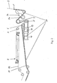
- FIG. 2 a guideway 17 of a machine and in this sense automatic Brueinzugssystems is located.
- the guideway 17 is formed by guide rails, which are arranged on one side next to the Bruleitffenn and serve the leadership of a driven pulling-in means.
- the guide track 17 leads around the deflection devices 11 and 12 of the cutting register adjustment device 10.
- the guide track 17 is also guided around the entry guide roller 5 and the exit guide roller 6 and further along the path of the first track B1.
- FIG. 3 shows the web B in this state immediately after machine retraction over the entire path of the later first track B1.
- the rollers 3a and 3b of the slitter are moved against each other and the web B is cut longitudinally between the later printed images.
- the web start of the second web strand B2 is manually from the outlet guide roller 6 via the inlet roller 7 for the turning bar device 8, by the turning bar device. 8 through and fed through the downstream Bruleitstoff.
- the manual retraction via a deflection of a cutting register adjustment device is saved, which brings Zeitvortelle and contributes to the reduction of Einziehêtn.
- FIG. 4 shows the web B after the longitudinal cutting and before the formation of a web start for the second web strand B2.
- FIG. 1 is also a control and regulating device shown, which serves the control and regulation of the adjustment movements of the two deflection devices 11 and 12.
- the control and regulating device comprises two sensors 23 and 24, a control and regulating member 20 and two motor actuators 21 and 22.
- the sensor 23 detects the position of the printed image on the passing below him first web strand B1, and the sensor 24 detects the position of the printed image on the traversing under him second track B2.
- the position signals of the sensors 23 and 24 are supplied to the control and regulating member 20.
- the control and regulating member 20 charged the two sensor signals by means of a suitable algorithm and forms from this by comparison with input command signals, the control signals for the actuators 21 and 22.
- the actuator 21 is coupled to the first deflection 11 and the actuator 22 to the second deflection 12.
- the actuators 21 and 22 act on the deflection devices 11 and 12 in accordance with the actuating signals formed by the control and regulating member 22, ie they effect the adjustment movement of the deflection devices 11 and 12 along their common axis of movement.
- the control and regulating member 20 with the sensors 23 and 24 and the actuators 21 and 22 forms a control for the setting of the correct cut register position for each of the web strands B1 and B2.
- these members form a control and regulation until the receipt of a basic setting.
- the Figures 3 and 4 The cut register setting device 10 and its immediate vicinity each show the same view in a three-dimensional representation, but in two different states of the cut register setting device 10.
- the states are differentiated by the positions which the deflection devices 11 and 12 occupy with respect to each other.
- the formation of the two deflection devices 11 and 12 each as a strand width, circular cylindrical, smooth roll body. Due to the design as only single-width roll body, the deflecting devices 11 and 12 can be arranged side by side in a small space.
- the arrangement and movable mounting of the deflectors 11 and 12 is such that they are in a first state, which in FIG.
- roller body forms when pulling the web start of a new web a simple guide roller.
- the inevitable clear gap between the free ends of the roll body is kept so narrow within the tolerances that it can be neglected for the entry of the web B. In this sense, the roll body is uniform.
- the deflecting axes formed by the deflecting devices 11 and 12 are aligned in the first state.
- the deflecting devices 11 and 12 each assume their starting base position relative to each other, in which a web with a free web beginning is pulled in.
- the baffles 11 and 12 can be moved apart in opposite directions by means of the actuators 21 and 22, for example in the in FIGS Figur4 shown second state in which their deflection axes are offset parallel to each other at a maximum distance.
- the deflection devices 11 and 12 assume positions in which the path path of the first web strand B1 has a minimum length and the path path of the second web strand B2 has a maximum path length.
- the diverters 11 and 12 can be moved from the position they take in the first state to its other two extreme positions, if required by the cut register control.
- Intermediate states are of course also adjustable, preferably continuously.
- the deflecting devices 11 and 12 are each guided linearly guided on their outer, mutually remote axial ends on one side of a frame along the axis of movement.
- the frame side, on which the first deflecting device 11 is mounted, is denoted by 14, and the frame side, on which the second deflecting device 12 is mounted, is designated by 16.
- the frame sides 14 and 16 each form a parallel to the axis of movement guideway.
- the deflection 11 and 12 are each rotatably mounted on one of two carriages 13 and 15, which is linearly stirred along the guide path formed by its frame side 14 or 16.
- the deflecting axes formed by the deflecting devices 11 and 12 each have a right angle to the guideways formed by the frame sides 14 and 16.
- the adjustability of the deflection 11 and 12 is designed by their storage and the coupling with the actuators 21 and 22 so that the necessary for the positioning of the cut register of the two web strands B 1 and B2 adjustment movements can be divided on the deflection 11 and 12, preferably at least substantially half each, more preferably exactly half of each. Accordingly, the maximum lengths of the adjustment of the deflectors 11 and 12 are the same. Due to the advantageous storage of the deflectors 11 and 12 immediately next to each other, the adjustment paths are even the same, i. the deflecting axis formed by the first deflecting device 11 and the deflecting axis formed by the second deflecting device 12 can be reciprocated between the two same outer extreme positions. The two deflection devices 11 and 12 are therefore equivalent in the ideal case described by way of example.
- the adjustability of the first deflector 11 opens up new possibilities for adjusting the cut register of the direct strand and the turning strand, i. for the control and / or regulation of the web strands B1 and B2.
- the cutting register In the adjustment of the cutting register is conventionally existing between direct strand and reversing strand difference in the positions of the respective print images alone by changes in length the path of the turning strand compensated.
- the printing unit ensures that the printed image on the direct line is positioned in the cut register.
- An adjustment of the length of the path of the direct line is made at best to a limited extent, this adjustment is not carried out in relation to the cut register of the other web strand or the cut registers of the several other web strands of the bundle, but solely with respect to the position of Section in the cross cutter.
- the path length of a strand is understood to be the length of the path of the relevant strand from its formation, that is to say the location of the longitudinal cutting up to the merging in the strands B1 and B2.
- the direct strand is the guide strand of the bundle to which the other web strands of the bundle are adjusted.
- This type of cut register setting requires, in the case of the other web strand or the several other web strands of the bundle, large adjustment paths for their adjustment devices serving for the adjustment.
- the adjustment paths are typically of the order of 200 to 400 mm. On the other hand, the speed of the adjustment is limited.
- a linear register as each of the deflecting means 11 and 12 represents a, the strand path according to experience to extend by a maximum of 1 mm per meter. If, for example, an adjustment travel, ie register travel, of 300 mm is required in order to switch from a print production to another print production with uninterrupted print production, at least 300 web meters pass through the printing press before the cut register is readjusted. If the print products are newspaper copies whose length is 1 m to simplify the estimation, then the new cut register is only set after 300 printed copies. The first 300 printed copies of the new production are waste paper.
- the adjustment movement required for the cutting register adjustment can now be divided between the two web strands B1 and B2. More generally, the adjustment path for the turning strand of the web strand bundle is reduced by a part thereof, preferably half of the adjustment path for the turning strand, from the Thomasregistereinstellglied for the direct strand, in the embodiment, the first deflection 11, is taken over.
- the total Verwellweg required is preferably divided evenly. If the direct strand is combined with several web strands into a bundle, the adjustment paths are preferably divided as evenly as possible on the web strands to be joined. The adjustment is advantageously carried out under the optimization strategy that the positioning time is minimal assuming the same adjustment speeds for the setting of the cutting register.
- the path of the first track B1 is extended to the same extent as the track of the second track B2 is shortened.
- the path length changes to be made can also be a setting in the opposite direction, ie a shortening of the path of the first track B1 and extending the path of the second Brustrangs B2 be advantageous.
- the reduction of the length of the adjustment path of the second deflection device 12 is particularly advantageous in the case of a change from one printed product to another in the case of continued printing production, since the waste can be considerably reduced.
- the new cut register setting may result in the first web strand B1 not being in register with the cut due to the change in length of its path even if the color register (s) were in register prior to adjustment with the cut.
- the direct, first web strand B1 is otherwise brought into the register with the cut, for example by means of a registration roller for the web B or preferably by a coordinated adjustment of the personallysreglster the color transferring to the web B cylinder.
- the cross-cutting device can be adjusted in accordance with the path length changes of the web strands B1 and B2.
- both the circumferential register of the color-transmitting cylinder and the cross-cutting device can be adjusted adjusted.
- This part of the registration is carried out jointly with all web strands B1 and B2 of the same web B or all web strands of the bundle. Pathway and strand-wise registration are matched for the cut per bundle and preferably executed simultaneously.
- the said on the basis of the embodiment with respect to the register by means of these further cut register adjusting members applies also to the general case of the invention, in which the considered web strand bundle on the web strands B1 and B2 also contains one or more further web strands or only one of the web strands B1 and B2.
- the invention is already advantageous for a printing machine for a single-sided, monochrome printing or a two-sided printing in a single printing nip of a printing unit, as for the purposes of explaining a reference to the FIG. 1 is described.
- the printing machine can have a plurality of printing units of this type, ie rubber-rubber printing units, and / or of other types, for example satellite printing units, wherein the different types of printing units are arranged and operated such that the web B is multicolored or a plurality of webs B is or will be printed in one or more colors.
- each of the web-contacting and color printing on the web cylinder is ever driven by a separate motor, wherein the required synchronization of the respective cylinder is not mechanically, but signal technology, such as electronic, made.
- This type of formation of the pressure points is advantageous in view of the adjustment of the color register, with which preferably the adjustment of the direct strand B 1 is compensated for cutting.
- a cut register adjustment device 10 is preferably arranged in each case and also preferably has the further features of this adjustment device.
- the web strands B1 and B2 are combined, for example, with a third web strand B3 to form a bundle and the position difference of the second web strand B2 for cutting, for example, 300 mm and the position difference of the third web strand B3 for cutting, for example, 400 mm, while the first web strand B1 at the moment
- the strand path length change required in the conventional adjustment method would be 300 mm for the second web strand B2 and 400 mm for the third web strand B3, while nothing would be compensated for in the first web strand B1 and the displacement of the first deflecting device 11 would therefore be "zero".
- the largest Strangwegin Sung and largest Verstellwegn the respective deflection would be required for the third track B3. Its deflection would have to be moved by the largest Verstellwegin from its original position.
- the total required response time would correspond to the time that would be required to move the deflection device for the third web strand B3 from its initial position taken before the adjustment by the adjustment path length required for a strand path length change of 400 mm.
- the path length of the first web strand B1 is lengthened by 200 mm in the most optimal embodiment variant of the adjustment method according to the invention, in which the largest of the adjustment path lengths is minimized. Accordingly, the path of the second web strand B2 does not have to be shortened by 300 mm, but only by 100 mm. In particular, however, the largest of the Strangwegzen Sungen to be performed, namely that for the third web strand B3, significantly reduced. The shortening of the path length required for the third track B3 is no longer 400 mm, but only 200 mm. In the example, this corresponds to the minimum of the path length change for the third track B3.
- the largest of the adjustment path lengths by which one of the deflection devices must be adjusted is 100 mm.
- the first deflecting device 11 must be adjusted by 100 mm for an extension and the deflection device for the third web strand B3 by also 100 mm for a magnitude equal in magnitude shortening of the relevant strand path.
- the largest of the strand path length changes and the largest of the path lengths were minimized.
- the invention is not limited to such absolute minimization but also includes suboptimal embodiments of the adjustment method.
- the path of the first track B1 is extended only by 150 mm, for example, and accordingly the path of the second track B2 is shortened by 150 mm and the path of the third track B3 is shortened by 250 mm to bring all three web strands B1, B2 and B3 to the same cut register position.
- the third web strand B3 may be a web strand which is obtained by longitudinal cutting from the same web B as the first web strand B1 and the second web strand B2.
- the third web strand B3 need not be from the same web B as the other two web strands B1 and B2, but may have been obtained from another web by slitting. In fact, it may even have been handled directly in web width from a roll.
- the adjustment method according to the invention the arrangement according to the invention of individual or all cut register setting members for the web strands in front of the turning bars and also the arrangement of the cut register setting members per web for their strands in mutual spatial proximity are present in many different web guides, which lead to the formation of web strand bundles, advantageous.
Abstract
Description
Die Erfindung betrifft eine Druckmaschine mit einem Schnittstelten-Register in der eine endlos geförderte Bahn bedruckt wird oder vorzugsweise eine Mehrzahl solcher Bahnen bedruckt werden. Ferner betrifft die Erfindung ein Verfahren für die Einstellung des Schnittregisters von bedruckten Bahnsträngen, die aus einer oder mehreren Bahnen durch Längsschneiden erhalten wurden. Die Druckmaschine ist vorzugsweise eine Rollendruckmaschine, in der die Bahn oder die mehreren Bahnen je von einer Rolle fortlaufend abgewickelt werden. Besonders bevorzugt kommt die Erfindung im Rollenrotationsdruckvon großen Zeitungsauflagen zum Einsatz.
Aus der
From the
In der laufenden Druckproduktion solcher Druckmaschinen wird die Bahn oder werden tiblicherweise eine Mehrzahl von Bahnen mit wenigstens zwei nebeneinander angeordneten Druckbildern fortlaufend bedruckt. In Förderrichtung gesehen kann die Bahn hintereinander je mit dem gleichen Druckbild oder einer periodischen Abfolge von zwei oder grundsätzlich auch noch mehr unterschiedlichen Druckbildern bedruckt werden. Zwischen den nebeneinander angeordneten Druckbildern wird die Bahn oder werden die mehreren Bahnen in Bahnstränge längsgeschnitten. Mehrere Bahnstränge werden entsprechend der laufenden Druckproduktion zu einem Bündel zusammengeführt und gemeinsam quer zu der Förderrichtung des jeweiligen Bündels geschnitten, um die einzelnen Druckprodukte, beispielsweise Zeitungen oder Magazine, zu erhalten. Im Zeitungsdruck werden im Allgemeinen für den Erhalt des Druckprodukts mehrere Bündel zusammengeführt und gemeinsam quer geschnitten. Die Bahnstränge, die jeweils ein Bündel bilden, werden so zusammengeführt, dass die Druckbilder der Bahnstränge eines Bündels zwischen zwei in Förderrichtung aufeinander folgenden Schnitten möglichst genau zentriert sind. Die Bahnstränge eines Bündels werden für den Erhalt ihres sogenannten Schnittregisters, d.h. für die Zentrierung zwischen den Schnitten, mittels geeigneter Operationen beeinflusst. Bezogen auf den einzelnen Bahnstrang handelt es sich bei diesen Operationen um gezielt auf das Schnittregister des betreffenden Bahnstrangs durchgeführte Veränderungen der Weglänge, die der Bahnstrang zwischen dem Ort des Bedruckens und dem Ort des Querschneidens zurücklegt. Durch eine gezielte Weglängenänderung wird somit die Schnittregisterposition des betreffenden Strangs, oder kurz gesagt, dessen Schnittregister, eingestellt.In the current printing production of such printing presses, the web or, more usually, a plurality of webs are continuously printed with at least two juxtaposed printed images. As seen in the conveying direction, the web can be successively printed each with the same print image or a periodic sequence of two or basically even more different print images. Between the juxtaposed printed images, the web or the multiple webs is cut longitudinally into web strands. Several web strands are combined into a bundle according to the current print production and cut together across the conveying direction of the respective bundle, in order to obtain the individual printed products, for example newspapers or magazines. In newspaper printing, several bundles are generally merged together to obtain the printed product and cut together across. The web strands, which each form a bundle, are brought together so that the printed images of the web strands of a bundle are centered as accurately as possible between two consecutive sections in the conveying direction. The web strands of a bundle are used to obtain their so-called cut register, i. for centering between cuts, influenced by appropriate operations. In relation to the individual web strand, these operations are changes to the path length made specifically for the cutting register of the relevant web strand, which the web strand travels between the location of the printing and the location of the transverse cutting. By a targeted Weglängenänderung thus the cut register position of the strand in question, or in short, the cut register set.
Für die Einstellung des Schnittregisters haben sich Schnittregisterwalzen bewährt. Die Schnittregisterwalzen werden je von einem Bahnstrang umschlungen, üblicherweise um 180°. Durch eine Verstellbewegung einer Schnittregisterwalze quer zu ihrer Längsachse wird der Weg des sie umschlingenden Bahnstrangs verlängert oder verkürzt und auf diese Weise das Schnittregister des betreffenden Bahnstrangs eingestellt.For the adjustment of the cutting register, cutting register rollers have proven themselves. The cut register rollers are each looped around by a web strand, usually by 180 °. By an adjusting movement of a cutting register roller transversely to its longitudinal axis, the path of the track looping around it is lengthened or shortened and in this way the cutting register of the relevant web strand is adjusted.
Üblicherweise werden aus der Bahn durch das Längsschneiden zwei oder drei Bahnstränge erhalten, die zusammengeführt und längsgefalzt werden. Um das Zusammenführen zu ermöglichen, werden die Bahnstränge je einzeln einer oder mehreren geeigneten Wendeoperationen unterzogen. Einer der Bahnstränge der Bahn oder, im Falle mehrerer bedruckter Bahnen, je ein Bahnstrang aus jeder Bahn, wird keiner Wendeoperation unterzogen und In diesem Sinne direkt zu dem Ort des Zusammenführens gefördert. Solch ein Bahnstrang wird im Folgenden als Direktstrang bezeichnet. Ein Bahnstrang, der einer oder mehreren Wendeoperationen unterzogen wird, erhält zur Unterscheidung im Folgenden die Bezeichnung Wendestrang.Usually two or three web strands are obtained from the web by the longitudinal cutting, which are brought together and longitudinally folded. In order to facilitate the merging, the web strands are individually subjected to one or more suitable turning operations. One of the web strands of the web or, in the case of multiple printed webs, one web strand from each web, undergoes no turning operation and in that sense conveys it directly to the point of merge. Such a web strand is hereinafter referred to as direct strand. A web strand which is subjected to one or more turning operations is given the name twisting strand for distinction below.
Druckmaschinen und Verfahren der Bahnführung der vorstehend beschriebenen Art betrifft die Erfindung insbesondere auch.Printing machines and methods of web guide of the type described above relates to the invention in particular also.
Soweit bei den bekannten Druckmaschinen und Verfahren der Bahnführung für den Direktstrang eines Bahnstrangbündels dessen Schnittregisterposition eingestellt wird, handelt es sich um Einstellungen in der laufenden Druckproduktion zur Korrektur einer Abweichung des Farbregisters zum Schnitt. Für jeden Wendestrang des Bündels wird die Schnittregisterposition durch eine Verstellung der Bahnlänge des betreffenden Wendestrangs zu Beginn einer neuen Druckproduktion neu eingestellt oder in der laufenden Druckproduktion in Anpassung an Änderungen der Position des Direktstrangs eingestellt. Die Einstellung der Schnittregisterposition des Direktstrangs wird hiervon nicht beeinflusst. Der Direktstrang bildet sozusagen den Leitstrang, auf den alle anderen Bahnstränge des Bündels eingestellt werden.As far as in the known printing machines and methods of web guide for the direct strand of a web strand bundle whose cut register position is set, it is settings in the current print production to correct a deviation of the color register to the section. For each twist strand of the bundle, the cut register position is readjusted by adjusting the web length of the respective turn strand at the beginning of a new print production, or is adjusted in current print production to accommodate changes in the direct strand position. The setting of the cutting register position of the direct line is not affected by this. The direct strand forms, so to speak, the leading strand to which all other web strands of the bundle are adjusted.
Ein Problem ist die Einstellung der Maschine auf eine neue Druckproduktion. Die Einstellung ist bei einem Anfahren der Maschine oder auch bei einem Wechsel der Druckproduktion bei laufender Maschine erforderlich. Es besteht die Tendenz, dass die Auflagengröße, die mit der gleichen Maschineneinstellung gedruckt werden, abnehmen, während im gleichen Maße die Zahl der Anfahrvorgänge und insbesondere die fliegenden Wechsel der Druckproduktion bei laufender Maschine zunehmen, d.h. es steigen die Anforderungen an die Flexibilität der Maschine. Aufgrund des zunehmenden Kostendrucks wird die Einsparung von Makulatur jedoch gleichzeitig immer wichtiger.One problem is the setting of the machine to a new print production. The setting is required when starting the machine or when changing the print production while the machine is running. There is a tendency for the run sizes printed at the same machine setting to decrease, while at the same time the number of startup operations, and in particular the flying changes in print production with the machine running, will increase. the demands on the flexibility of the machine increase. Due to the increasing cost pressure, however, the waste of waste is becoming more and more important.
Es ist eine Aufgabe der Erfindung, die durch die Umstellung auf eine neue Druckproduktion anfallende Makulatur, d.h. die Anzahl der nicht verwertbaren Druckprodukte, zu verringern.It is an object of the invention to reduce the waste resulting from the conversion to a new print production, i. reduce the number of non-recyclable printed products.
Die Erfindung hat erkannt, dass die Reduzierung der Einstellzeit, die für die Einstellung der Schnittregisterposition von Bahnsträngen benötigt wird, einen wesentlichen Beitrag zur Reduzierung der Makulatur leisten kann. Dies gilt für den fliegenden Wechsel von einer Druckproduktion auf eine neue Druckproduktion bei weiterlaufender Druckmaschine und gilt insbeson-dere auch für solche Fälle, in denen für die neue Druckproduktion ein neuer Bahnanfang in die Druckmaschine eingezogen wird.The invention has recognized that reducing the settling time required to set the cut register position of web cords can make a significant contribution to paper waste reduction. This applies to the flying change from a print production to a new print production when the printing press continues to run and, in particular, applies also for those cases where a new web start is fed into the press for the new print production.
Die Erfindung hat zum Gegenstand die Einstellung des Schnittregisters in einer neuen Druckproduktion, nämlich die Einstellung bis zu dem Zeitpunkt, ab dem sämtliche Schnittregisterpositionen der Bahnstränge eines Bahnstrangbündels des neuen Druckprodukts eingestellt sind. Ebenso gehört zum Gegenstand der Erfindung die Einstellung des Schnittregisters in einer laufenden Druckproduktion, um nach Abschluss einer Grundeinstellung in der laufenden Druckproduktion zu verhindern, dass nicht tolerierbare Abweichungen in der Schnlttreglsterposmon von einem oder mehreren der Bahnstränge des Bündels auftreten.The subject of the invention is the setting of the cut register in a new print production, namely the setting up to the time from which all cut register positions of the web strands of a web strand bundle of the new printed product are set. Likewise, the subject of the invention is the setting of the cut register in a current print production to prevent after completion of a basic setting in the current print production that intolerable deviations occur in the Schnlttreglsterposmon of one or more of the web strands of the bundle.
In einem Verfahren, wie die Erfindung eines betrifft, wird eine Bahn mit Druckbildern fortlaufend bedruckt. Die bedruckte oder erst noch zu bedruckende Bahn wird in einen ersten Bahnstrang und wenigstens einen zweiten Bahnstrang längsgeschnitten. Falls die Bahn quer zu ihrer Förderrichtung mit zwei oder drei nebeneinander angeordneten Druckbildern bedruckt ist, wie dies im Rollenrotationsdruck von Zeitungsauflagen üblich ist, wird die Bahn zwischen den bereits gedruckten oder erst noch zu druckenden Druckbildern in entsprechend zwei oder drei Bahnstränge längsgeschnitten. Die Erfindung ist auf diesen bevorzugten Anwendungsfall jedoch nicht beschränkt, betrifft also beispielsweise auch einen Längsschnitt in mehr als drei Bahnstränge.In one method, as the invention relates to one, a web is printed continuously with printed images. The printed or yet to be printed web is cut longitudinally into a first web strand and at least one second web strand. If the web is printed transversely to its conveying direction with two or three printed images arranged next to one another, as is usual in web-fed rotary printing, the web is cut longitudinally between the already printed or still to be printed images in accordance with two or three web strands. However, the invention is not limited to this preferred application, ie, for example, also relates to a longitudinal section in more than three web strands.
Im weiteren Verlauf des Verfahrens wird ein oder werden mehrere Bahnstrangbündel gebildet. Insbesondere können die aus der Bahn erhaltenen Bahnstränge allein oder zusammen mit einem Bahnstrang oder mehreren Bahnsträngen einer weiteren Bahn oder mehrerer weiterer Bahnen das einzige oder eines der mehreren Bahnstrangbündel bilden. Es kann auch ein Teil der aus der Bahn erhaltenen Bahnstränge ein Bahnstrangbündel allein oder zusammen mit einem oder mehreren Bahnsträngen von einer oder mehreren welteren Bahnen bilden, wobei das gleiche auch für den verbleibenden anderen Teil der aus der Bahn efialtenen Bahnstränge gilt. Entsprechend der Bildung des Bahnstrangbündels oder der mehreren Bahnstrangbündel werden die aus der Bahn erhaltenen Bahnstränge miteinander und/oder mit anderen Bahnsträngen zu dem Bahnstrangbündel oder den mehreren tiahnstrangbündeln zusammengeführt.In the further course of the method, one or more web-strand bundles are formed. In particular, the web strands obtained from the web alone or together with one web strand or several web strands of another web or several further webs can form the single or one of the plurality of web strand bundles. Also, a part of the web strands obtained from the web may form a web strand bundle alone or together with one or more web strands of one or more world webs, the same also being valid for the remaining other part of the web strands being fed from the web. In accordance with the formation of the web strand bundle or the plurality of web strand bundles, the web strands obtained from the web are combined with one another and / or with other web strands to form the web strand bundle or the plurality of strand bundles.
Das so erhaltene, wenigstens eine Bahnstrangbündel wird quergeschnitten, d.h. es wird quer zur Förderrichtung des Bahnstrangbündels zwischen zwei aufeinanderfolgenden Druckbildern geschnitten. Das Querschneiden kann für mehrere Bahnstrangbündel gemeinsam durchgeführt werden, wie dies beispielsweise im Druck von Zeitungsauflagen üblich ist. Allerdings betrifft die Erfindung auch den Fall, dass nur ein einziges Bahnstrangbündel gebildet und quergeschnitten wird.The thus obtained, at least one web strand bundle is cross-cut, i. it is cut transversely to the conveying direction of the web strand bundle between two successive printed images. Cross cutting can be carried out jointly for several web bundles, as is common, for example, in the printing of newspaper editions. However, the invention also relates to the case that only a single web strand bundle is formed and cross-cut.
Um die Schnittregisterpositionen der Bahnstränge des wenigstens einen Bahnstrangbündels einzustellen, werden die Längen der Wege der Bahnstränge in einer aufeinander abgestimmten Art und Weise um Weglängenänderungen verstellt. Die Weglängen der Bahnstränge werden je von dem Ort der Entstehung des betreffenden Bahnstrangs, im Allgemeinen der Ort des Längsschneidens, bis zu dem Ort des Zusammenführens der Bahnstränge des Bündels gemessen. Zum Zwecke der Verstellung der Weglängen ist für jeden der Bahnstränge des Bündels je wenigstens eine Umlenkeinrichtung im Strangweg zwischen dem Ort der Entstehung und dem Zusammenführen angeordnet. Die Umlenkeinrichtungen bilden je eine Umlenkachse, um die der zugeordnete Bahnstrang umgelenkt wird. Die Umlenkachsen sind um Verstellweglängen verstellbar. Die Umlenkeinrichtungen können insbesondere Schnittregisterwalzen oder grundsätzlich auch andere Arten geeigneter Elnstellelnrichtungen sein.In order to set the cut register positions of the web strands of the at least one web strand bundle, the lengths of the paths of the web strands are adjusted by path length changes in a coordinated manner. The path lengths of the web strands are in each case measured from the location of the formation of the relevant web strand, generally the location of the longitudinal cutting, to the location of the merging of the web strands of the bundle. For the purpose of adjusting the path lengths, at least one deflecting device is arranged in the strand path between the place of formation and the merging for each of the web strands of the bundle. The deflection devices each form a deflection axis about which the assigned web strand is deflected. The deflection axes are adjustable by Verstellweglängen. The deflection devices may in particular be cut register rollers or in principle also other types of suitable adjustment directions.
Nach der Erfindung werden die Weglängen der Bahnstränge so verstellt bzw. verändert, d.h. die pro Bahnstrang erforderliche Verstellweglänge der zugeordneten Umlenkeinrichtung bzw. Umlenkachse so gewählt, dass eine größte der Strangweglängenänderungen minimiert wird. Es wird somit nicht einer der Bahnstränge des Bündels als Leitstrang bestimmt, auf dessen Schnittregisterposition die Schnittregisterpositionen der anderen Bahnstränge eingestellt werden, sondern es wird für jeden Bahnstrang des Bündels solch eine Verstellweglänge für die zugeordnete Umlenkeinrichtung gewählt, dass eine größte der Verstellweglängen kleiner ist als sie es wäre, wenn einer der Bahnstränge des Bündels als fester Leitstrang für die anderen Bahnstränge des Bündels bestimmt würde. Nach der Erfindung wird somit kein Leitstrang fest vorbestimmt, sondern es werden die Verstellweglängen und die sich aus den Verstellweglängen ergebenden Längenänderungen der Strangwege auf eine Minimierung der maximalen Verstellweglänge bemessen.According to the invention, the path lengths of the web strands are so adjusted or changed, i. the required per track strand Verstellweglänge the associated deflection or deflection axis chosen so that a largest of Strangweglängenänderungen is minimized. It is thus not one of the web strands of the bundle determined as a Leitstrang on the cut register position, the cut register positions of the other web strands are set, but it is chosen for each web strand of the bundle such Verstellweglänge for the associated deflector that a largest of the Verstellweglängen is smaller than they it would be if one of the web strands of the bundle were designated as a fixed leader for the other web strands of the bundle. According to the invention, therefore, no Leitstrang firmly predetermined, but it is the Verstellweglängen and resulting from the Verstellweglängen length changes of the strand paths are dimensioned to minimize the maximum Verstellweglänge.
Es wird davon ausgegangen, dass die Verstellweglängen der Umlenkeinrichtungen bzw. Umlenkachsen und die Weglängenänderungen der Bahnstränge so korreliert sind, dass eine größte Verstellweglänge, um die eine der Umlenkeinrichtungen verstellt werden muss, um die Schnittregisterpostrion des zugeordneten Bahnstrangs einzustellen, auch die größte Weglängenänderung bewirkt. In Bezug auf das erfindungsgemäße Verfahren wird deshalb im folgenden der Begriff "Weglängenänderung" und in Bezug auf die erfindungsgemä-ße Vorrichtung der Begriff "Verstellweglänge" gebraucht. Soweit die vorstehend definierte Korrelation unterstellt wird, steht der eine der beiden Begriffe synonym für den anderen. Es kann eine einzige der Umlenkeinrichtungen für die Bahnstränge des Bündels die größte der Verstellweglängen aufweisen. Es kann jedoch auch der Fall eintreten, dass mehrere der Umlenkeinrichtungen um die größte der Verstellweglängen verstellt werden, wobei unter diesem Begriff ungeachtet der Richtung der Verstellbewegung die dem Betrage nach größte Verstellweglänge gemeint ist.It is assumed that the Verstellweglängen the baffles or deflecting axes and the path length changes of the web strands are correlated so that a largest Verstellweglänge by which one of the deflection must be adjusted to adjust the Schnittregisterpostrion the associated track, also causes the largest Weglängenänderung. With regard to the method according to the invention, the term "path length change" is therefore used below, and the term "adjustment path length" with reference to the device according to the invention. As far as the above-defined correlation is assumed, one of the two terms is synonymous with the other. It may have a single of the deflection of the web strands of the bundle, the largest of Verstellweglängen. However, it may also be the case that several of the deflection by the largest of Verstellweglängen be adjusted, which is meant by the term regardless of the direction of the adjustment, the magnitude of the adjustment path length.
Erfindungsgemäß die Verstellweglängen so gewählt, dass eine größte der Verstellweglängen minimiert wird. Durch einen geeigneten Algorithmus ermittelt eine Steuerungs- und/oder Regelungseinrichtung für jeden der Bahnstränge des Bündels individuell eine Verstellweglänge mit der Vorgabe, dass eine sich aus der Ermittlung ergebende größte Verstellweglänge minimiert wird. Vorteilhaft, obgleich weniger bevorzugt als die genannte optimale Variante, ist es auch, wenn die Verstellweglängen nicht auf die Minimierung der größten Verstellweglänge, sondern "nur" in Richtung auf solch eine Minimierung gewählt werden. Bilden beispielsweise lediglich zwei Bahnstränge das Bündel, so werden in der optimalen Ausführungsvariante, in der die größte der Verstellweglängen minimiert wird, die Verstellweglängen für beide Bahnsträngen dem Betrage nach gleich groß und dem Vorzeichen nach entgegengesetzt gewählt. Es wird im Falle der Minimierung der eine der Bahnstränge um die ermittelte Weglängenänderung verkürzt und der andere um die gleiche Weglängenänderung verlängert. In der suboptimalen Ausführungsvariante wird die Weglänge des einen der Bahnstränge, beispielsweise des ersten Bahnstrangs, in einem geringeren Ausmaß verändert als in der optimalen Ausführungsvariante, allerdings so, dass die für den Erhalt der korrekten Schnittregisterposition beider Bahnstränge erforderliche Weglängenänderung des anderen der Bahnstränge, im angenommenen Beispielfall des Wendestrangs, kürzer ist als sie es wäre, wenn die Weglängenänderung für den ersten Bahnstrang nicht vorgenommen würde. Bei mehr als zwei Bahnsträngen im Bündel kann es vorkommen, dass die Weglänge von einem oder mehreren dieser Bahnstränge weder verlängert noch verkürzt wird oder werden. Allerdings kann sich diese Situation nur für bestimmte Ausgangszustände der Bahnstränge ergeben, aber nicht in der Weise, dass für den jeweiligen Ausgangszustand im vorhinein ein Leitstrang feststeht. Jeder der Bahnstränge des Bündels kann in Abhängigkeit von dem vor der Verstellung bestehenden Ausgangszustand ein Bahnstrang sein, dessen Weglänge für die aus dem Ausgangszustand vorzunehmende Einstellung der Bahnstränge des Bündels nicht verändert wird.According to the invention the Verstellweglängen chosen so that a largest of the Verstellweglängen is minimized. By means of a suitable algorithm, a control and / or regulating device individually determines an adjustment path length for each of the web strands of the bundle with the stipulation that a largest adjustment path length resulting from the determination is minimized. It is also advantageous, although less preferred than the said optimal variant, if the displacement lengths are chosen not to minimize the greatest displacement length, but "only" in the direction of such minimization. If, for example, only two web strands form the bundle, then in the optimum embodiment variant in which the greatest of the displacing path lengths is minimized, the adjustment path lengths for both web strands are chosen to be equal in magnitude and opposite in sign. In the case of minimizing one of the web strands, it is shortened by the determined path length change and the other lengthened by the same path length change. In the suboptimal embodiment variant, the path length of one of the web strands, for example of the first web strand is changed to a lesser extent than in the optimal embodiment, but such that the required for obtaining the correct cut register position of both web strands path length change of the other of the web strands, in the assumed Example case of the turning strand, is shorter than it would be if the path length change for the first web strand would not be made. With more than two web strands in the bundle, it may happen that the path length of one or more of these web strands is neither lengthened nor shortened. However, this situation can only arise for certain initial states of the web strands, but not in such a way that for the respective initial state in advance a guidance strand is established. Each of the web strands of the bundle may be a web strand, the path length of which is not changed for the setting of the web strands of the bundle to be made from the initial state, depending on the initial state existing before the adjustment.
Die Druckmaschine umfasst nach der Erfindung für jeden Bahnstrang des Bündels eine Umlenkeinrichtung, die wenigstens eine querverstellbare Umlenkachse für den betreffenden Bahnstrang bildet. Die wenigstens eine verstellbare Umlenkachse pro Bahnstrang ist quer zu sich selbst um eine maximale Verstellweglänge verstellbar. Die maximale Verstellweglänge ist für jede der quer verstellbaren Umlenkachsen so groß, dass die Verstellwege zwischen den quer verstellbaren Umlenkachsen aufgeteilt werden können. Vorzugsweise ist die maximale Verstellweglänge jeder der querverstellbaren Umlenkachsen so groß, dass im Falle des Zusammenführens aller aus einer einzigen Bahn gebildeten Bahnstränge die Verstellwege zwischen diesen Umlenkachsen aufgeteilt werden können. Besonders bevorzugt sind die maximalen Verstellweglängen der quer verstellbaren Umlenkachsen gleich groß, so dass die Verstellweglängen zwischen den Bahnsträngen gleichmäßig aufgeteilt werden können. Ein Ziel der Erfindung wird jedoch auch bereits dann erreicht, wenn die maximalen Verstellweglängen zwar unterschiedlich groß sind, aber dennoch eine Aufteilung der Verstellwege zwischen den Umlenkachsen in einem für die Verkürzung der Einstellzeit relevanten Umfang vorgenommen werden kann. Als erfindungsgemäß wird eine Bewegbarkeit der quer verstellbaren Lenkachsen zumindest dann noch angesehen, wenn die maximalen Verstellweglängen sich um nicht mehr als 50 % unterschelden, d.h. wenn eine kleinste der maximalen Verstellweglängen wenigstens halb so groß wie eine größte der maximalen Verstellweglängen ist.
Was den ungewendeten Direktstrang oder die mehreren Direktstränge einer Druckproduktion anbetrifft, so hat die Erfindung zur Folge, dass auch die Einstellung der Schnittregisterposition des Direktstrangs auf Verkleinerung oder vorzugsweise auf Minimierung der größten Verstellweglänge, die für einen oder mehrere der Bahnstränge des Bündels des betreffenden Direktstrangs vorzunehmen ist, durchgeführt wird.The printing machine according to the invention comprises for each web strand of the bundle a deflection device which forms at least one transversely adjustable deflection axis for the relevant web strand. The at least one adjustable deflecting axis per track is adjustable transversely to itself by a maximum Verstellweglänge. The maximum displacement length is so great for each of the transversely adjustable deflection axes that the displacement paths between the transversely adjustable deflection axes can be divided. Preferably, the maximum Verstellweglänge each of the transversely adjustable deflection axes is so large that in the case of merging all formed from a single web web strands, the adjustment paths between these deflection axes can be divided. Particularly preferably, the maximum Verstellweglängen the transversely adjustable deflection axes are the same size, so that the Verstellweglängen between the web strands can be divided evenly. However, an object of the invention is already achieved when the maximum Verstellweglängen while different in size, but still a division of the adjustment paths between the deflection axes can be made in a relevant for the shortening of the setting time extent. As according to the invention, a mobility of the transversely adjustable steering axles is at least considered even if the maximum Verstellweglängen not underschelden by more than 50%, ie if a smallest of the maximum Verstellweglängen is at least half as large as a maximum of the maximum Verstellweglängen.
As for the unthreaded direct strand or the plurality of direct strands of a printed production, the invention results in the adjustment of the cut register position of the direct strand to reduction or preferably minimizing the largest Verstellweglänge that make for one or more of the web strands of the bundle of direct strand concerned is, is performed.
Da bei gleichschnellen Schnittregister-Einsteligliedem, wie die Umlenkeinrichtungen je eines bilden, dasjenige Einstellglied, das den größten Verstellweg zurückzulegen hat, die Einstellzeitbestimmt, die für die Einstellung der Schnittregisterpositionen der Bahnstränge des Bündels erforderlich ist, wird durch die Erfindung die Einstellzeit im Vergleich zu herkömmlichen Einstellverfahren mit vorbestimmtem Leitstrang verringert. In dem Maße, in dem die für die Einstellung der Schnittregisterpositionen erforderliche Einstellzeit verringert wird, kann auch die Makulatur verringert werden, vorausgesetzt dass innerhalb der Einstellzeit auch weitere Einstellungen der Maschinen parallel ausgeführt werden können, beispielsweise die Einstellung der Umtangsregister von farbübertragenen Druckzylindern.Since, in the same rapid cut register setting element, as the diverters form one each, the one adjusting member to travel the largest displacement determines the settling time required for adjusting the cut register positions of the web strands of the bundle, the invention sets the settling time as compared with conventional ones Setting method with predetermined guide strand reduced. As the set time required to set the cut register positions is reduced, waste can also be reduced, provided that other settings of the machines can be made in parallel within the set time, such as setting the register of color transfer printing cylinders.
Die vorstehend als optimal bezeichnete Ausführung der Wegminimierung ist in Strenge nurdann tatsächlich optimal, wenn die Stellgeschvilndigkehen der Schnittregister-Einstellglieder gleich sind. Dies muss jedoch nicht der Fall sein. Vorzugsweise können die Stellgeschwindigkeiten der Schnittregister-Einstellglieder variiert werden, um in Abhängigkeit von bestimmten Betriebsparametern mit angepasster Geschwindigkeit verstellen zu können, beispielsweise in Abhängigkeit von der Bahngeschwindigkeit, einer Materialeigenschaft des Bahnmaterials wie beispielsweise E-Modul und/oder Bahndicke und/oder im Falle des Nassdrucks in Abhängigkeit von den Strangfeuchten.The execution of the path minimization described above as optimal is strictly optimal only if the setting properties of the cut register setting members are the same. However, this does not have to be the case. Preferably, the actuating speeds of the cut register adjusting members can be varied to adjust at a suitable speed depending on certain operating parameters, for example, depending on the web speed, a material property of the web material such as modulus and / or web thickness and / or Wet pressure depending on the strand moisture.
In diesem Zusammenhang ist ferner darauf hinzuweisen, dass es sogar als besonders vorteilhaft angesehen wird, wenn die Strangweglängen nicht mit je der gleichen Stellgeschwindigkeit der Schnittregister-Einstellglieder verändert werden. So entspricht es einer bevorzugten Ausführung, wenn der Strangweg desjenigen Bahnstrangsbündels, dessen Weglänge um den größten Betrag verändert wird, auch mit der größten Stellgeschwindigkeit verändert wird. Falls die dem Betrage nach größte Weglängenänderung bei einem Bahnstrang des Bündels eine Verkürzung und bei einem anderen Bahnstrang des Bündels eine Verlängerung ist, so wird vorzugsweise die Verkürzung mit der größten Stellgeschwindigkeit vorgenommen. Es ist in solch einer Ausführung des Verfahrens daher besonders vorteilhaft, wenn als die nach der Verkleinerung oder gar Minimierung größte Weglängenänderung eine Verkürzung ist, da in diesem Fall die Einstellzeit minimiert werden kann. Wenn im Vorstehenden daher die Weglängenänderungen nur dem Betrage nach, nichtjedoch auch unter Berücksichtigung des Vorzeichens der jeweiligen Weglängenänderung betrachtet wurden, so gilt dies in Strenge nur unter der Voraussetzung, dass die Weglängenänderungen mit gleichen Stellgeschwindigkeiten der entsprechenden Schnittregister-Einstellgliedern durchgeführt werden.It should also be noted in this connection that it is even considered particularly advantageous if the strand path lengths do not coincide with each of the same actuating speed of the cut register setting members are changed. Thus, it corresponds to a preferred embodiment, when the strand path of that track bundle, the path length is changed by the largest amount, is also changed with the highest positioning speed. If the path length change which is the largest in terms of magnitude is a shortening for one web strand of the bundle and an extension for another web strand of the bundle, the shortening is preferably carried out with the greatest positioning speed. In such an embodiment of the method, it is therefore particularly advantageous if the maximum path length change after the reduction or even minimization is a shortening, since in this case the setting time can be minimized. Therefore, if in the foregoing, the path length changes were considered only in terms of magnitude, but not in consideration of the sign of the respective path length change, this is strictly applicable only on the premise that the path length changes are made at the same positioning speeds of the corresponding section register setting members.
Was die Vorrichtung anbetrifft, so haben die vorstehenden Überlegungen zur Folge, dass die Schnittregister-Einstellglieder in Form der genannten Umlenkeinrichtungen vorzugsweise mit variierbaren Stellgeschwindigkeiten angetrieben werden. Die Schnittregister-Einstellvorrichtung umfasst dementsprechend eine Steuerungseinrichtung, die zu einer Regelungseinrichtung weiterentwickelt sein kann, die solch eine Variation der Stellgeschwindigkeit erlaubt und vorzugsweise die optimale Stellgeschwindigkeit je individuell für die Stränge aufgrund der eingespeicherten und ausgewählten oder eingestellten Produktionskonfiguration errechnet und die Einstellglieder entsprechend steuert oder regelt.As far as the device is concerned, the above considerations result in that the cut-register adjusting members in the form of said deflecting means are preferably driven at variable actuating speeds. The cutting register adjusting device accordingly comprises a control device which may be further developed into a control device which allows such a variation of the positioning speed and preferably calculates the optimum positioning speed individually for the trains based on the stored and selected or adjusted production configuration and controls or regulates the adjusting members accordingly ,
Die Umlenkeinrichtung für einen Wendestrang des Bündels, d.h. für einen Bahnstrang, der vor der Bildung des Bündels gewendet wird, ist vorzugsweise vor dem Wendestangenbereich für diesen Wendestrang geordnet. Falls einer der mehreren Bahnstränge, die aus einer Bahn erhalten werden, ungewendet in das Bündel gefördert wird, ist die Umlenkeinrichtung für solch einen Direktstrang vorzugsweise in räumlicher Nähe zu der Umlenkeinrichtung des Wendestrangs angeordnet.The reversing strand diverter of the bundle, i. for a web strand which is turned prior to the formation of the bundle is preferably arranged in front of the turning bar region for this turning strand. If one of the plurality of web strands obtained from a web is conveyed unfavorably into the bundle, the deflecting device for such a direct strand is preferably arranged in spatial proximity to the reversing device of the reversing strand.
Die Umlenkeinrichtungen für die Bahnsträngen der Bahn sind in bevorzugter Ausführung der Erfindung so angeordnet, dass eine noch nicht längsgeschnittene Bahn um die Umlenkeinrichtungen gleichzeitig eingezogen werden kann, wodurch der maschinelle Bahneinzug erheblich erleichtert wird. Um dies zu erreichen, sind zwischen den Umlenkeinrichtungen keine sonstigen Umlenkeinrichtungen angeordnet, die nur von einem einzigen der Bahnstränge der Bahn umschlungen werden. Vorzugsweise sind sie sogar in dem Sinne nebeneinander angeordnet, dass auf dem Weg der Bahn zwischen ihnen keinerlei sonstige Umlenkeinrichtungen für die Bahn angeordnet sind. Vorzugsweise wird bei dem Bahneinzug erst dann längsgeschnitten, wenn die Bahn durch die derart gebildete Schnittregister-Einstellvorrichtung eingezogen worden ist.The diverters for the web strands of the web are arranged in a preferred embodiment of the invention so that a not yet longitudinally cut web can be pulled around the deflectors simultaneously, whereby the machine web feed is considerably facilitated. To achieve this, no other deflection devices are arranged between the deflection, which are wrapped only by a single of the web strands of the web. Preferably, they are even arranged side by side in the sense that no other deflection devices for the web are arranged on the path of the web between them. Preferably, the web feeder is cut longitudinally only when the web has been pulled in by the cut register adjusting device thus formed.
Die Anordnung der Umlenkeinrichtung für den einzigen oder die mehreren Wendestränge der Bahn vor der Wendestangeneinrichtung hat über die Vereinfachung eines maschinellen Bahneinzugs hinaus den weiteren Vorteil, dass die zugeordnete Umlenkeinrichtung die Breite eines einfachen Strangs haben kann und nicht mehr, wie bislang, wenigstens doppelte Strangbreite haben muss.The arrangement of the reversing device for the single or multiple turning strands of the web in front of the turning bar device has the further advantage over the simplification of a machine web take-in that the associated deflecting the width of a simple strand and not more, as before, have at least twice the strand width got to.
In der Ausführungsform, in der zwei Umlenkeinrichtungen quer zu den Bahnsträngen in räumlicher Nähe nebeneinander angeordnet sind, sind sie vorzugsweise je nur an einer Seite des Gestells abgestützt, während sie je mit einem freien Ende in Richtung auf die jeweils andere Gestellseite zu ragen. Durch eine zwischen den beiden Umlenkeinrichtungen stattfindende relative Verstellbewegung können diebeiden Umlenkeinrichtungen vorzugsweise in eine Position gebracht werden, in der sie miteinander fluchten und eine vorzugsweise zylindrische, glatte, einheitliche Oberfläche für die einzuziehende Bahn bilden. Werden drei Bahnstränge aus einer Bahn gebildet, so ist die Umlenkeinrichtung für den dritten Strang vorzugsweise ebenfalls vor den Wendestangen angeordnet, insbesondere kann die dritte Umlenkeinrichtung neben den beiden anderen angeordnet sein.In the embodiment in which two baffles are arranged transversely to the web strands in close proximity to each other, they are preferably supported on only one side of the frame, while each projecting with a free end towards the other frame side. By means of a relative adjustment movement taking place between the two deflection devices, the two deflection devices can preferably be brought into a position in which they are aligned with one another and form a preferably cylindrical, smooth, uniform surface for the web to be pulled in. If three web cords are formed from one web, the deflecting device for the third web is preferably likewise arranged in front of the turning bars, in particular the third deflecting device can be arranged next to the other two.
Bevorzugte weitere Merkmale der Erfindung werden in den Unteransprüchen und durch die beanspruchten Kombinationen von Merkmalen mehrerer Unteransprüche mit den unabhängigen Ansprüchen offenbart.
Ein Ausführungsbeispiel der Erfindung wird nachfolgend anhand von Figuren erläutert. An dem Ausführungsbeispiel offenbar werdende Merkmale bilden je einzeln und in jeder Merkmalskombination die Gegenstände der Ansprüche weiter. Es zeigen:
- Figur 1
- eine Druckmaschine mit einer Schnittregister-Einstellvorrichtung, die vor einer Wendestangeneinrichtung angeordnet ist,
Figur 2- eine Ansicht der in einem ersten Zustand befindlichen Schnittregister-Einstellvorrichtung,
- Figur 3
- eine perspektivische Darstellung der in einem ersten Zustand befindlichen Schnittregister-Einstellvorrichtung und
Figur 4- eine perspektivische Darstellung der in einem zweiten Zustand befindlichen Schnittregister-Einstellvorrichtung.
An embodiment of the invention will be explained below with reference to figures. The features disclosed in the exemplary embodiment form the subject of the claims individually and in each combination of features. Show it:
- FIG. 1
- a printing machine with a cutting register adjustment device, which is arranged in front of a turning bar device,
- FIG. 2
- 4 is a view of the cutting register adjusting device in a first state;
- FIG. 3
- a perspective view of the present in a first state cutting register adjustment device and
- FIG. 4
- a perspective view of the present in a second state cutting register adjustment device.
Für die Bildung der einzelnen Druckexemplare, im Ausführungsbeispiel Zeitungsexemplare, wird die Bahn B nach dem Bedrucken mittels einer Längsschneideinrichtung zwischen den Druckbildern längsgeschnitten. Die Längsschneideinrichtung wird von einer Schneidrolle 3a und einer Gegenrolle 3b gebildet, die je zu einer Seite der Bahn B einander gegenüberliegend angeordnet sind. Durch das Längsschneiden werden aus der Bahn B zwei Bahnstränge B 1 und B2 erhalten, die im Folgenden als erster Bahnstrang B 1 und zweiter Bahnstrang B2 bezeichnet werden. Die Bahnstränge B 1 und B2 werden anschließend gemeinsam über eine Zugwalze 4 zu einer Schnittregister-Einstellvorrichtung 10 gefördert. Bei dem Auslaufen aus der Schnittregister-Einstellvorrichtung 10 trennen sich die Wege der Bahnstränge B1 und B2.For the formation of the individual printed copies, newspaper copies in the exemplary embodiment, the web B is cut longitudinally after printing by means of a longitudinal cutting device between the printed images. The longitudinal cutting device is formed by a cutting
Der erste Bahnstrang B1 wird von der Schnittregister-Einstellvorrichtung 10 aus lediglich über Bahnleitmittel ohne Wende- oder Kehroperationen zu einer Längsfalzeinrichtung 9, die vorzugsweise als Falztrichter ausgebildet ist, geführt. Der zweite Bahnstrang B2 läuft aus der Schnittregister-Einstellvorrichtung 10 aus und in eine Wendestangeneinrichtung 8 ein. Bei dem Durchlaufen der Wendestangeneinrichtung 8 wird der zweite Bahnstrang B2 gewendet und/oder gekehrt und anschließend über einer Einlaufwalze der Längsfalzeinrichtung 9 mit dem ersten Bahnstrang B1 zu einem Bahnstrangbündel zusammengeführt, das im Ausführungsbeispiel lediglich aus den beiden Bahnsträngen B1 und B2 besteht. Ebenso ist es jedoch möglich, dass ein oder mehrere weitere Bahnstränge einer anderen Bahn oder von mehreren anderen Bahnen mit den beiden Bahnsträngen B1 und B2 vor der Längsfalzeinrichtung 9 vereinigt werden. Die in dem Bündel übereinanderliegenden Bahnstränge B1 und B2 werden bei dem Durchlaufen der Längsfalzeinrichtung 9 gemeinsam längsgefalzt und in eine Querschneideinrichtung 25 gefördert. Die Querschneideinrichtung 25 kann insbesondere ein Schneidzylinder eines Falzapparats sein, wie sie üblicherweise im Zeitungs-Rollenrotationsdruck verwendet werden. Die längsgefalzten und quergeschnittenen Einzelexemplare von Druckprodukten sind mit P bezeichnet. Falls es sich, wie im Ausführungsbeispiel, um Zeitungsexemplare handelt, werden sie nach dem Querschneiden noch quergefalzt, um schließlich die Zeitungsexemplare zu erhalten. Obgleich bereits ein lediglich aus den Bahnsträngen B1 und B2 bestehendes Bahnstrangbündel nach dem Querschneiden ein Druckprodukt P bilden kann, so werden beispielsweise im Zeitungsdruck üblicherweise weitere, gleichermaßen gebildete Bahnstrangbündel mit dem Bahnstrangbündel B1/B2 vereinigt und anschließend die mehreren Bahnstrangbündel aufeinanderliegend in der Querschneideeinrichtung 25 quergeschnitten.The first web strand B1 is guided from the cut
Mittels der Schnittregister-Einstellvorrichtung 10 wird dafür gesorgt, dass die Druckbilder der Bahnstränge B1 und B2 stets zwischen zwei aufeinanderfolgenden Schnitten der Querschneideinrichtung 25 zu liegen kommen und zwischen den Schnitten der Praxis angemessen zentriert sind, d.h. in Bezug auf das gemeinsame Schnittregister ausreichend genau positioniert sind. Für diese Positionierung müssen die unterschiedlichen Wege der Bahnstränge B1 und B2 von dem Druck bis zu dem Ort der Zusammenführung in der Längsfalzeinrichtung 9 und gegebenenfalls ein Versatz der nebeneinander angeordneten Druckformen der Druckformzylinder in Umfangsrichtung, d.h. ein Versatz der Druckbilder des ersten Bahnstrangs B1 zu den Druckbildern des zweiten Bahnstrangs B2 in Förderrichtung F, ausgeglichen werden. Im Zeitungsdruck ist solch ein Versatz üblich, um Unwuchten durch Kanalschläge der farbübertragenen Zylinder der Druckwerke zu reduzieren. Zu berücksichtigen ist ferner die in Förderrichtung F gemessene Länge der Druckbilder, die in einer Druckmaschinensteuerung letztlich durch den Umfang der Druckformzylinderrepräsentiertwird. Falls aufgrund der unterschiedlichen Wege der Bahnstränge B1 und B2 in einen praktisch relevanten Ausmaß für die Schnittregister-Position relevante Längenunterschiede aufgrund unterschiedlicher Längsdehnungen auftreten, werden auch diese das Schnittregister beeinflussende Längendifferenzen mit Hilfe der Schnittregister-Einstellvorrichtung 10 ausgeglichen. Die unterschiedlichen Einflussfaktoren führen dazu, dass die Position der Druckbilder der Bahnstränge B1 und B2 von der korrekten Schnittregisterposition abweicht. Diese Abweichungen werden im Folgenden vereinfachend als Positionsdifferenzen bezeichnet.By means of the cut
Die Schnittregister-Einstellvorrichtung 10 umfasst zwei Umlenkeinrichtungen, nämlich eine erste Umlenkeinrichtung 11 und eine zweite Umlenkeinrichtung 12, ferner eine Umlenkwalze 5 an dem Einlauf zu den Umlenkeinrichtungen 11 und 12 und eine weitere Umlenkwalze 6 an dem Auslauf aus den Umlenkeinrichtungen 11 und 12.The cutting
Die beiden Bahnstränge B1 und B2 umschlingen die Einlauf-Umlenkwalze 5 und auch die Auslauf-Umlenkwalze 6 je gemeinsam, d.h. parallel nebeneinander. An der Auslauf-Umlenkwalze 6 trennen sich die Bahnstrangwege. Der erste Bahnstrang B1 wird ohne Wende- oder Kehroperationen durch den Bereich der Wendestangeneinrichtung 8 hindurchgeführt. Der erste Bahnstrang B1 kann daher auch als Direktstrang bezeichnet werden. Der zweite Bahnstrang B2 läuft von der Auslauf-Umlenkwalze 6 über eine Einlaufwalze 7 in eine Wendestangeebene der Wendestangeneinrichtung 8 ein, und wird durch entsprechende Bahnführung dort gewendet und/oder gekehrt und anschießend mit dem ersten Bahnstrang B1 zusammengeführt. Der zweite Bahnstrang B2 kann daher auch als Wende- oder Kehrstrang bezeichnet werden.The two web strands B1 and B2 each wrap around the
Bei dem Durchlaufen der Schnittregister-Einstellvorrichtung 10 wird der erste Bahnstrang B1 über die erste Umlenkeinrichtung 11 und der zweite Bahnstrang B2 über die zweite Umlenkeinrichtung 12 geführt und um die von der jeweiligen Umlenkeinrichtung 11 oder 12 gebildete Umlenkachse umgelenkt. Die Einlauf-Umlenkwalze 5 und die Auslauf-Umlenkwalze 6 sind zu den Umlenkeinrichtungen 11 und 12 so angeordnet, dass der erste Bahnstrang B1 die erste Umlenkeinrichtung 11 und der zweite Bahnstrang B2 die zweite Umlenkeinrichtung 12 je um 180° umschlingen, so dass die Bahnstränge B1 und B2 je parallel auf ihre Umlenkeinrichtung 11 oder 12 auflaufen und davon ablaufen. Die beiden Umlenkwalzen 5 und 6 sind ortsfest, aber drehbar gelagerte Walzenkörper. Die Umlenkeinrichtungen 11 und 12 werden ebenfalls je von einem drehgelagerten Walzenkörper gebildet. Beide Umlenkeinrichtungen 11 und 12 sind quer zu ihren Drehachsen, die gleichzeitig auch die genannten Umlenkachsen bilden, linear entlang einer gemeinsamen Bewegungsachse in einer gemeinsamen Bewegungsebene hin- und her bewegbar gelagert. Die Richtung der Bewegbarkeit (Bewegungsachse) weist parallel zu den von der Einlauf-Umlenkwalze 5 zu den Umlenkeinrichtungen 11 und 12 einlaufenden und von den Umlenkeinrichtungen 11 und 12 zu der Auslauf-Umlenkwalze 6 auslaufenden Bahnsträngen B1 und B2. Die Richtung der Hin- und Herbewegbarkeit ist bei den Umlenkeinrichtungen 11 und 12 je mit einem Doppelpfeil angedeutet.When passing through the cutting
Die Anordnung der Schnittregister-Einstellvorrichtung 10 im Weg des zweiten Bahnstrangs B2, d.h. des Wendestrangs, vor der Wendestangeneinrichtung 8 hat den Vorteil, dass dessen die Schnittregisterposition beeinflussende Umlenkeinrichtung 12 in der Breite des zweiten Bahnstrangs B2 ausgeführt werden kann und nicht, wie bei herkömmlicher Anordnung hinter der Wendestangeneinrichtung 8, die doppelte Bahnstrangbreite haben muss. Die Einstellung des Schnittregisters für den zweiten Bahnstrang B2 vor der Durchführung der Wende- und/oder Kehroperation erlaubt ferner den maschinellen Einzug des Bahnanfangs einer neuen Bahn bis hinter die Schnittregister-Einstellvorrichtung 10 für den zweiten Bahnstrang B2.The arrangement of the cut
In
In
Die
In dem ersten Zustand nehmen die Umlenkeinrichtungen 11 und 12 relativ zueinander je ihre Ausgangsgrundposition ein, in der eine Bahn mit freiem Bahnanfang eingezogen wird.In the first state, the deflecting
Aus dem ersten Zustand können die Umlenkeinrichtungen 11 und 12 mittels der Stellglieder 21 und 22 in entgegengesetzte Richtungen auseinanderbewegtwerden, beispielsweise in den in
Zum Erhalt der Verstellbewegungen sind die Umlenkeinrichtungen 11 und 12 an ihren äußeren, voneinander abgewandten axialen Enden je an einer Seite eines Gestells entlang der Bewegungsachse linear geführt gelagert. Die Gestellseite, an der die erste Umlenkeinrichtung 11 gelagert ist, ist mit 14 bezeichnet, und die Gestellseite, an der die zweite Umlenkeinrichtung 12 gelagert ist, ist mit 16 bezeichnet. Die Gestellseiten 14 und 16 bilden je eine zu der Bewegungsachse parallele Führungsbahn. Die Umlenkeinrichtungen 11 und 12 sind je auf einem von zwei Schlitten 13 und 15 drehgelagert, der entlang der von seiner Gestellseite 14 oder 16 gebildeten Führungsbahn linear gerührt wird. Durch die beiden Schlitten 13 und 15 ist für eine biegesteife Lagerung der Umlenkeinrichtungen 11 und 12 an ihrer jeweiligen Gestellseite 14 oder 16 gesorgt. Die von den Umlenkeinrichtungen 11 und 12 gebildeten Umlenkachsen weisen je in einem rechten Winkel zu den von den Gestellseiten 14 und 16 gebildeten Führungsbahnen.To obtain the adjusting movements, the deflecting
Die Verstellbarkeit der Umlenkeinrichtungen 11 und 12 ist durch deren Lagerung und die Kopplung mit den Stellgliedern 21 und 22 so gestaltet, dass die für die Positionierung der Schnittregister der beiden Bahnstränge B 1 und B2 erforderlichen Verstellbewegungen auf die Umlenkeinrichtungen 11 und 12 aufgeteilt werden können, vorzugsweise wenigstens im Wesentlichen je zur Hälfte, besonders bevorzugt genau je zur Hälfte. Entsprechend sind die maximalen Längen der Verstellwege der Umlenkeinrichtungen 11 und 12 gleich. Aufgrund der vorteilhaften Lagerung der Umlenkeinrichtungen 11 und 12 unmittelbar nebeneinander sind die Verstellwege sogar die gleichen, d.h. die von der ersten Umlenkeinrichtung 11 gebildete Umlenkachse und die von der zweiten Umlenkeinrichtung 12 gebildete Umlenkachse können zwischen den beiden gleichen äußeren Extrempositionen hin- und herbewegt werden. Die beiden Umlenkeinrichtungen 11 und 12 sind daher im beispielhaft beschriebenen Idealfall gleichwertig.The adjustability of the
Die Verstellbarkeit der ersten Umlenkeinrichtung 11 eröffnet neue Möglichkeiten für die Einstellung der Schnittregister des Direktstrangs und des Wendestrangs, d.h. für die Steuerung und/oder Regelung der Bahnstränge B1 und B2.The adjustability of the
Bei der Einstellung der Schnittregister wird herkömmlicherweise die zwischen Direktstrang und Wendestrang bestehende Differenz in den Positionen der jeweiligen Druckbilder allein durch Längenänderungen des Bahnwegs des Wendestrangs kompensiert. Für die schnittregisterhaltige Positionierung des Druckbilds auf dem Direktstrang sorgt hingegen das Druckwerk. Eine Verstellung der Länge des Wegs des Direktstrangs wird allenfalls in einem begrenzten Ausmaß vorgenommen, wobei diese Verstellung nicht in Bezug zu dem Schnittregister des anderen Bahnstrangs oder den Schnittregistern der mehreren anderen Bahnstränge des Bündels ausgeführt wird, sondern einzig und allein in Bezug auf die Position des Schnitts in der Querschneideinrichtung. Als Weglänge eines Strangs wird im Sinne der Erfindung die Länge des Wegs des betreffenden Strangs ab seiner Bildung, das ist bei den Strängen B1 und B2 der Ort des Längsschneidens, bis zu dem Zusammenführen verstanden. Der Direktstrang ist in den bekannten Einstellverfahren der Leitstrang des Bündels, auf den die anderen Bahnstränge des Bündels nachgestellt werden. Diese Art der Schnittregistereinstellung erfordert bei dem anderen Bahnstrang oder den mehreren anderen Bahnsträngen des Bündels große Verstellwege für deren der Einstellung dienenden Umlenkeinrichtungen. Die Verstellwege liegen typischerweise in der Größenordnung von 200 bis 400 mm. Andererseits ist die Geschwindigkeit der Verstellbewegung begrenzt. So darf ein Linearregister, wie jede der Umlenkeinrichtungen 11 und 12 eines darstellt, den Strangweg erfahrungsgemäß um maximal 1 mm pro Bahnmeter verlängern. Bedarf es beispielsweise eines Verstellwegs, d.h. Registerwegs, von 300 mm, um von einer Druckproduktion auf eine andere Druckproduktion bei ununterbrochen laufender Druckproduktion umzustellen, so laufen wenigstens 300 Bahnmeter durch die Druckmaschine bevor das Schnittregister neu eingestellt ist. Handelt es sich bei den Druckprodukten um Zeitungsexemplare, deren Länge zur Vereinfachung der Abschätzung 1 m betrage, so ist das neue Schnittregister erst nach 300 Druckexemplaren eingestellt. Die ersten 300 Druckexemplare der neuen Produktion sind Makulatur.In the adjustment of the cutting register is conventionally existing between direct strand and reversing strand difference in the positions of the respective print images alone by changes in length the path of the turning strand compensated. On the other hand, the printing unit ensures that the printed image on the direct line is positioned in the cut register. An adjustment of the length of the path of the direct line is made at best to a limited extent, this adjustment is not carried out in relation to the cut register of the other web strand or the cut registers of the several other web strands of the bundle, but solely with respect to the position of Section in the cross cutter. In the context of the invention, the path length of a strand is understood to be the length of the path of the relevant strand from its formation, that is to say the location of the longitudinal cutting up to the merging in the strands B1 and B2. In the known adjustment method, the direct strand is the guide strand of the bundle to which the other web strands of the bundle are adjusted. This type of cut register setting requires, in the case of the other web strand or the several other web strands of the bundle, large adjustment paths for their adjustment devices serving for the adjustment. The adjustment paths are typically of the order of 200 to 400 mm. On the other hand, the speed of the adjustment is limited. Thus, a linear register, as each of the deflecting means 11 and 12 represents a, the strand path according to experience to extend by a maximum of 1 mm per meter. If, for example, an adjustment travel, ie register travel, of 300 mm is required in order to switch from a print production to another print production with uninterrupted print production, at least 300 web meters pass through the printing press before the cut register is readjusted. If the print products are newspaper copies whose length is 1 m to simplify the estimation, then the new cut register is only set after 300 printed copies. The first 300 printed copies of the new production are waste paper.
Aufgrund der besonderen Verstellbarkeit der Umlenkeinrichtung 11 für den direkten, ersten Bahnstrang B1 kann nun jedoch die für die Schnittregistereinstellung erforderliche Verstellbewegung auf beide Bahnstränge B1 und B2 aufgeteilt werden. Allgemeiner ausgedrückt: Der Verstellweg für den Wendestrang des Bahnstrangbündels wird reduziert, indem ein Teil davon, vorzugsweise die Hälfte des Verstellwegs für den Wendestrang, von dem Schnittregistereinstellglied für den Direktstrang, im Ausführungsbeispiel die erste Umlenkeinrichtung 11, übernommen wird. Der insgesamt erforderliche Verwellweg wird vorzugsweise gleichmäßig aufgeteilt. Wird der Direktstrang mit mehreren Bahnsträngen zu einem Bündel zusammengeführt, so werden die Verstellwege vorzugsweise so gleichmäßig wie möglich auf die zusammenzuführenden Bahnstränge aufgeteilt. Die Verstellung erfolgt vorteilhafterweise unter der Optimierungsstrategie, dass die Stellzeit unter der Annahme gleicher Verstellgeschwindigkeiten für die Einstellung der Schnittregister minimal wird.Due to the particular adjustability of the deflecting
Genau dieses Einstellkonzept wird mit Hilfe der Schnittregister-Einstellvorrichtung 10 der Erfindung verwirklicht. Anstatt die gesamte Positionsdifferenz des Schnittregisters des zweiten Bahnstrangs B2 durch die Verstellbewegung der zweiten Umlenkeinrichtung 12 auszuführen, wird ein Teil, vorzugsweise die Hälfte, der Verstellbewegung auf die erste Umlenkeinrichtung 11 übergeben. Müsste bei alleiniger Einstellung des Schnittregisters des zweiten Bahnstrangs B2 dessen Umlenkeinrichtung 12 entlang ihrer Bewegungsachse um 300 mm verstellt werden, um eine Positionsdifferenz der Bahnstränge B1 und B2 von 600 mm auszugleichen, so bedarf es bei einer hälftigen Aufteilung für die Umlenkeinrichtungen 11 und 12 aus ihren Ausgangspositionen heraus, die sie vor der Verstellung einnehmen, nur noch eines Verstellwegs von je 150 mm. Der Weg des ersten Bahnstrangs B1 wird im gleichen Ausmaß verlängert, wie der Bahnweg des zweiten Bahnstrangs B2 verkürzt wird. In Abhängigkeit von den Ausgangspositionen, aus denen heraus die Umlenkeinrichtungen 11 und 12 verstellt werden, und den Weglängenänderungen, die vorgenommen werden sollen, kann auch einmal eine Einstellung in umgekehrter Richtung, d.h. eine Verkürzung des Wegs des ersten Bahnstrangs B1 und Verlängerung des Wegs des zweiten Bahnstrangs B2 vorteilhaft sein. Die Reduzierung der Länge des Verstellwegs der zweiten Umlenkeinrichtung 12 ist insbesondere auch bei einem Wechsel von einem Druckprodukt auf ein anderes bei weiterlaufender Druckproduktion vorteilhaft, da die Makulatur erheblich reduziert werden kann.
Die neue Schnittregistereinstellung kann allerdings zur Folge haben, dass der erste Bahnstrang B1 aufgrund der Längenänderung seines Wegs nicht mit dem Schnitt im Register ist auch wenn das oder die Farbregister vor der Verstellung mit dem Schnitt im Register waren. Der direkte, erste Bahnstrang B1 wird anderweitig in das Register mit dem Schnitt gebracht, beispielsweise mittels einer Registerwalze für die Bahn B oder vorzugsweise durch eine abgestimmte Verstellung der Umfangsreglster der die Farbe auf die Bahn B übertragenden Zylinder. Ebenso kann die Querschneideinrichtung in Abstimmung auf die Weglängenänderungen der Bahnstränge B1 und B2 verstellt werden. Gegebenenfalls können sowohl die Umfangsregister der farbübertragenden Zylinder als auch die Querschneideinrichtung abgestimmt verstellt werden. Dieser Teil der Registerung wird mit allen Bahnsträngen B1 und B2 der gleichen Bahn B bzw. allen Bahnsträngen des Bündels gemeinsam durchgeführt. Bahnweise und strangweise Registerung werden für den Schnitt pro Bündel entsprechend aufeinander abgestimmt und vorzugsweise gleichzeitig ausgeführt. Das anhand des Ausführungsbeispiels bezüglich der Registerung mittels dieser weiteren Schnittregister-Einstellglieder gesagte gilt auch für den allgemeinen Fall der Erfindung, in dem das betrachtete Bahnstrangbündel über die Bahnstränge B1 und B2 hinaus noch einen oder mehrere weitere Bahnstränge oder nur einen der Bahnstränge B1 und B2 enthält.It is precisely this setting concept that is realized by means of the cut
However, the new cut register setting may result in the first web strand B1 not being in register with the cut due to the change in length of its path even if the color register (s) were in register prior to adjustment with the cut. The direct, first web strand B1 is otherwise brought into the register with the cut, for example by means of a registration roller for the web B or preferably by a coordinated adjustment of the Umfangsreglster the color transferring to the web B cylinder. Likewise, the cross-cutting device can be adjusted in accordance with the path length changes of the web strands B1 and B2. Optionally, both the circumferential register of the color-transmitting cylinder and the cross-cutting device can be adjusted adjusted. This part of the registration is carried out jointly with all web strands B1 and B2 of the same web B or all web strands of the bundle. Pathway and strand-wise registration are matched for the cut per bundle and preferably executed simultaneously. The said on the basis of the embodiment with respect to the register by means of these further cut register adjusting members applies also to the general case of the invention, in which the considered web strand bundle on the web strands B1 and B2 also contains one or more further web strands or only one of the web strands B1 and B2.
Die Erfindung ist bereits vorteilhaft für eine Druckmaschine für einen nur einseitigen, einfarbigen Druck oder einen beidseitigen Druck in einem einzigen Druckspalt eines Druckwerks, wie zu Zwecken der Erläuterung eines anhand der
Werden die Bahnstränge B1 und B2 beispielsweise mit noch einem dritten Bahnstrang B3 zu einem Bündel zusammengeführt und wäre die Positionsdifferenz des zweiten Bahnstrangs B2 zum Schnitt beispielsweise 300 mm und die Positionsdifferenz des dritten Bahnstrangs B3 zum Schnitt beispielsweise 400 mm, während der erste Bahnstrang B1 im Moment der Messung beispielsweise eine korrekte Schnittregisterposition einnimmt, also die Positionsdifferenz "Null" hat, so wäre die bei den herkömmlichen Einstellverfahren erforderliche Strangweglängenänderung 300 mm für den zweiten Bahnstrang B2 und 400 mm für den dritten Bahnstrang B3, während bei dem ersten Bahnstrang B1 nichts ausgeglichen würde und der Verstellweg der ersten Umlenkeinrichtung 11 daher "Null" wäre. Die größte Strangweglängenänderung und größte Verstellweglänge der betreffenden Umlenkeinrichtung wäre für den dritten Bahnstrang B3 erforderlich. Dessen Umlenkeinrichtung müsste um die größte Verstellweglänge aus ihrer Ausgangsposition bewegt werden. Die insgesamt erforderliche Einstellzeit entspräche der Zeit, die benötigt würde, um die Umlenkeinrichtung für den dritten Bahnstrang B3 aus ihrer vor der Einstellung eingenommenen Ausgangsposition um die für eine Strangweglängenänderung von 400 mm erforderliche Verstellweglänge zu verfahren.If the web strands B1 and B2 are combined, for example, with a third web strand B3 to form a bundle and the position difference of the second web strand B2 for cutting, for example, 300 mm and the position difference of the third web strand B3 for cutting, for example, 400 mm, while the first web strand B1 at the moment For example, if the measurement assumes a correct cut register position, ie has the position difference "zero", then the strand path length change required in the conventional adjustment method would be 300 mm for the second web strand B2 and 400 mm for the third web strand B3, while nothing would be compensated for in the first web strand B1 and the displacement of the
Unter der Annahme, dass im vorstehenden Beispiel die Wege beider Bahnstränge B2 und B3 verkürzt werden müssten, wird in der optimalsten Ausführungsvariante des erfindungsgemäßen Einstellverfahrens, in der die größte der Verstellweglängen minimiert wird, die Weglänge des ersten Bahnstrangs B1 um 200 mm verlängert. Der Weg des zweiten Bahnstrangs B2 muss dementsprechend nicht um 300 mm, sondern lediglich um 100 mm verkürzt werden. Insbesondere wird jedoch die größte der durchzuführenden Strangweglängenänderungen, nämlich die für den dritten Bahnstrang B3, deutlich reduziert. Die für den dritten Bahnstrang B3 noch erforderliche Verkürzung der Weglänge beträgt nicht mehr 400 mm, sondern lediglich noch 200 mm. Dies entspricht im Beispiel dem Minimum der Weglängenänderung für den dritten Bahnstrang B3. Bei der anhand des Ausführungsbeispiels beschriebenen Ausführung der Umlenkeinrichtungen ist die größte der Verstellweglängen, um die eine der Umlenkeinrichtungen verstellt werden muss, 100 mm. Im Beispielsfall müssen die erste Umlenkeinrichtung 11 um 100 mm für eine Verlängerung und die Umlenkeinrichtung für den dritten Bahnstrang B3 um ebenfalls 100 mm für eine dem Betrage nach gleichgroße Verkürzung des betreffenden Strangwegs verstellt werden.Assuming that in the above example the paths of both web strands B2 and B3 would have to be shortened, the path length of the first web strand B1 is lengthened by 200 mm in the most optimal embodiment variant of the adjustment method according to the invention, in which the largest of the adjustment path lengths is minimized. Accordingly, the path of the second web strand B2 does not have to be shortened by 300 mm, but only by 100 mm. In particular, however, the largest of the Strangweglängenänderungen to be performed, namely that for the third web strand B3, significantly reduced. The shortening of the path length required for the third track B3 is no longer 400 mm, but only 200 mm. In the example, this corresponds to the minimum of the path length change for the third track B3. In the embodiment of the deflection devices described with reference to the exemplary embodiment, the largest of the adjustment path lengths by which one of the deflection devices must be adjusted is 100 mm. In the example, the
Im vorstehenden Beispiel wurden die größte der Strangweglängenänderungen und die größte der Verstellweglängen minimiert. Die Erfindung ist jedoch auf solch eine absolute Minimierung nicht beschränkt, sondern umfasst auch suboptimale Ausführungsvarianten des Einstellverfahrens. So entspräche es auch noch der Erfindung, wenn, bezogen auf das Beispiel, der Weg des ersten Bahnstrangs B1 lediglich um beispielsweise 150 mm verlängert wird und dementsprechend der Weg des zweiten Bahnstrangs B2 um 150 mm und der Weg des dritten Bahnstrangs B3 um 250 mm verkürzt werden, um alle drei Bahnstränge B1, B2 und B3 auf die gleiche Schnittregisterposition zu bringen.In the example above, the largest of the strand path length changes and the largest of the path lengths were minimized. However, the invention is not limited to such absolute minimization but also includes suboptimal embodiments of the adjustment method. Thus, it would also correspond to the invention if, based on the example, the path of the first track B1 is extended only by 150 mm, for example, and accordingly the path of the second track B2 is shortened by 150 mm and the path of the third track B3 is shortened by 250 mm to bring all three web strands B1, B2 and B3 to the same cut register position.
Im vorstehend erläuterten Beispielfall kann es sich bei dem dritten Bahnstrang B3 um einen Bahnstrang handeln, der durch Längsschneiden aus der gleichen Bahn B erhalten wird wie der erste Bahnstrang B1 und der zweite Bahnstrang B2. Der dritte Bahnstrang B3 muss jedoch nicht aus der gleichen Bahn B wie die beiden anderen Bahnsträngen B1 und B2, sondern kann aus einer weiteren Bahn durch Längsschneiden erhalten worden sein. Er kann im Grunde sogar unmittelbar in Bahnstrangbreite von einer Rolle abgewickelt worden sein. Schließlich müssen auch nicht die aus der gleichen Bahn B erhaltenen Bahnstränge B1 und B2 zusammengeführt werden, sondern es kann jeder der Bahnstränge B1 und B2 auch je nur mit einem Bahnstrang oder mehreren Bahnsträngen von anderen bedruckten Bahnen zu je einem Bahnstrangbündel zusammengeführt werden. Das erfindungsgemäße Einstellverfahren, die erfindungsgemäße Anordnung einzelner oder aller Schnittregistereinstellglieder für die Bahnstränge vor den Wendestangen und auch die Anordnung der pro Bahn vorgesehenen Schnittregistereinstellglieder für deren Stränge in gegenseitiger räumlicher Nähe sind in vielen unterschiedlichen Bahnführungen, die zur Bildung von Bahnstrangbündeln führen, vorteilhaft.In the exemplary case explained above, the third web strand B3 may be a web strand which is obtained by longitudinal cutting from the same web B as the first web strand B1 and the second web strand B2. However, the third web strand B3 need not be from the same web B as the other two web strands B1 and B2, but may have been obtained from another web by slitting. In fact, it may even have been handled directly in web width from a roll. Finally, it is not necessary to combine the web strands B1 and B2 obtained from the same web B, but it is also possible for each of the web strands B1 and B2 to be combined with only one web strand or several web strands of other printed webs to form one web strand bundle. The adjustment method according to the invention, the arrangement according to the invention of individual or all cut register setting members for the web strands in front of the turning bars and also the arrangement of the cut register setting members per web for their strands in mutual spatial proximity are present in many different web guides, which lead to the formation of web strand bundles, advantageous.
Claims (15)
- A method for setting the cutting register for and/or in a printing production, wherein:a) a web (B) comprising printed images is continuously printed on;b) the web (B) is longitudinally cut into a first web strand (B1), for example the direct strand, and at least a second web strand (B2);c) the first web strand (B1) is merged with at least the second web strand (B2) and/or at least one other web strand, to form a bundle of web strands;d) and the bundle of web strands is transversely cut between consecutive printed images in the conveying direction (F);e) and wherein the lengths of the paths of the web strands (B1, B2) of the bundle are adjusted, before being merged, by changes in path length which measure such that the cutting register positions of the web strands (B1, B2) with respect to transverse cutting are set,f) wherein the change in path length for the first web strand (B1) is selected such that a maximum of the changes in path length is smaller than it would be if the path length of the first web strand (B1) were not adjusted,
characterised in thatg) the maximum of the changes in path length is minimal. - The method according to claim 1, characterised in that for each of the web strands (B1, B2) of the bundle, the change in path length is selected with the aim of reducing, preferably minimising, the maximum of the changes in path length.
- The method according to any one of the preceding claims, characterised in that at least one of the web strands (B1, B2) of the bundle is turned before being merged, and in that the change in path length for the turned web strand (B2) is made before it is turned.
- The method according to any one of the preceding claims, characterised in that the first web strand (B1) is directly, i.e. without being turned, merged and transversely cut with the second web strand (B2) and/or the at least one other web strand of the bundle.
- The method according to any one of the preceding claims, characterised in that a colour register of a printing cylinder (2a, 2b), which transfers a printed image to be printed onto the web (B) in accordance with the image, is set in accordance with the change in path length of the first web strand (B1), in order to obtain the cutting register position of the first web strand (B1) with respect to transverse cutting.
- A printing machine comprising a cut location register, said printing machine comprising:a) at least one printing unit (2) for printing on a web (B);b) a longitudinal cutting means (3a, 3b) for longitudinally cutting the printed web (B) into a first web strand (B1) and at least a second web strand (B2);c) a means (8, 9) for merging the first web strand (B1) with at least the second web strand (B2) and/or at least one other web strand, to form a bundle of web strands;d) a transverse cutting means (25) for transversely cutting the bundle of web strands;e) a cutting register setting device (10) which, for each of the web strands (B1, B2) of the bundle, comprises at least one deflecting means (11, 12) which forms a deflecting axis for the web strand (B1, B2) of the bundle assigned to it, wherein the deflecting means (11, 12) are mounted such that they can be moved such that the respectively formed deflecting axis can be adjusted transverse to its axial direction by a maximum adjustment path length;
characterised byf) a controlling and regulating means which ascertains an adjustment path length individually for each of the web strands of the bundle, with the aim of minimising a maximum adjustment path length which results from ascertaining. - The printing machine according to claim 6, wherein the maximum adjustment path length of each of the deflecting means (11, 12) is sufficiently large that the adjustment path lengths by which the deflecting axes formed by the deflecting means (11, 12) have to be adjusted for setting the cutting register positions of the web strands (B1, B2) with respect to transverse cutting can be distributed over the deflecting means (11, 12) of all the web strands (B1, B2) of the bundle.
- The printing machine according to any one of the preceding two claims, characterised in that each of the deflecting means (11, 12) can be adjusted by a maximum adjustment path length which is at least half as large as the maximum adjustment path length of any other of the deflecting means (11,12).
- The printing machine according to any one of the preceding three claims, characterised in that the maximum adjustment path lengths of the deflecting means (11, 12) are at least substantially identical.
- The printing machine according to any one of the preceding four claims, characterised in that the first web strand (B1) is a direct strand which, without being turned, is merged with at least the second web strand (B2) and/or the at least one other web strand, to form a bundle of web strands.
- The printing machine according to any one of the preceding five claims, characterised in that the means (8, 9) for merging the web strands (B1, B2) comprises a turning bar means (8) for the second web strand (B2) or the at least one other web strand of the bundle, and in that the deflecting means (12) for the second web strand (B2) or the at least one other web strand of the bundle is arranged upstream of the turning bar means (8) on the path of the second web strand (B2) or the at least one other web strand of the bundle.
- The printing machine according to any one of the preceding six claims, characterised in that the means (8, 9) for merging the web strands (B1, B2) comprises a turning bar means (8) for the second web strand (B2), and in that the deflecting means (11) for the first web strand (B1) and the deflecting means (12) for the second web strand (B2) are arranged upstream of the turning bar means (8) on a common portion of the path of the web strands (B1, B2).
- The printing machine according to claim 12, characterised in that the deflecting means (11) for the first web strand (B1) and the deflecting means (12) for the second web strand (B2) are arranged such that when the web (B) is drawn in, it can be drawn in around both deflecting means (11, 12), before it is longitudinally cut.
- The printing machine according to any one of the preceding claims, characterised in that the deflecting means (11) for the first web strand (B1) and the deflecting means (12) for the second web strand (B2) are arranged such that the path of the first web strand (B1) does not separate from the path of the second web strand (B2) until after the two deflecting means (11, 12).
- The printing machine according to any one of the preceding claims, characterised in that the deflecting means (11) for the first web strand (B1) and the deflecting means (12) for the second web strand (B2) are arranged such that when the web (B) is drawn in, it can be simultaneously guided around both deflecting means (11, 12).
Applications Claiming Priority (2)
| Application Number | Priority Date | Filing Date | Title |
|---|---|---|---|
| DE2002136658 DE10236658B4 (en) | 2002-08-09 | 2002-08-09 | Cut register allocation |
| DE10236658 | 2002-08-09 |
Publications (3)
| Publication Number | Publication Date |
|---|---|
| EP1388516A2 EP1388516A2 (en) | 2004-02-11 |
| EP1388516A3 EP1388516A3 (en) | 2005-03-30 |
| EP1388516B1 true EP1388516B1 (en) | 2008-08-13 |
Family
ID=30128806
Family Applications (1)
| Application Number | Title | Priority Date | Filing Date |
|---|---|---|---|
| EP20030405564 Expired - Lifetime EP1388516B1 (en) | 2002-08-09 | 2003-07-28 | Device for adjusting cutter registration |
Country Status (6)
| Country | Link |
|---|---|
| US (1) | US6955122B2 (en) |
| EP (1) | EP1388516B1 (en) |
| JP (1) | JP2004075391A (en) |
| AT (1) | ATE404483T1 (en) |
| DE (2) | DE10236658B4 (en) |
| ES (1) | ES2311685T3 (en) |
Families Citing this family (17)
| Publication number | Priority date | Publication date | Assignee | Title |
|---|---|---|---|---|
| IT1344097B1 (en) * | 2003-06-04 | 2008-02-12 | Tecnau Srl | Punching and / or drilling equipment for continuous forms |
| DE10337248B4 (en) * | 2003-08-13 | 2009-12-17 | Maschinenfabrik Wifag | Web spreading method and web spreading device |
| DE102004051635A1 (en) | 2004-10-23 | 2006-05-18 | Man Roland Druckmaschinen Ag | Method for cutting register setting in a web-fed rotary printing press |
| DE102005042345A1 (en) * | 2005-09-07 | 2007-03-08 | Man Roland Druckmaschinen Ag | Falzwerkoberteil |
| US7611134B2 (en) * | 2005-12-13 | 2009-11-03 | Pitney Bowes Inc. | Cutter sequencing method and apparatus |
| DE102006037946A1 (en) * | 2006-08-12 | 2008-02-14 | Man Roland Druckmaschinen Ag | Method for cutting register control on a web-fed rotary printing press |
| US7765926B2 (en) * | 2007-02-08 | 2010-08-03 | Goss International Americas, Inc. | Web printing press with delivery stream length determination |
| DE102007035432A1 (en) * | 2007-07-28 | 2009-01-29 | Manroland Ag | Rotary press |
| DE102008017532A1 (en) * | 2008-04-03 | 2009-10-08 | Manroland Ag | Cut-off register |
| DE102008054019A1 (en) * | 2008-10-30 | 2010-05-06 | Manroland Ag | Method for adjusting crop mark of web rotary press, involves detecting actual position of crop mark by theme, where crop mark actual position is compared with crop mark reference position |
| IT1398613B1 (en) * | 2010-03-16 | 2013-03-08 | C M C Srl | DEVICE AND METHOD FOR THE SUPPLY OF STRIPS CONTINUED TO A CROSS-RECEPTION STATION OF SUCH STRIPS |
| FR2959990B1 (en) * | 2010-05-17 | 2012-06-08 | Kern | DEVICE FOR SUPPLYING A CROSS-CUTTING MACHINE OF AT LEAST ONE BAND OF FLEXIBLE MATERIAL |
| DE102012103711B4 (en) * | 2012-04-27 | 2021-04-01 | Manroland Goss Web Systems Gmbh | Cross cutting device of a web printing machine |
| US9895910B2 (en) | 2013-06-28 | 2018-02-20 | Hewlett-Packard Development Company, L.P. | Printing print frames based on measured frame lengths |
| DE102013113289A1 (en) * | 2013-12-02 | 2015-06-03 | Khs Gmbh | Device and method for cutting a web material in partial webs and spreading the partial webs |
| DE102019119994A1 (en) * | 2019-02-20 | 2020-08-20 | Bw Papersystems Stuttgart Gmbh | Device for cutting a web of material into individual sheets with a web memory |
| CN113321044B (en) * | 2021-04-08 | 2022-06-10 | 温州万润机械有限公司 | Splitting machine |
Family Cites Families (11)
| Publication number | Priority date | Publication date | Assignee | Title |
|---|---|---|---|---|
| US2214593A (en) * | 1939-08-08 | 1940-09-10 | Frank H Fleer Corp | Paper registering mechanism |
| DE3515626A1 (en) * | 1984-04-27 | 1985-10-24 | Mitsubishi Jukogyo K.K., Tokio/Tokyo | Method for controlling the grid of the cutting device in rotary printing machines |
| EP0328783B1 (en) | 1988-02-19 | 1992-04-08 | Asea Brown Boveri Ag | Method of determining a cutting position for printing machines |
| DE8915642U1 (en) * | 1989-10-26 | 1991-01-24 | Albert-Frankenthal Ag, 6710 Frankenthal, De | |
| DE3935614A1 (en) * | 1989-10-26 | 1991-05-02 | Frankenthal Ag Albert | METHOD AND DEVICE FOR REDUCING MACULATURE IN ROLLING ROTATION PRINTING MACHINES |
| JPH0445937A (en) * | 1990-06-13 | 1992-02-14 | Tokyo Kikai Seisakusho Ltd | Regulating device or cutting position of web writing paper |
| US5289770A (en) * | 1992-09-18 | 1994-03-01 | Heidelberg Harris Gmbh | Device for presetting a cut-off register in a folder of a web-fed printing press |
| US5483893A (en) * | 1995-03-31 | 1996-01-16 | Isaac; Ragy | Control system and method for automatically identifying webs in a printing press |
| JP3032763B1 (en) * | 1999-06-17 | 2000-04-17 | 株式会社東京機械製作所 | Paper feed unit with web paper running tension control device for rotary press |
| DE10154003A1 (en) * | 2001-11-02 | 2003-05-15 | Heidelberger Druckmasch Ag | Device and method for positioning a cross section on a printing material in web printing machines |
| DE10236657A1 (en) * | 2002-08-09 | 2004-02-26 | Maschinenfabrik Wifag | Cutting register setting device |
-
2002
- 2002-08-09 DE DE2002136658 patent/DE10236658B4/en not_active Expired - Fee Related
-
2003
- 2003-07-28 AT AT03405564T patent/ATE404483T1/en not_active IP Right Cessation
- 2003-07-28 DE DE50310306T patent/DE50310306D1/en not_active Expired - Lifetime
- 2003-07-28 ES ES03405564T patent/ES2311685T3/en not_active Expired - Lifetime
- 2003-07-28 US US10/629,070 patent/US6955122B2/en not_active Expired - Fee Related
- 2003-07-28 EP EP20030405564 patent/EP1388516B1/en not_active Expired - Lifetime
- 2003-07-30 JP JP2003282918A patent/JP2004075391A/en active Pending
Also Published As
| Publication number | Publication date |
|---|---|
| DE50310306D1 (en) | 2008-09-25 |
| ES2311685T3 (en) | 2009-02-16 |
| US20040028448A1 (en) | 2004-02-12 |
| EP1388516A3 (en) | 2005-03-30 |
| JP2004075391A (en) | 2004-03-11 |
| DE10236658A1 (en) | 2004-02-26 |
| US6955122B2 (en) | 2005-10-18 |
| EP1388516A2 (en) | 2004-02-11 |
| DE10236658B4 (en) | 2012-11-29 |
| ATE404483T1 (en) | 2008-08-15 |
Similar Documents
| Publication | Publication Date | Title |
|---|---|---|
| EP1742796B1 (en) | Web-fed rotary presses comprising a modifiable folding assembly | |
| EP1388516B1 (en) | Device for adjusting cutter registration | |
| EP1466730B1 (en) | Web-fed rotary printing press | |
| EP1742794B1 (en) | Rotary printing machine with a printing unit having a plate cylinder for printing a triple width at least | |
| EP1742793B1 (en) | Offset printing group pertaining to a printing machine for printing newspapers | |
| EP0683123B1 (en) | Rotary printing machine provided with a register device for aligning the paper web | |
| EP1386869B1 (en) | Web spreading device | |
| DE4435429A1 (en) | Web rotary printing machine | |
| DE10052015A1 (en) | Movable folder and former arrangement | |
| EP1388515B1 (en) | Device for adjusting a cutter registration | |
| EP1434694A1 (en) | Arrangement for processing a web a folded product from a rotary roller press and a rotary roller press | |
| DE102006013955B3 (en) | Means for feeding a web of material to a printing unit | |
| DE102005037731B4 (en) | Printing machinery | |
| EP1908588B1 (en) | Rotary printing machine with a printing unit having a plate cylinder | |
| DE10337248B4 (en) | Web spreading method and web spreading device | |
| EP1634831B1 (en) | Web spreading method and web spreading device | |
| EP2223806A1 (en) | Device and method for spreading ribbons moving transversely to the machines longitudinal axis in a rotary printing press | |
| EP1496002A2 (en) | Method and apparatus for transersely aligning a web | |
| DE102004043417A1 (en) | Printing press for offset printing has at least one extra printing unit on plane above printing location of upper satellite printing unit |
Legal Events
| Date | Code | Title | Description |
|---|---|---|---|
| PUAI | Public reference made under article 153(3) epc to a published international application that has entered the european phase |
Free format text: ORIGINAL CODE: 0009012 |
|
| AK | Designated contracting states |
Kind code of ref document: A2 Designated state(s): AT BE BG CH CY CZ DE DK EE ES FI FR GB GR HU IE IT LI LU MC NL PT RO SE SI SK TR |
|
| AX | Request for extension of the european patent |
Extension state: AL LT LV MK |
|
| PUAL | Search report despatched |
Free format text: ORIGINAL CODE: 0009013 |
|
| AK | Designated contracting states |
Kind code of ref document: A3 Designated state(s): AT BE BG CH CY CZ DE DK EE ES FI FR GB GR HU IE IT LI LU MC NL PT RO SE SI SK TR |
|
| AX | Request for extension of the european patent |
Extension state: AL LT LV MK |
|
| 17P | Request for examination filed |
Effective date: 20050930 |
|
| AKX | Designation fees paid |
Designated state(s): AT BE BG CH CY CZ DE DK EE ES FI FR GB GR HU IE IT LI LU MC NL PT RO SE SI SK TR |
|
| 17Q | First examination report despatched |
Effective date: 20070305 |
|
| RAP1 | Party data changed (applicant data changed or rights of an application transferred) |
Owner name: WIFAG MASCHINENFABRIK AG |
|
| GRAP | Despatch of communication of intention to grant a patent |
Free format text: ORIGINAL CODE: EPIDOSNIGR1 |
|
| GRAS | Grant fee paid |
Free format text: ORIGINAL CODE: EPIDOSNIGR3 |
|
| GRAA | (expected) grant |
Free format text: ORIGINAL CODE: 0009210 |
|
| AK | Designated contracting states |
Kind code of ref document: B1 Designated state(s): AT BE BG CH CY CZ DE DK EE ES FI FR GB GR HU IE IT LI LU MC NL PT RO SE SI SK TR |
|
| REG | Reference to a national code |
Ref country code: GB Ref legal event code: FG4D Free format text: NOT ENGLISH |
|
| REG | Reference to a national code |
Ref country code: CH Ref legal event code: EP |
|
| REG | Reference to a national code |
Ref country code: IE Ref legal event code: FG4D Free format text: LANGUAGE OF EP DOCUMENT: GERMAN |
|
| REF | Corresponds to: |
Ref document number: 50310306 Country of ref document: DE Date of ref document: 20080925 Kind code of ref document: P |
|
| REG | Reference to a national code |
Ref country code: ES Ref legal event code: FG2A Ref document number: 2311685 Country of ref document: ES Kind code of ref document: T3 |
|
| PG25 | Lapsed in a contracting state [announced via postgrant information from national office to epo] |
Ref country code: SI Free format text: LAPSE BECAUSE OF FAILURE TO SUBMIT A TRANSLATION OF THE DESCRIPTION OR TO PAY THE FEE WITHIN THE PRESCRIBED TIME-LIMIT Effective date: 20080813 |
|
| REG | Reference to a national code |
Ref country code: IE Ref legal event code: FD4D |
|
| PG25 | Lapsed in a contracting state [announced via postgrant information from national office to epo] |
Ref country code: IE Free format text: LAPSE BECAUSE OF FAILURE TO SUBMIT A TRANSLATION OF THE DESCRIPTION OR TO PAY THE FEE WITHIN THE PRESCRIBED TIME-LIMIT Effective date: 20080813 Ref country code: BG Free format text: LAPSE BECAUSE OF FAILURE TO SUBMIT A TRANSLATION OF THE DESCRIPTION OR TO PAY THE FEE WITHIN THE PRESCRIBED TIME-LIMIT Effective date: 20081113 Ref country code: DK Free format text: LAPSE BECAUSE OF FAILURE TO SUBMIT A TRANSLATION OF THE DESCRIPTION OR TO PAY THE FEE WITHIN THE PRESCRIBED TIME-LIMIT Effective date: 20080813 |
|
| PG25 | Lapsed in a contracting state [announced via postgrant information from national office to epo] |
Ref country code: RO Free format text: LAPSE BECAUSE OF FAILURE TO SUBMIT A TRANSLATION OF THE DESCRIPTION OR TO PAY THE FEE WITHIN THE PRESCRIBED TIME-LIMIT Effective date: 20080813 Ref country code: CZ Free format text: LAPSE BECAUSE OF FAILURE TO SUBMIT A TRANSLATION OF THE DESCRIPTION OR TO PAY THE FEE WITHIN THE PRESCRIBED TIME-LIMIT Effective date: 20080813 Ref country code: PT Free format text: LAPSE BECAUSE OF FAILURE TO SUBMIT A TRANSLATION OF THE DESCRIPTION OR TO PAY THE FEE WITHIN THE PRESCRIBED TIME-LIMIT Effective date: 20090113 Ref country code: SK Free format text: LAPSE BECAUSE OF FAILURE TO SUBMIT A TRANSLATION OF THE DESCRIPTION OR TO PAY THE FEE WITHIN THE PRESCRIBED TIME-LIMIT Effective date: 20080813 |
|
| PLBE | No opposition filed within time limit |
Free format text: ORIGINAL CODE: 0009261 |
|
| STAA | Information on the status of an ep patent application or granted ep patent |
Free format text: STATUS: NO OPPOSITION FILED WITHIN TIME LIMIT |
|
| 26N | No opposition filed |
Effective date: 20090514 |
|
| PG25 | Lapsed in a contracting state [announced via postgrant information from national office to epo] |
Ref country code: EE Free format text: LAPSE BECAUSE OF FAILURE TO SUBMIT A TRANSLATION OF THE DESCRIPTION OR TO PAY THE FEE WITHIN THE PRESCRIBED TIME-LIMIT Effective date: 20080813 |
|
| PGFP | Annual fee paid to national office [announced via postgrant information from national office to epo] |
Ref country code: ES Payment date: 20090724 Year of fee payment: 7 Ref country code: FR Payment date: 20090720 Year of fee payment: 7 |
|
| PGFP | Annual fee paid to national office [announced via postgrant information from national office to epo] |
Ref country code: AT Payment date: 20090723 Year of fee payment: 7 Ref country code: FI Payment date: 20090727 Year of fee payment: 7 Ref country code: GB Payment date: 20090724 Year of fee payment: 7 Ref country code: NL Payment date: 20090724 Year of fee payment: 7 |
|
| PG25 | Lapsed in a contracting state [announced via postgrant information from national office to epo] |
Ref country code: SE Free format text: LAPSE BECAUSE OF FAILURE TO SUBMIT A TRANSLATION OF THE DESCRIPTION OR TO PAY THE FEE WITHIN THE PRESCRIBED TIME-LIMIT Effective date: 20081113 |
|
| PGFP | Annual fee paid to national office [announced via postgrant information from national office to epo] |
Ref country code: CH Payment date: 20091020 Year of fee payment: 7 |
|
| PG25 | Lapsed in a contracting state [announced via postgrant information from national office to epo] |
Ref country code: MC Free format text: LAPSE BECAUSE OF NON-PAYMENT OF DUE FEES Effective date: 20090731 |
|
| PGFP | Annual fee paid to national office [announced via postgrant information from national office to epo] |
Ref country code: BE Payment date: 20090728 Year of fee payment: 7 |
|
| PGFP | Annual fee paid to national office [announced via postgrant information from national office to epo] |
Ref country code: IT Payment date: 20090729 Year of fee payment: 7 |
|
| PG25 | Lapsed in a contracting state [announced via postgrant information from national office to epo] |
Ref country code: GR Free format text: LAPSE BECAUSE OF FAILURE TO SUBMIT A TRANSLATION OF THE DESCRIPTION OR TO PAY THE FEE WITHIN THE PRESCRIBED TIME-LIMIT Effective date: 20081114 |
|
| BERE | Be: lapsed |
Owner name: WIFAG MASCHINENFABRIK AG Effective date: 20100731 |
|
| REG | Reference to a national code |
Ref country code: NL Ref legal event code: V1 Effective date: 20110201 |
|
| REG | Reference to a national code |
Ref country code: CH Ref legal event code: PL |
|
| GBPC | Gb: european patent ceased through non-payment of renewal fee |
Effective date: 20100728 |
|
| REG | Reference to a national code |
Ref country code: FR Ref legal event code: ST Effective date: 20110331 |
|
| PG25 | Lapsed in a contracting state [announced via postgrant information from national office to epo] |
Ref country code: LI Free format text: LAPSE BECAUSE OF NON-PAYMENT OF DUE FEES Effective date: 20100731 Ref country code: CH Free format text: LAPSE BECAUSE OF NON-PAYMENT OF DUE FEES Effective date: 20100731 Ref country code: LU Free format text: LAPSE BECAUSE OF NON-PAYMENT OF DUE FEES Effective date: 20090728 |
|
| PG25 | Lapsed in a contracting state [announced via postgrant information from national office to epo] |
Ref country code: FI Free format text: LAPSE BECAUSE OF NON-PAYMENT OF DUE FEES Effective date: 20100728 Ref country code: NL Free format text: LAPSE BECAUSE OF NON-PAYMENT OF DUE FEES Effective date: 20110201 Ref country code: AT Free format text: LAPSE BECAUSE OF NON-PAYMENT OF DUE FEES Effective date: 20100728 Ref country code: FR Free format text: LAPSE BECAUSE OF NON-PAYMENT OF DUE FEES Effective date: 20100802 Ref country code: IT Free format text: LAPSE BECAUSE OF NON-PAYMENT OF DUE FEES Effective date: 20100728 |
|
| PG25 | Lapsed in a contracting state [announced via postgrant information from national office to epo] |
Ref country code: BE Free format text: LAPSE BECAUSE OF NON-PAYMENT OF DUE FEES Effective date: 20100731 Ref country code: HU Free format text: LAPSE BECAUSE OF FAILURE TO SUBMIT A TRANSLATION OF THE DESCRIPTION OR TO PAY THE FEE WITHIN THE PRESCRIBED TIME-LIMIT Effective date: 20090214 |
|
| PG25 | Lapsed in a contracting state [announced via postgrant information from national office to epo] |
Ref country code: GB Free format text: LAPSE BECAUSE OF NON-PAYMENT OF DUE FEES Effective date: 20100728 |
|
| REG | Reference to a national code |
Ref country code: ES Ref legal event code: FD2A Effective date: 20110818 |
|
| PG25 | Lapsed in a contracting state [announced via postgrant information from national office to epo] |
Ref country code: TR Free format text: LAPSE BECAUSE OF FAILURE TO SUBMIT A TRANSLATION OF THE DESCRIPTION OR TO PAY THE FEE WITHIN THE PRESCRIBED TIME-LIMIT Effective date: 20080813 |
|
| PG25 | Lapsed in a contracting state [announced via postgrant information from national office to epo] |
Ref country code: CY Free format text: LAPSE BECAUSE OF FAILURE TO SUBMIT A TRANSLATION OF THE DESCRIPTION OR TO PAY THE FEE WITHIN THE PRESCRIBED TIME-LIMIT Effective date: 20080813 |
|
| PG25 | Lapsed in a contracting state [announced via postgrant information from national office to epo] |
Ref country code: ES Free format text: LAPSE BECAUSE OF NON-PAYMENT OF DUE FEES Effective date: 20100729 |
|
| PGFP | Annual fee paid to national office [announced via postgrant information from national office to epo] |
Ref country code: DE Payment date: 20190723 Year of fee payment: 17 |
|
| REG | Reference to a national code |
Ref country code: DE Ref legal event code: R119 Ref document number: 50310306 Country of ref document: DE |
|
| PG25 | Lapsed in a contracting state [announced via postgrant information from national office to epo] |
Ref country code: DE Free format text: LAPSE BECAUSE OF NON-PAYMENT OF DUE FEES Effective date: 20210202 |