EP1386550B1 - Helm mit Vorrichtung zur Halterung eines schwenbaren Verschluss- oder Öffnungsteil - Google Patents
Helm mit Vorrichtung zur Halterung eines schwenbaren Verschluss- oder Öffnungsteil Download PDFInfo
- Publication number
- EP1386550B1 EP1386550B1 EP03254425A EP03254425A EP1386550B1 EP 1386550 B1 EP1386550 B1 EP 1386550B1 EP 03254425 A EP03254425 A EP 03254425A EP 03254425 A EP03254425 A EP 03254425A EP 1386550 B1 EP1386550 B1 EP 1386550B1
- Authority
- EP
- European Patent Office
- Prior art keywords
- engaging part
- arc
- turning
- center
- guide shaft
- Prior art date
- Legal status (The legal status is an assumption and is not a legal conclusion. Google has not performed a legal analysis and makes no representation as to the accuracy of the status listed.)
- Expired - Lifetime
Links
- 230000007246 mechanism Effects 0.000 claims abstract description 18
- 238000009423 ventilation Methods 0.000 claims description 71
- 230000009471 action Effects 0.000 claims description 4
- 230000000717 retained effect Effects 0.000 claims 2
- 238000000034 method Methods 0.000 description 7
- 230000008569 process Effects 0.000 description 3
- 230000000694 effects Effects 0.000 description 2
- 238000013341 scale-up Methods 0.000 description 2
- 238000009825 accumulation Methods 0.000 description 1
- 230000001276 controlling effect Effects 0.000 description 1
- 230000006872 improvement Effects 0.000 description 1
- 239000003595 mist Substances 0.000 description 1
- 238000012986 modification Methods 0.000 description 1
- 230000004048 modification Effects 0.000 description 1
- 238000000465 moulding Methods 0.000 description 1
- 230000001105 regulatory effect Effects 0.000 description 1
Images


Classifications
-
- A—HUMAN NECESSITIES
- A42—HEADWEAR
- A42B—HATS; HEAD COVERINGS
- A42B3/00—Helmets; Helmet covers ; Other protective head coverings
- A42B3/04—Parts, details or accessories of helmets
- A42B3/18—Face protection devices
- A42B3/22—Visors
-
- A—HUMAN NECESSITIES
- A42—HEADWEAR
- A42B—HATS; HEAD COVERINGS
- A42B3/00—Helmets; Helmet covers ; Other protective head coverings
- A42B3/04—Parts, details or accessories of helmets
- A42B3/18—Face protection devices
- A42B3/22—Visors
- A42B3/221—Attaching visors to helmet shells, e.g. on motorcycle helmets
- A42B3/222—Attaching visors to helmet shells, e.g. on motorcycle helmets in an articulated manner, e.g. hinge devices
-
- A—HUMAN NECESSITIES
- A42—HEADWEAR
- A42B—HATS; HEAD COVERINGS
- A42B3/00—Helmets; Helmet covers ; Other protective head coverings
- A42B3/04—Parts, details or accessories of helmets
- A42B3/28—Ventilating arrangements
- A42B3/281—Air ducting systems
- A42B3/283—Air inlets or outlets, with or without closure shutters
Definitions
- This invention relates to a turning opening or closing member supporting structure in a helmet.
- the turning opening or closing member in a helmet is a shutter or chin ventilation in the case of a full-face helmet so as to open or close a ventilation hole and is a shield of a helmet wearing person in the case of both the full-face helmet and a jet-stream type helmet and the like.
- the normal turning opening or closing member supporting structure is supported with its single turning center point being applied during its turning operation, and it is opened or closed in such a way that a turning orbit of the opening or closing operation may draw a specified arc.
- each of the arc holes has two locations of turning center points of the shield so as to cause the turning center points to be switched in sequence during the shield opening or closing operation (refer to Patent Document 1, for example).
- a size of the chin ventilation shutter corresponds to a size of the ventilation hole, so that if the chin ventilation had a supporting form with the aforesaid turning center point being single, for example, as shown in FIGS. 12 and 13, there might be present a possibility that the chin ventilation 102 sometimes protrudes outside widely from the surface of the chin guard part 101 under the opened state of the chin ventilation so as to deteriorate a design of the helmet in reference to the supporting position of the chin ventilation 102.
- a method in which the chin-ventilation is opened and closed towards the inside of the helmet can be considered.
- the chin ventilation protrudes widely towards the inside of the helmet, thus a space for the chin ventilation needs to be kept inside the chin guard portion and such a method cannot be adopted actually from a point of view of operability for opening and closing.
- US4312078 discloses a helmet mounting for a visor which permits movement between open and closed positions by operation at one side of the visor only.
- the mounting includes two spaced apart pivot points, a first pivot which permits movement of the visor in a closed position away from the helmet body and a second pivot which allows release of a latch to permit pivoting of the visor to an open position.
- the first pivot moves in a linear path and the second pivot moves in a single arcuate path between open and closed positions.
- the present invention has a subject to realize an increasing in a feeding amount of the open air, improvement in design and operability in the turning opening or closing member such as a shield or a chin ventilation shutter and the like and it is an object of the present invention to provide a new turning opening or closing member supporting structure.
- the present invention employs a following technical means for accomplishing the aforesaid object.
- the technical means is a turning opening or closing member supporting structure of a helmet, i.e. a member to be opened or closed under its turning action such as a chin ventilation or a shield, wherein there is provided an operating mechanism for the member over a helmet and the member; characterized in that said operating mechanism has a plurality of arc parts for use in controlling a turning action of the member at any one of either the helmet or the member; said arc parts are constituted such that a plurality of more than two arcs having each of different centers of arcs are cooperatively arranged in an integral manner, at least one of the arcs has a center of arc outside the operating mechanism, each of the arc centers including the arc center is coaxial with a center of turning of the member during its opening or closing operation, and the member is turned along an orbit of each of the arcs; and thereby the member is turned along the orbit of each of said arcs while said center of turning is being switched during its opening or closing operation.
- FIGS. 1 to 5 as a structure preferable for the chin-ventilation acting as the turning opening or closing member, it is possible to illustrate a structure in which there is provided an arc part (U) at any one of the helmet and the turning opening or closing member, a first guide shaft (S1) and a second guide shaft (S2) slidably engaged to the arc part (U) at the other of the helmet and the turning opening or closing member are provided, turning of the turning opening or closing member is cooperatively controlled by these arc parts (U) and the two guide shafts; as said arc parts (U), a first engaging part (U1) with an arc shape having a center of arc outside the arc parts (U), a second engaging part (U2) with an arc shape having a center of arc inside the arc parts (U) and a third engaging part (U3) with an arc shape having a center of arc common to that of said first engaging part (U1) are integrally and cooperatively arranged; each of the centers of arc is coaxial with
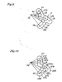
- FIGS. 1 and 6-8 as a structure preferable for the supporting structure for a shield acting as the turning opening or closing member, it is possible to illustrate that there is provided an arc part (U') at any one of the helmet and the turning opening or closing member, a first guide shaft (S'1) and a second guide shaft (S'2) slidably engaged to the arc part (U') at the other of the helmet and the turning opening or closing member, turning of the turning opening or closing member is cooperatively controlled by these arc parts and the two guide shafts;
- a first engaging part (U'1) with an arc shape having a center of arc outside the arc parts (U'), a second engaging part (U'2) with an arc shape having a center of arc inside the arc parts (U') are integrally and cooperatively arranged, each of the centers of arc is coaxial with the center of turning of the turning opening or closing member and the turning opening or closing member is turned along an orbit of the arc
- each of the engaging parts may be formed of either a hole or a groove if each of the guide shafts is engaged with it.
- the first engaging part (U1), the second engaging part (U2) and the third engaging part (U3) are of a grooved shape; the second engaging part (U2) and the third engaging part (U3) of the grooved shape are provided with a step difference, and each of the shafts is not displaced to the other engaging part except at a crossing part of both engaging parts. (Claim 4)
- the first engaging part (U'1) and the second engaging part (U'2) are of a grooved shape; and the first engaging part (U'1) and the second engaging part (U'2) of the grooved shape are provided with a step difference, and each of the shafts is not displaced to the other engaging part also at a crossing part of both engaging parts. (Claim 5)
- the aforesaid one illustrated above is an embodiment in which there are provided two centers of turning of the turning opening or closing member.
- the present invention is not restricted or limited to this embodiment.
- the present invention includes also an embodiment in which more than two centers of turning are provided while the center of turning is moved during the turning operation of the engaging parts as found in the engaging part (FIG. 9) including arcs having different curvatures or the engaging part (FIG. 10) having lines connected to each other through a curved part of a certain angle.
- FIGS. 1 and 2 illustrate a full-face helmet A, and the full-face helmet A is provided with a ventilation hole A2 opened or closed by a chin-ventilation 1, and with a shield 4 for opening or closing a front opening part A4.
- the chin-ventilation 1 is rotatably supported at a chin-ventilation supporter 2 passed through and fixed to a chin guard part A1 of a helmet B.
- the chin-ventilation supporter 2 includes a ventilating hole 3 that is opened and closed by the chin-ventilation 1 and attached to a through hole A3 that is opened by the chin guard part A1, and the surface thereof is formed as a single face to the chin guard part A1.
- the chin-ventilation 1 is constructed such that it is rotatably supported at the chin-ventilation supporter 2 by an operating mechanism constituted by engaging the first guide shaft S1 and the second guide shaft S2 arranged at each of the right and left sides of the chin-ventilation supporter 2 with the arc parts U formed at each of the right and left sides of the chin-ventilation main body 11 (refer to FIGS. 2 to 4).
- the arc parts U in the chin-ventilation 1 are made such that the first arcuate engaging part U1, the second arcuate engaging part U2 and the third arcuate engaging part U3 are integrally and cooperatively arranged; the arcs of the first engaging part U1 and the third engaging part U3 have a common center point outside the operating mechanism (hereinafter called as the first center point P1); an arc of the second engaging part U2 has a center point inside the arc parts U (within the operating mechanism) (hereinafter called as the second center point P2); and an opening or closing operation of the chin-ventilation 1 is carried out while it is being switched over to the first center point P1 and the second center point P2 (refer to FIG. 5).
- first engaging part U1 to the third engaging part U3 are provided with holes at the supporting plates 1L, 1R integrally formed at the right and left sides of the chin-ventilation main body 11.
- first guide shaft S1 and the second guide shaft S2 are protruded and formed at the supporting plates 3L, 3R integrally formed to be faced against the supporting plates 1L, 1R at the right and left sides of the ventilation hole 3.
- a structure where the center of turning operation of the chin-ventilation 1 during its opening or closing operation is switched over will be described in detail, wherein the first engaging part U1 and the third engaging part U3 at first draw arcs C1, C2 having different diameters around the turning center point P1 during the opening operation from the closed state of the chin-ventilation 1 as shown in FIG. 5, respectively, and it is switched from the first turning center point P1 to the second turning center point P2 coaxial with the second guide shaft S2 during the opening operation of the chin-ventilation 1, and further the second engaging part U2 is formed into a shape to draw the arc C3 with the second turning center point P2 being applied as the turning center point during the opening operation after being switched over.
- the first engaging part U1 and the second engaging part U2 are linked in a point in which the first central point P1 is switched to the second central point P2.
- a position in which the central point is switched is a position in which a curved portion U11 of the first engaging part U1 touches the first guide shaft S1 on the way to which the chin-ventilation 1 is turned, it is ended to turn about the turning central portion of the first central point P1, and also an end portion U31 of the third engaging part U3 touches the second guide shaft S2. (refer to FIG. 5(c))
- the starting portion U12 of the first engaging part U1 touches the first guide shaft S1 and the second guide shaft S2 is positioned in a position (a starting portion U32 of the third engaging part U3) where the second engaging part U2 and the third engaging part U3 cross with each other.
- the chin-ventilation 1 turns around the turning center point of the first turning center point P1 in such a way that the first engaging part U1 and the third engaging part U3 are guided by the first guide shaft S1 and the second guide shaft S2 to draw the arcs C1, C2.
- the chin-ventilation 1 is operated such that the bent part U11 of the first engaging part U1 is contacted with the first guide shaft S1 and the terminal end part U31 of the third engaging part U3 is contacted with the second guide shaft S2 at the position illustrated in FIG. 5(c), thereby the turning center point is switched from the first turning center point P1 to the second turning center point P2.
- the chin-ventilation 1 When the chin-ventilation 1 is opened from this position, the chin-ventilation 1 is operated such that the second engaging part U2 is guided by the first guide shaft S1 with the second turning center point P2 being applied as the turning center point to draw the arc C3 as illustrated in FIG. 5(d).
- the front end of the chin-ventilation 1 is not protruded so much from the surface of the chin-ventilation supporting part 2 in an outward direction under its full-opened state, and further an entire region of the ventilation hole 3 can be opened.
- the shield 4 is rotatably supported at the right and left side surfaces of the helmet B.
- the shield 4 is constructed such that it is rotatably supported by the operating mechanism constituted while the first guide shaft S'1 and the second guide shaft S'2 arranged at the helmet B are being engaged to the arc parts U' formed at the right and left ends of the shield.
- the base plates are installed at the right and left side surfaces of the helmet, the first guide shaft S'1 and the second guide shaft S'2 are arranged on the base plate, the shield 4 is supported by the shafts and further the supporting structure is hidden by covering it with the shield cover.
- the arc part U' in the shield is made such that the arcuate first engaging part U'1 and arcuate second engaging part U'2 are integrally arranged, the center point of the arc of the first engaging part U'1 is applied as the first center point P'1 set outside the operating mechanism, the center point of the arc of the second engaging part U'2 is applied as the second center point P'2 set inside the arc parts U' (within the operating mechanism), and the opening or closing operation of the shield 4 is carried out while it is being switched over the first center point P'1 and the second center point P'2 (refer to FIGS. 6 to 8).
- the first engaging part U'1 draws an arc C'1 with the first turning center point P'1 being applied as the turning center during the opening operation performed from the closed state of the shield 4, the turning center point is switched over from the first turning center point P'1 to the second turning center point P'2 coaxial with the second guide shaft S'2 during the opening operation, and the second engaging part U'2 is formed to draw the arc C'2 with the second turning center point P'2 being applied as the turning center point.
- the first engaging part U'1 and the second engaging part U'2 are cooperatively arranged at a position where it is switched from the first turning center point P'1 to the second turning center point P'2.
- the position where the center points are switched over corresponds to a position where an end part at the second guide shaft S'2 in the first engaging part U'1 (hereinafter called as “the terminal end part U'11" and an opposite end part is called as “the starting end part U'12") is contacted with the second guide shaft S'2 during the turning operation of the shield 4 and the turning is stopped with the first turning center point P'1 being applied as the turning center point and at this time, the end part U'21 (a cooperative part with the first engaging part U'1) of the second engaging part U'2 is accurately opposing against the second guide shaft S'2 (refer to FIG. 7(b)).
- FIG. 1 and FIGS. 6 to 8 an opening or closing operation of the shield 4 under an operation of the supporting structure as described above will be described.
- the shield 4 is closely contacted with a rimmed rubber A5 of the opening part A4 of the helmet B.
- the shield 4 when the shield 4 is opened from its full-closed state, the shield is operated such that the first engaging part U'1 is guided by the guide shaft G'1 with the first turning center point P'1b being applied as the turning center point to draw the arc C'1 and as shown in FIG. 7(b), the terminal end U'11 of the first engaging part U'1 is contacted with the second guide shaft S'1, thereby the turning center point is switched from the first turning center point P'1 to the second turning center point P'2.
- the shield 4 is turned to move away from the rimmed rubber A5.
- the shield 4 occupies the state where it is approached to the surface of the helmet B.
- the shield 4 is closely contacted with the rimmed rubber A5 under its full-closed state and the shield 4 can be approached to the surface of the helmet B under its full-opened state.
- FIGS. 9 and 10 explain each case that two or more turning center points are provided in the mouth shutter 1.
- engaging parts of FIG. 9 are defined as the first engaging part U10, the second engaging part U20, and the third engaging part U30 respectively.
- Engaging parts of FIG. 10 are defined as the first engaging part U10', the second engaging part U20', and the third engaging part U30' respectively.
- each curvature of the arc of the engaging part changes at a halfway point and each turning center point for turning along the arc having different curvature exist.
- the radius of arcs C5, C5' at the aforementioned halfway turning center point to the end portion is lengthened than arcs C4, C4' at the starting portion to the halfway turning center point.
- the position of the first central point P3 as the turning center point of arcs C4, C4' is different from the second central point P4 as the turning center point of arcs C5, C5'.
- the turning center point of the arcs C4, C4' is the first central point P3.
- the turning center point moves to the second central point P4 from the first central point P3 gradually, thus it is switched to the second central point P4.
- the turning center points of the chin-ventilation of the aforementioned embodiment have three points, such as the first, second, and third center point, and plural center points existing between the first central point P3 and the second central point P4. It is also possible to embody a structure in which there exist three or more turning center points.
- the embodiments of the first engaging part U10', the second engaging part U20', and the third engaging part U30' of FIG. 10 have a form structured by connecting plural straight lines ST1 to ST9 by way of each shape's curved portion.
- This structure is made such that the turning operation is regulated at the time that each guide shaft touches the curved portion in turning operation of the chin-ventilation. Using this regulation, a ratchet function comes to be effective to the operation of opening the chin-ventilation.
- the chin-ventilation cannot move as a turning movement since the chin-ventilation moves along each straight line, but the chin-ventilation performs the movement nearly the same as the turning movement in view of the whole movement of the chin-ventilation.
- the embodiment of the present invention has two or more turning center points.
- first engaging part U1 and the second engaging part U2 of the aforementioned embodiment are explained as through holes, it is possible for the present invention to have a channel structure arbitrarily as shown in FIG. 11.
- reference characters U1', U2' and U3' are used to the first engaging part, the second engaging part, and the third engaging part of the present invention respectively.
- reference characters S1' and S2' are used to the first guide shaft and the second guide shaft respectively.
- first engaging part U1', the second engaging part U2', and the third engaging part U3' are totally the same as the first engaging part U1, the second engaging part U2, and the third engaging part U3 respectively.
- the height position of the bottom face U3 of the third engaging part U3' is positioned in one step lower position than the bottom face U4 of the first engaging part U1' and the second engaging part U2'. Accordingly, a wall face type step difference W is formed around the third engaging part U3'.
- the first guide shaft S1' has an approaching length to a bottom portion U4 of the first engaging part U1'.
- the second guide shaft S2' has an approaching length to the bottom portion U3 of the third engaging part U3'.
- the second guide shaft S2' is held by the aforementioned step difference W and it is kept to be securely engaged to the inside of the third engaging part U3'.
- the whole area of the ventilating hole 3 can be opened without letting the top end portion of the chin-ventilation 1 protrude in the outer direction from the surface of the chin-ventilation supporter 2.
- the second guide shaft S2' can be maintained in the third engaging part U3' more securely by the step difference W.
- FIGS. 9 to 11 can be applied to the chin-ventilation structure for the shield shown in FIGS. 6 to 8.
- the chin-ventilation structure for the turning opening or closing member of the present invention can also be used as the chin-ventilation support structure for the chin-ventilation and the supporting structure for the shield.
- the supporting structure can be easily formed even in such a small member as the chin-ventilation and further the turning of the shield in compliance with the shape of the helmet can be carried out.
- the supporting structures for the chin-ventilation and the shield are effective.
- the turning opening or closing member is a chin-ventilation
- the front end of the chin-ventilation is not protruded so much outwardly from the surface of the chin-ventilation supporting part and further a substantial entire region of the ventilation hole can be opened.
- the shield can be held under its full-opened state to a state where it is approached to the surface of the helmet.
- the turning center point of the shield is switched from the midway part of the opening operation while the shield avoiding the protruded member at the beginning of the opening operation and it is approached to the surface of the helmet under its full-closed state.
- the full-open angle of the shield can be set in compliance with an angle of the flange, so that when the shield is raised, it can be easily stored and held inside the flange.
- the supporting structure of the present invention can realize the turning operation of the shield in compliance with the shape of the helmet.
- the engaged state of the guide shafts into the engaged parts is held more positively due to the step difference in addition to the aforesaid effect, so that the present invention has a quite superior effect in view of performing the positive turning and guiding of the turning opening or closing member without causing the guide shafts to be displaced from the engaging part at the time of opening or closing operation of the turning opening or closing member.
Landscapes
- Helmets And Other Head Coverings (AREA)
Claims (5)
- Anordnung zur Halterung eines schwenkbaren Öffnungs- oder Schließelements eines Helmes, d.h. ein Element, das unter seiner Schwenkung geöffnet oder geschlossen wird, wie z.B. ein Verschluss (1) oder ein Visier (4), bei dem
ein Betätigungsmechanismus für das Element über einem Helm und dem Element bereitgestellt ist; dadurch gekennzeichnet, dass
der genannte Betätigungsmechanismus eine Mehrzahl von Bogenteilen (U1, U2; U'1, U'2) zur Verwendung beim Steuern einer Schwenkung des Elements (1; 4) am Helm oder am Element aufweist;
die genannten Bogenteile so ausgebildet sind, dass eine Mehrzahl von mehr als zwei Bögen, die jeweils verschiedene Bogenmitten haben, kooperativ einstückig angeordnet sind, wenigstens einer der Bögen eine Bogenmitte außerhalb des Betätigungsmechanismus hat, jede der Bogenmitten einschließlich dieser Bogenmitte während des Öffnungs- oder Schließvorgangs des Elements mit seiner Drehungsmitte koaxial ist und das Element entlang einer Bahn jedes der Bögen geschwenkt wird; und wodurch
das Element entlang der Bahn jedes der genannten Bögen geschwenkt wird, während die genannte Drehungsmitte während seines Öffnungs- oder Schließvorgangs gewechselt wird. - Anordnung nach Anspruch 1, bei der
das schwenkbare Öffnungs- oder Schließelement eine Kinnlüftung ist; dadurch gekennzeichnet, dass
ein erster Führungsschaft (S1) und ein zweiter Führungsschaft (S2) am Helm oder am Element angeordnet sind, um gleitfähig mit den Bogenteilen (U) am Element bzw. am Helm in Eingriff zu sein, so dass das Schwenken des Elements von den Bogenteilen (U) und den beiden Führungsschäften kooperativ gesteuert wird;
die genannten Bogenteile (U) einen ersten Eingriffsteil (U1) mit einer Bogenform, die eine Bogenmitte außerhalb des Betätigungsmechanismus hat, einen zweiten Eingriffsteil (U2) mit einer Bogenform, die eine Bogenmitte innerhalb des Betätigungsmechanismus hat, und einen dritten Eingriffsteil (U3) mit einer Bogenform, die eine Bogenmitte gemeinsam mit der des genannten ersten Eingriffsteils (U1) hat, aufweisen, einstückig und kooperativ angeordnet sind;
jede der Bogenmitten mit der Drehungsmitte des Elements koaxial ist, damit das genannte Element entlang einer Bahn des Bogens von jedem der Eingriffsteile geschwenkt werden kann;
die Eingriffsteile (U1, U2 und U3) so angeordnet sind, dass zu Beginn des Öffnungsvorgangs des Elements das Element um die Drehungsmitte des ersten Mittelpunkts (P 1) geführt werden kann, die eine gemeinsame Bogenmitte ist, die bei einem Zusammenwirken des ersten Führungsschaftes (S1), des ersten Eingriffsteils (U1), des zweiten Führungsschaftes (S2) und des dritten Eingriffsteils (U3) zu beiden Eingriffsteilen gehört; und
wenn der erste Führungsschaft (S1) während des Öffnungsvorgangs einen Verbindungspunkt zwischen dem ersten Eingriffsteil (U1) und dem zweiten Eingriffsteil (U2) erreicht, kann die Mitte des zweiten Führungsschaftes (S2) einen zweiten Mittelpunkt (P2) der zum zweiten Eingriffsteil (U2) gehörenden Bogenmitte erreichen und gleichzeitig wechselt die Drehungsmitte des Elements von dem genannten ersten Mittelpunkt (P 1) zum zweiten Mittelpunkt (P2) zum Schwenken um den zweiten Führungsschaft (S2). - Anordnung nach Anspruch 1, bei der
das schwenkbare Öffnungs- oder Schließelement ein Visier ist;
dadurch gekennzeichnet, dass
ein erster Führungsschaft (S1) und ein zweiter Führungsschaft (S2) am Helm oder am Element angeordnet sind, um gleitfähig mit Bogenteilen (U) am Element bzw. am Helm in Eingriff zu sein, so dass das Schwenken des Elements von diesen Bogenteilen (U) und den beiden Führungsschäften kooperativ gesteuert wird;
die genannten Bogenteile (U') einen ersten Eingriffsteil (U'1) mit einer Bogenform, die eine Bogenmitte außerhalb des Betätigungsmechanismus hat, einen zweiten Eingriffsteil (U'2) mit einer Bogenform, die eine Bogenmitte innerhalb des Betätigungsmechanismus hat, aufweisen und einstückig und kooperativ angeordnet sind, wobei jede der Bogenmitten mit der Drehungsmitte des Elements koaxial ist, damit das genannte Element entlang einer Bahn des Bogens von jedem der Eingriffsteile geschwenkt werden kann;
die Eingriffsteile (U'1, U'2) so angeordnet sind, dass zu Beginn des Öffnungsvorgangs des Elements das Element um die Drehungsmitte des ersten Mittelpunkts (P'1) geführt werden kann, die die Bogenmitte ist, die bei einem Zusammenwirken des ersten Führungsschaftes (S'1), des zweiten Führungsschaftes (S'2) und des ersten Eingriffsteils (U'1) zum ersten Eingriffsteil (U'1) gehört; und
wenn der erste Führungsschaft (S'1) während des Öffnungsvorgangs einen Verbindungspunkt zwischen dem ersten Eingriffsteil (U'1) und dem zweiten Eingriffsteil (U'2) erreicht, die Mitte des zweiten Führungsschaftes (S'2) einen zweiten Mittelpunkt (P'2) der zum zweiten Eingriffsteil (U'2) gehörenden Bogenmitte erreichen kann und gleichzeitig die Drehungsmitte des Elements von dem genannten ersten Mittelpunkt (P'1) zum zweiten Mittelpunkt (P'2) gewechselt werden kann zum Schwenken um den zweiten Führungsschaft (S'2). - Anordnung nach Anspruch 2, dadurch gekennzeichnet, dass
der erste Eingriffsteil (U1), der zweite Eingriffsteil (U2) und der dritte Eingriffsteil (U3) eine ausgesparte Gestalt haben;
der zweite Eingriffsteil (U2) und der dritte Eingriffsteil (U3) mit der ausgesparten Gestalt mit einer Absatz- oder Höhendifferenz versehen sind, so dass jeder der Schäfte in dem Eingriffsteil (U2, U3) gehalten wird und die Schäfte nicht zum anderen Eingriffsteil verschoben werden, außer an einem Kreuzungsteil beider Eingriffsteile. - Anordnung nach Anspruch 3, dadurch gekennzeichnet, dass
der erste Eingriffsteil (U'1) und der zweite Eingriffsteil (U'2) eine ausgesparte Gestalt haben;
der erste Eingriffsteil (U'1) und der zweite Eingriffsteil (U'2) mit der ausgesparten Gestalt mit einer Absatz- oder Höhendifferenz versehen sind, so dass jeder der Schäfte in den Eingriffsteilen U'1, U'2) gehalten wird und die Schäfte nicht zum anderen Eingriffsteil verschoben werden, außer an einem Kreuzungsteil beider Eingriffsteile.
Applications Claiming Priority (4)
| Application Number | Priority Date | Filing Date | Title |
|---|---|---|---|
| JP2002221424 | 2002-07-30 | ||
| JP2002221424 | 2002-07-30 | ||
| JP2003130955A JP3875650B2 (ja) | 2002-07-30 | 2003-05-09 | フルフェースヘルメットにおけるマウスシャッタの支持構造 |
| JP2003130955 | 2003-05-09 |
Publications (2)
| Publication Number | Publication Date |
|---|---|
| EP1386550A1 EP1386550A1 (de) | 2004-02-04 |
| EP1386550B1 true EP1386550B1 (de) | 2007-09-05 |
Family
ID=30117499
Family Applications (1)
| Application Number | Title | Priority Date | Filing Date |
|---|---|---|---|
| EP03254425A Expired - Lifetime EP1386550B1 (de) | 2002-07-30 | 2003-07-12 | Helm mit Vorrichtung zur Halterung eines schwenbaren Verschluss- oder Öffnungsteil |
Country Status (8)
| Country | Link |
|---|---|
| US (1) | US6931670B2 (de) |
| EP (1) | EP1386550B1 (de) |
| JP (1) | JP3875650B2 (de) |
| KR (1) | KR100961504B1 (de) |
| CN (1) | CN1475175B (de) |
| AT (1) | ATE372067T1 (de) |
| DE (1) | DE60316079T2 (de) |
| TW (1) | TWI261501B (de) |
Families Citing this family (17)
| Publication number | Priority date | Publication date | Assignee | Title |
|---|---|---|---|---|
| KR100895454B1 (ko) * | 2002-07-30 | 2009-05-07 | 가부시키가이샤 아라이 헬멧 | 풀페이스 헬멧에 있어서의 마우스셔터의 지지구조 |
| EP2076149B1 (de) | 2006-10-13 | 2013-05-22 | The University Of British Columbia | Vorrichtung zur milderung von rückenmarksverletzungen |
| US7895678B2 (en) * | 2007-08-06 | 2011-03-01 | Bell Sports, Inc. | Helmet with improved shield mount and precision shield control |
| KR100875460B1 (ko) * | 2007-10-18 | 2008-12-22 | 주식회사 홍진에이치제이씨 | 헬멧용 턱 보호대 개폐 장치 |
| US20090113607A1 (en) * | 2007-11-02 | 2009-05-07 | Yao-Gwo Gan | Connection of goggle and mask |
| FR2986141B1 (fr) * | 2012-01-26 | 2015-03-27 | Msa Gallet | Casque de protection equipe d’un ecran facial mobile |
| CN102871258B (zh) * | 2012-09-29 | 2014-12-31 | 江门市鹏程头盔有限公司 | 一种可变护颚结构型头盔 |
| JP6173128B2 (ja) * | 2013-08-28 | 2017-08-02 | 株式会社アライヘルメット | ヘルメットにおけるシールドの支持構造 |
| US10154704B1 (en) * | 2015-04-17 | 2018-12-18 | Desmark Industries, Inc. | Helmet slide assembly |
| MX2017014780A (es) * | 2015-05-19 | 2018-08-09 | Paranhos Torres Mauricio | Mejoras en celda de proteccion craneal. |
| WO2017192477A1 (en) | 2016-05-02 | 2017-11-09 | Affera, Inc. | Method of inserting a catheter with an expandable tip and a system comprising a catheter, a sheath and an insertion sleeve |
| US10869521B2 (en) * | 2016-10-14 | 2020-12-22 | Kido Sports Co., Ltd. | Helmet |
| US11134741B2 (en) * | 2017-05-25 | 2021-10-05 | E.D. Bullard Company | Protective helmet with a retractable and removable visor |
| FR3117743B1 (fr) * | 2020-12-23 | 2022-11-25 | Technowill | Casque de sûreté à barbe articulée |
| TWI740798B (zh) * | 2021-04-13 | 2021-09-21 | 廣權精密有限公司 | 帽體之鏡片樞組結構 |
| FR3143278B1 (fr) * | 2022-12-16 | 2024-11-29 | Shark | Casque de protection convertible avec mécanisme de guidage amélioré de la mentonnière |
| US20250160468A1 (en) * | 2023-11-22 | 2025-05-22 | Bell Sports, Inc. | Helmet comprising a ventilation system |
Family Cites Families (16)
| Publication number | Priority date | Publication date | Assignee | Title |
|---|---|---|---|---|
| US3727235A (en) * | 1972-01-13 | 1973-04-17 | Ilc Ind Inc | Retractable face protective assembly |
| DE3006596A1 (de) * | 1979-02-26 | 1980-09-04 | Kangol Helmets Ltd | Schutzhelm |
| IT8123588U1 (it) * | 1981-11-20 | 1983-05-20 | Essepi Srl | Cerniera per visiera ad incasso di caschi protettivi, in particolare per motociclisti. |
| DE3441078A1 (de) * | 1984-09-18 | 1986-03-27 | Föhl, Artur, 7060 Schorndorf | Sicherheitshelm, insbesondere sturzhelm |
| CN1006357B (zh) * | 1984-11-09 | 1990-01-10 | 阿图尔·福尔 | 安全帽,尤其是头盔 |
| JPS61174406A (ja) | 1985-01-24 | 1986-08-06 | 昭栄化工株式会社 | ヘルメツトのシ−ルド板装置 |
| FR2595921A1 (fr) * | 1986-03-18 | 1987-09-25 | Gpa Int | Casque a ecran integrable dans sa coque |
| EP0258496B1 (de) * | 1986-08-01 | 1990-06-13 | T.A.C. Tongerese Automaten Centrale personenvennootschap met beperkte aansprakelijkheid | Schutzhelm |
| GB8705452D0 (en) * | 1987-03-09 | 1987-04-15 | Gec Avionics | Headgear |
| JPH01174406A (ja) | 1987-12-28 | 1989-07-11 | Tanaka Seishi Kogyo Kk | セラミック製品の製造方法 |
| FR2637468B3 (fr) * | 1988-08-30 | 1990-12-21 | Chaise Francois | Casque de protection equipe d'un ecran de vision au mouvement de relevage automatique et amorti |
| GB9200833D0 (en) * | 1992-01-15 | 1992-03-11 | Ayres David | Visor assembly |
| FR2724541B1 (fr) * | 1994-09-20 | 1996-12-06 | Sextant Avionique | Paire d'articulations a manoeuvres synchronisees pour la fixation d'une visiere escamotable sur un casque |
| JP2878262B1 (ja) | 1998-03-05 | 1999-04-05 | 株式会社アライヘルメット | ヘルメットにおけるシールドの開閉機構 |
| US6047409A (en) * | 1998-05-02 | 2000-04-11 | Simpson; Elwood J. B. | Adjustable safety lock for helmet face shield |
| IT1318799B1 (it) | 2000-08-31 | 2003-09-10 | Project Srl | Sistema di aggancio della mentoniera di un casco apribile |
-
2003
- 2003-05-09 JP JP2003130955A patent/JP3875650B2/ja not_active Expired - Fee Related
- 2003-07-01 TW TW092117934A patent/TWI261501B/zh not_active IP Right Cessation
- 2003-07-12 AT AT03254425T patent/ATE372067T1/de not_active IP Right Cessation
- 2003-07-12 EP EP03254425A patent/EP1386550B1/de not_active Expired - Lifetime
- 2003-07-12 DE DE60316079T patent/DE60316079T2/de not_active Expired - Lifetime
- 2003-07-29 US US10/628,429 patent/US6931670B2/en not_active Expired - Lifetime
- 2003-07-29 CN CN031523323A patent/CN1475175B/zh not_active Expired - Fee Related
- 2003-07-30 KR KR1020030052621A patent/KR100961504B1/ko not_active Expired - Fee Related
Also Published As
| Publication number | Publication date |
|---|---|
| TWI261501B (en) | 2006-09-11 |
| JP3875650B2 (ja) | 2007-01-31 |
| TW200401614A (en) | 2004-02-01 |
| DE60316079D1 (de) | 2007-10-18 |
| US6931670B2 (en) | 2005-08-23 |
| KR100961504B1 (ko) | 2010-06-08 |
| ATE372067T1 (de) | 2007-09-15 |
| EP1386550A1 (de) | 2004-02-04 |
| US20040019956A1 (en) | 2004-02-05 |
| CN1475175B (zh) | 2010-05-26 |
| KR20040011392A (ko) | 2004-02-05 |
| DE60316079T2 (de) | 2008-05-29 |
| JP2004124346A (ja) | 2004-04-22 |
| CN1475175A (zh) | 2004-02-18 |
Similar Documents
| Publication | Publication Date | Title |
|---|---|---|
| EP1386550B1 (de) | Helm mit Vorrichtung zur Halterung eines schwenbaren Verschluss- oder Öffnungsteil | |
| EP1241054B1 (de) | Kabelbaumanordnung für eine Kraftfahrzeugschiebetür | |
| EP1245165B1 (de) | Vorrichtung zum Befestigen einer Visierscheibe an einem Helm | |
| AU754311B2 (en) | Crash-helmet with device for locking and releasing movable parts | |
| US10660392B2 (en) | Helmet | |
| US6928697B2 (en) | Hinge | |
| EP1106764B9 (de) | Fensterbeschlag | |
| US6581238B1 (en) | Motor vehicle wiper | |
| EP1386551A1 (de) | Vorrichtung zur Halterung einer im Kinnbügel angeordneten Lüftungsklappe für Integralhelm | |
| JPH09164845A (ja) | 自動車の摺動ドアのレールの保護装置 | |
| JP2008516095A (ja) | 保護ヘルメット | |
| JP7254129B2 (ja) | ヘルメットのシールド枢着構造 | |
| KR102588817B1 (ko) | 에어벤트의 윙 노브 장치 | |
| KR100328985B1 (ko) | 차량용 쿼터 글래스 개폐 장치 | |
| KR100214968B1 (ko) | 차량의 에어벤트 댐퍼 개폐장치 | |
| WO1996024265A1 (en) | Helmet visor mechanism with laterally moveable visors | |
| JP3298749B2 (ja) | 自動車用レジスタ | |
| JP2001158226A (ja) | 風向調整装置 | |
| KR20230022023A (ko) | 자동차 에어벤트의 프론트윙 장치 | |
| JPH031575Y2 (de) | ||
| JP4461744B2 (ja) | リクライニング装置用シールドおよびこのシールドを備えた車両用シート | |
| JPH0426269Y2 (de) | ||
| JP2000297961A (ja) | 風向調整装置 | |
| JP4659284B2 (ja) | シャッタカーテンの構造 | |
| KR20230022024A (ko) | 자동차 에어벤트의 프론트윙 장치 |
Legal Events
| Date | Code | Title | Description |
|---|---|---|---|
| PUAI | Public reference made under article 153(3) epc to a published international application that has entered the european phase |
Free format text: ORIGINAL CODE: 0009012 |
|
| AK | Designated contracting states |
Kind code of ref document: A1 Designated state(s): AT BE BG CH CY CZ DE DK EE ES FI FR GB GR HU IE IT LI LU MC NL PT RO SE SI SK TR |
|
| AX | Request for extension of the european patent |
Extension state: AL LT LV MK |
|
| 17P | Request for examination filed |
Effective date: 20040329 |
|
| AKX | Designation fees paid |
Designated state(s): AT BE BG CH CY CZ DE DK EE ES FI FR GB GR HU IE IT LI LU MC NL PT RO SE SI SK TR |
|
| GRAP | Despatch of communication of intention to grant a patent |
Free format text: ORIGINAL CODE: EPIDOSNIGR1 |
|
| GRAS | Grant fee paid |
Free format text: ORIGINAL CODE: EPIDOSNIGR3 |
|
| GRAA | (expected) grant |
Free format text: ORIGINAL CODE: 0009210 |
|
| AK | Designated contracting states |
Kind code of ref document: B1 Designated state(s): AT BE BG CH CY CZ DE DK EE ES FI FR GB GR HU IE IT LI LU MC NL PT RO SE SI SK TR |
|
| REG | Reference to a national code |
Ref country code: GB Ref legal event code: FG4D |
|
| REG | Reference to a national code |
Ref country code: CH Ref legal event code: EP Ref country code: CH Ref legal event code: NV Representative=s name: ABREMA AGENCE BREVET ET MARQUES, GANGUILLET |
|
| REF | Corresponds to: |
Ref document number: 60316079 Country of ref document: DE Date of ref document: 20071018 Kind code of ref document: P |
|
| REG | Reference to a national code |
Ref country code: IE Ref legal event code: FG4D |
|
| REG | Reference to a national code |
Ref country code: SE Ref legal event code: TRGR |
|
| ET | Fr: translation filed | ||
| PG25 | Lapsed in a contracting state [announced via postgrant information from national office to epo] |
Ref country code: FI Free format text: LAPSE BECAUSE OF FAILURE TO SUBMIT A TRANSLATION OF THE DESCRIPTION OR TO PAY THE FEE WITHIN THE PRESCRIBED TIME-LIMIT Effective date: 20070905 Ref country code: ES Free format text: LAPSE BECAUSE OF FAILURE TO SUBMIT A TRANSLATION OF THE DESCRIPTION OR TO PAY THE FEE WITHIN THE PRESCRIBED TIME-LIMIT Effective date: 20071216 |
|
| PG25 | Lapsed in a contracting state [announced via postgrant information from national office to epo] |
Ref country code: AT Free format text: LAPSE BECAUSE OF FAILURE TO SUBMIT A TRANSLATION OF THE DESCRIPTION OR TO PAY THE FEE WITHIN THE PRESCRIBED TIME-LIMIT Effective date: 20070905 |
|
| PG25 | Lapsed in a contracting state [announced via postgrant information from national office to epo] |
Ref country code: GR Free format text: LAPSE BECAUSE OF FAILURE TO SUBMIT A TRANSLATION OF THE DESCRIPTION OR TO PAY THE FEE WITHIN THE PRESCRIBED TIME-LIMIT Effective date: 20071206 |
|
| PG25 | Lapsed in a contracting state [announced via postgrant information from national office to epo] |
Ref country code: CZ Free format text: LAPSE BECAUSE OF FAILURE TO SUBMIT A TRANSLATION OF THE DESCRIPTION OR TO PAY THE FEE WITHIN THE PRESCRIBED TIME-LIMIT Effective date: 20070905 Ref country code: PT Free format text: LAPSE BECAUSE OF FAILURE TO SUBMIT A TRANSLATION OF THE DESCRIPTION OR TO PAY THE FEE WITHIN THE PRESCRIBED TIME-LIMIT Effective date: 20080206 Ref country code: SK Free format text: LAPSE BECAUSE OF FAILURE TO SUBMIT A TRANSLATION OF THE DESCRIPTION OR TO PAY THE FEE WITHIN THE PRESCRIBED TIME-LIMIT Effective date: 20070905 |
|
| PG25 | Lapsed in a contracting state [announced via postgrant information from national office to epo] |
Ref country code: RO Free format text: LAPSE BECAUSE OF FAILURE TO SUBMIT A TRANSLATION OF THE DESCRIPTION OR TO PAY THE FEE WITHIN THE PRESCRIBED TIME-LIMIT Effective date: 20070905 |
|
| PLBE | No opposition filed within time limit |
Free format text: ORIGINAL CODE: 0009261 |
|
| STAA | Information on the status of an ep patent application or granted ep patent |
Free format text: STATUS: NO OPPOSITION FILED WITHIN TIME LIMIT |
|
| PG25 | Lapsed in a contracting state [announced via postgrant information from national office to epo] |
Ref country code: DK Free format text: LAPSE BECAUSE OF FAILURE TO SUBMIT A TRANSLATION OF THE DESCRIPTION OR TO PAY THE FEE WITHIN THE PRESCRIBED TIME-LIMIT Effective date: 20070905 |
|
| 26N | No opposition filed |
Effective date: 20080606 |
|
| PG25 | Lapsed in a contracting state [announced via postgrant information from national office to epo] |
Ref country code: MC Free format text: LAPSE BECAUSE OF NON-PAYMENT OF DUE FEES Effective date: 20080731 |
|
| PG25 | Lapsed in a contracting state [announced via postgrant information from national office to epo] |
Ref country code: EE Free format text: LAPSE BECAUSE OF FAILURE TO SUBMIT A TRANSLATION OF THE DESCRIPTION OR TO PAY THE FEE WITHIN THE PRESCRIBED TIME-LIMIT Effective date: 20070905 |
|
| PG25 | Lapsed in a contracting state [announced via postgrant information from national office to epo] |
Ref country code: SI Free format text: LAPSE BECAUSE OF FAILURE TO SUBMIT A TRANSLATION OF THE DESCRIPTION OR TO PAY THE FEE WITHIN THE PRESCRIBED TIME-LIMIT Effective date: 20070905 |
|
| PG25 | Lapsed in a contracting state [announced via postgrant information from national office to epo] |
Ref country code: CY Free format text: LAPSE BECAUSE OF FAILURE TO SUBMIT A TRANSLATION OF THE DESCRIPTION OR TO PAY THE FEE WITHIN THE PRESCRIBED TIME-LIMIT Effective date: 20070905 Ref country code: IE Free format text: LAPSE BECAUSE OF NON-PAYMENT OF DUE FEES Effective date: 20080714 |
|
| PG25 | Lapsed in a contracting state [announced via postgrant information from national office to epo] |
Ref country code: BG Free format text: LAPSE BECAUSE OF FAILURE TO SUBMIT A TRANSLATION OF THE DESCRIPTION OR TO PAY THE FEE WITHIN THE PRESCRIBED TIME-LIMIT Effective date: 20071205 |
|
| PG25 | Lapsed in a contracting state [announced via postgrant information from national office to epo] |
Ref country code: HU Free format text: LAPSE BECAUSE OF FAILURE TO SUBMIT A TRANSLATION OF THE DESCRIPTION OR TO PAY THE FEE WITHIN THE PRESCRIBED TIME-LIMIT Effective date: 20080306 Ref country code: LU Free format text: LAPSE BECAUSE OF NON-PAYMENT OF DUE FEES Effective date: 20080712 |
|
| PG25 | Lapsed in a contracting state [announced via postgrant information from national office to epo] |
Ref country code: TR Free format text: LAPSE BECAUSE OF FAILURE TO SUBMIT A TRANSLATION OF THE DESCRIPTION OR TO PAY THE FEE WITHIN THE PRESCRIBED TIME-LIMIT Effective date: 20070905 |
|
| PGFP | Annual fee paid to national office [announced via postgrant information from national office to epo] |
Ref country code: DE Payment date: 20140721 Year of fee payment: 12 Ref country code: NL Payment date: 20140721 Year of fee payment: 12 Ref country code: CH Payment date: 20140721 Year of fee payment: 12 |
|
| PGFP | Annual fee paid to national office [announced via postgrant information from national office to epo] |
Ref country code: FR Payment date: 20140721 Year of fee payment: 12 Ref country code: GB Payment date: 20140721 Year of fee payment: 12 Ref country code: SE Payment date: 20140721 Year of fee payment: 12 |
|
| PGFP | Annual fee paid to national office [announced via postgrant information from national office to epo] |
Ref country code: IT Payment date: 20140730 Year of fee payment: 12 |
|
| PGFP | Annual fee paid to national office [announced via postgrant information from national office to epo] |
Ref country code: BE Payment date: 20140722 Year of fee payment: 12 |
|
| REG | Reference to a national code |
Ref country code: DE Ref legal event code: R119 Ref document number: 60316079 Country of ref document: DE |
|
| REG | Reference to a national code |
Ref country code: CH Ref legal event code: PL |
|
| REG | Reference to a national code |
Ref country code: SE Ref legal event code: EUG |
|
| GBPC | Gb: european patent ceased through non-payment of renewal fee |
Effective date: 20150712 |
|
| REG | Reference to a national code |
Ref country code: NL Ref legal event code: MM Effective date: 20150801 |
|
| PG25 | Lapsed in a contracting state [announced via postgrant information from national office to epo] |
Ref country code: IT Free format text: LAPSE BECAUSE OF NON-PAYMENT OF DUE FEES Effective date: 20150712 Ref country code: LI Free format text: LAPSE BECAUSE OF NON-PAYMENT OF DUE FEES Effective date: 20150731 Ref country code: GB Free format text: LAPSE BECAUSE OF NON-PAYMENT OF DUE FEES Effective date: 20150712 Ref country code: DE Free format text: LAPSE BECAUSE OF NON-PAYMENT OF DUE FEES Effective date: 20160202 Ref country code: CH Free format text: LAPSE BECAUSE OF NON-PAYMENT OF DUE FEES Effective date: 20150731 |
|
| REG | Reference to a national code |
Ref country code: FR Ref legal event code: ST Effective date: 20160331 |
|
| PG25 | Lapsed in a contracting state [announced via postgrant information from national office to epo] |
Ref country code: SE Free format text: LAPSE BECAUSE OF NON-PAYMENT OF DUE FEES Effective date: 20150713 Ref country code: NL Free format text: LAPSE BECAUSE OF NON-PAYMENT OF DUE FEES Effective date: 20150801 Ref country code: FR Free format text: LAPSE BECAUSE OF NON-PAYMENT OF DUE FEES Effective date: 20150731 |
|
| PG25 | Lapsed in a contracting state [announced via postgrant information from national office to epo] |
Ref country code: BE Free format text: LAPSE BECAUSE OF NON-PAYMENT OF DUE FEES Effective date: 20150731 |