EP1379114A1 - Verfahren zum Aufbringen einer Dichtungsmasse auf eine Kontur eines Gehäuses und Vorrichtung - Google Patents
Verfahren zum Aufbringen einer Dichtungsmasse auf eine Kontur eines Gehäuses und Vorrichtung Download PDFInfo
- Publication number
- EP1379114A1 EP1379114A1 EP03010975A EP03010975A EP1379114A1 EP 1379114 A1 EP1379114 A1 EP 1379114A1 EP 03010975 A EP03010975 A EP 03010975A EP 03010975 A EP03010975 A EP 03010975A EP 1379114 A1 EP1379114 A1 EP 1379114A1
- Authority
- EP
- European Patent Office
- Prior art keywords
- contour
- tool
- sealing compound
- sealant
- wetted
- Prior art date
- Legal status (The legal status is an assumption and is not a legal conclusion. Google has not performed a legal analysis and makes no representation as to the accuracy of the status listed.)
- Withdrawn
Links
- 238000000034 method Methods 0.000 title claims description 18
- 238000007789 sealing Methods 0.000 claims description 20
- 150000001875 compounds Chemical class 0.000 claims description 11
- 238000009736 wetting Methods 0.000 claims description 6
- 239000003566 sealing material Substances 0.000 abstract description 4
- 239000000463 material Substances 0.000 abstract 1
- 239000000565 sealant Substances 0.000 description 25
- 229940125904 compound 1 Drugs 0.000 description 5
- 238000004519 manufacturing process Methods 0.000 description 4
- 230000001681 protective effect Effects 0.000 description 3
- 239000011324 bead Substances 0.000 description 2
- 230000005670 electromagnetic radiation Effects 0.000 description 1
- 238000005516 engineering process Methods 0.000 description 1
- 238000009776 industrial production Methods 0.000 description 1
- 230000007246 mechanism Effects 0.000 description 1
- 239000003973 paint Substances 0.000 description 1
- 238000010422 painting Methods 0.000 description 1
- 238000005096 rolling process Methods 0.000 description 1
Images
Classifications
-
- H—ELECTRICITY
- H05—ELECTRIC TECHNIQUES NOT OTHERWISE PROVIDED FOR
- H05K—PRINTED CIRCUITS; CASINGS OR CONSTRUCTIONAL DETAILS OF ELECTRIC APPARATUS; MANUFACTURE OF ASSEMBLAGES OF ELECTRICAL COMPONENTS
- H05K5/00—Casings, cabinets or drawers for electric apparatus
- H05K5/06—Hermetically-sealed casings
- H05K5/062—Hermetically-sealed casings sealed by a material injected between a non-removable cover and a body, e.g. hardening in situ
-
- B—PERFORMING OPERATIONS; TRANSPORTING
- B05—SPRAYING OR ATOMISING IN GENERAL; APPLYING FLUENT MATERIALS TO SURFACES, IN GENERAL
- B05C—APPARATUS FOR APPLYING FLUENT MATERIALS TO SURFACES, IN GENERAL
- B05C1/00—Apparatus in which liquid or other fluent material is applied to the surface of the work by contact with a member carrying the liquid or other fluent material, e.g. a porous member loaded with a liquid to be applied as a coating
-
- B—PERFORMING OPERATIONS; TRANSPORTING
- B05—SPRAYING OR ATOMISING IN GENERAL; APPLYING FLUENT MATERIALS TO SURFACES, IN GENERAL
- B05C—APPARATUS FOR APPLYING FLUENT MATERIALS TO SURFACES, IN GENERAL
- B05C1/00—Apparatus in which liquid or other fluent material is applied to the surface of the work by contact with a member carrying the liquid or other fluent material, e.g. a porous member loaded with a liquid to be applied as a coating
- B05C1/02—Apparatus in which liquid or other fluent material is applied to the surface of the work by contact with a member carrying the liquid or other fluent material, e.g. a porous member loaded with a liquid to be applied as a coating for applying liquid or other fluent material to separate articles
- B05C1/027—Apparatus in which liquid or other fluent material is applied to the surface of the work by contact with a member carrying the liquid or other fluent material, e.g. a porous member loaded with a liquid to be applied as a coating for applying liquid or other fluent material to separate articles only at particular parts of the articles
-
- B—PERFORMING OPERATIONS; TRANSPORTING
- B05—SPRAYING OR ATOMISING IN GENERAL; APPLYING FLUENT MATERIALS TO SURFACES, IN GENERAL
- B05C—APPARATUS FOR APPLYING FLUENT MATERIALS TO SURFACES, IN GENERAL
- B05C1/00—Apparatus in which liquid or other fluent material is applied to the surface of the work by contact with a member carrying the liquid or other fluent material, e.g. a porous member loaded with a liquid to be applied as a coating
- B05C1/04—Apparatus in which liquid or other fluent material is applied to the surface of the work by contact with a member carrying the liquid or other fluent material, e.g. a porous member loaded with a liquid to be applied as a coating for applying liquid or other fluent material to work of indefinite length
- B05C1/08—Apparatus in which liquid or other fluent material is applied to the surface of the work by contact with a member carrying the liquid or other fluent material, e.g. a porous member loaded with a liquid to be applied as a coating for applying liquid or other fluent material to work of indefinite length using a roller or other rotating member which contacts the work along a generating line
Definitions
- the invention relates to a method and a device for applying a sealant to a contour of a Housing, in particular a protective cover electronic circuit.
- Electronic circuits are provided with a hood to protect against external influences, which on a circuit board or printed circuit board electronic circuit is tightly attached so that the Electronics of the circuit against moisture and / or before other external influences is protected.
- the invention also relates generally to application a sealing compound on a contour of a housing, which is connected to a plate-like base part to form a sealed, sealed housing.
- the contour of a housing becomes the edge of a understood hood-like housing, which in one level lies, but be arbitrarily designed in its course can, that is, can be contoured.
- an edge of a hood-like housing a round one oval, rectangular, beveled or the like.
- a so-called sealing bead from a sealing material, in particular a plastic mass using an industrial robot or a special machine by tracing the contour. It is for that required with different contours the robot or the machine with the respective contour program. This is not only time consuming but also also costly because in the industrial production of Components applying the sealant to the contour of the Housing is extremely complex.
- the present invention has the task of a Method and device for applying a Sealant on a contour of a seal To provide housing part, which is less Applying time and reduced costs Sealant also on differently contoured housings allows.
- alternative embodiment of the Invention becomes a cylindrical surface of a roller-like tool wetted with sealant.
- the Transfer the sealant from the tool to the Contour of the housing part is then done by relative Rolling the tool over the contour of the housing part, in contrast to the sudden bringing together of the contour with the tool (stamp) after the previous one Embodiment.
- the cylindrical surface of a cylindrical tool similar to a paint roller for Painting building walls, it is advantageous that the Tool has a relatively small footprint and just a translational movement between tools and contour is required when applying the Caulk.
- the contour of the housing part in relation to the tool when applying or applying the Sealant moves is the contour of the housing part in relation to the tool when applying or applying the Sealant moves.
- the tool can be stationary be trained and requires no complex actuation mechanisms in several directions for wetting and to be brought together with the housing part.
- the contour of a shield or a Protective cover against electromagnetic interference with a electrically conductive sealing compound sealed for Manufacture of an electronic high-frequency circuit is particularly advantageous for this because it is a large one Variety of electronic high frequency circuits with various contours and shapes of the housing parts can be produced at reduced costs and in a shorter time as before.
- High frequency circuits are for example in Mobile phones, radar sensors or any other electronic circuit parts with a high frequency present, always a shield from an electromagnetic Radiation that cause interference can be avoided. Under high frequency understood here a frequency of over 1 MHz.
- the Invention uses a tool with a surface which has an area size larger than that Envelope of a maximum size of one to be wetted Contour.
- the contour of housing parts to be wetted is thus always by one and the same tool with one Sealant can be seen without changing tools would be required.
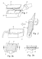
- Figure 1 is shown schematically, as in the state the technology, the sealing compound 1 in the form of a sealing bead on the contour 4 of the housing part or the protective hood 5 an electronic high-frequency circuit 6 applied becomes.
- the sealant 1 is with the help of a Robot 9, which the contour 4 of the hood 5 under output the sealing compound 1 leaves, on the edge, that is Contour 4 of the hood 5, applied. So depending on different contour, shape and size of the hood 5 of the Robot 9 can be programmed accordingly, for moving off the respective contour for an industrial application of the Sealant 1. This procedure is relative time consuming and costly.
- FIGS. 2, 3a and 3b Two exemplary embodiments are shown in FIGS. 2, 3a and 3b the invention is shown schematically.
- the exemplary embodiment according to FIG. 2 is a roller-like one Tool 3 is provided, which has a cylindrical surface B, which is wetted with sealant 1.
- the procedure according to the Invention is fast and the cost of manufacturing Seals for electronic circuits reduced, resulting in lower overall manufacturing costs leads.
- the sealing compound 1 can in particular be a Be plastic mass that is electrically conductive. This is in high-frequency circuits, such as radar sensors or electronic circuits from Mobile phones, required to protect against provide electromagnetic interference to the circuit.
- FIGS. 3a and 3b schematically show a second one Embodiment of the invention shown.
- Figure 3a in a schematic oblique top view a stamp-like Tool 3 reproduced with a flat surface A, with a sealing compound 1 is wetted.
- the area A is in dimensioned to be larger than that External dimensions of the contours 4 of the hoods 5 to be wetted is.
- the Wetting the contour 4 with the sealing compound 1 through the Tool 3 can be the same as in the previous one Embodiment of Figure 2 either by moving the Tool 3 or alternatively by moving the hood 5 with the contour 4 on the respective surface A, B out.
- Figure 3b is the tool 3 of Figure 3a in one Sectional view shown.
- the area A is in a ratio to the upper edge or the "stamp surface" of the tool 3 deepened so that a trough-like depression 8 is formed is.
- the sealant 1 is in the recess 8, for Example by wetting, applied before the surface A of the tool 3 with the contour 4 of the hood 5 is brought together.
- the area A can also be provided on the tool 3 without a recess 8.
Landscapes
- Engineering & Computer Science (AREA)
- Microelectronics & Electronic Packaging (AREA)
- Application Of Or Painting With Fluid Materials (AREA)
Abstract
Description
Claims (9)
- Verfahren zum Aufbringen einer Dichtungsmasse (1) auf eine Kontur (4) eines abzudichtenden Gehäuseteils, insbesondere zur Abdichtung einer Haube (5) einer elektronischen Hochfrequenzschaltung (6), gekennzeichnet durcha). Benetzen einer Fläche (A, B) eines Werkzeuges (3) mit einer Dichtungsmasse (1); undb). Zusammenbringen der benetzten Fläche (A, B) mit der Kontur (4) des Gehäuseteils (5) in einem einzigen Arbeitsgang unabhängig von der Form der Kontur (4).
- Verfahren nach Anspruch 1, gekennzeichnet durch Benetzen einer ebenen Fläche (A) eines stempelartigen Werkzeuges (3) mit Dichtungsmasse (1).
- Verfahren nach Anspruch 1, gekennzeichnet durch Benetzen einer zylinderförmigen Fläche (B) eines walzenartigen Werkzeuges (3) mit Dichtungsmasse (1).
- Verfahren nach einem der vorherigen Ansprüche, gekennzeichnet durch Bewegen der Kontur (4) im Verhältnis zum Werkzeug (3) beim Aufbringen der Dichtungsmasse (1).
- Verfahren nach einem der Ansprüche 1 bis 3, gekennzeichnet durch Bewegen des Werkzeuges (3) im Verhältnis zur Kontur (4) beim Aufbringen der Dichtungsmasse (1).
- Verfahren nach einem der vorherigen Ansprüche, gekennzeichnet durch Abdichten der Kontur einer Haube zur Abschirmung gegen elektromagnetische Störungen mit einer elektrisch leitfähigen Dichtmasse (1) zur Herstellung einer elektronischen Hochfrequenzschaltung.
- Verfahren nach Anspruch 2, gekennzeichnet durch Verwenden eines stempelartiges Werkzeugs (3) mit einer im Verhältnis zur Stempelfläche wannenartig vertieften Fläche (A) zur Aufnahme der Dichtungsmasse (1) beim Benetzen des Werkzeuges (3).
- Verfahren nach einem der vorherigen Ansprüche, gekennzeichnet durch Verwenden eines Werkzeuges (3), welches eine Fläche (A, B) in einer Größe aufweist, die größer ist als die Umhüllende einer maximal zu benetzenden Kontur (4) eines Gehäuseteils (5).
- Vorrichtung zur Durchführung des Verfahrens nach einem der vorhergehenden Ansprüche.
Applications Claiming Priority (2)
| Application Number | Priority Date | Filing Date | Title |
|---|---|---|---|
| DE2002129511 DE10229511A1 (de) | 2002-07-02 | 2002-07-02 | Verfahren zum Aufbringen einer Dichtungsmasse auf eine Kontur eines Gehäuses und Vorrichtung |
| DE10229511 | 2002-07-02 |
Publications (1)
| Publication Number | Publication Date |
|---|---|
| EP1379114A1 true EP1379114A1 (de) | 2004-01-07 |
Family
ID=29719428
Family Applications (1)
| Application Number | Title | Priority Date | Filing Date |
|---|---|---|---|
| EP03010975A Withdrawn EP1379114A1 (de) | 2002-07-02 | 2003-05-16 | Verfahren zum Aufbringen einer Dichtungsmasse auf eine Kontur eines Gehäuses und Vorrichtung |
Country Status (2)
| Country | Link |
|---|---|
| EP (1) | EP1379114A1 (de) |
| DE (1) | DE10229511A1 (de) |
Cited By (1)
| Publication number | Priority date | Publication date | Assignee | Title |
|---|---|---|---|---|
| WO2008083786A1 (de) * | 2006-12-22 | 2008-07-17 | Vatron Gmbh | Verfahren und vorrichtung zum lackieren von schnittflächen |
Families Citing this family (1)
| Publication number | Priority date | Publication date | Assignee | Title |
|---|---|---|---|---|
| DE102013226930B4 (de) * | 2013-12-20 | 2018-01-04 | Continental Automotive Gmbh | Keilförmige Abdeckplatte mit Vertiefung für ein Stützwerkzeug und Verfahren zum Aufbringen einer Dichtungslippe auf eine Abdeckplatte |
Citations (4)
| Publication number | Priority date | Publication date | Assignee | Title |
|---|---|---|---|---|
| GB500474A (en) * | 1936-10-17 | 1939-02-06 | Sealcones Ltd | Improvements in or relating to methods and means for applying an adhesive material to surfaces |
| EP0162011A2 (de) * | 1984-05-08 | 1985-11-21 | Siegfried Frei | Auftragsrolle |
| US4790259A (en) * | 1988-02-29 | 1988-12-13 | Genesis Systems Group, Ltd. | Tool for robotic application of liquid to a work surface |
| US5242497A (en) * | 1991-10-29 | 1993-09-07 | Sweetheart Cup Company Inc. | Applicator systems for applying a localized amount of coating material to top edges of containers |
Family Cites Families (4)
| Publication number | Priority date | Publication date | Assignee | Title |
|---|---|---|---|---|
| US5910524A (en) * | 1995-01-20 | 1999-06-08 | Parker-Hannifin Corporation | Corrosion-resistant, form-in-place EMI shielding gasket |
| DE19516708B4 (de) * | 1995-05-06 | 2007-07-05 | Robert Bosch Gmbh | Flexible Dichtung und ein Verfahren zu deren Herstellung |
| DE19851166C2 (de) * | 1998-11-06 | 2000-11-30 | Hermann Otto Gmbh | Verschäumbare, elektrisch- und wärmeleitfähige Dicht- und Klebstoffe, Verfahren zur Herstellung und ihre Verwendung |
| DE19961187C1 (de) * | 1999-12-18 | 2001-02-08 | Siegfried Schaal Metallveredel | Verfahren zum Herstellen und Aufbringen eines Abschirmprofils |
-
2002
- 2002-07-02 DE DE2002129511 patent/DE10229511A1/de not_active Withdrawn
-
2003
- 2003-05-16 EP EP03010975A patent/EP1379114A1/de not_active Withdrawn
Patent Citations (4)
| Publication number | Priority date | Publication date | Assignee | Title |
|---|---|---|---|---|
| GB500474A (en) * | 1936-10-17 | 1939-02-06 | Sealcones Ltd | Improvements in or relating to methods and means for applying an adhesive material to surfaces |
| EP0162011A2 (de) * | 1984-05-08 | 1985-11-21 | Siegfried Frei | Auftragsrolle |
| US4790259A (en) * | 1988-02-29 | 1988-12-13 | Genesis Systems Group, Ltd. | Tool for robotic application of liquid to a work surface |
| US5242497A (en) * | 1991-10-29 | 1993-09-07 | Sweetheart Cup Company Inc. | Applicator systems for applying a localized amount of coating material to top edges of containers |
Cited By (1)
| Publication number | Priority date | Publication date | Assignee | Title |
|---|---|---|---|---|
| WO2008083786A1 (de) * | 2006-12-22 | 2008-07-17 | Vatron Gmbh | Verfahren und vorrichtung zum lackieren von schnittflächen |
Also Published As
| Publication number | Publication date |
|---|---|
| DE10229511A1 (de) | 2004-01-15 |
Similar Documents
| Publication | Publication Date | Title |
|---|---|---|
| DE2054804C3 (de) | Dichtung, bestehend aus einer Trägerplatte mit Auflagestreifen | |
| WO1999016150A1 (de) | Elektrische kontakteinrichtung sowie verfahren zur schneidkontaktherstellung | |
| DE9404291U1 (de) | Gehäuse, das seinen Innenraum gegenüber elektromagnetischer Strahlung abschirmt | |
| DE19715536A1 (de) | Griffgehäuse mit eingebautem Schalter und Verfahren zu dessen Herstellung | |
| WO2013167570A1 (de) | Steckverbinder, steuergerät und verfahren zur herstellung eines steuergeräts | |
| DE2129918B2 (de) | Schutzvorrichtung fuer elektrische bauteile | |
| DE69936317T2 (de) | Kompressionsstempel | |
| EP2421343A1 (de) | Anlage und Verfahren zum Bearbeiten von Leiterplatten | |
| DE3941917C2 (de) | ||
| DE10229511A1 (de) | Verfahren zum Aufbringen einer Dichtungsmasse auf eine Kontur eines Gehäuses und Vorrichtung | |
| DE102013226930B4 (de) | Keilförmige Abdeckplatte mit Vertiefung für ein Stützwerkzeug und Verfahren zum Aufbringen einer Dichtungslippe auf eine Abdeckplatte | |
| EP0820218B1 (de) | Elektronisches Gerät sowie Abschirmformteil für ein elektronisches Gerät | |
| EP1640938A1 (de) | Verfahren und Vorrichtung zum Stanzen und Prägen von Faltschachtelzuschnitten | |
| CH657475A5 (de) | Elektromagnetisches relais. | |
| DE10026187B4 (de) | Verfahren und eine Vorrichtung zum Aufbringen einer Paste auf einen Bauelementkörper eines elektronischen Bauelements | |
| EP1298976B1 (de) | Verfahren zur Herstellung einer elektromagnetischen Abschirmung | |
| DE10100421A1 (de) | Abgedichtetes Gehäuse für eine elektronische Vorrichtung und zugehörige Dichtung | |
| DE2534192A1 (de) | Tiefdruckzylinder | |
| EP0696881A1 (de) | Kunststoffgehäuse für ein elektrisches Modul | |
| DE2138563C3 (de) | Verfahren zur Herstellung eines piezokeramischen Schwingers, insbesondere für telefonhörer, und piezokeramischer Schwinger gemäß dem Verfahren | |
| DE10120117A1 (de) | Rakelsystem zum Aufbringen eines druckbaren Materials auf eine Oberfläche | |
| DE10254524B4 (de) | Verfahren zur Herstellung eines Halters mit einer Planarantenne sowie Halter für eine Planarantenne | |
| DE2717348A1 (de) | Elektromechanisches bauelement | |
| DE10115091A1 (de) | Verfahren und Vorrichtung zum Aufbringen von Trägerprofilen für Gummidichtungen an Automobilkarosserieteilen | |
| DE102012112736A1 (de) | Anordnung und Verfahren zum Aufbringen von Kunststoff |
Legal Events
| Date | Code | Title | Description |
|---|---|---|---|
| PUAI | Public reference made under article 153(3) epc to a published international application that has entered the european phase |
Free format text: ORIGINAL CODE: 0009012 |
|
| AK | Designated contracting states |
Kind code of ref document: A1 Designated state(s): AT BE BG CH CY CZ DE DK EE ES FI FR GB GR HU IE IT LI LU MC NL PT RO SE SI SK TR |
|
| AX | Request for extension of the european patent |
Extension state: AL LT LV MK |
|
| RIN1 | Information on inventor provided before grant (corrected) |
Inventor name: PAPZINER, UWE Inventor name: KUENZLER, FRANK Inventor name: WALZ, DIRK Inventor name: BIEHLMANN, BERND |
|
| 17P | Request for examination filed |
Effective date: 20040515 |
|
| AKX | Designation fees paid |
Designated state(s): DE FR GB |
|
| RIN1 | Information on inventor provided before grant (corrected) |
Inventor name: PAPZINER, UWE Inventor name: KUENZLER, FRANK Inventor name: WALZ, DIRK Inventor name: BIEHLMANN, BERND |
|
| 17Q | First examination report despatched |
Effective date: 20090721 |
|
| STAA | Information on the status of an ep patent application or granted ep patent |
Free format text: STATUS: THE APPLICATION IS DEEMED TO BE WITHDRAWN |
|
| 18D | Application deemed to be withdrawn |
Effective date: 20091201 |