EP1375868B1 - Dispositif à frein moteur pour un moteur à combustion interne à suralimentation par turbosoufflante - Google Patents
Dispositif à frein moteur pour un moteur à combustion interne à suralimentation par turbosoufflante Download PDFInfo
- Publication number
- EP1375868B1 EP1375868B1 EP02014242A EP02014242A EP1375868B1 EP 1375868 B1 EP1375868 B1 EP 1375868B1 EP 02014242 A EP02014242 A EP 02014242A EP 02014242 A EP02014242 A EP 02014242A EP 1375868 B1 EP1375868 B1 EP 1375868B1
- Authority
- EP
- European Patent Office
- Prior art keywords
- pressure
- exhaust
- turbine
- engine
- braking device
- Prior art date
- Legal status (The legal status is an assumption and is not a legal conclusion. Google has not performed a legal analysis and makes no representation as to the accuracy of the status listed.)
- Expired - Lifetime
Links
Images
Classifications
-
- F—MECHANICAL ENGINEERING; LIGHTING; HEATING; WEAPONS; BLASTING
- F01—MACHINES OR ENGINES IN GENERAL; ENGINE PLANTS IN GENERAL; STEAM ENGINES
- F01N—GAS-FLOW SILENCERS OR EXHAUST APPARATUS FOR MACHINES OR ENGINES IN GENERAL; GAS-FLOW SILENCERS OR EXHAUST APPARATUS FOR INTERNAL-COMBUSTION ENGINES
- F01N13/00—Exhaust or silencing apparatus characterised by constructional features
- F01N13/08—Other arrangements or adaptations of exhaust conduits
- F01N13/10—Other arrangements or adaptations of exhaust conduits of exhaust manifolds
- F01N13/107—More than one exhaust manifold or exhaust collector
-
- F—MECHANICAL ENGINEERING; LIGHTING; HEATING; WEAPONS; BLASTING
- F02—COMBUSTION ENGINES; HOT-GAS OR COMBUSTION-PRODUCT ENGINE PLANTS
- F02B—INTERNAL-COMBUSTION PISTON ENGINES; COMBUSTION ENGINES IN GENERAL
- F02B29/00—Engines characterised by provision for charging or scavenging not provided for in groups F02B25/00, F02B27/00 or F02B33/00 - F02B39/00; Details thereof
- F02B29/04—Cooling of air intake supply
- F02B29/0406—Layout of the intake air cooling or coolant circuit
- F02B29/0412—Multiple heat exchangers arranged in parallel or in series
-
- F—MECHANICAL ENGINEERING; LIGHTING; HEATING; WEAPONS; BLASTING
- F02—COMBUSTION ENGINES; HOT-GAS OR COMBUSTION-PRODUCT ENGINE PLANTS
- F02B—INTERNAL-COMBUSTION PISTON ENGINES; COMBUSTION ENGINES IN GENERAL
- F02B37/00—Engines characterised by provision of pumps driven at least for part of the time by exhaust
- F02B37/004—Engines characterised by provision of pumps driven at least for part of the time by exhaust with exhaust drives arranged in series
-
- F—MECHANICAL ENGINEERING; LIGHTING; HEATING; WEAPONS; BLASTING
- F02—COMBUSTION ENGINES; HOT-GAS OR COMBUSTION-PRODUCT ENGINE PLANTS
- F02B—INTERNAL-COMBUSTION PISTON ENGINES; COMBUSTION ENGINES IN GENERAL
- F02B37/00—Engines characterised by provision of pumps driven at least for part of the time by exhaust
- F02B37/013—Engines characterised by provision of pumps driven at least for part of the time by exhaust with exhaust-driven pumps arranged in series
-
- F—MECHANICAL ENGINEERING; LIGHTING; HEATING; WEAPONS; BLASTING
- F02—COMBUSTION ENGINES; HOT-GAS OR COMBUSTION-PRODUCT ENGINE PLANTS
- F02B—INTERNAL-COMBUSTION PISTON ENGINES; COMBUSTION ENGINES IN GENERAL
- F02B37/00—Engines characterised by provision of pumps driven at least for part of the time by exhaust
- F02B37/02—Gas passages between engine outlet and pump drive, e.g. reservoirs
- F02B37/025—Multiple scrolls or multiple gas passages guiding the gas to the pump drive
-
- F—MECHANICAL ENGINEERING; LIGHTING; HEATING; WEAPONS; BLASTING
- F02—COMBUSTION ENGINES; HOT-GAS OR COMBUSTION-PRODUCT ENGINE PLANTS
- F02B—INTERNAL-COMBUSTION PISTON ENGINES; COMBUSTION ENGINES IN GENERAL
- F02B37/00—Engines characterised by provision of pumps driven at least for part of the time by exhaust
- F02B37/12—Control of the pumps
- F02B37/18—Control of the pumps by bypassing exhaust from the inlet to the outlet of turbine or to the atmosphere
-
- F—MECHANICAL ENGINEERING; LIGHTING; HEATING; WEAPONS; BLASTING
- F02—COMBUSTION ENGINES; HOT-GAS OR COMBUSTION-PRODUCT ENGINE PLANTS
- F02B—INTERNAL-COMBUSTION PISTON ENGINES; COMBUSTION ENGINES IN GENERAL
- F02B37/00—Engines characterised by provision of pumps driven at least for part of the time by exhaust
- F02B37/12—Control of the pumps
- F02B37/22—Control of the pumps by varying cross-section of exhaust passages or air passages, e.g. by throttling turbine inlets or outlets or by varying effective number of guide conduits
-
- F—MECHANICAL ENGINEERING; LIGHTING; HEATING; WEAPONS; BLASTING
- F02—COMBUSTION ENGINES; HOT-GAS OR COMBUSTION-PRODUCT ENGINE PLANTS
- F02B—INTERNAL-COMBUSTION PISTON ENGINES; COMBUSTION ENGINES IN GENERAL
- F02B37/00—Engines characterised by provision of pumps driven at least for part of the time by exhaust
- F02B37/12—Control of the pumps
- F02B37/24—Control of the pumps by using pumps or turbines with adjustable guide vanes
-
- F—MECHANICAL ENGINEERING; LIGHTING; HEATING; WEAPONS; BLASTING
- F02—COMBUSTION ENGINES; HOT-GAS OR COMBUSTION-PRODUCT ENGINE PLANTS
- F02D—CONTROLLING COMBUSTION ENGINES
- F02D23/00—Controlling engines characterised by their being supercharged
- F02D23/02—Controlling engines characterised by their being supercharged the engines being of fuel-injection type
-
- F—MECHANICAL ENGINEERING; LIGHTING; HEATING; WEAPONS; BLASTING
- F02—COMBUSTION ENGINES; HOT-GAS OR COMBUSTION-PRODUCT ENGINE PLANTS
- F02D—CONTROLLING COMBUSTION ENGINES
- F02D9/00—Controlling engines by throttling air or fuel-and-air induction conduits or exhaust conduits
- F02D9/04—Controlling engines by throttling air or fuel-and-air induction conduits or exhaust conduits concerning exhaust conduits
- F02D9/06—Exhaust brakes
-
- F—MECHANICAL ENGINEERING; LIGHTING; HEATING; WEAPONS; BLASTING
- F02—COMBUSTION ENGINES; HOT-GAS OR COMBUSTION-PRODUCT ENGINE PLANTS
- F02M—SUPPLYING COMBUSTION ENGINES IN GENERAL WITH COMBUSTIBLE MIXTURES OR CONSTITUENTS THEREOF
- F02M26/00—Engine-pertinent apparatus for adding exhaust gases to combustion-air, main fuel or fuel-air mixture, e.g. by exhaust gas recirculation [EGR] systems
- F02M26/02—EGR systems specially adapted for supercharged engines
- F02M26/08—EGR systems specially adapted for supercharged engines for engines having two or more intake charge compressors or exhaust gas turbines, e.g. a turbocharger combined with an additional compressor
-
- F—MECHANICAL ENGINEERING; LIGHTING; HEATING; WEAPONS; BLASTING
- F01—MACHINES OR ENGINES IN GENERAL; ENGINE PLANTS IN GENERAL; STEAM ENGINES
- F01N—GAS-FLOW SILENCERS OR EXHAUST APPARATUS FOR MACHINES OR ENGINES IN GENERAL; GAS-FLOW SILENCERS OR EXHAUST APPARATUS FOR INTERNAL-COMBUSTION ENGINES
- F01N2260/00—Exhaust treating devices having provisions not otherwise provided for
- F01N2260/14—Exhaust treating devices having provisions not otherwise provided for for modifying or adapting flow area or back-pressure
-
- F—MECHANICAL ENGINEERING; LIGHTING; HEATING; WEAPONS; BLASTING
- F02—COMBUSTION ENGINES; HOT-GAS OR COMBUSTION-PRODUCT ENGINE PLANTS
- F02B—INTERNAL-COMBUSTION PISTON ENGINES; COMBUSTION ENGINES IN GENERAL
- F02B3/00—Engines characterised by air compression and subsequent fuel addition
- F02B3/06—Engines characterised by air compression and subsequent fuel addition with compression ignition
-
- Y—GENERAL TAGGING OF NEW TECHNOLOGICAL DEVELOPMENTS; GENERAL TAGGING OF CROSS-SECTIONAL TECHNOLOGIES SPANNING OVER SEVERAL SECTIONS OF THE IPC; TECHNICAL SUBJECTS COVERED BY FORMER USPC CROSS-REFERENCE ART COLLECTIONS [XRACs] AND DIGESTS
- Y02—TECHNOLOGIES OR APPLICATIONS FOR MITIGATION OR ADAPTATION AGAINST CLIMATE CHANGE
- Y02T—CLIMATE CHANGE MITIGATION TECHNOLOGIES RELATED TO TRANSPORTATION
- Y02T10/00—Road transport of goods or passengers
- Y02T10/10—Internal combustion engine [ICE] based vehicles
- Y02T10/12—Improving ICE efficiencies
Definitions
- the invention relates to an engine brake device for a turbo-charged internal combustion engine according to the preamble of claim 1, a method according to the preamble of claim 18 for operating the engine brake device and an internal combustion engine having such an engine brake device.
- auxiliary braking device In the field of turbocharged internal combustion engines, it is known that in addition to the engine brake of the internal combustion engine and the turbocharger is provided with its own auxiliary brake device. In a typical operation, such an auxiliary braking device always provides for converting the turbocharger from a power device to a braking device when an auxiliary braking operation is required. This is generally done by modifying the exhaust and / or intake timing of the turbocharger in such a way that movement of the cylinder pistons is converted from the lowest possible power loss to the greatest possible power loss when the turbocharger is decelerating. Such power absorption applies the principle of an air compressor, i. the cylinder pistons exert work on the air trapped in the cylinders of the engine when braking is required.
- an auxiliary brake device for a supercharged internal combustion engine which is provided with an exhaust gas turbine with a variably adjustable via an adjustable guide grille turbine geometry.
- the guide grid includes vanes that can be adjusted by means of an actuator so that the effective, ie effective turbine section of the turbine is changed. In this way, depending on the operating state of the internal combustion engine different high exhaust back pressures can be realized in a section between the cylinders and the turbocharger, whereby the performance of the turbine and the power of the compressor can be adjusted according to need.
- this guide grid is brought into a stowed position such that the effective turbine cross section is significantly reduced.
- a high exhaust back pressure builds up, with the result that exhaust gas flows at high speed through the channels between the guide vanes of the turbine and impart a high impulse to the turbine wheel.
- the turbine power is transferred to the compressor, whereupon the charge air supplied to the engine from the compressor is placed under increased boost pressure.
- the cylinder charge air side is charged with increased boost pressure, abgasplast is between the cylinder outlet and the turbocharger an increased exhaust back pressure, which counteracts a discharge of the compressed air in the cylinder via open brake valves into the exhaust system.
- the piston In engine braking operation, the piston must perform compression work against the high pressure in the exhaust pipe, which, depending on the position of the Leitgitter a more or less strong braking effect is achieved.
- a flap may also be provided which is arranged in the exhaust pipe downstream of the turbine.
- This flap can be pivoted transversely or largely transversely in the exhaust pipe in a braking operation of the engine brake device and thus reduces the effective cross-section in the exhaust pipe, which increases upstream in the direction of the cylinder outlets, the pressure in the exhaust pipe and thus a braking effect is achieved.
- a turbocharger with such a flap is z. B. in the DE 40 24 572 described.
- an exhaust gas recirculation can be provided to increase the engine braking power, which is activated in engine braking operation.
- exhaust gas from the exhaust pipe which usually has unburned combustion air during an engine braking operation and which has an elevated temperature level due to the compression in the cylinders, is returned to the cylinders of the internal combustion engine.
- a method for operating an engine brake device for a turbo-charged internal combustion engine is also known from DE 199 31 009 A1 known.
- an internal combustion engine with such a two-stage charging system is for example in the German Offenlegungsschriften DE 198 37 978 A1 and DE 195 14 572 A1 described.
- the turbocharger group each has a series-arranged high pressure stage and low pressure stage. The exhaust gas from the engine flows through the high-pressure turbine and then the low-pressure turbine.
- the charge air provided for charging the cylinders is first compressed by a low-pressure compressor and then by a high-pressure compressor and, if appropriate, supplied after cooling of the charge air in a heat exchanger of the charge air side of the internal combustion engine.
- the turbocharger is operated in two stages at lower engine speed ranges.
- the high-pressure turbine With increasing speed can be switched to single-stage compression only the low-pressure compressor, for example, by means of exhaust-side bypass lines, the high-pressure turbine is completely or at least partially bridged. It makes sense, in this case, the high-pressure compressor completely bypassed via a charge air side provided pipe switch.
- Another internal combustion engine according to claim 1, the first part, with two-stage charging system is from the JP 01 182533 A known.
- the present invention is therefore based on the object to provide an improved braking device of a two-stage turbocharger of an internal combustion engine.
- this object is achieved by a braking device having the features of patent claim 1. Furthermore, this object is achieved by a method for operating the braking device having the features of patent claim 18 and an internal combustion engine having the features of patent claim 24.
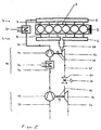
- FIG. 1 illustrates the principle of a two-stage internal combustion engine
- Figures 2 and 6 show embodiments of the invention.
- FIGS. 3 to 5 schematically illustrate design variants of internal combustion engines which can be advantageously integrated in the embodiments of the invention shown in FIGS. 2 and 6. Together with these they form further developments of the invention.
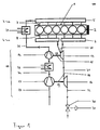
- Figure 1 shows a schematic representation of the principle of a braking device.
- reference numeral 1 denotes an internal combustion engine.
- the internal combustion engine 1 is designed as a six-cylinder diesel internal combustion engine in a row construction and thus has six cylinders 2 arranged in series with one another.
- the internal combustion engine 1 has a fresh air side 3 and an exhaust gas side 4, wherein the inlets 7 are connected on the fresh air side 3 with a charge air manifold 5 and the outlets 8 of the internal combustion engine 1 on the exhaust side 4 with two exhaust manifolds 6.
- the internal combustion engine 1 is charged via a designated with reference numeral 10 turbocharger.
- the turbocharger 10 is exemplified in two stages.
- Such a two-stage turbocharger 10 has a high-pressure stage 11 and a low-pressure stage 12.
- the high pressure stage 11 consists of a high pressure turbine 13 and a high pressure compressor 14, which are rigidly coupled together via a common shaft 15.
- the low-pressure stage 12 accordingly consists of one Low-pressure turbine 16 and a low-pressure compressor 17, which are also coupled together via a common shaft 18.
- the high-pressure stage 11 is connected upstream of the low-pressure stage 12.
- the turbine wheel diameter of the low-pressure turbine 16 is exemplarily larger than that of the high-pressure turbine 13, with the impeller diameter ratio between the low-pressure turbine and the high-pressure turbine typically, but not necessarily, in the range 1.2-1.8.
- the compressor wheel of the high-pressure compressor 14 has a smaller diameter than the compressor wheel of the low-pressure compressor 17.
- the exhaust manifold 6 is connected upstream with exhaust pipes 20, 21, 22, via which the exhaust gas from the cylinders 2 of the internal combustion engine 1 can be derived.
- charge air lines 23, 24, 25 are provided, which are connected upstream with the charge air manifold 5.
- the charge air lines 23, 24, 25 and the compressor 14, 17 is the cylinders 2 of the internal combustion engine 1 charge air supplied.
- the two turbines 13, 16 are arranged in series with each other, wherein the high-pressure turbine 13 is connected to the low-pressure turbine 16 via the exhaust pipe 21 and the low-pressure turbine 16 is arranged upstream in the flow direction of the exhaust gas.
- the low-pressure compressor 17 and the high-pressure compressor 14 are arranged in series with each other and connected to each other via a charge air line 24, wherein the low-pressure compressor 17 upstream of the high-pressure compressor 14 is arranged in the flow direction of the charge air.
- first intercooler 26 is provided, which is arranged in the charge air line 24 between the two compressors 14, 17.
- a second charge air cooler 27 is in La deluft admir 25 arranged between the high-pressure compressor 14 and inlets 7 of the internal combustion engine 1. If necessary, can be dispensed with one or in an extreme case, both intercoolers 26, 27.
- a variable closure device 30 is provided, which is designed here as a controllable or controllable valve.
- the closure device 30 may also be designed as a brake flap, throttle valve, slider or the like.
- the valve 30 is adjustable.
- the closure device 30 may be designed to be controllable or controllable via a regulating or control device (not shown in FIG. 1). The function of such a control device or control device will be described in more detail below with reference to FIG.
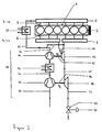
- the arrangement according to FIG. 2 has an exhaust gas recirculation line 32 according to the invention.
- the exhaust gas recirculation line 32 branches off from the exhaust gas lines 20 coming out of the exhaust manifolds 6 and branches into the charge air line 25 which connects the high-pressure compressor 14 to the charge air manifold 5.
- the particular advantage of the arrangement shown in Figure 2 is that due to the pressure conditions in the exhaust pipes 6, 20 and the charge air lines 5, 25 no check valve is provided and beyond, as will be explained below, is not required.
- turbo-charged internal combustion engine 1 has a turbocharger 10 which has a high-pressure turbine 13 with variable turbine geometry (VTG).
- VFG variable turbine geometry
- the functionality of a variable turbine geometry is indicated in all figures with an arrow.
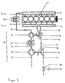
- the turbo-charged internal combustion engine according to FIG. 4 has a high-pressure turbine 13 in the form of a twin-flow turbine.
- This twin-flow high-pressure turbine 13 consists of two mutually parallel turbine wheels 13A, 13B, which are coupled together, typically rigidly. Typically, though not necessarily, these two turbine wheels 13A, 13B have the same flow area of the turbine ducts.
- the closure device 30 is arranged between the high-pressure stage and the low-pressure stage 11, 12. Since the brake flap 30 acts directly on the high-pressure stage here, this arrangement is distinguished from the arrangement in FIG. 1 in that higher accuracy and rapidity of the regulation of the high-pressure stage 11 are possible.
- a bypass line is advantageously provided in each case symmetrical circuit per channel 13A, 13B of the twin-flow twin-pressure turbine 13.
- Each bypass line 33A, 33B is provided with a downstream of the branch pipe switch 34A, 34B, which may be formed, for example, as a control valve provided.
- tube switches 34A, 34B are advantageously integrated in the exhaust manifold or in the housing of the high-pressure turbine 13 and can be designed as a slide, valve, flap, throttle or the like, and e.g. be controlled via a program-controlled unit, such as a CPU, either individually or jointly.
- the turbine wheels 13A, 13B of the twin-flow high-pressure turbine 13 become operated synchronously.
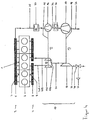
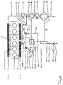
- FIG. 6 shows a schematic representation of a particularly preferred embodiment of a two-stage supercharged internal combustion engine according to the invention.
- the preferred arrangement in Figure 6 consists essentially of a combination of the different embodiments of an internal combustion engine 1 according to Figures 1-4.
- the internal combustion engine 1 is here with a control valve 30, an exhaust gas recirculation line 32, bypass lines 33A, 33B with therein pipe switches 34A, 34B fitted.
- the high-pressure stage 11 has a twin-flow high-pressure turbine 13, in which the high-pressure turbines 13A, 13B each have a variable turbine geometry.
- the low-pressure turbine 12 can of course also be designed as a twin-flow turbine.
- the low-pressure turbine 12 may also have a variable turbine geometry.
- FIG. 6 additionally shows a control device 40.
- the control device 40 has data inputs 41 and data outputs 42.
- analog measured variables for example the temperature or the pressure of the exhaust gas or the charge air, the number of revolutions of the engine, etc., or digital data can be coupled in via the data inputs 41.
- Dependent on these data and generated by a predetermined program of the control device 40 These control signals, which can be tapped off at the outputs 42 of the control device 40.
- the data outputs 42 are connected via a plurality of control lines 43-46 to the control valves 34A, 34B, to the twin-flow pressure turbine 13, to the low-pressure turbine 12 and to the actuator 31 of the control valve 30.
- a throttle 35 is provided, which is arranged connected in the exhaust gas recirculation line 32. This is typically likewise set or activated via the control device 40.
- exhaust gas recirculation can be provided, in which a subset of the recirculated exhaust gas is fed to any other point on the charge air side. Typically, but not necessarily, up to about 50% of the exhaust gas of the internal combustion engine 10 is returned to the charge air side 3.
- the six-cylinder diesel engine 1 is charged in two stages via a turbocharger 10.
- a double-flow high pressure stage 11 upstream of a single-flow low-pressure stage 12.
- Charge air is compressed via the compressors 14 and 17 driven by the twin streams 13A, 13B and the low-pressure turbine 16, cooled in the two charge air coolers 26, 27, mixed with exhaust gas from the exhaust gas recirculation line 32 to a certain proportion ( ⁇ 0) and the charge air side 3 the internal combustion engine 1 is supplied.
- an increased engine braking power can be produced, which is made possible by an increased exhaust gas pressure caused by the small high-pressure stage 11.
- the corresponding speed range can be optimally adjusted during braking operation.
- the different channel diameters of the two high-pressure turbines 13A, 13B can be adjusted specifically by suitable control of the engine control unit 40 due to their variable turbine geometry. As a result, a differential distribution of the exhaust gas mass flow to high-pressure and low-pressure stage 11, 12 can be divided.
- a throttle 35 is nevertheless arranged in the exhaust gas recirculation line 32, via which the exhaust gas mass flow can be additionally metered via the exhaust gas recirculation line 32 with suitable control.
- the engine characteristics can be selectively influenced, for example, by setting the engine operating values as far as possible optimally with regard to pollutant emissions (N OX , CO, CO 2 ) and with regard to fuel consumption.
- the particular advantage of this exhaust gas recirculation according to the invention is that the exhaust gas flow is already ensured solely by the pressure gradient between the exhaust gas side and the charge air side. Therefore, it is completely sufficient to provide only a flow restrictor in the exhaust gas recirculation line 32, which - as already mentioned - can also be dispensed with without significant impairment of the function of the auxiliary brake device.
- the invention is not limited exclusively to two-stage turbocharger, but rather can be extended to three- or multi-stage turbocharger.
- the two turbocharger stages are advantageously part of a single turbocharger in the present embodiment and are thus integrated in a housing of this turbocharger.
- this advantageous integration of two turbocharger stages in a turbocharger is not absolutely necessary, but it could be the same function also achieved by two separate, sequentially switched turbocharger, although this arrangement is less technical for assembly and because of the higher cost.
- the invention is not limited exclusively to diesel engines in six-cylinder in-line construction, but can be extended to any engine with any number of any arranged cylinders.
- the low-pressure stage has a larger diameter than the high-pressure stage of the corresponding turbine wheels.
- this is not absolutely necessary, but it is also conceivable that the two turbine stages have the same turbine wheel diameter or the high-pressure stage has the larger wheel diameter.
- closure body valves, flaps, pipe switches, etc.
- turbine geometry was described by the engine control. Of course, some or all of these elements can also be otherwise controlled or adapted by a specially provided control device to the desired operating condition.
- the adjustment of the closure body or the turbine geometry can be done electrically, pneumatically, hydraulically or mechanically.
Landscapes
- Engineering & Computer Science (AREA)
- Chemical & Material Sciences (AREA)
- Combustion & Propulsion (AREA)
- Mechanical Engineering (AREA)
- General Engineering & Computer Science (AREA)
- Physics & Mathematics (AREA)
- Thermal Sciences (AREA)
- Supercharger (AREA)
- Control Of Throttle Valves Provided In The Intake System Or In The Exhaust System (AREA)
- Output Control And Ontrol Of Special Type Engine (AREA)
- Exhaust-Gas Circulating Devices (AREA)
- Control Of Vehicle Engines Or Engines For Specific Uses (AREA)
Claims (26)
- Dispositif de frein moteur pour un moteur à combustion interne (1) turbocompressé,
avec un système de suralimentation (10) réalisé à au moins deux étages, qui présente au moins un étage à haute pression (11) ainsi qu'au moins un étage à basse pression (12) monté en aval de l'étage à haute pression (11) du côté des gaz d'échappement et en amont du côté de l'air de suralimentation,
avec au moins une conduite d'échappement (20, 20A, 20B, 21, 22) reliée aux canaux d'évacuation (8) du moteur à combustion interne (1) et disposée en aval du moteur à combustion interne (1) du côté des gaz d'échappement,
avec au moins un premier obturateur (30) qui est disposé dans une région de la conduite d'échappement (22) montée en aval de l'étage à haute pression (11) du côté des gaz d'échappement, le premier obturateur (30) étant conçu de telle sorte que le flux de gaz d'échappement, et par suite une pression (P1) dans la conduite d'échappement (20, 20A, 20B, 21, 22), peut être modifié(e) de telle sorte que la puissance du frein moteur peut être ainsi réglée de manière variable en fonction des besoins,
caractérisé en qu'il est prévu un dispositif (32, 35) de recyclage des gaz d'échappement qui présente au moins une conduite (32) de recyclage des gaz d'échappement au moyen de laquelle une quantité partielle des gaz d'échappement peut être amenée, d'une conduite d'échappement (20, 20A, 20B) située en amont d'une turbine (13, 13A, 13B) de l'étage à haute pression (11), à une conduite (25) d'air de suralimentation située en aval d'un compresseur (14) de l'étage à haute pression (11). - Dispositif de frein moteur selon la revendication 1, caractérisé en ce que l'obturateur (30) peut être commandé ou réglé.
- Dispositif de frein moteur selon l'une quelconque des revendications précédentes, caractérisé en ce que le premier obturateur (30) est conçu comme soupape de régulation (30) ou comme clapet de frein d'échappement ou comme clapet d'étranglement d'échappement.
- Dispositif de frein moteur selon l'une quelconque des revendications précédentes, caractérisé en ce qu'au moins un premier obturateur (30) est disposé dans une région de la conduite d'échappement (22) montée en aval de l'étage à basse pression (12) du côté des gaz d'échappement.
- Dispositif de frein moteur selon l'une quelconque des revendications précédentes, caractérisé en ce qu'il n'est pas prévu de clapet anti-retour dans la conduite (32) de recyclage des gaz d'échappement, et en ce qu'une première pression (P1) dans la conduite d'échappement (20, 20A, 20B) en amont de la turbine (13, 13A, 13B) est toujours supérieure à une deuxième pression (P2) dans la conduite (25) d'air de suralimentation en aval du compresseur (14).
- Dispositif de frein moteur selon l'une quelconque des revendications précédentes, caractérisé en ce qu'il est prévu un étranglement d'écoulement (35) qui est disposé dans la conduite (32) de recyclage des gaz d'échappement et au moyen duquel est définie la quantité partielle de gaz d'échappement qui sera ramenée dans la conduite (25) d'air de suralimentation via la conduite (32) de recyclage des gaz d'échappement.
- Dispositif de frein moteur selon l'une quelconque des revendications précédentes, caractérisé en ce que le turbocompresseur (10) présente les éléments suivants :- l'étage à haute pression (11) comporte au moins une turbine à haute pression (13, 13A, 13B) disposée du côté des gaz d'échappement et au moins un compresseur à haute pression (14) disposé du côté de l'air de suralimentation, qui sont couplés entre eux via un premier arbre commun (15) disposé entre eux ;- l'étage à basse pression (12) comporte au moins une turbine à basse pression (16) disposée du côté des gaz d'échappement et au moins un compresseur à basse pression (17) disposé du côté de l'air de suralimentation, qui sont couplés entre eux via un deuxième arbre commun (18) disposé entre eux ;- il est prévu au moins un refroidisseur (26, 27) d'air de suralimentation, qui est disposé du côté de l'air de suralimentation entre un compresseur (14, 17) et une admission (7) d'air de suralimentation du moteur à combustion interne (1).
- Dispositif de frein moteur selon l'une quelconque des revendications précédentes, caractérisé en ce qu'au moins une des turbines (13, 16) est conçue comme turbine à géométrie variable.
- Dispositif de frein moteur selon l'une quelconque des revendications précédentes, caractérisé en ce qu'au moins une turbine (13, 13A, 13B) du turbocompresseur (10) est conçue comme turbine à double flux (13A, 13B), où deux roues de turbine (13A, 13B) sont disposées en étant montées en parallèle.
- Dispositif de frein moteur selon la revendication 9, caractérisé en ce que les deux roues de turbine (13A, 13B) de la turbine à double flux (13A, 13B) présentent un canal d'échappement de section d'écoulement différente.
- Dispositif de frein moteur selon l'une quelconque des revendications précédentes, caractérisé en ce qu'une conduite de dérivation respective (33A, 33B), avec un deuxième obturateur respectif (34A, 34B) disposé dans cette conduite, est montée en parallèle avec chaque turbine à haute pression (13, 13A, 13B).
- Dispositif de frein moteur selon l'une quelconque des revendications 9 à 11, caractérisé en ce que les deuxièmes obturateurs (34A, 34B) respectivement disposés dans la conduite de dérivation (33A, 33B) de la conduite à double flux (13) peuvent être commandés ou réglés indépendamment entre eux.
- Dispositif de frein moteur selon l'une quelconque des revendications précédentes, caractérisé en ce qu'au moins un obturateur (30, 34A, 34B) est réalisé sous forme de soupape et/ou d'étranglement et/ou de clapet et/ou de tiroir.
- Dispositif de frein moteur selon l'une quelconque des revendications précédentes, caractérisé en ce qu'il est prévu un dispositif de commande (40) qui fournit un signal de commande ou de réglage par l'intermédiaire duquel le premier obturateur (30) et/ou les deuxièmes obturateurs (34A, 34B) et/ou l'étranglement d'écoulement (35) et/ou les turbines (13, 16) à géométrie variable peuvent être commandés ou réglés.
- Dispositif de frein moteur selon la revendication 14, caractérisé en ce que le dispositif de commande (40) fait partie de la gestion moteur qui présente une unité programmée par programme, notamment un microprocesseur ou microcontrôleur.
- Dispositif de frein moteur selon l'une quelconque des revendications précédentes, caractérisé en ce que le signal de commande ou de réglage est un signal électrique ou pneumatique ou hydraulique.
- Dispositif de frein moteur selon l'une quelconque des revendications précédentes, caractérisé en ce qu'au moins un des obturateurs (30, 34A, 34B) ou l'étranglement d'écoulement (35) est conjointement intégré dans un carter du turbocompresseur (10).
- Procédé d'exploitation d'un dispositif de frein moteur selon l'une quelconque des revendications 1 à 17, selon lequel, au moyen d'un dispositif de commande (40), une première pression (P1) dans une conduite d'échappement (20, 20A, 20B) disposée en amont d'une turbine à haute pression (13) de l'étage à haute pression (11) est réglée à une valeur prédéfinie en fonction d'un mode de freinage,
caractérisé en ce que des gaz d'échappement sont apportés via le dispositif (32, 35) de recyclage des gaz d'échappement à la conduite (25) d'air de suralimentation, et le réglage de la première pression (P1) dans la conduite d'échappement (22) et/ou d'une deuxième pression (P2) dans la conduite (25) d'air de suralimentation en aval du compresseur (14) de l'étage à haute pression (11) s'effectue en agissant sur la section d'écoulement de la conduite d'échappement (22) disposée en aval d'une turbine à basse pression (16) de l'étage à basse pression (12), par le fait que l'obturateur (30) est plus ou moins ouvert selon la section d'écoulement souhaitée. - Procédé selon la revendication 18, caractérisé en ce que la première pression (P1) est réglée, en service de freinage, de telle sorte qu'elle est toujours supérieure à une deuxième pression (P2) dans la conduite (25) d'air de suralimentation disposée en aval du compresseur à haute pression (14).
- Procédé selon la revendication 18 ou 19, caractérisé en ce que la première pression (P1) et/ou la deuxième pression (P2) sont réglées de telle sorte qu'elles sont toujours constantes pendant le service de freinage du turbocompresseur (10).
- Procédé selon l'une quelconque des revendications 18 à 20, caractérisé en ce que le réglage de la première pression (P1) et/ou de la deuxième pression (P2) s'effectue en agissant sur la section d'écoulement d'un canal d'au moins une turbine (13, 13A, 13B, 16), par le fait que les canaux de turbines sont plus ou moins ouverts selon la section d'écoulement souhaitée.
- Procédé selon l'une quelconque des revendications 18 à 21, caractérisé en ce que le réglage de la première pression (P1) et/ou de la deuxième pression (P2) s'effectue en agissant sur la section d'écoulement au moins d'obturateurs supplémentaires (34A, 34B), par le fait que le deuxième obturateur (34A, 34B) est plus ou moins ouvert selon la section d'écoulement souhaitée.
- Moteur à combustion interne (1),
avec un bloc-moteur qui présente au moins un cylindre (2) et qui présente au moins une admission (7) d'air de suralimentation et au moins une évacuation (8) de gaz d'échappement,
avec un système de suralimentation (10) conçu comme dispositif de frein moteur selon l'une quelconque des revendications 1 à 17. - Moteur à combustion interne selon la revendication 23, caractérisé en ce que le système de suralimentation (10) est réalisé sous forme de turbocompresseur (10).
- Moteur à combustion interne selon la revendication 23 ou 24, caractérisé en ce que le moteur à combustion interne (1) est réalisé sous forme de moteur à essence ou de moteur diesel.
- Moteur à combustion interne selon l'une quelconque des revendications 23 à 25, caractérisé en ce qu'il est prévu au moins un premier catalyseur qui est monté du côté des gaz d'échappement en aval du turbocompresseur (10) et en série avec lui.
Priority Applications (5)
| Application Number | Priority Date | Filing Date | Title |
|---|---|---|---|
| EP02014242A EP1375868B1 (fr) | 2002-06-26 | 2002-06-26 | Dispositif à frein moteur pour un moteur à combustion interne à suralimentation par turbosoufflante |
| DE50211459T DE50211459D1 (de) | 2002-06-26 | 2002-06-26 | Motorbremseinrichtung für eine turboaufgeladene Brennkraftmaschine |
| BRPI0301766-4A BR0301766B1 (pt) | 2002-06-26 | 2003-06-23 | dispositivo e processo para operar um dispositivo de frenagem do motor turboalimentado e motor de combustão interna. |
| JP2003177879A JP4656821B2 (ja) | 2002-06-26 | 2003-06-23 | ターボ過給する内燃エンジン用のエンジンブレーキ装置 |
| US10/606,974 US6973787B2 (en) | 2002-06-26 | 2003-06-26 | Motor brake device for a turbocharged internal combustion engine |
Applications Claiming Priority (1)
| Application Number | Priority Date | Filing Date | Title |
|---|---|---|---|
| EP02014242A EP1375868B1 (fr) | 2002-06-26 | 2002-06-26 | Dispositif à frein moteur pour un moteur à combustion interne à suralimentation par turbosoufflante |
Publications (2)
| Publication Number | Publication Date |
|---|---|
| EP1375868A1 EP1375868A1 (fr) | 2004-01-02 |
| EP1375868B1 true EP1375868B1 (fr) | 2008-01-02 |
Family
ID=29716844
Family Applications (1)
| Application Number | Title | Priority Date | Filing Date |
|---|---|---|---|
| EP02014242A Expired - Lifetime EP1375868B1 (fr) | 2002-06-26 | 2002-06-26 | Dispositif à frein moteur pour un moteur à combustion interne à suralimentation par turbosoufflante |
Country Status (5)
| Country | Link |
|---|---|
| US (1) | US6973787B2 (fr) |
| EP (1) | EP1375868B1 (fr) |
| JP (1) | JP4656821B2 (fr) |
| BR (1) | BR0301766B1 (fr) |
| DE (1) | DE50211459D1 (fr) |
Families Citing this family (68)
| Publication number | Priority date | Publication date | Assignee | Title |
|---|---|---|---|---|
| SE525219C2 (sv) * | 2003-05-15 | 2004-12-28 | Volvo Lastvagnar Ab | Turboladdarsystem för en förbränningsmotor där båda kompressorstegen är av radialtyp med kompressorhjul försedda med bakåtsvepta blad |
| DE102004009794A1 (de) | 2004-02-28 | 2005-09-22 | Daimlerchrysler Ag | Brennkraftmaschine mit zwei Abgasturboladern |
| DE102004038172A1 (de) * | 2004-08-06 | 2006-02-23 | Daimlerchrysler Ag | Brennkraftmaschine |
| EP1640595A1 (fr) * | 2004-09-22 | 2006-03-29 | Ford Global Technologies, LLC, A subsidary of Ford Motor Company | Moteur à combustion interne à suralimentation et procédé pour faire fonctionner un tel moteur à combustion interne |
| DE502004007683D1 (de) * | 2004-09-22 | 2008-09-04 | Ford Global Tech Llc | Aufgeladene Brennkraftmaschine und Verfahren zum Betreiben einer derartigen Brennkraftmaschine |
| EP1640596B2 (fr) | 2004-09-22 | 2016-09-07 | Ford Global Technologies, LLC, A subsidary of Ford Motor Company | Moteur à combustion interne à suralimentation et procédé pour faire fonctionnner un tel moteur à combustion interne |
| JP2006097684A (ja) * | 2004-09-27 | 2006-04-13 | Borgwarner Inc | Vtgタービン段を利用する多段ターボ過給装置 |
| DE102004052670A1 (de) * | 2004-10-29 | 2006-05-04 | Daimlerchrysler Ag | Verfahren zum Betrieb einer Brennkraftmaschine im Motorbremsbetrieb |
| DE102004056894A1 (de) * | 2004-11-25 | 2006-06-01 | Robert Bosch Gmbh | Verfahren und Vorrichtung zur Regelung des Ladedrucks einer Brennkraftmaschine |
| US20060137343A1 (en) | 2004-12-14 | 2006-06-29 | Borgwarner Inc. | Turbine flow regulating valve system |
| US20060137342A1 (en) * | 2004-12-14 | 2006-06-29 | Borgwarner Inc. | Turbine flow regulating valve system |
| DE102004062492A1 (de) * | 2004-12-24 | 2006-07-13 | Daimlerchrysler Ag | Verfahren zum Betrieb einer Brennkraftmaschine mit einem Abgasturbolader und einer Nutzturbine |
| DE102005008657A1 (de) * | 2005-02-25 | 2006-08-31 | Daimlerchrysler Ag | Motorbremsverfahren für eine Brennkraftmaschine mit zwei in Reihe geschalteten Abgasturboladern |
| JP4906847B2 (ja) * | 2005-05-11 | 2012-03-28 | ボーグワーナー インコーポレーテッド | エンジンの空気管理装置 |
| DE102005025885B4 (de) * | 2005-06-06 | 2010-04-29 | Audi Ag | Aufladevorrichtung für eine Verbrennungskraftmaschine |
| US7426831B2 (en) * | 2005-10-06 | 2008-09-23 | Borgwarner Inc. | Turbo charging system |
| FR2892155B1 (fr) * | 2005-10-19 | 2007-12-14 | Inst Francais Du Petrole | Circuit d'alimentation en au moins un fluide d'un moteur suralimente et procede pour alimenter en au moins un fluide un tel moteur |
| AT502997B1 (de) * | 2005-12-20 | 2013-09-15 | Man Truck & Bus Oesterreich Ag | Vorrichtung zur steigerung der bremsleistung einer mehrzylindrigen brennkraftmaschine eines fahrzeugs während des motorbremsbetriebes |
| DE102006004725A1 (de) * | 2006-02-02 | 2007-08-09 | Bayerische Motoren Werke Ag | Abgaskrümmer für eine Reihen-Brennkraftmaschine |
| DE102006010247B4 (de) * | 2006-03-02 | 2019-12-19 | Man Truck & Bus Se | Antriebseinheit mit Wärmerückgewinnung |
| US20070204616A1 (en) * | 2006-03-06 | 2007-09-06 | Honeywell International, Inc. | Swing valve for a turbocharger with stacked valve members, and two-stage turbocharger system incorporating same |
| US20080000228A1 (en) * | 2006-06-30 | 2008-01-03 | Caterpillar Inc. | System and method for exhaust recirculation |
| US9103274B2 (en) | 2006-07-29 | 2015-08-11 | Cummins Emission Solution Inc. | Multi-stage turbocharger system |
| EP2087223A1 (fr) | 2006-11-23 | 2009-08-12 | Renault Trucks | Moteur à combustion interne avec système de recirculation des gaz d'échappement |
| US7644584B2 (en) * | 2006-11-30 | 2010-01-12 | Caterpillar Inc. | Method for modulating turbocharger braking |
| DE102007010123A1 (de) * | 2007-02-28 | 2008-09-04 | Behr Gmbh & Co. Kg | Vorrichtung zur Ladeluftkühlung, System zur Turboaufladung und/oder Ladeluftkühlung, Verfahren zur Ladeluftkühlung |
| SE531200C2 (sv) * | 2007-03-15 | 2009-01-13 | Scania Cv Ab | Kylararrangemang i ett fordon |
| DE102007037087A1 (de) * | 2007-08-06 | 2009-02-12 | Robert Bosch Gmbh | Aufladeeinrichtung |
| GB0717212D0 (en) | 2007-09-05 | 2007-10-17 | Cummins Turbo Tech Ltd | Multi-stage turbocharger system |
| US20090178406A1 (en) * | 2008-01-14 | 2009-07-16 | Jeffrey Matthews | Apparatus, system, and method for utilizing a diesel aftertreatment device between the high pressure and low pressure turbine stages of a two-stage turbocharging system |
| US8001783B2 (en) * | 2008-01-24 | 2011-08-23 | Cummins Ip, Inc. | Apparatus, system, and method for turbocharger bypass and exhaust braking with a single valve |
| KR101506696B1 (ko) * | 2008-02-29 | 2015-04-06 | 보르그워너 인코퍼레이티드 | 열 바이패스를 가지는 다단 터보차징 시스템 |
| EP2098708A1 (fr) * | 2008-03-06 | 2009-09-09 | Wärtsilä Schweiz AG | Procédé pour le fonctionnement d'un moteur diesel à deux temps à balayage longitudinal et moteur diesel à deux temps à balayage longitudinal |
| US8214113B2 (en) * | 2008-06-30 | 2012-07-03 | Caterpillar Inc. | Retarding system that retards motion of power source |
| US8161747B2 (en) * | 2008-07-31 | 2012-04-24 | Caterpillar Inc. | Exhaust system having series turbochargers and EGR |
| JP4574700B2 (ja) * | 2008-08-01 | 2010-11-04 | 本田技研工業株式会社 | 過給機制御装置および排気絞り弁制御装置を備える内燃機関 |
| US8448626B2 (en) * | 2008-08-13 | 2013-05-28 | International Engine Intellectual Property Company, Llc | Exhaust system for engine braking |
| US8096124B2 (en) * | 2008-09-30 | 2012-01-17 | Caterpillar Inc. | Exhaust system having parallel asymmetric turbochargers and EGR |
| DE102008052170B4 (de) * | 2008-10-17 | 2023-01-26 | Bayerische Motoren Werke Aktiengesellschaft | Zweistufige Abgasturboaufladung für eine Brennkraftmaschine |
| US8738248B2 (en) * | 2008-10-21 | 2014-05-27 | Allison Transmission, Inc. | System for controlling vehicle overspeeding via control of one or more exhaust brake devices |
| US8234864B2 (en) * | 2008-12-16 | 2012-08-07 | Caterpillar Inc. | Engine system having multi-stage turbocharging and exhaust gas recirculation |
| US20100154412A1 (en) * | 2008-12-23 | 2010-06-24 | Cummins Inc. | Apparatus and method for providing thermal management of a system |
| JP2010180782A (ja) * | 2009-02-05 | 2010-08-19 | Isuzu Motors Ltd | 内燃機関の多段過給システム及びその制御方法 |
| US8966897B2 (en) * | 2009-02-26 | 2015-03-03 | Borgwarner Inc. | Internal combustion engine |
| US8096123B2 (en) * | 2009-05-29 | 2012-01-17 | GM Global Technology Operations LLC | System and method for mode transition for a two-stage series sequential turbocharger |
| US8250866B2 (en) * | 2009-07-30 | 2012-08-28 | Ford Global Technologies, Llc | EGR extraction immediately downstream pre-turbo catalyst |
| GB2472829B (en) * | 2009-08-20 | 2014-04-02 | Gm Global Tech Operations Inc | Two-stage turbocharged engine system |
| GB2475534B (en) | 2009-11-21 | 2014-11-12 | Cummins Turbo Tech Ltd | Sequential two-stage turbocharger system |
| US10054037B2 (en) | 2009-11-21 | 2018-08-21 | Cummins Turbo Technologies Limited | Multi-stage turbocharger system with bypass flowpaths and flow control valve |
| US9995207B2 (en) | 2009-11-21 | 2018-06-12 | Cummins Turbo Technologies Limited | Multi-stage turbocharger system |
| WO2012051784A1 (fr) * | 2010-10-18 | 2012-04-26 | Jin Beibiao | Moteur turbocompound à explosion, à combustion mixte et à faible entropie |
| EP2466092A1 (fr) * | 2010-12-17 | 2012-06-20 | Perkins Engines Company Limited | Système de turbocompresseur |
| DE102011100684A1 (de) * | 2011-05-06 | 2012-11-08 | GM Global Technology Operations LLC (n. d. Gesetzen des Staates Delaware) | Brennkraftmaschine und Kraftfahrzeug |
| CN102748085B (zh) * | 2011-06-17 | 2014-07-16 | 摩尔动力(北京)技术股份有限公司 | 充气爆排发动机直控阀 |
| CN202745945U (zh) * | 2011-06-21 | 2013-02-20 | 摩尔动力(北京)技术股份有限公司 | 小余隙容积爆排发动机 |
| US8783028B2 (en) * | 2011-08-16 | 2014-07-22 | Caterpillar Inc. | EGR performance balancing restrictor for an engine system |
| CN102562265A (zh) * | 2012-01-11 | 2012-07-11 | 清华大学 | 二级涡轮增压系统 |
| US9074521B2 (en) * | 2012-03-21 | 2015-07-07 | Ford Global Technologies, Llc | Turbocharger system having a shared bypass conduit and wastegate |
| US9163586B2 (en) * | 2013-01-31 | 2015-10-20 | Electro-Motive Diesel, Inc. | Exhaust system having parallel EGR coolers |
| US10094324B2 (en) * | 2013-05-30 | 2018-10-09 | General Electric Company | System and method of operating an internal combustion engine |
| DE102014215885B3 (de) * | 2014-08-11 | 2015-12-31 | Ford Global Technologies, Llc | Aufgeladene Brennkraftmaschine mit Mixed-Flow-Turbine |
| US9903268B2 (en) * | 2015-04-02 | 2018-02-27 | Ford Global Technologies, Llc | Internal combustion engine with two-stage supercharging capability and with exhaust-gas aftertreatment arrangement, and method for operating an internal combustion engine |
| FR3059719B1 (fr) * | 2016-12-05 | 2019-08-09 | Renault S.A.S | Procede de commande d'un moteur thermique suralimente comprenant un circuit de recirculation des gaz d'echappement |
| DE102017201732A1 (de) | 2017-02-03 | 2018-08-09 | Ford Global Technologies, Llc | Verfahren zum Betreiben einer Brennkraftmaschine im Schubbetrieb und Brennkraftmaschine zur Durchführung eines derartigen Verfahrens |
| CN108104941B (zh) * | 2017-12-30 | 2020-06-02 | 中国科学院工程热物理研究所 | 一种高空两级涡轮增压器冷却系统及其调控方法 |
| CN108825359B (zh) * | 2018-06-30 | 2023-06-20 | 华南理工大学 | 一种内燃机两级涡轮负荷动态控制装置及方法 |
| US10890129B1 (en) * | 2019-06-18 | 2021-01-12 | Fca Us Llc | High pressure loop exhaust gas recirculation and twin scroll turbocharger flow control |
| US11585301B1 (en) * | 2021-12-14 | 2023-02-21 | Ford Global Technologies, Llc | Two-stage boost system for engines |
Family Cites Families (17)
| Publication number | Priority date | Publication date | Assignee | Title |
|---|---|---|---|---|
| US4096697A (en) * | 1974-06-28 | 1978-06-27 | Societe D'etudes De Machines Thermiques S.E.M.T. | Method and means for conditioning the intake air of a supercharged, low-compression ratio diesel engine |
| US4138849A (en) * | 1977-06-06 | 1979-02-13 | Cummins Engine Company, Inc. | Exhaust braking valve |
| JPS5982526A (ja) * | 1982-10-29 | 1984-05-12 | Hino Motors Ltd | 内燃機関の過給装置 |
| JPH01182533A (ja) * | 1988-01-13 | 1989-07-20 | Hino Motors Ltd | 過給機付エンジンの排気ブレーキ装置 |
| JPH0417714A (ja) * | 1990-05-09 | 1992-01-22 | Toyota Motor Corp | 2段過給内燃機関の排気ガス浄化装置 |
| DE4024572C2 (de) | 1990-08-02 | 1994-11-10 | Kloeckner Humboldt Deutz Ag | Registeraufladung für Brennkraftmaschinen in Nutzfahrzeugen |
| JP3443748B2 (ja) * | 1994-04-04 | 2003-09-08 | 石川島播磨重工業株式会社 | 過給ディーゼルエンジンのegr装置 |
| SE502721C2 (sv) * | 1994-05-13 | 1995-12-18 | Scania Cv Ab | Förbränningsmotor av turbocompoundtyp med avgasbroms |
| DE19514572C2 (de) | 1995-04-20 | 1997-04-30 | Man Nutzfahrzeuge Ag | Aufgeladene Brennkraftmaschine |
| DE19543190C2 (de) | 1995-11-20 | 1998-01-29 | Daimler Benz Ag | Motorbremse für eine aufgeladene Brennkraftmaschine |
| DE19709879A1 (de) * | 1997-03-11 | 1998-09-24 | Man Nutzfahrzeuge Ag | Steuervorrichtung für eine aufgeladene Brennkraftmaschine |
| WO1999054607A1 (fr) * | 1998-04-16 | 1999-10-28 | 3K-Warner Turbosystems Gmbh | Moteur a combustion interne turbocompresse |
| DE19837978B4 (de) | 1998-04-16 | 2006-05-18 | Borgwarner Turbo Systems Gmbh | Turboaufgeladene Brennkraftmaschine |
| DE19853127B4 (de) | 1998-11-18 | 2008-05-15 | Daimler Ag | Motorbremsverfahren und Motorbremseinrichtung für eine aufgeladene Brennkraftmaschine |
| DE19853360B4 (de) * | 1998-11-19 | 2008-05-15 | Daimler Ag | Brennkraftmaschine mit zwei Abgasturboladern |
| US6076353A (en) * | 1999-01-26 | 2000-06-20 | Ford Global Technologies, Inc. | Coordinated control method for turbocharged diesel engines having exhaust gas recirculation |
| DE19931009B4 (de) * | 1999-07-06 | 2008-12-11 | Daimler Ag | Motorbremsverfahren für eine aufgeladene Brennkraftmaschine und Vorrichtung hierzu |
-
2002
- 2002-06-26 DE DE50211459T patent/DE50211459D1/de not_active Expired - Lifetime
- 2002-06-26 EP EP02014242A patent/EP1375868B1/fr not_active Expired - Lifetime
-
2003
- 2003-06-23 JP JP2003177879A patent/JP4656821B2/ja not_active Expired - Fee Related
- 2003-06-23 BR BRPI0301766-4A patent/BR0301766B1/pt not_active IP Right Cessation
- 2003-06-26 US US10/606,974 patent/US6973787B2/en not_active Expired - Lifetime
Also Published As
| Publication number | Publication date |
|---|---|
| BR0301766B1 (pt) | 2012-03-20 |
| US20040134193A1 (en) | 2004-07-15 |
| US6973787B2 (en) | 2005-12-13 |
| JP4656821B2 (ja) | 2011-03-23 |
| DE50211459D1 (de) | 2008-02-14 |
| BR0301766A (pt) | 2004-08-24 |
| JP2004028104A (ja) | 2004-01-29 |
| EP1375868A1 (fr) | 2004-01-02 |
Similar Documents
| Publication | Publication Date | Title |
|---|---|---|
| EP1375868B1 (fr) | Dispositif à frein moteur pour un moteur à combustion interne à suralimentation par turbosoufflante | |
| EP1718851B1 (fr) | Moteur a combustion interne comportant deux turbocompresseurs a gaz d'echappement | |
| EP1400667B1 (fr) | Moteur à combustion interne suralimenté par turbocompresseur | |
| EP1763627B1 (fr) | Moteur thermique dote d'une epuration des gaz d'echappement et procede pour le faire fonctionner | |
| DE69904928T3 (de) | Turboaufgeladene brennkraftmaschine | |
| EP2362083B1 (fr) | Procédé et dispositif destinés a commander un moteur à combustion interne d'un véhicule automobile | |
| EP1275832B1 (fr) | Dispositif de suralimentation multi-étagée pour moteur à combustion interne | |
| WO2010020323A1 (fr) | Turbocompresseur entraîné par les gaz d'échappement pour un moteur à combustion interne d'un véhicule automobile | |
| EP1396619A1 (fr) | Système de suralimentation pour un moteur à combustion interne | |
| DE102008044382A1 (de) | Motor mit sequentieller geteilter Reihenturboaufladung | |
| WO2010121684A1 (fr) | Moteur à combustion interne et procédé permettant de faire fonctionner un moteur à combustion interne | |
| DE2901041A1 (de) | Abgasturbolader | |
| DE102004028482B4 (de) | Brennkraftmaschine | |
| WO2011110314A1 (fr) | Moteur à combustion interne avec suralimentation à deux étages | |
| DE102008030569A1 (de) | Zweistufige Abgasturboaufladung für eine Brennkraftmaschine | |
| EP1640595A1 (fr) | Moteur à combustion interne à suralimentation et procédé pour faire fonctionner un tel moteur à combustion interne | |
| EP2058485B1 (fr) | Moteur à combustion interne chargé et procédé de fonctionnement d'un tel moteur à combustion interne | |
| DE102008048035A1 (de) | Brennkraftmaschine mit Abgasrückführung | |
| WO2011045272A1 (fr) | Moteur à combustion interne avec dispositif à suralimentation et procédé pour faire fonctionner un moteur à combustion | |
| EP1633967A2 (fr) | Moteur a combustion interne avec dispositif de recyclage des gaz d'echappement, et procede associe | |
| DE19849495C2 (de) | Aufgeladene Brennkraftmaschine mit einer die Abgasturbine überbrückenden Umgehungsleitung | |
| DE10352712A1 (de) | Mehrstufige Luftversorgungseinrichtung mit Zweistrom-Maschine | |
| DE202015103551U1 (de) | Abgasturboaufgeladene Brennkraftmaschine mit Teilabschaltung und Zusatzverdichter | |
| EP2058486B1 (fr) | Moteur à combustion interne suralimenté et procédé de fonctionnement d'un tel moteur à combustion interne | |
| DE102015211228A1 (de) | Abgasturboaufgeladene Brennkraftmaschine mit Teilabschaltung und Zusatzverdichter und Verfahren zum Betreiben einer derartigen Brennkraftmaschine |
Legal Events
| Date | Code | Title | Description |
|---|---|---|---|
| PUAI | Public reference made under article 153(3) epc to a published international application that has entered the european phase |
Free format text: ORIGINAL CODE: 0009012 |
|
| AK | Designated contracting states |
Kind code of ref document: A1 Designated state(s): AT BE CH CY DE DK ES FI FR GB GR IE IT LI LU MC NL PT SE TR |
|
| AX | Request for extension of the european patent |
Extension state: AL LT LV MK RO SI |
|
| 17P | Request for examination filed |
Effective date: 20040121 |
|
| RAP1 | Party data changed (applicant data changed or rights of an application transferred) |
Owner name: BORG WARNER INC. |
|
| AKX | Designation fees paid |
Designated state(s): DE FR GB IT NL |
|
| RAP1 | Party data changed (applicant data changed or rights of an application transferred) |
Owner name: BORGWARNER INC. |
|
| 17Q | First examination report despatched |
Effective date: 20060706 |
|
| 17Q | First examination report despatched |
Effective date: 20060706 |
|
| GRAP | Despatch of communication of intention to grant a patent |
Free format text: ORIGINAL CODE: EPIDOSNIGR1 |
|
| GRAS | Grant fee paid |
Free format text: ORIGINAL CODE: EPIDOSNIGR3 |
|
| GRAA | (expected) grant |
Free format text: ORIGINAL CODE: 0009210 |
|
| AK | Designated contracting states |
Kind code of ref document: B1 Designated state(s): DE FR GB IT NL |
|
| REG | Reference to a national code |
Ref country code: GB Ref legal event code: FG4D Free format text: NOT ENGLISH |
|
| REF | Corresponds to: |
Ref document number: 50211459 Country of ref document: DE Date of ref document: 20080214 Kind code of ref document: P |
|
| GBT | Gb: translation of ep patent filed (gb section 77(6)(a)/1977) |
Effective date: 20080403 |
|
| ET | Fr: translation filed | ||
| PLBE | No opposition filed within time limit |
Free format text: ORIGINAL CODE: 0009261 |
|
| STAA | Information on the status of an ep patent application or granted ep patent |
Free format text: STATUS: NO OPPOSITION FILED WITHIN TIME LIMIT |
|
| 26N | No opposition filed |
Effective date: 20081003 |
|
| PGFP | Annual fee paid to national office [announced via postgrant information from national office to epo] |
Ref country code: NL Payment date: 20120620 Year of fee payment: 11 |
|
| PGFP | Annual fee paid to national office [announced via postgrant information from national office to epo] |
Ref country code: GB Payment date: 20120525 Year of fee payment: 11 Ref country code: FR Payment date: 20120614 Year of fee payment: 11 |
|
| PGFP | Annual fee paid to national office [announced via postgrant information from national office to epo] |
Ref country code: IT Payment date: 20120619 Year of fee payment: 11 |
|
| REG | Reference to a national code |
Ref country code: NL Ref legal event code: V1 Effective date: 20140101 |
|
| GBPC | Gb: european patent ceased through non-payment of renewal fee |
Effective date: 20130626 |
|
| REG | Reference to a national code |
Ref country code: FR Ref legal event code: ST Effective date: 20140228 |
|
| PG25 | Lapsed in a contracting state [announced via postgrant information from national office to epo] |
Ref country code: GB Free format text: LAPSE BECAUSE OF NON-PAYMENT OF DUE FEES Effective date: 20130626 Ref country code: NL Free format text: LAPSE BECAUSE OF NON-PAYMENT OF DUE FEES Effective date: 20140101 |
|
| PG25 | Lapsed in a contracting state [announced via postgrant information from national office to epo] |
Ref country code: IT Free format text: LAPSE BECAUSE OF NON-PAYMENT OF DUE FEES Effective date: 20130626 Ref country code: FR Free format text: LAPSE BECAUSE OF NON-PAYMENT OF DUE FEES Effective date: 20130701 |
|
| PGFP | Annual fee paid to national office [announced via postgrant information from national office to epo] |
Ref country code: DE Payment date: 20190515 Year of fee payment: 18 |
|
| REG | Reference to a national code |
Ref country code: DE Ref legal event code: R119 Ref document number: 50211459 Country of ref document: DE |
|
| PG25 | Lapsed in a contracting state [announced via postgrant information from national office to epo] |
Ref country code: DE Free format text: LAPSE BECAUSE OF NON-PAYMENT OF DUE FEES Effective date: 20210101 |