EP2098708A1 - Procédé pour le fonctionnement d'un moteur diesel à deux temps à balayage longitudinal et moteur diesel à deux temps à balayage longitudinal - Google Patents
Procédé pour le fonctionnement d'un moteur diesel à deux temps à balayage longitudinal et moteur diesel à deux temps à balayage longitudinal Download PDFInfo
- Publication number
- EP2098708A1 EP2098708A1 EP09152802A EP09152802A EP2098708A1 EP 2098708 A1 EP2098708 A1 EP 2098708A1 EP 09152802 A EP09152802 A EP 09152802A EP 09152802 A EP09152802 A EP 09152802A EP 2098708 A1 EP2098708 A1 EP 2098708A1
- Authority
- EP
- European Patent Office
- Prior art keywords
- exhaust gas
- cylinder
- diesel engine
- large diesel
- reducing
- Prior art date
- Legal status (The legal status is an assumption and is not a legal conclusion. Google has not performed a legal analysis and makes no representation as to the accuracy of the status listed.)
- Withdrawn
Links
- 238000000034 method Methods 0.000 title claims abstract description 33
- 239000007789 gas Substances 0.000 claims abstract description 108
- 230000002000 scavenging effect Effects 0.000 claims abstract description 56
- 239000000446 fuel Substances 0.000 claims abstract description 25
- 239000000567 combustion gas Substances 0.000 claims abstract description 22
- 239000000203 mixture Substances 0.000 claims abstract description 10
- 238000002347 injection Methods 0.000 claims abstract description 9
- 239000007924 injection Substances 0.000 claims abstract description 9
- 230000007613 environmental effect Effects 0.000 claims abstract description 6
- 238000002485 combustion reaction Methods 0.000 claims description 36
- 230000001473 noxious effect Effects 0.000 claims description 2
- 239000000126 substance Substances 0.000 claims description 2
- MWUXSHHQAYIFBG-UHFFFAOYSA-N nitrogen oxide Inorganic materials O=[N] MWUXSHHQAYIFBG-UHFFFAOYSA-N 0.000 description 35
- 230000009467 reduction Effects 0.000 description 8
- 238000006722 reduction reaction Methods 0.000 description 8
- XLYOFNOQVPJJNP-UHFFFAOYSA-N water Substances O XLYOFNOQVPJJNP-UHFFFAOYSA-N 0.000 description 8
- 230000006835 compression Effects 0.000 description 7
- 238000007906 compression Methods 0.000 description 7
- 230000000694 effects Effects 0.000 description 5
- 238000001816 cooling Methods 0.000 description 3
- 230000000717 retained effect Effects 0.000 description 3
- 230000004075 alteration Effects 0.000 description 2
- QVGXLLKOCUKJST-UHFFFAOYSA-N atomic oxygen Chemical compound [O] QVGXLLKOCUKJST-UHFFFAOYSA-N 0.000 description 2
- 238000010276 construction Methods 0.000 description 2
- 238000005260 corrosion Methods 0.000 description 2
- 230000007797 corrosion Effects 0.000 description 2
- 239000000295 fuel oil Substances 0.000 description 2
- 239000001301 oxygen Substances 0.000 description 2
- 229910052760 oxygen Inorganic materials 0.000 description 2
- 239000000243 solution Substances 0.000 description 2
- 239000002253 acid Substances 0.000 description 1
- 150000007513 acids Chemical class 0.000 description 1
- 230000015572 biosynthetic process Effects 0.000 description 1
- 230000015556 catabolic process Effects 0.000 description 1
- 230000003197 catalytic effect Effects 0.000 description 1
- 238000010531 catalytic reduction reaction Methods 0.000 description 1
- 238000006243 chemical reaction Methods 0.000 description 1
- 238000011109 contamination Methods 0.000 description 1
- 230000001419 dependent effect Effects 0.000 description 1
- 238000010586 diagram Methods 0.000 description 1
- 230000008676 import Effects 0.000 description 1
- 238000009434 installation Methods 0.000 description 1
- 238000004519 manufacturing process Methods 0.000 description 1
- 230000008092 positive effect Effects 0.000 description 1
- 230000008569 process Effects 0.000 description 1
- 238000009877 rendering Methods 0.000 description 1
- 230000001052 transient effect Effects 0.000 description 1
Images


Classifications
-
- F—MECHANICAL ENGINEERING; LIGHTING; HEATING; WEAPONS; BLASTING
- F21—LIGHTING
- F21S—NON-PORTABLE LIGHTING DEVICES; SYSTEMS THEREOF; VEHICLE LIGHTING DEVICES SPECIALLY ADAPTED FOR VEHICLE EXTERIORS
- F21S9/00—Lighting devices with a built-in power supply; Systems employing lighting devices with a built-in power supply
- F21S9/02—Lighting devices with a built-in power supply; Systems employing lighting devices with a built-in power supply the power supply being a battery or accumulator
- F21S9/03—Lighting devices with a built-in power supply; Systems employing lighting devices with a built-in power supply the power supply being a battery or accumulator rechargeable by exposure to light
- F21S9/035—Lighting devices with a built-in power supply; Systems employing lighting devices with a built-in power supply the power supply being a battery or accumulator rechargeable by exposure to light the solar unit being integrated within the support for the lighting unit, e.g. within or on a pole
-
- F—MECHANICAL ENGINEERING; LIGHTING; HEATING; WEAPONS; BLASTING
- F02—COMBUSTION ENGINES; HOT-GAS OR COMBUSTION-PRODUCT ENGINE PLANTS
- F02B—INTERNAL-COMBUSTION PISTON ENGINES; COMBUSTION ENGINES IN GENERAL
- F02B37/00—Engines characterised by provision of pumps driven at least for part of the time by exhaust
- F02B37/007—Engines characterised by provision of pumps driven at least for part of the time by exhaust with exhaust-driven pumps arranged in parallel, e.g. at least one pump supplying alternatively
-
- F—MECHANICAL ENGINEERING; LIGHTING; HEATING; WEAPONS; BLASTING
- F02—COMBUSTION ENGINES; HOT-GAS OR COMBUSTION-PRODUCT ENGINE PLANTS
- F02B—INTERNAL-COMBUSTION PISTON ENGINES; COMBUSTION ENGINES IN GENERAL
- F02B37/00—Engines characterised by provision of pumps driven at least for part of the time by exhaust
- F02B37/001—Engines characterised by provision of pumps driven at least for part of the time by exhaust using exhaust drives arranged in parallel
- F02B37/002—Engines characterised by provision of pumps driven at least for part of the time by exhaust using exhaust drives arranged in parallel the exhaust supply to one of the exhaust drives can be interrupted
-
- F—MECHANICAL ENGINEERING; LIGHTING; HEATING; WEAPONS; BLASTING
- F02—COMBUSTION ENGINES; HOT-GAS OR COMBUSTION-PRODUCT ENGINE PLANTS
- F02B—INTERNAL-COMBUSTION PISTON ENGINES; COMBUSTION ENGINES IN GENERAL
- F02B37/00—Engines characterised by provision of pumps driven at least for part of the time by exhaust
- F02B37/12—Control of the pumps
- F02B37/22—Control of the pumps by varying cross-section of exhaust passages or air passages, e.g. by throttling turbine inlets or outlets or by varying effective number of guide conduits
-
- F—MECHANICAL ENGINEERING; LIGHTING; HEATING; WEAPONS; BLASTING
- F02—COMBUSTION ENGINES; HOT-GAS OR COMBUSTION-PRODUCT ENGINE PLANTS
- F02D—CONTROLLING COMBUSTION ENGINES
- F02D41/00—Electrical control of supply of combustible mixture or its constituents
- F02D41/0002—Controlling intake air
- F02D41/0007—Controlling intake air for control of turbo-charged or super-charged engines
-
- F—MECHANICAL ENGINEERING; LIGHTING; HEATING; WEAPONS; BLASTING
- F21—LIGHTING
- F21L—LIGHTING DEVICES OR SYSTEMS THEREOF, BEING PORTABLE OR SPECIALLY ADAPTED FOR TRANSPORTATION
- F21L4/00—Electric lighting devices with self-contained electric batteries or cells
- F21L4/08—Electric lighting devices with self-contained electric batteries or cells characterised by means for in situ recharging of the batteries or cells
-
- F—MECHANICAL ENGINEERING; LIGHTING; HEATING; WEAPONS; BLASTING
- F02—COMBUSTION ENGINES; HOT-GAS OR COMBUSTION-PRODUCT ENGINE PLANTS
- F02B—INTERNAL-COMBUSTION PISTON ENGINES; COMBUSTION ENGINES IN GENERAL
- F02B75/00—Other engines
- F02B75/02—Engines characterised by their cycles, e.g. six-stroke
- F02B2075/022—Engines characterised by their cycles, e.g. six-stroke having less than six strokes per cycle
- F02B2075/025—Engines characterised by their cycles, e.g. six-stroke having less than six strokes per cycle two
-
- F—MECHANICAL ENGINEERING; LIGHTING; HEATING; WEAPONS; BLASTING
- F02—COMBUSTION ENGINES; HOT-GAS OR COMBUSTION-PRODUCT ENGINE PLANTS
- F02B—INTERNAL-COMBUSTION PISTON ENGINES; COMBUSTION ENGINES IN GENERAL
- F02B25/00—Engines characterised by using fresh charge for scavenging cylinders
- F02B25/02—Engines characterised by using fresh charge for scavenging cylinders using unidirectional scavenging
- F02B25/04—Engines having ports both in cylinder head and in cylinder wall near bottom of piston stroke
-
- F—MECHANICAL ENGINEERING; LIGHTING; HEATING; WEAPONS; BLASTING
- F02—COMBUSTION ENGINES; HOT-GAS OR COMBUSTION-PRODUCT ENGINE PLANTS
- F02D—CONTROLLING COMBUSTION ENGINES
- F02D2400/00—Control systems adapted for specific engine types; Special features of engine control systems not otherwise provided for; Power supply, connectors or cabling for engine control systems
- F02D2400/04—Two-stroke combustion engines with electronic control
-
- Y—GENERAL TAGGING OF NEW TECHNOLOGICAL DEVELOPMENTS; GENERAL TAGGING OF CROSS-SECTIONAL TECHNOLOGIES SPANNING OVER SEVERAL SECTIONS OF THE IPC; TECHNICAL SUBJECTS COVERED BY FORMER USPC CROSS-REFERENCE ART COLLECTIONS [XRACs] AND DIGESTS
- Y02—TECHNOLOGIES OR APPLICATIONS FOR MITIGATION OR ADAPTATION AGAINST CLIMATE CHANGE
- Y02T—CLIMATE CHANGE MITIGATION TECHNOLOGIES RELATED TO TRANSPORTATION
- Y02T10/00—Road transport of goods or passengers
- Y02T10/10—Internal combustion engine [ICE] based vehicles
- Y02T10/12—Improving ICE efficiencies
Definitions
- the invention relates to a method for the operation of a longitudinally scavenged two-stroke large diesel engine and to a longitudinally scavenged two stroke large diesel engine in accordance with the pre-characterising part of the independent claims 1 and 11.
- the fresh air is introduced into the combustion engine of a cylinder at raised pressure after a combustion stroke by means of a charging group, which is generally designed as an exhaust gas turbocharger.
- a charging group which is generally designed as an exhaust gas turbocharger.
- the hot gases are conveyed out of the combustion chamber of the cylinder to the charging group by opening of an outlet valve.
- the charging group substantially comprises a turbine, which is driven by the hot exhaust gases entering the charging group under pressure. For its part the turbine drives a compressor through which fresh air is drawn in and compressed.
- the diffuser with turbine an arrangement which is often simply termed a turbocharger and which in particular, but not only, in the case of two-stroke large diesel engines; uses a radial compressor as a compressor, is followed by a so-called diffuser, a air cooler, a water separator and an inlet receiver from where the compressed fresh air, also known as charge air or scavenging air is ultimately fed into the individual combustion chambers of the cylinders of the large diesel engine.
- a charging group of this kind the supply of fresh air can thus be increased and the efficiency of the combustion process in the combustion chamber of the cylinder can be improved.
- the feeding in of the air takes place at different places at the cylinder, depending on the type.
- the air is introduced into the combustion chamber via scavenging slots which are arranged in the running surface in the lower region of the cylinder.
- the charge air is generally introduced via one or more inlet valves which are arranged in the cylinder cover.
- two-stroke engines are also certainly known which are equipped with inlet valves in the cylinder cover in place of scavenging slots in the lower region of the cylinder.
- the known charge air coolers are a housing substantially in the shape of a parallelepiped in which cooling packs are accommodated, through which the charging air flows from the inlet of the charge air cooler to the exit of the charge air cooler to cool the charge air.
- the charging air is cooled down massively, typically for example from 250°C to 50°C, so that apart from the cooling of the air in the charge air cooler, water from the charge air also condenses in the charge air cooler.
- the retaining of a part of the combustion gases in the cylinder is achieved in accordance with EP-A-653 558 using means, which are provided outside of the cylinder. It is thus proposed to remove a part of the fresh air between the outlet of the compressor and the inlet of the cylinder, so that a smaller quantity of fresh air than normally usual enters into the cylinder, which suppresses fewer combustion gases than normal in the compression stroke.
- the proposal is also made to convey the combustion gases emerging from the cylinder past the turbine of the charging group, so that a correspondingly smaller quantity of fresh air is conveyed from the compressor to the cylinder.
- the fresh air supply is thus reduced in that the power of the turbine driving the compressor is reduced.
- the temperature in the cylinder can increase greatly as a result.
- This can be counteracted according to EP-A-653 558 in that water is sprayed into the fresh air/exhaust gas mixture present in the cylinder, at least during one part of the compression stroke.
- EP 0967 371 B1 proposes reducing the size of the scavenging air slots in order to thus reduce the flow of fresh air into the cylinder which leads to a considerable reduction of the NO x proportion in the combustion gases, in other words in the exhaust gases.
- Sub-optimal scavenging results in less purity in the cylinder and a lower trapped air to fuel ratio, that is to a sub-optimal ⁇ -value of the fuel air mixture in the cylinder.
- the effect of this is extended combustion duration which can be observed as high exhaust gas temperature and combustion chamber component temperatures. The latter can be acceptable for transient operation, however, if required to operate continuously in the mentioned load range it is expected that the risk of component failure would increase and TBO (Time between overhaul) would decrease.
- the invention relates to a method for the operation of a longitudinally scavenged two-stroke large diesel engine, having a piston being arranged to be movable to and fro in a cylinder along a running surface between a bottom dead centre and a top dead centre, wherein a fuel is fed into the cylinder of the large diesel engine by an injection nozzle and scavenging slots are provided at an inlet region of the cylinder for the supply of a predetermined amount of scavenging air.
- An outlet valve is provided at a cylinder cover of the cylinder for the expulsion of a combustion gas, wherein, in said method, a fresh air available at an environmental pressure is sucked in by a first exhaust gas turbocharger and / or by a second exhaust gas turbocharger and said fresh air is supplied to the cylinder as the scavenging air at a predetermined charge air pressure via the scavenging slots, so that an ignition gas mixture is generated in the cylinder from the scavenging air and the fuel.
- At least one reducing-means for reducing an exhaust gas-flow through the first exhaust gas turbocharger and / or through the second exhaust gas turbocharger is provided, and wherein, in said method, the exhaust gas-flow through the first exhaust gas turbocharger and / or through the second exhaust gas turbocharger is reduced in dependence of a given value of an operational parameter of the large diesel engine.
- At least one reducing-means for reducing an exhaust gas-flow through the first exhaust gas turbocharger and /or through the second exhaust gas turbocharger is provided, and that the exhaust gas-flow through the first exhaust gas turbocharger and / or through the second exhaust gas turbocharger is reduced in dependence of a given value of an operational parameter of the large diesel engine.
- the reducing-means in accordance with the present invention is a controllable gas-valve and / or a shut-off valve and / or a butterfly valve and or any other reducing-means which allows to reduce the outlet area from the exhaust manifold by rendering one or more turbochargers either out of operation and / or in order to reduce a gas-flow through at least one turbocharger for better part load performance by adjusting for example the controllable gas-valve according to a pre-settable value of a gas-flow through the turbocharger.
- the gas-flow through the turbocharger is also increased and / or two or more turbochargers are sequentially switched on depending on a given value of the operational parameter of the large diesel engine.
- turbochargers to achieve optimal scavenging and better combustion for acceptable component temperatures and longer TBO's during continuous operation, for example in the 30 to 50% load range.
- the cutting out of a turbocharger reduces the effective nozzle area increasing the pressure ratio across the operating turbine of the turbocharger to values corresponding to an optimised operational state of the large diesel engine.
- the reducing-means is for example provided at an exhaust-gas-manifold of the two-stroke large diesel engine. It is understood, that the reducing means can be provided at any appropriate position at or within the exhaust gas turbocharger system, for example at an first exhaust-gas-inlet and / or at an first exhaust gas outlet of the first exhaust gas turbocharger and / or the reducing-means can be provided at an second exhaust-gas-inlet and / or at second an exhaust gas outlet of the second exhaust gas turbocharger.
- the reducing-means is in particular a controllable gas-valve und / or a shut-off valve and / or a butterfly valve.
- the operational parameter is a load and / or a revolution speed and / or an exhaust-gas temperature and / or an exhaust-gas pressure and / or an exhaust-gas pressure ratio and or another suitable operational parameter, and, preferably, the reducing-means is controlled by a control-unit in dependence of the operational parameter, in particular to adjust a turbocharger efficiency to a given efficiency value, and / or a fail-safe-system is provided to prevent an overpressure in the cylinder.
- the two-stroke large diesel engine is operated in a load range between 10% to 90% of a maximum load, especially in a load range between 20% to 70% of the maximum load, preferably in a load range between 30% to 50% of the maximum load, in particular at 45% or at 55% of the maximum load, and / or the two-stroke large diesel engine is operated in a speed range between 10% to 90% of a maximum revolution speed, especially in a speed range between 20% to 90% of the maximum revolution speed, preferably in a speed range between 70% to 85% of the maximum revolution speed, in particular at 70% or at 80% of the maximum revolution speed.
- a trapped air to fuel ratio is adjusted to a given combustion temperature and / or a noxious substance in the combustion gas is reduced, in particular a NO x burden is reduced.
- the method in accordance with the invention exploits a cunning combination of thermodynamic processes in the most diverse engine parts during the compression stroke in the cylinder, in the compression in the exhaust gas charger in the cooling in the charge air cooler etc., which ultimately leads as a whole to the described positive effects during the operation of a large diesel engine by the use of the method in accordance with the invention.
- the invention further relates to a longitudinally scavenged two-stroke large diesel engine for carrying out the method in accordance with the invention, wherein a piston is arranged to be movable to and fro in a cylinder along a running surface between a bottom dead centre and a top dead centre, which two-stroke large diesel engine comprises an injection nozzle to feed a fuel into a cylinder of the large diesel engine, wherein scavenging slots are provided at an inlet region of the cylinder for the supply of a pre-determinable amount of scavenging air, and an outlet valve is provided at a cylinder cover of the cylinder for the expulsion of a combustion gas.
- a fresh air available at an environmental pressure is sucked in by a first exhaust gas turbocharger and / or by a second exhaust gas turbocharger and said fresh air is supplied to the cylinder as a scavenging air at a pre-determinable charge air pressure via the scavenging slots, so that an ignition gas mixture can be generated in the cylinder from the scavenging air and the fuel.
- at least one reducing-means for reducing an exhaust gas-flow through the first exhaust gas turbocharger and / or through the second exhaust gas turbocharger is provided to reduce the exhaust gas-flow through the first exhaust gas turbocharger and / or through the second exhaust gas turbocharger in dependence of a given value of an operational parameter of the large diesel engine.
- the reducing-means is provided at an exhaust-gas-manifold of the two-stroke large diesel engine, and / or the reducing-means is provided at an first exhaust-gas-inlet and / or an at first exhaust gas outlet of the first exhaust gas turbocharger, and / or the reducing-means is provided at an second exhaust-gas-inlet and / or at an second exhaust gas outlet of the second exhaust gas turbocharger.
- the reducing-means is a controllable gas-valve and / or a shut-off valve and / or a butterfly valve.
- a sensor for measuring the operational parameter is provided, in particular a temperature sensor and / or a pressure sensor and / or a speed sensor and / or a load sensor for measuring a load and / or a revolution speed and / or an exhaust-gas temperature and / or an exhaust-gas pressure and / or an exhaust-gas pressure ratio and or another suitable operational parameter.
- the reducing-means can be controlled by a control-unit in dependence of the operational parameter, in particular to adjust a turbocharger efficiency to a given efficiency value, and / or a fail-safe-system is provided to prevent an overpressure in the cylinder
- a two-stroke large diesel engine in accordance with the invention can in practice preferably be an electronically controlled engine retrofitted in accordance with the invention, in particular a Wärtsilä RT-Flex engine or a MAN B&W ME engine so that the opening angle and/or the closing angle of the outlet valve and/or an injection time point and/or an injection duration is independently electronically adjustable and can preferably be operated hydraulically.
- Fig. 1 shows, in a schematic illustration for the explanation of the cooperation of the different components, the construction in principle of an exhaust gas turbocharger system of a large diesel engine as known from the state of the art, which diesel engine is formed as a two-stroke large diesel engine with longitudinal scavenging.
- the large diesel engine according to Fig. 1 as known from the state of the art is referred to in the following with the reference numeral 1'.
- reference numerals of prior art embodiments carry an inverted comma
- reference numerals related to features of special embodiments according to the present invention do not carry an inverted comma.
- the large diesel engine 1' known from the state of the art usually includes, in a manner known per se, a plurality of cylinders 2' with an outlet valve 5' arranged in a cylinder cover of the cylinder 2', and with a piston 20' being arranged to be movable to and fro in the cylinder 2' along a running surface between a bottom dead centre UT' and a top dead centre OT'.
- the cylinder walls of the cylinder 2' with the cylinder cover and the piston 20' bound a combustion space of the cylinder 2' in known manner.
- a plurality of scavenging air apertures 3' are provided in an inlet region of the cylinder 2', which are designed as scavenging slots 3'.
- the scavenging air 4' also termed charge air 4' can flow into the combustion space of the cylinder 2' through the scavenging air apertures 3'.
- the combustion gases 6' occurring during the combustion flow through the outlet valve 5' arranged in the cylinder cover through an exhaust gas duct 10' which is often designed as an exhaust-gas-manifold 10' which adjoins the outlet valve 5', into an exhaust gas turbocharger 8'.
- the exhaust gas turbocharger 8' includes as essential components a compressor with a compressor rotor 802' for the compression of fresh air 7' and also a turbine with a turbine rotor 801' for driving of the compressor rotor 802' which is fixedly connected to the turbine rotor 801' by a shaft.
- the turbine and the compressor are arranged in a housing and form the exhaust gas turbocharger 8' which in the present case is formed as a radial compressor at the compressor side.
- the turbine is driven by the hot combustion gases 6' flowing in from the combustion space of the cylinder 2'.
- fresh air 7' is sucked in through the compressor rotor 802' via an intake air stub and is compressed to an elevated pressure in the exhaust gas turbocharger 8', which is somewhat higher than the charge air pressure finally prevailing in the cylinder 2'.
- the compressed fresh air 7' passes out of the exhaust gas turbocharger 8' as scavenging air 4' through the following diffuser 1000' and the charge air cooler 1001' via the water separator 1002' into an inlet receiver 1003' which is preferably formed as a receiver space 1003' and from where the compressed fresh air 7' as scavenging air 4' ultimately passes through the scavenging slots 3' at an increased charge air pressure into the combustion space of the cylinder 2'.
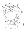
- Fig. 2 shows schematically a large diesel engine according to the present invention, which diesel engine is formed as a two-stroke large diesel engine having a plurality of cylinders and exhaust gas turbochargers as described by Fig. 1 .
- the large diesel engine which is referred to in the whole of the following with the reference numeral 1
- the large diesel engine includes a reducing means 9, 91, 92, 93 which allows in the present example to reduce the exhaust gas-flow through the first exhaust gas turbocharger 81.
- the large diesel engine 1 may comprise more than three cylinders 2, for example six, twelve, fourteen or any other number of cylinders 2 and, of cause, the large diesel engine 1 may have more than two exhaust gas turbochargers 8.
- a reducing-means 9, 91, 92, 93 for reducing an exhaust gas-flow in the present example an exhaust gas-flow through the first exhaust gas turbocharger 81 is provided to reduce the exhaust gas-flow through the first exhaust gas turbocharger 8, in particular in dependence of a given value of an operational parameter of the large diesel engine 1.
- the reducing-means 9, 91, 92, 93 is provided at a first exhaust-gas-inlet 810 of the first exhaust gas turbocharger 81. It goes without saying that in another embodiment of the present invention the reducing-means 9, 91, 92, 93 can also be provided at an first exhaust-gas-outlet 811 of the first exhaust gas turbocharger 81 and / or at a second exhaust-gas-inlet 820 and / or at an second exhaust gas outlet 821 of the second exhaust gas turbocharger 82.
- the reducing-means 9, 91, 92, 93 is provided at the exhaust-gas-manifold 10 of the two-stroke large diesel engine.
- the reducing-means 9 is a controllable gas-valve 91, wherein a sensor 900 for measuring the operational parameter is provided, which sensor is in the present example of Fig. 2 a temperature sensor 900.
- the large diesel engine according to Fig. 2 additionally comprises a control unit for controlling the reducing-means 91 in dependence of the operational parameter, which is in the present example the temperature of the exhaust gas 6 for adjusting a turbocharger efficiency E to a given efficiency value.
- a fail-safe-system is also provided to prevent an overpressure in the cylinder 2. For reasons of clarity, both, the fail-safe-system and the control unit are not shown in Fig. 2 .
- the first exhaust gas turbocharger 81 can be cut out by the controllable gas-valve 91.
- the cutting out of the first exhaust gas turbocharger 81 reduces the effective nozzle area increasing the pressure ratio across the operating turbine of the remaining second exhaust gas turbocharger 82 to values corresponding to an optimised operational state of the large diesel engine 1. That is a turbocharger efficiency E of the second exhaust gas turbocharger 82 is adjusted to a to a given efficiency value.
- the adjustment of the turbocharger efficiency E is shown in Fig. 3 .
- the diagram of Fig. 3 displays the turbocharger efficiency E of the turbochargers 8 of the large diesel engine 1 in dependence of the load L of the large diesel engine 1 in the operating state, wherein in Fig. 4 a component temperature T as a function of trapped air to fuel ratio ⁇ is displayed.
- Curve B in Fig. 3 and Point B of curve C in Fig. 4 correspond to operation states of the large diesel engine 1 in which all turbochargers 8 of the large diesel engine 1 are in operation. It can be clearly seen that, in case that all turbochargers 8 are in operation, the turbocharger efficiency will decrease, in particular in a load range below 50%, and correspondingly, according to Fig. 4 the trapped air to fuel ratio will also decrease and will lead to a higher exhaust gas temperature T and, as a result to higher combustion chamber component temperatures T.
- the effect of cutting out one or more turbocharger 8 is represented by curve A of Fig. 3 and points A in curve C of Fig. 4 , respectively.
- Cutting out one or more turbochargers 8 in the low load range will according to Fig. 3 lead to a maximum of the turbocharger efficiency E in the low load range, for example at about 50% of a maximum load of the large diesel engine 1, and will lead in the same time to a decrease of the exhaust gas temperature according to point A in curve C as shown in Fig. 4 .
Landscapes
- Engineering & Computer Science (AREA)
- General Engineering & Computer Science (AREA)
- Chemical & Material Sciences (AREA)
- Combustion & Propulsion (AREA)
- Mechanical Engineering (AREA)
- Life Sciences & Earth Sciences (AREA)
- Sustainable Development (AREA)
- Supercharger (AREA)
- Output Control And Ontrol Of Special Type Engine (AREA)
Priority Applications (1)
| Application Number | Priority Date | Filing Date | Title |
|---|---|---|---|
| EP09152802A EP2098708A1 (fr) | 2008-03-06 | 2009-02-13 | Procédé pour le fonctionnement d'un moteur diesel à deux temps à balayage longitudinal et moteur diesel à deux temps à balayage longitudinal |
Applications Claiming Priority (2)
| Application Number | Priority Date | Filing Date | Title |
|---|---|---|---|
| EP08152400 | 2008-03-06 | ||
| EP09152802A EP2098708A1 (fr) | 2008-03-06 | 2009-02-13 | Procédé pour le fonctionnement d'un moteur diesel à deux temps à balayage longitudinal et moteur diesel à deux temps à balayage longitudinal |
Publications (1)
| Publication Number | Publication Date |
|---|---|
| EP2098708A1 true EP2098708A1 (fr) | 2009-09-09 |
Family
ID=39721896
Family Applications (1)
| Application Number | Title | Priority Date | Filing Date |
|---|---|---|---|
| EP09152802A Withdrawn EP2098708A1 (fr) | 2008-03-06 | 2009-02-13 | Procédé pour le fonctionnement d'un moteur diesel à deux temps à balayage longitudinal et moteur diesel à deux temps à balayage longitudinal |
Country Status (6)
| Country | Link |
|---|---|
| EP (1) | EP2098708A1 (fr) |
| JP (1) | JP2009216093A (fr) |
| KR (1) | KR20090096315A (fr) |
| CN (1) | CN101526025A (fr) |
| BR (1) | BRPI0900518A2 (fr) |
| RU (1) | RU2483220C2 (fr) |
Cited By (3)
| Publication number | Priority date | Publication date | Assignee | Title |
|---|---|---|---|---|
| FR2972023A1 (fr) * | 2011-02-28 | 2012-08-31 | Andre Chaneac | Double suralimentation pour un moteur deux temps |
| CN105781809A (zh) * | 2016-05-06 | 2016-07-20 | 哈尔滨工程大学 | 一种船舶二冲程柴油机双涡轮egr系统及方法 |
| EP3098415A4 (fr) * | 2014-01-17 | 2017-10-11 | IHI Corporation | Moteur à deux temps à balayage équicourant |
Families Citing this family (7)
| Publication number | Priority date | Publication date | Assignee | Title |
|---|---|---|---|---|
| JP5651945B2 (ja) * | 2009-12-04 | 2015-01-14 | ヤマハ株式会社 | 音響処理装置 |
| US10132688B2 (en) | 2010-12-17 | 2018-11-20 | General Electric Company | System and method for detecting spall within a turbine engine |
| EP2522843B1 (fr) * | 2011-05-12 | 2014-09-03 | Ford Global Technologies, LLC | Moteur à combustion interne chargé doté de collecteurs de gaz d'échappement séparés et procédé de fonctionnement d'un tel moteur à combustion interne |
| CN102705069B (zh) * | 2012-06-07 | 2014-11-05 | 阮派烈 | 一种发动机 |
| JP6071583B2 (ja) * | 2013-01-24 | 2017-02-01 | 三菱重工業株式会社 | 制御装置、過給システム、制御方法およびプログラム |
| CN104454180A (zh) * | 2014-09-30 | 2015-03-25 | 董伟冈 | 一种内燃机动力装置、发动机以及该内燃机动力装置的运行方法 |
| JP7329488B2 (ja) * | 2019-11-15 | 2023-08-18 | エムエーエヌ・エナジー・ソリューションズ・フィリアル・アフ・エムエーエヌ・エナジー・ソリューションズ・エスイー・ティスクランド | クロスヘッド式大型低速ターボ過給2ストロークユニフロー掃気内燃機関及びこれを動作させる方法 |
Citations (15)
| Publication number | Priority date | Publication date | Assignee | Title |
|---|---|---|---|---|
| GB569270A (en) * | 1942-11-09 | 1945-05-15 | Goetaverken Ab | Improvements in power plants |
| GB941220A (en) * | 1960-06-15 | 1963-11-06 | Sulzer Ag | Multi-cylinder supercharged internal combustion engines |
| JPS59147823A (ja) * | 1983-02-10 | 1984-08-24 | Mitsubishi Heavy Ind Ltd | 排気タ−ボ過給4サイクル機関 |
| JPS60198332A (ja) * | 1984-03-22 | 1985-10-07 | Ishikawajima Harima Heavy Ind Co Ltd | 舶用デイ−ゼル内燃機関の過給制御方法 |
| WO1994004804A1 (fr) * | 1992-08-13 | 1994-03-03 | Man B&W Diesel A/S | Procede pour commander un gros moteur a combustion interne turbocompresse a deux temps et moteur utilise dans ce procede |
| EP0653558A1 (fr) | 1993-11-12 | 1995-05-17 | New Sulzer Diesel AG | Procédé pour diminuer le contenu en oxyde d'azote des gaz d'échappement d'un moteur à combustion interne du type Diesel à deux temps et ce moteur |
| JPH09256814A (ja) * | 1996-03-22 | 1997-09-30 | Mitsubishi Heavy Ind Ltd | ディーゼル機関プラント |
| DE19809618A1 (de) * | 1998-03-06 | 1999-09-09 | Man B & W Diesel Gmbh | Zweitaktmotor |
| US6062178A (en) * | 1998-05-20 | 2000-05-16 | Southwest Research Institute | Method of operating uni-flow two-cycle engine during reduced load conditions |
| EP0967371B1 (fr) | 1998-06-26 | 2003-02-26 | Wärtsilä Schweiz AG | Moteur diesel du type à deux temps |
| EP1375868A1 (fr) * | 2002-06-26 | 2004-01-02 | Borg Warner Inc. | Dispositif à frein moteur pour un moteur à combustion interne à suralimentation par turbosoufflante |
| EP1380737A1 (fr) * | 2002-07-09 | 2004-01-14 | Wärtsilä Schweiz AG | Procédé de fonctionnement d'un moteur à combustion interne à deux temps à piston alternatif |
| US20050000216A1 (en) * | 2003-05-06 | 2005-01-06 | Thomas Bleile | Method and device for regulating the boost pressure of an internal combustion engine |
| GB2410060A (en) * | 2004-01-14 | 2005-07-20 | Lotus Car | A two-stroke compression-ignition internal combustion engine |
| EP1777388A1 (fr) * | 2005-10-21 | 2007-04-25 | Wärtsilä Schweiz AG | Moteur à deux temps |
Family Cites Families (11)
| Publication number | Priority date | Publication date | Assignee | Title |
|---|---|---|---|---|
| SU676745A1 (ru) * | 1977-11-09 | 1979-07-30 | Харьковский Институт Механизации И Электрификации Сельского Хозяйства | Двигатель внутреннего сгорани |
| JPH0388918A (ja) * | 1989-08-31 | 1991-04-15 | Mazda Motor Corp | ターボ過給機付エンジンの制御装置 |
| US5289684A (en) * | 1991-08-02 | 1994-03-01 | Toyota Jidosha Kabushiki Kaisha | Charging pressure control apparatus for an internal combustion engine with a dual turbocharger system |
| JP3147430B2 (ja) * | 1991-09-10 | 2001-03-19 | 石川島播磨重工業株式会社 | シーケンシャルターボの予回転装置 |
| JP2578819Y2 (ja) * | 1991-11-26 | 1998-08-20 | 三菱自動車工業株式会社 | ディーゼルエンジンの燃料噴射装置 |
| JPH07189717A (ja) * | 1993-12-24 | 1995-07-28 | Mitsubishi Heavy Ind Ltd | 過給機付内燃機関 |
| JP2001012234A (ja) * | 1999-06-30 | 2001-01-16 | Fuji Heavy Ind Ltd | 過給機付きエンジンの排気装置 |
| JP2006194253A (ja) * | 2000-12-27 | 2006-07-27 | Yanmar Co Ltd | 排気浄化装置を備えた内燃機関 |
| JP2002266630A (ja) * | 2001-03-07 | 2002-09-18 | Isuzu Motors Ltd | 排気ガス浄化システム及び排気ガス浄化方法 |
| US20070119168A1 (en) * | 2004-01-14 | 2007-05-31 | Turner James W G | Turbocharged internal combustion engine |
| RU2262607C1 (ru) * | 2004-02-09 | 2005-10-20 | Васильев Евгений Жоресович | Система настройки и регулирования давлений наддува двигателя внутреннего сгорания с турбонаддувом |
-
2009
- 2009-02-13 EP EP09152802A patent/EP2098708A1/fr not_active Withdrawn
- 2009-02-17 KR KR1020090012826A patent/KR20090096315A/ko not_active Application Discontinuation
- 2009-03-05 BR BRPI0900518-8A patent/BRPI0900518A2/pt not_active IP Right Cessation
- 2009-03-05 RU RU2009107973/06A patent/RU2483220C2/ru not_active IP Right Cessation
- 2009-03-05 JP JP2009051448A patent/JP2009216093A/ja active Pending
- 2009-03-05 CN CN200910126669A patent/CN101526025A/zh active Pending
Patent Citations (15)
| Publication number | Priority date | Publication date | Assignee | Title |
|---|---|---|---|---|
| GB569270A (en) * | 1942-11-09 | 1945-05-15 | Goetaverken Ab | Improvements in power plants |
| GB941220A (en) * | 1960-06-15 | 1963-11-06 | Sulzer Ag | Multi-cylinder supercharged internal combustion engines |
| JPS59147823A (ja) * | 1983-02-10 | 1984-08-24 | Mitsubishi Heavy Ind Ltd | 排気タ−ボ過給4サイクル機関 |
| JPS60198332A (ja) * | 1984-03-22 | 1985-10-07 | Ishikawajima Harima Heavy Ind Co Ltd | 舶用デイ−ゼル内燃機関の過給制御方法 |
| WO1994004804A1 (fr) * | 1992-08-13 | 1994-03-03 | Man B&W Diesel A/S | Procede pour commander un gros moteur a combustion interne turbocompresse a deux temps et moteur utilise dans ce procede |
| EP0653558A1 (fr) | 1993-11-12 | 1995-05-17 | New Sulzer Diesel AG | Procédé pour diminuer le contenu en oxyde d'azote des gaz d'échappement d'un moteur à combustion interne du type Diesel à deux temps et ce moteur |
| JPH09256814A (ja) * | 1996-03-22 | 1997-09-30 | Mitsubishi Heavy Ind Ltd | ディーゼル機関プラント |
| DE19809618A1 (de) * | 1998-03-06 | 1999-09-09 | Man B & W Diesel Gmbh | Zweitaktmotor |
| US6062178A (en) * | 1998-05-20 | 2000-05-16 | Southwest Research Institute | Method of operating uni-flow two-cycle engine during reduced load conditions |
| EP0967371B1 (fr) | 1998-06-26 | 2003-02-26 | Wärtsilä Schweiz AG | Moteur diesel du type à deux temps |
| EP1375868A1 (fr) * | 2002-06-26 | 2004-01-02 | Borg Warner Inc. | Dispositif à frein moteur pour un moteur à combustion interne à suralimentation par turbosoufflante |
| EP1380737A1 (fr) * | 2002-07-09 | 2004-01-14 | Wärtsilä Schweiz AG | Procédé de fonctionnement d'un moteur à combustion interne à deux temps à piston alternatif |
| US20050000216A1 (en) * | 2003-05-06 | 2005-01-06 | Thomas Bleile | Method and device for regulating the boost pressure of an internal combustion engine |
| GB2410060A (en) * | 2004-01-14 | 2005-07-20 | Lotus Car | A two-stroke compression-ignition internal combustion engine |
| EP1777388A1 (fr) * | 2005-10-21 | 2007-04-25 | Wärtsilä Schweiz AG | Moteur à deux temps |
Cited By (3)
| Publication number | Priority date | Publication date | Assignee | Title |
|---|---|---|---|---|
| FR2972023A1 (fr) * | 2011-02-28 | 2012-08-31 | Andre Chaneac | Double suralimentation pour un moteur deux temps |
| EP3098415A4 (fr) * | 2014-01-17 | 2017-10-11 | IHI Corporation | Moteur à deux temps à balayage équicourant |
| CN105781809A (zh) * | 2016-05-06 | 2016-07-20 | 哈尔滨工程大学 | 一种船舶二冲程柴油机双涡轮egr系统及方法 |
Also Published As
| Publication number | Publication date |
|---|---|
| BRPI0900518A2 (pt) | 2009-11-17 |
| CN101526025A (zh) | 2009-09-09 |
| JP2009216093A (ja) | 2009-09-24 |
| RU2483220C2 (ru) | 2013-05-27 |
| KR20090096315A (ko) | 2009-09-10 |
| RU2009107973A (ru) | 2010-09-10 |
Similar Documents
| Publication | Publication Date | Title |
|---|---|---|
| EP2098708A1 (fr) | Procédé pour le fonctionnement d'un moteur diesel à deux temps à balayage longitudinal et moteur diesel à deux temps à balayage longitudinal | |
| JP6273051B2 (ja) | ポーテッドのユニフロー掃気対向ピストンエンジンを操作する方法 | |
| US8186334B2 (en) | 6-cycle engine with regenerator | |
| JP6117695B2 (ja) | 対向ピストンエンジンのためのegr構造 | |
| EP2808522B1 (fr) | Procédé et système de fonctionnement d'un moteur à combustion interne | |
| JP4898912B2 (ja) | 火花点火機関の運転方法 | |
| US8439021B2 (en) | EGR system for an internal combustion engine | |
| SE1050854A1 (sv) | Arrangemang för att spruta in ett reduktionsmedel i en avgasledning hos en förbränningsmotor | |
| EP3559431B1 (fr) | Procédé de commande d'un moteur à combustion interne | |
| KR102242378B1 (ko) | 대형 2행정 단류 소기식 기체 연료 엔진 및 그 제어 방법 | |
| US8166757B2 (en) | Engine with internal EGR system | |
| EP3596329B1 (fr) | Moteur à combustion interne et procédé d'exploitation d'un tel moteur à combustion interne | |
| CN102216592B (zh) | 控制活塞发动机的涡轮增压器速度的方法以及涡轮增压活塞发动机的控制系统 | |
| DK180131B1 (en) | A LARGE TWO-STROKE UNIFLOW SCAVENGED GASEOUS FUELED ENGINE AND METHOD FOR REDUCING PREIGNITION / DIESEL-KNOCK | |
| JP2013238246A (ja) | 長手方向に掃気される2ストロークの大きなディーゼル機関の作動方法、及び長手方向に掃気される大きなディーゼル機関 | |
| WO2012107960A1 (fr) | Dispositif de recirculation des gaz d'échappement | |
| KR101475834B1 (ko) | 대형, 크로스헤드 왕복 피스톤 내연기관을 작동하기 위한 방법 및 그러한 적합한 내연기관 | |
| US11512672B2 (en) | Internal combustion engine system operable in at least two operating modes | |
| CN101532419A (zh) | 二冲程内燃机中燃烧换气(扫气)的方法 | |
| CN203769966U (zh) | 机械增压的内燃发动机 | |
| JP7129755B2 (ja) | 舶用ディーゼルエンジン | |
| KR101734169B1 (ko) | 길이 방향으로 소기되는 2행정 대형 디젤 엔진의 작동 방법 | |
| EP2749758B1 (fr) | Procédé et appareil pour contrôler un système d'EGR et un catalyseur SCR en function du coût de carburant et d'additif | |
| CN111094724B (zh) | 内燃机和用于控制这种内燃机的方法 | |
| JP2012127294A (ja) | 内燃機関の制御装置 |
Legal Events
| Date | Code | Title | Description |
|---|---|---|---|
| PUAI | Public reference made under article 153(3) epc to a published international application that has entered the european phase |
Free format text: ORIGINAL CODE: 0009012 |
|
| AK | Designated contracting states |
Kind code of ref document: A1 Designated state(s): AT BE BG CH CY CZ DE DK EE ES FI FR GB GR HR HU IE IS IT LI LT LU LV MC MK MT NL NO PL PT RO SE SI SK TR |
|
| AX | Request for extension of the european patent |
Extension state: AL BA RS |
|
| 17P | Request for examination filed |
Effective date: 20100309 |
|
| AKX | Designation fees paid |
Designated state(s): AT BE BG CH CY CZ DE DK EE ES FI FR GB GR HR HU IE IS IT LI LT LU LV MC MK MT NL NO PL PT RO SE SI SK TR |
|
| 17Q | First examination report despatched |
Effective date: 20100422 |
|
| STAA | Information on the status of an ep patent application or granted ep patent |
Free format text: STATUS: THE APPLICATION IS DEEMED TO BE WITHDRAWN |
|
| 18D | Application deemed to be withdrawn |
Effective date: 20151125 |