EP1372013A1 - Bildvergleichseinrichtung, bildvergleichsverfahren und programm mit auf computer ablaufendem bildvergleich - Google Patents
Bildvergleichseinrichtung, bildvergleichsverfahren und programm mit auf computer ablaufendem bildvergleich Download PDFInfo
- Publication number
- EP1372013A1 EP1372013A1 EP02712419A EP02712419A EP1372013A1 EP 1372013 A1 EP1372013 A1 EP 1372013A1 EP 02712419 A EP02712419 A EP 02712419A EP 02712419 A EP02712419 A EP 02712419A EP 1372013 A1 EP1372013 A1 EP 1372013A1
- Authority
- EP
- European Patent Office
- Prior art keywords
- image
- comparison
- observation
- specimen
- reference image
- Prior art date
- Legal status (The legal status is an assumption and is not a legal conclusion. Google has not performed a legal analysis and makes no representation as to the accuracy of the status listed.)
- Withdrawn
Links
Images


Classifications
-
- G—PHYSICS
- G02—OPTICS
- G02B—OPTICAL ELEMENTS, SYSTEMS OR APPARATUS
- G02B21/00—Microscopes
- G02B21/18—Arrangements with more than one light path, e.g. for comparing two specimens
-
- G—PHYSICS
- G02—OPTICS
- G02B—OPTICAL ELEMENTS, SYSTEMS OR APPARATUS
- G02B21/00—Microscopes
- G02B21/36—Microscopes arranged for photographic purposes or projection purposes or digital imaging or video purposes including associated control and data processing arrangements
- G02B21/365—Control or image processing arrangements for digital or video microscopes
- G02B21/367—Control or image processing arrangements for digital or video microscopes providing an output produced by processing a plurality of individual source images, e.g. image tiling, montage, composite images, depth sectioning, image comparison
Definitions
- the present invention relates to an image comparison apparatus and image comparison method which compare a reference image as a sample with a comparison image as a comparison target, and a program for causing a computer to execute image comparison.
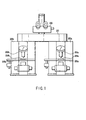
- This comparison microscope includes two microscope bodies 202a and 202b.
- the microscope bodies 202a and 202b respectively have object lenses 203a and 203b.
- Specimens 204a ad 204b such as printed matter are placed on stages 205a and 205b corresponding to the object lenses 203a and 203b.
- a common comparison lens barrel 201 is connected to the microscope bodies 202a and 202b. This arrangement allows simultaneous observation of observation images formed by the microscope bodies 202a and 202b through an observation lens barrel 200.
- the specimen 204a serving as a sample is placed on the stage 205a of the microscope body 202a.
- the specimen 204b serving as a comparison target is placed on the stage 205b of the microscope body 202b.
- An observation image of the right half of the specimen 204a in the visual field is abutted against an observation image of the left half of the specimen 204b in the visual field to allow observation of these images as one observation image through the observation lens barrel 200. This makes it possible to compare the left and right observation images and allow the user to easily check whether or not the specimens 204a and 204b are identical.
- An apparatus using comparison microscopes like those described above requires a real specimen serving as a sample as well as a specimen serving as a comparison target for which counterfeit identification is required. Therefore, an observer who has no specimen as a sample cannot perform comparing operation, and has a difficulty in counterfeit identification.
- variations in brightness and color between the optical systems of the microscope bodies 202a and 202b sometimes make it difficult to compare a comparison image with a reference image, It is important for counterfeit identification to facilitate recognition of the difference between images by positioning them for comparison. Such positioning, however, requires cumbersome operation, e.g., moving the positions of the specimens 204a and 204b on the stages 205a and 205b.
- an image comparison apparatus for performing comparison and observation using reference images stored as digital images is known (see Jpn. Pat. Appln. KOKAI Publication No. 06-6807).
- this image comparison apparatus a plurality of images captured from a TV camera are stored as digital data. Subsequently, a half portion of a reference image and a half portion of a comparison image are extracted and pasted together to display them as one image on a monitor. This makes it possible to easily check whether or not the left and right images are identical.
- an observation window is split into two parts and two images are displayed therein to be compared in order to prevent a decrease in resolution.
- half images must be compared with each other, and hence comparison/observation of images must be performed at least twice.
- the observer may be confused about which image is a reference image or comparison image.
- an oversight and the like may occur.
- An image comparison apparatus is characterized by comprising observation image capturing means for capturing at least one of a macroscopic observation image of a specimen or a microscopic observation image of the specimen, photographing means for photographing an observation image captured by the observation image capturing means, recording means for recording a reference image prepared in advance, and display means for displaying the observation image photographed by the photographing means as a comparison image, and also displaying the reference image recorded on the recording means on the display means so as to allow comparison between the comparison image and the reference image.
- An image comparison apparatus is characterized by comprising a macro-observation unit which captures a macroscopic observation image of a specimen, a micro-observation unit which captures a microscopic observation image of the specimen, a stage which moves the specimen between the macro-observation unit and the micro-observation unit, a camera which photographs an observation image of a specimen on the stage which is captured by the macro-observation unit and the micro-observation unit, optical path switching means for switching an optical path from the macro-observation unit or the micro-observation unit to the camera, a recording medium which records an observation image photographed by the camera as a reference image, and display means for displaying the observation image photographed by the camera as a comparison image and also displaying the reference image recorded on the recording medium so as to allow comparison between the images.
- An image comparison method is characterized by comprising capturing at least one of a macroscopic observation image and a microscopic observation image of a specimen, photographing the captured observation image, and displaying an entire or part of a comparison image obtained from the photographed observation image and an entire or part of a reference image prepared in advance so as to allow comparison therebetween.
- An image comparison method is characterized by comprising capturing a macroscopic observation image or a microscopic observation image of a specimen, photographing the captured observation image, and displaying an addition image obtained by adding a comparison image obtained from the photographed observation image to a reference image prepared in advance at an arbitrary ratio.
- An image comparison method is characterized by comprising capturing a macroscopic observation image or a microscopic observation image of a specimen, photographing the captured observation image, and alternately displaying a comparison image obtained from the photographed observation image and a reference image prepared in advance at predetermined time intervals.
- An image comparison method is characterized by comprising capturing a macroscopic observation image or a microscopic observation image of a specimen, photographing the captured observation image, performing subtraction between the photographed observation image and a reference image prepared in advance, and performing displaying on the basis of the subtraction result.
- An image comparison method which is applied to a system in which at least two image comparison apparatuses and an image server capable of storing at least one image are connected through a network capable of data communication is characterized in that in each of the image comparison apparatuses, a reference image used for comparison with a comparison image acquired from a specimen can be read out from the image server through the network.
- a computer program product is characterized by capturing at least one of a macroscopic observation image and a microscopic observation image of a specimen, photographing the captured observation image, and displaying an entire or part of a comparison image obtained from the photographed observation image and an entire or part of a reference image prepared in advance so as to allow comparison therebetween.
- a computer program product is characterized by capturing a macroscopic observation image or a microscopic observation image of a specimen, photographing the captured observation image, and displaying an addition image obtained by adding a comparison image obtained from the photographed observation image to a reference image prepared in advance at an arbitrary ratio.
- a computer program product is characterized by capturing a macroscopic observation image or a microscopic observation image of a specimen, photographing the captured observation image, and alternately displaying a comparison image obtained from the photographed observation image and a reference image prepared in advance at predetermined time intervals.
- a computer program product is characterized by capturing a macroscopic observation image or a microscopic observation image of a specimen, photographing the captured observation image, performing subtraction between the photographed observation image and a reference image prepared in advance, and performing displaying on the basis of the subtraction result.
- a computer program product which is applied to a system in which at least two image comparison apparatuses and an image server capable of storing at least one image are connected through a network capable of data communication, characterized in that in each of the image comparison apparatuses, a reference image used for comparison with a comparison image acquired from a specimen can be read out from the image server through the network.
- An image comparison method is characterized in that a display window designated by a control apparatus connected, through a network capable of data communication, to an apparatus including photographing means for photographing an observation image of a specimen, display means for comparing the photographed observation image, and means for communicating a display method for image comparison is displayed by communication.
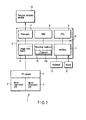
- FIG. 2 is a block diagram showing a microscopic image comparison apparatus as an embodiment of an image comparison apparatus according to the present invention.
- an observation device 1 for observing a specimen includes a micro-observation unit 2 which serves as a micro-observation image capturing means for capturing a microscopic observation image of the specimen so as to capture a microscopic observation image, a macro-observation unit 3 which serves as a macro-observation image capturing image for capturing a macroscopic observation image of the specimen, and a TV camera 4 serving as a photographing means.
- the observation device 1 sends out the observation image captured by the micro-observation unit 2 or macro-observation unit 3, as a digital image, to a personal computer body 5 serving as a control means through the TV camera 4.
- the personal computer body 5 includes an image input board 6, video card 7, RAM 8, CPU 9, recording medium 10, interface 11, and bus 12.
- the personal computer body 5 stores, in the RAM 8, the digital image captured from the TV camera 4 into the image input board 6, or displays the image as a still or live image on a personal computer monitor 13 serving as a display means through the video card 7 (a live image is displayed at the video rate of the TV camera 4).
- a plurality of digitalized reference images which are prepared in advance are recorded on the recording medium 10.
- a program 10a such as image comparison software is also recorded on the recording medium 10.
- the program 10a is temporarily recorded on the RAM 8 and executed by the CPU 9 to perform image comparison processing.
- a keyboard 14 and mouse 15 are connected to the interface 11. The keyboard 14 and mouse 15 are used to input instructions when the program 10a is to be executed.
- FIG. 3 is a view showing the system arrangement of the microscopic image comparison apparatus in FIG. 2.
- the same reference numerals as in FIG. 3 denote the same parts in FIG. 2.
- the micro-observation unit 2 is used as a micro-observation image capturing means for observation of elaborate printing and treatment of a specimen upon enlarging it.
- the micro-observation unit 2 has an object lens 21 opposed to the specimen (not shown) placed on a base 20.
- An elaborate printing or treatment state of the specimen is enlarged through the object lens 21 and can be visually observed through an eyepiece 22. This state is sensed by the TV camera 4 and captured into the personal computer body 5.
- the micro-observation unit 2 includes a polarization illumination source 23, epi-illumination source 24, transmitted illumination source 25, epi-fluorescence illumination source 26, and focal illumination source 27.
- the polarization illumination source 23 irradiates the specimen placed on the base 20 with polarized illumination light along the optical axis through the object lens 21.
- the epi-illumination source 24 is so placed as to irradiate the specimen with light from a position located outside the optical axis of the object lens 21.
- the transmitted illumination source 25 emits light from the inside of the base 20 toward the object lens 21 to allow observation of the outer shape of the specimen or an image transmitted through the specimen.
- the epi-fluorescence illumination source 26 is an illumination source for observation of a fluorescent image.
- This illumination source makes it possible to observe a special print obtained by applying fluorescent printing to the specimen.
- the focal illumination source 27 is placed at a position where the specimen can be obliquely illuminated with light. This illumination source is used to observe special treatment of producing an embossed pattern on the specimen, e.g., imprinting on the specimen.
- a micro control box 28 is used to turn on/off the polarization illumination source 23, epi-illumination source 24, transmitted illumination source 25, epi-fluorescence illumination source 26, and focal illumination source 27 and adjust their brightness.
- the macro-observation unit 3 is used as a macro-observation image capturing means for observing the specimen in a relatively wide visual field and range.
- the macro-observation unit 3 has a macrolens 29 opposed to the specimen (not shown) placed on a base 281.
- An image of the specimen is guided to the optical path on the micro-observation unit 2 side through the macrolens 29 and a macro focusing handle 36.
- the image of the specimen guided to the optical path on the micro-observation unit 2 side can be visually observed through the eyepiece 22. This image is also sensed by the TV camera 4 and captured in the personal computer body 5.
- the macro-observation unit 3 includes, as illumination devices, a polarization illumination source 30, epi-illumination source 31, transmitted illumination source 32, epi-fluorescence illumination source 33, and focal illumination source 34.
- the polarization illumination source 30 irradiates the specimen placed on the base 281 with polarized illumination light along the optical axis through the macrolens 29.
- the epi-illumination source 31 is so placed as to irradiate the specimen with light from a position located outside the optical axis of the macrolens 29.
- the transmitted illumination source 32 emits light from the inside of the base 281 toward the macrolens 29 to allow observation of the outer shape of the specimen or an image transmitted through the specimen.
- the epi-fluorescence illumination source 33 is an illumination source for observation of a fluorescent image.
- This illumination source makes it possible to observe a special print obtained by applying fluorescent printing to the specimen.
- the focal illumination source 34 is placed at a position where the specimen can be obliquely illuminated with light. This illumination source is used to observe special treatment of producing an embossed pattern on the specimen, e.g., imprinting on the specimen.
- a macro control box 35 is used to turn on/off the polarization illumination source 30, epi-illumination source 31, transmitted illumination source 32, epi-fluorescence illumination source 33, and focal illumination source 34 and adjust their brightness.
- FIG. 4 shows an example of a GUI (Graphical User Interface) 41 displayed when the image comparison software of the program 10a recorded on the recording medium 10 is activated.
- GUI 41 Graphic User Interface
- the GUI 41 is displayed as a Windows dialog using an operation system such as Windows of Microsoft.
- the GUI 41 has a still image display area 42 serving as the first image display area and a live image display area 43 serving as the second image display area.
- a digital image as a still image can be displayed as a reference image in the still image display area 42.
- the reference image may be an image obtained by photographing a text letter or a counterfeit portion of a print specimen, or an image obtained by photographing, with the TV camera 4, a micro-observation image or macro-observation image of the specimen captured by the micro-observation unit 2 or macro-observation unit 3.
- These reference images are recorded in advance on the recording medium 10 of the personal computer body 5.
- a live image serving as a comparison image can be displayed in the live image display area 43.
- a comparison image is an image of a specimen with which the user wants to compare a reference image (or which is to be compared with the reference image).
- the comparison image is a live image (or still image) obtained by photographing, with the TV camera 4, the micro-observation image or macro-observation image of the specimen which is captured by the micro-observation unit 2 or macro-observation unit 3.
- an image which is photographed by the TV camera 4 to obtain a comparison image may be an image obtained from either the micro-observation unit 2 or the macro-observation unit 3.
- the observer can arbitrarily select one of these images which is to be observed, in accordance with a purpose.
- the live image display area 43 allows a live image to be displayed. However, after the specimen is moved and its observation position is determined, the image in this area can also be temporarily displayed as a still image.
- the GUI 41 has an observation image display area 44 as the third image display area.
- the still and live images displayed in the still image display area 42 and live image display area 43 can be displayed by various display methods to be described below.
- FIGS. 5A to 10C are views for explaining various display examples in the observation image display area 44.
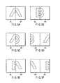
- FIGS. 5A to 5F show the first display example in a case wherein the reference image in the still image display area 42 and the comparison image in the live image display area 43 are placed side by side in the observation image display area 44.
- FIG. 5A is a view showing the reference image in the still image display area 42. The left half of this image is a left still image portion 42L, and the right half is a right still image portion 42R.
- FIG. 5B is a view showing the comparison image in the live image display area 43. The left half of this image is a left live image portion 43L, and the right half is a right live image portion 43R.
- FIG. 5C is a view showing an observation image in the observation image display area 44.
- a reference image of the left still image portion 42L is displayed as the left half of the observation image
- a comparison image of the right live image portion 43R is displayed as the right half of the observation image.
- a comparison image of the right live image portion 43R is displayed in the left half of the area
- a comparison image of the right live image portion 43R is displayed in the right half of the area.
- a comparison image of the right live image portion 43R is displayed in the left half of the area
- a reference image of the left still image portion 42L is displayed in the right half of the area.
- FIG. 5C is a view showing an observation image in the observation image display area 44.
- a reference image of the left still image portion 42L is displayed as the left half of the observation image
- a comparison image of the right live image portion 43R is displayed as the right half of the observation image.
- a comparison image of the right live image portion 43R is displayed in the left half of the
- a comparison image of the left live image portion 43L is displayed in the left half of the area, and a reference image of the right still image portion 42R is displayed in the right half of the area.
- a reference image of the right still image portion 42R is displayed in the left half of the area, and a comparison image of the left live image portion 43L is displayed in the right half of the area.
- images photographed by the TV camera 4 are displayed in real time (at the video rate). This allows the observer to adjust the left still image portion 42L or right still image portion 42R to a desired observation position while moving the specimen. When the observation image is completely positioned, the left and right images can be compared as still images.
- the window is split into left and right portions at the same ratio.
- this ratio can be changed.
- the width of the left still image portion 42L may be decreased, and the width of the right live image portion 43R may be increased.
- FIGS. 6A to 6F show the second display example in a case wherein a reference image in the still image display area 42 and a comparison image in the live image display area 43 are vertically arranged in the observation image display area 44 to be compared with each other.
- FIG. 6A shows the reference image in the still image display area 42.
- the upper and lower halves of this image are an upper still image portion 42U and lower still image portion 42D, respectively.
- FIG. 6B shows the comparison image in the live image display area 43.
- the upper and lower halves of this image are an upper live image portion 43U and lower live image portion 43D, respectively.
- FIG. 6C shows the observation image in the observation image display area 44.
- the upper half of the observation image is displayed as a reference image of the upper still image portion 42U; and the lower half, as a comparison image of the lower live image portion 43D.
- the upper half is displayed as a comparison image of the lower live image portion 43D; and the lower half, as a reference image of the upper still image portion 42U.
- the upper half is displayed as a comparison image of the upper live image portion 43U; and the lower half, as a reference image of the lower still image portion 42D.
- the upper half is displayed as a reference image of the lower still image portion 42D; and the lower half, as a comparison image of the upper live image portion 43U.
- the images photographed by the TV camera 4 are displayed in real time (at the video rate). This allows the observer to adjust the upper still image portion 42U or lower still image portion 42D to a desired observation position while moving the specimen. When the observation image is completely positioned, the left and right images can be temporarily compared as still images.
- the widows shown in FIGS. 5A to 5F and FIGS. 6A to 6F can be easily switched by clicking a "split display" icon 45 on the GUI 41.
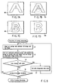
- FIGS. 7A to 7D show the third display example showing a method in a case wherein a reference image in the still image display area 42 and a comparison image in the live image display area 43 are overlapped (image addition) in the observation image display area 44 to be compared with each other.
- FIG. 7A shows an observation image in the observation image display area 44. Referring to FIG. 7A, only a still image 42A which is a reference image in the still image display area 42 is displayed.
- FIG. 7B shows an example of an overlap image 46a.
- a live image 43B (see FIG. 7D) which is a comparison image in the live image display area 43 is displayed upon being superimposed on the still image 42A at a predetermined ratio (this processing will be referred to as "overlap processing" hereinafter).
- Ia(x, y) the luminance of a given pixel (when the pixel position is represented by (x, y) of the image "A"
- Ib(x, y) the luminance of a pixel of the image "B” at the same position
- the images are added by performing this calculation for all the pixels.
- the overlap image 46a in FIG. 7B since the ratio of the still image 42A is larger than that of the live image 43B, the still image 42A is seen more clearly.
- the ratio of the still image 42A is decreased below that of the live image 43B, the live image 43B is seen more clearly than the still image 42A unlike the overlap image 46a shown in FIG. 7B. That is, as the ratio of the still image 42A is increased, only the still image 42A in FIG. 7A can be seen eventually. As the ratio of the live image 43B is increased, only the live image 43B in FIG. 7D can be seen eventually.
- step S1 the overlap ratio (the default value or previously set value) between the still image 42A and the live image 43B is read out from the recording medium 10.
- This overlap ratio corresponds to the ratio between m and n in the above equation. Note that the operator can easily adjust the overlap ratio by moving a slider 47 on the GUI 41 shown in FIG. 4.
- step S2 the still image 42A and live image 43B are added and synthesized at the read overlap ratio, and the resultant image is displayed in the observation image display area 44. In this case, calculation of a ratio is performed for all the pixels of the images according to the above equation. It is then checked in step S3 whether or not the overlap ratio is changed with the slider. If the overlap ratio is changed with the slider 47, the value designated with the slider 47 is set again as an overlap ratio stored in the RAM 8 or recording medium 10 in step S4.
- step S3 If it is determined in step S3 that the overlap ratio is not changed, the flow advances to step S5 to check whether the overlap processing is to be terminated. If the overlap processing is not terminated, the flow returns to step S3 to repeat the same processing. If the overlap processing is to be terminated, a series of operations in the overlap processing is terminated.
- overlap display is performed by adding and overlapping a reference image and comparison image, e.g., an original and a counterfeit print, thereby helping the observer to visually find the difference between them.
- a reference image and comparison image e.g., an original and a counterfeit print
- FIG. 9 shows the fourth display example in a case wherein a reference image in the still image display area 42 and a comparison image in the live image display area 43 are alternately switched and displayed in the observation image display area 44 at predetermined time intervals to be compared with each other.
- the reference image displayed in the still image display area 42 is displayed as a still image 42E in the observation image display area 44.
- the comparison image displayed in the live image display area 43 is displayed as a live image 43F in the observation image display area 44.
- the still image 42E is displayed.
- Such processing is continuously executed.
- a program for this image switching/display processing can be executed by clicking a predetermined icon on the GUI 41.
- the image switching time can be changed to an arbitrary value by inputting a predetermined time interval through the GUI 41, as described above.
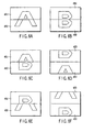
- FIGS. 10A to 10C show the fifth display example in a case wherein different portions of a reference image in the still image display area 42 and a comparison image in the live image display area 43 are highlighted.
- a different portion is detected by the automatic different portion detection method in the following manner.
- a still image 43G displayed in the still image display area 42 is compared with a live image 43H displayed in the live image display area 43.
- the different portion is highlighted as a different-portion-emphasized image 43I in the observation image display area 44.
- a different portion is automatically detected by subtraction between a reference image and a comparison image.
- Ib(x, y) be the luminance of a given pixel of an image "B”
- Ib'(x, y) be the luminance of a pixel of an image "B' " at the same position
- a threshold may be set so that when the luminance is equal to or more than a predetermined value (e.g., 50), it is determined that the corresponding pixels differ from each other. Image subtraction can be done by performing this calculation for all the pixels.
- FIG. 10C shows the different-portion-emphasized image 43I in which the different portion between the images in FIGS. 10A and 10B is highlighted. According to this different-portion-emphasized image, since an area 48 of the still image 43G in FIG. 10A differs from the corresponding portion of the live image 43H in FIG. 10B, the area 48 can be obtained as a different portion 48A. As shown in FIG.
- the area 48A in the different-portion-emphasized image 43I, may be highlighted with a color or graphic pattern so as to be displayed as the area 48A.
- the different-portion-emphasized image 43I only the different area 48A may be displayed, or the different area may be superimposed and displayed on the still image 43G, the live image 43H, or an image obtained by overlapping the still and live images.
- the ratio of the number of pixels that differ in luminance to the number of pixels of the entire image is obtained.
- the difference between the images can then be evaluated by regarding the obtained ratio as the degree of coincidence between the images.
- the different portion between the still image 43G and the live image 43H is highlighted (automatically or manually) to allow the operator to easily grasp the different portion between the two images. This also makes it possible to automatically determine the presence/absence of a different portion. Therefore, this can prevent variations among operators.
- integration processing is preferably performed with respect to the live image 43H.
- this integration processing is performed as follows. Analog images photographed by the TV camera 4 shown in FIG. 2 are sequentially converted into digital images at the video rate by the image input board 6. The sequentially converted digital images are added when they are temporarily stored in a storage device (not shown) in the video card 7. The added digital images are sequentially displayed as the live image 43H on the personal computer monitor 13.
- sequentially converted digital images are stored in the storage device while being added one by one. This makes it possible to increase the luminance of the image.
- flickering noise pixels in an image are averaged to form a smooth image. That is, the noise in the image is reduced.
- an observation image captured by the macro-observation unit 3 for capturing a macroscopic observation image of a specimen or the micro-observation unit 2 for capturing a microscopic observation image of a specimen is photographed by the TV camera 4.
- a comparison image formed from the photographed observation image and a reference image prepared in advance are displayed on the personal computer monitor 13 by various display methods so as to be compared with each other. This makes it possible to easily and efficiently compare and observe a specimen, e.g., special printing on printed matter or ID card.
- various kinds of illumination methods can be selectively used in accordance with specimens. This helps the observer to visually observe a print or treatment which is difficult to see, thereby realizing high-precision image comparison.
- Photographing conditions and the like set when a reference image is captured are preferably stored. Since this allows a comparison image to be captured under the same photographing conditions, there is no sense of congruity between the images to be compared with each other. Therefore, high-precision image comparison can be done.
- a mode suitable for specimens to be compared can be selected from a plurality of image comparison modes (e.g., the first to fifth display examples), image comparison can be performed under optimal conditions.
- a different portion between two images can be highlighted with a color or mark on an image display to attract the attention of the observer. This facilitates visual recognition of the difference between the images.
- a specimen is not limited to printed matter and includes anything that can be stored as a digital image, e.g., a virus or organic cell that can be observed with a microscope.
- the apparatus arrangement and GUI in the second embodiment are the same as those described in the first embodiment with reference to FIGS. 2, 3, and 4, and hence a description thereof will be omitted.
- FIG. 11 shows an observation image displayed in an observation image display area 44 of a GUI 41 in FIG. 4.
- a lattice 51 with a predetermined spacing is displayed on the observation image in the observation image display area 44.
- the lattice 51 may have a 9 ⁇ 6 matrix as shown in FIG. 11 and can be arbitrarily changed to, for example, a 2 ⁇ 2 matrix.
- an image or information about a counterfeit print or the like as a specimen can be used in only this apparatus. Even if, therefore, for example, suspicious objects such as counterfeit prints are found in different places, e.g., various regions, it cannot be checked whether or not they are identical counterfeit prints.
- an image of an original print or the like must be captured in advance as a digital image in each microscopic image comparison apparatus by carrying an original specimen to each region. Such operation must be performed for all the microscopic image comparison apparatuses, and hence it takes much time, resulting in poor operation efficiency.
- a plurality of microscopic image comparison apparatuses are connected to each other through a network.
- a microscopic image comparison apparatus A61 in Tokyo a microscopic image comparison apparatus B62 in Osaka, and a microscopic image comparison apparatus C63 in Fukuoka are installed in the respective regions.
- Personal computer bodies 5 of the microscopic image comparison apparatus A61, microscopic image comparison apparatus B62, and microscopic image comparison apparatus C63 are connected to a network 64 through network interfaces (not shown).
- the network 64 can be a dedicated line such as an ISDN or the Internet.
- An image server 65 is connected to the network 64.
- the image server 65 can perform data communication with the microscopic image comparison apparatus A61, microscopic image comparison apparatus B62, and microscopic image comparison apparatus C63.
- necessary digital images and associated information e.g., a description of a counterfeit portion of a document
- necessary digital images and associated information e.g., a description of a counterfeit portion of a document
- an operator uses the personal computer body 5 of the microscopic image comparison apparatus B62 in Osaka to search the image server 65 for information about the thing suspected as the counterfeit and download necessary information through the network 64. The operator then performs image comparison.
- the image or information is stored in the image server 65. This makes it possible to obtain information about the counterfeit in real time.
- the image sever may automatically send a message or the like to each of the microscopic image comparison apparatuses 61, 62, and 63 so as to allow an operator in each region to always receive the latest information.
- the third embodiment has exemplified the case wherein image files and the like in the image server are shared through the network.
- the following arrangement using a network can also be used.
- An apparatus in each region is used to only photograph an image to be compared and select an image comparison method. These pieces of information are then communicated, through the network, to a control apparatus for centralized data processing.
- the control apparatus communicates a display window for image comparison to the apparatus in each region on the basis of the pieces of information.
- the apparatus in each region may perform image comparison on the basis of the photographed image and the image transmitted from the control apparatus.
- a specimen on the base 281 is compared with a reference image in a wide visual field by using the macro-observation unit 3.
- the specimen is transferred onto the base 20 of the micro-observation unit 2 as needed to compare it with the reference image upon enlarging elaborate printing or treatment.
- these operations can be automatically performed.
- FIG. 13 is a view showing the system arrangement of a microscopic image comparison apparatus according to the fourth embodiment.
- the microscopic image comparison apparatus includes an observation device 69 and image processing device 70.
- the observation device 69 includes a micro-observation unit 71 serving as an integrated micro-observation image capturing means and a macro-observation unit 72 serving as a macro-observation image capturing means.
- the micro-observation unit 71 and macro-observation unit 72 have a common macro/micro motor-driven stage (automatic X-Y stage) 75 on a base (for micro observation) 73 and a base (for macro observation) 74.
- a specimen can be automatically transferred between the micro-observation unit 71 and the macro-observation unit 72 by driving the macro/micro motor-driven stage 75.
- a TV camera 76 is provided for the micro-observation unit 71 and macro-observation unit 72 to photograph observation images in these units.
- the TV camera 76 photographs a specimen through a micro/macro zoom handle 77 and object lens 78.
- focus adjustment is performed by using a micro focusing handle 79.
- the TV camera 76 photographs a specimen through the micro/macro zoom handle 77, an optical path switching device (not shown), and a macrolens 80.
- focus adjustment is performed by using a macro focusing handle 81.
- the micro focusing handles 79 and 81 of the micro-observation unit 71 and macro-observation unit 72, a dimmer (not shown), the optical path switching device (not shown), and the TV camera 76 can be automatically controlled by a personal computer body 82 serving as a control means which is a part of the image processing device 70.
- the micro-observation unit 71 and macro-observation unit 72 have various kinds of illumination sources.
- the micro-observation unit 71 has a polarization illumination source 83, epi-illumination source 84, epi-fluorescence illumination source 85, focal illumination source 86, transmitted illumination source 87, and infrared transmitted illumination source 88.
- the macro-observation unit 72 has a polarization illumination source 89, epi-illumination source 90, epi-fluorescence illumination source 91, focal illumination source 92, transmitted illumination source 93, and infrared transmitted illumination source 94.
- These illumination devices are selected by the personal computer body 82, a micro control box (manual operation box) 95, and a macro control box (manual operation box) 96 in accordance with illumination methods suitable for the observation regions of specimens to be compared and the like.
- an eyepiece 97 is a lens for direct visual observation of an observation image of a specimen which is obtained by the micro-observation unit 71 or macro-observation unit 72.
- the observation device 69 is connected to the image processing device 70 through a macro/micro communication cable 98, camera video cable 99, and TV camera communication cable 100.
- the image processing device 70 includes a personal computer monitor 101 serving as a display means for displaying an observation image, a GUI for control, and the like, and an keyboard 102 and mouse 103 as input devices.
- the image processing device 70 controls the observation device 69 through the macro/micro communication cable 98.
- the image processing device 70 captures a video signal from the TV camera 76 through the camera video cable 99.
- the image processing device 70 also controls the brightness, contrast, and the like of the TV camera 76 through the TV camera communication cable 100. That is, the image processing device 70 captures, in the video card 7, an image sensing signal from the TV camera 76 through the image input board 6 in the personal computer body 82, and displays the signal as a digital image on the personal computer monitor 101.
- the personal computer monitor 101, keyboard 102, and mouse 103 are connected to the personal computer body 82.
- the personal computer monitor 101 displays a menu for system control, buttons, and images.
- the keyboard 102 and mouse 103 are used to operate the menu and buttons.
- the personal computer body 82 has a frame memory function for displaying an image photographed by the TV camera 76, a menu/button operation function for system control, a communication function for controlling the observation device 69, and the like.
- the personal computer body 82 further includes a memory function for temporarily storing image data.
- the personal computer body 82 also includes a communication means (e.g., Ethernet, GP-IB, Parallel, and Serial) required to make other personal computers (servers, peripheral devices, or the like) store data such as an image photographed by the TV camera 76 and photographing conditions so as to share the data and to exchange data with other personal computers (servers, peripheral devices, or the like).
- a communication means e.g., Ethernet, GP-IB, Parallel, and Serial
- the personal computer body 82 outputs, to the observation device 69 through interfaces, an instruction to drive the macro/micro motor-driven stage 75, focus, zoom, optical path switching, illumination method switching, and brightness control instructions, an instruction to control the TV camera 76, and the like.
- the interfaces are incorporated in the observation device 69 and personal computer body 82 and include, for example, RS-232C, GP-IB, Parallel, Serial, and SCSI.
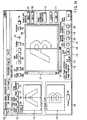
- FIG. 14 shows a display example on the personal computer monitor 101.
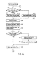
- FIGS. 15 to 17 are flow charts for explaining operation procedures and operation.
- a reference image serving as a reference for image comparison is acquired and registered (steps S11 to S23 to be described later).
- the observer selects an observation unit in the observation device 69. That is, the observer selects the macro-observation unit 72 or micro-observation unit 71 depending on the size of an observation area on a specimen or the like.
- the observer switches the optical paths by clicking a macro button 106 or micro button 107 corresponding to the macro-observation unit 72 or micro-observation unit 71 on an operation window 105 on the monitor shown in FIG. 14, thereby selecting a desired observation unit (steps S12 and S13).
- the observer selects a live image button 108a on the operation window 105 on the monitor to display the live image photographed by the TV camera 76 in an observation image display area 109 (step S14).
- the image photographed by the TV camera 76 can be displayed as a still image in the observation image display area 109 by selecting a freeze button 134.
- the observer sets a specimen serving as a sample for generating a reference image on the macro/micro motor-driven stage 75 on the selected observation unit side (step S15).
- the observer selects an illumination source suitable for the specimen by using the macro control box 96 or micro control box 95 and adjusts the brightness while looking at the live image (observation image) displayed in the observation image display area 109 (step S16).
- the observer determines whether to enlarge and observe a minute portion of the observation image (step S17). If the observer wants to enlarge the minute portion of the observation image (YES), he/she sets a magnification with a magnification change button 110. The observer then moves the pointer of the mouse 103 onto the observation image. As a consequence, a capture area with the magnification designated with the pointer is displayed on the observation image. The observer clicks a desired capture position to determine an enlargement position (step S18), and clicks a setting button 111 on the operation window 105.
- the personal computer body 82 calculates the central position of the image to be enlarged from the current stage position, the set magnification, and the position of the mouse point on the observation image.
- the personal computer body 82 then automatically moves the macro/micro motor-driven stage 75 to make the central position of the image to be enlarged coincide with the optical axis of the selected observation unit.
- a desired observation position on the specimen is set (step S19).
- the observer adjusts a zoom magnification so as to display a desired observation area of the specimen, and makes focus adjustment (step S20).
- step S17 If it is determined in step S17 that the minute portion of the observation image is not enlarged, the flow immediately advances to step S20.
- the observer then adjusts a zoom magnification so as to display a desired observation area of the specimen, and makes focus adjustment.
- step S21 The observer determines whether or not the contrast of the observation image is sufficient. If the fluorescence illumination source or specimen is low, a clear reference image cannot be generated. Hence, high-precision image comparison cannot be done. In this case, image integration processing is performed (step S22).
- the observer selects an automatic contrast button 112 on the operation window 105 to perform automatic contrast processing.
- the personal computer body 82 performs gain or offset adjustment to set an optimal luminance level for the captured image, and changes the image data.
- the personal computer body 82 displays the resultant image in the observation image display area 109 again.
- the observer adjusts the observation position, magnification, and focus of the specimen while looking at this image.
- the observer selects an integration button 113 on the operation window 105 to start image integration processing.
- the personal computer body 82 stores captured images by a set image count, adds the image data, and displays the resultant image in the observation image display area 109 again.
- the observer adjusts the number of times of integration by setting an integration count 114 on the operation window 105 in accordance with the brightness of the specimen, thus adjusting the image to facilitate observation.
- an image registration button 115 on the operation window 105 on the monitor is operated to register the displayed image as a reference image (step S23).
- the personal computer body 82 captures a video signal from the TV camera 76 in the form of a digital image through the image input board 6, and stores it as a reference image in a storage medium 10.
- the personal computer body 82 displays this image in a still image display area 116.
- the personal computer body 82 also checks photographing conditions set at this time through communication with the observation device 69 and TV camera 76, and records the conditions on a photographing condition file in the personal computer body 82. This communication is performed through the macro/micro communication cable 98 and TV camera communication cable 100.
- reference image data may be read out from the personal computer body 82 or from a recording medium in another personal computer through a communication means such as a network and registered by selecting a file read button 117 on the operation window 105.
- a communication means such as a network
- the procedure in steps S11 to S23 is not required.
- the procedure from step S11 to step S23 may be automated where possible regardless of operation by the observer.
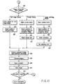
- An observation image of a specimen to be compared is acquired and compared with the reference image (steps S24 to S42 to be described later).
- the observer sets a sample specimen for comparison from which a comparison image is to be generated in placed of the sample specimen for the generation of a reference image which is set on the macro/micro motor-driven stage 75 (step S24).
- the observer selects a photographing condition button 118.
- the personal computer body 82 reads out the photographing condition file formed when the reference image was registered, and performs automatic control on the observation device 69 side through the macro/micro communication cable 98 so as to, for example, position the macro/micro motor-driven stage 75, select a zoom magnification and an illumination method, perform brightness control, and set the TV camera 76. This makes observation conditions coincide with the conditions set when the reference image was acquired.
- a live image of an observation image photographed by the TV camera 76 is then displayed in the observation image display area 109.
- the personal computer body 82 therefore performs color adjustment in the image input board so as to make the reference image and comparison image coincide with each other in terms of color reproduction.
- the personal computer body 82 performs color adjustment in the image input board to make the reference image coincide with the comparison image in terms of luminance information of red, green, and blue as color information of a feature point and background.
- the observer checks from the displayed observation image display area 109 whether or not an area of the specimen which he/she wants to observe is displayed, and adjusts the zoom magnification and focus (step S25).
- step S26 The observer checks whether or not the contrast of the image is sufficient. If the contrast of fluorescence illumination or the specimen is low, the image cannot be made clear without any processing in subsequent observation. In this case as well, image integration processing is performed (step S27).
- the observer selects the automatic contrast button automatic contrast button 112 on the operation window 105 of the monitor to perform automatic contrast processing.
- the personal computer body 82 performs gain or offset adjustment to set an optimal luminance level for observation of the captured image, and changes the image data.
- the personal computer body 82 displays the resultant image in the observation image display area 109 again.
- the observer adjusts the observation position, magnification, and focus of the specimen while looking at this image.
- the observer selects the integration button 113 on the operation window 105 to start image integration processing.
- the personal computer body 82 stores captured images by a set image count, adds the image data, and displays the resultant image in the observation image display area 109 again.
- the observer adjusts the number of times of integration by setting the integration count 114 on the operation window 105 in accordance with the brightness of the specimen, thus adjusting the image to facilitate observation. Note that the acquisition and display of an observation image in steps S24 to S27 can be automated as in the case of the acquisition of a reference image.
- the photographing conditions for a reference image are made to coincide with those for a comparison image. This makes it possible to photograph images that can be easily compared with each other.
- the processing of comparing the images is then started.
- the observer selects an image comparison mode suitable for the specimens from "split image display”, “overlap display”, and “image switching display” on the operation window on the monitor (step S28).
- an image from the TV camera 76 is displayed as a comparison image in a live image display area 119.
- the observation image display area 109 is split into two upper and lower or left and right areas, so that a reference image formed from a still image is displayed in one split area, and a comparison image formed from a moving or still image is displayed in the other split area.
- a display method for split image display is selected (step S29).
- the display methods for split image display include: “left: reference image ⁇ right: comparison image”, “left: comparison image ⁇ right: reference image”, “upper: reference image ⁇ lower: comparison image”, and “upper: comparison image ⁇ lower: reference image”. These methods can be selected by buttons 120. Note that a ruled line serving as a boundary line that splits the area can be moved with ruled line moving buttons 133.
- the observer selects a display method for split image display which is suitable for areas of specimens which are to be compared with each other.
- a vertical scroll bar 121 and horizontal scroll bar 122 are arranged for the reference image displayed in one split area of the observation image display area 109.
- the display position of the reference image is adjusted by moving the scroll bars (step S30).
- the personal computer body 82 automatically moves the macro/micro motor-driven stage 75 in accordance with the movement amounts of the scroll bars so as to make the image display position of the reference image coincide with that of the comparison image.
- a live image is displayed as a comparison image displayed in the other split area of the observation image display area 109. If the observer wants to finely adjust the position of the comparison image as needed, he/she adjusts the display position of the comparison image by moving the macro/micro motor-driven stage 75 while checking the image.
- the luminance ratio between the reference image and the comparison image is gradually changed by changing the integers n and m , one of the images can be emphasized and displayed.
- the observer selects an overlap button 123 (step S31), and adjusts the positions of the reference image and comparison image (step S32), thus eliminating the slight positional error between the reference image and the comparison image by moving the macro/micro motor-driven stage 75 while checking the overlap image.
- the observer checks the overlap image to find a mismatch.
- adjustment of a display ratio step S33
- image switching display as the third image comparison mode, two images, i.e., a reference image and comparison image, are repeatedly and alternately switched and displayed in the observation image display area at predetermined time intervals.
- the observer selects the overlap button 123 in advance (step 534 ⁇ and adjusts the positions of the reference image and comparison image (step S35), thus eliminating the slight positional error between the reference image and the comparison image.
- the observer selects an image switching display (animation) button 125 (step S36), and checks a mismatch while checking the switched images. That is, the observer recognizes a different portion by the persistence of vision by alternately switching the images. In this case, the observer sets a switching time (step S37) to observe the images upon setting a switching time suitable for comparison by operating the internal electrode 126.
- an up/down button 127, left/right button 128, and negative button 129 are arranged in the still image display area 116 to change the display method for a reference image.
- the reference image can be vertically and horizontally reversed by using the up/down button 127 and left/right button 128 so as to make the direction of the image photographed from the lower surface side coincide with the direction of the image photographed from the upper surface side.
- positive/negative reversal of an image on one side by means of the negative button 129 facilitates recognition of image comparison.
- step S38 the personal computer body 82 compares binary images of the reference image and comparison image, and colors a different portion or displays it with a mark or the like, thereby supporting image comparison by the observer. The observer then visually observes the images and compares the images 51 with each other upon referring to the automatic foreign object detection processing (step S39).
- a drawing function allows the observer to input a comment on a reference image, a comparison image, or a observation image in the image comparison mode (step S40). The observer then adds a supplementary remark.
- the observer causes an image required to be stored to be displayed in the observation image display area 109 and selects an image storage button 132, the image is stored in a desired storage medium (step S41). At this time, the personal computer body 82 also stores observation conditions for the stored image.
- the observer determines whether to continue detailed comparison observation upon changing the observation portions of the specimens (step S42). If comparison observation is to be continued, the flow returns to step S11 to repeat the above operation. If comparison observation is not to be continued, the observation is finished.
- the observer can easily compare and observe a reference image and comparison image upon making the characteristic portions of the specimens more clear by using the micro-observation unit 71, the macro-observation unit 72, various kinds of illumination devices, and the respective image comparison modes.
- the observer can observe a reference image stored in advance and a comparison image that is being photographed by the micro-observation unit 71 or macro-observation unit 72 under the same observation conditions as those in the past.
- the observer can also easily compare and observe a characteristic feature of a specimen observed in the past and a Characteristic feature of a currently observed specimen under the same conditions.
- observation conditions set when an image is stored are stored together with image data. If, for example, the observation conditions are stored in a shared storage medium, the same observation conditions as those set when image comparison was performed by using images used in the past can be automatically set in any system, thereby greatly improving the efficiency of reexamination.
- the macro/micro motor-driven stage 75 automatically moves to the observation position, and the magnification changes.
- the use of various kinds of image comparison modes facilitates comparison between a reference image and a comparison image. This allows the observer to easily find the difference between the images. In addition, this makes it possible to perform high-precision image comparison.
- an image comparison apparatus and image comparison method which can perform comparison observation of a reference image and comparison image by simple operation with high precision and efficiency, and a program for causing a computer to execute image comparison.
Landscapes
- Physics & Mathematics (AREA)
- Chemical & Material Sciences (AREA)
- Analytical Chemistry (AREA)
- General Physics & Mathematics (AREA)
- Optics & Photonics (AREA)
- Engineering & Computer Science (AREA)
- Multimedia (AREA)
- Computer Vision & Pattern Recognition (AREA)
- Image Processing (AREA)
- Microscoopes, Condenser (AREA)
- Image Analysis (AREA)
Applications Claiming Priority (3)
| Application Number | Priority Date | Filing Date | Title |
|---|---|---|---|
| JP2001041931 | 2001-02-19 | ||
| JP2001041931 | 2001-02-19 | ||
| PCT/JP2002/001364 WO2002067039A1 (fr) | 2001-02-19 | 2002-02-18 | Dispositif de comparaison d'images, procede de comparaison d'images et programme comportant une comparaison d'images informatisee |
Publications (2)
| Publication Number | Publication Date |
|---|---|
| EP1372013A1 true EP1372013A1 (de) | 2003-12-17 |
| EP1372013A4 EP1372013A4 (de) | 2009-11-11 |
Family
ID=18904304
Family Applications (1)
| Application Number | Title | Priority Date | Filing Date |
|---|---|---|---|
| EP02712419A Withdrawn EP1372013A4 (de) | 2001-02-19 | 2002-02-18 | Bildvergleichseinrichtung, bildvergleichsverfahren und programm mit auf computer ablaufendem bildvergleich |
Country Status (5)
| Country | Link |
|---|---|
| US (1) | US7050622B2 (de) |
| EP (1) | EP1372013A4 (de) |
| JP (1) | JPWO2002067039A1 (de) |
| TW (1) | TWI274289B (de) |
| WO (1) | WO2002067039A1 (de) |
Cited By (4)
| Publication number | Priority date | Publication date | Assignee | Title |
|---|---|---|---|---|
| EP1293927A2 (de) * | 2001-08-29 | 2003-03-19 | Olympus Optical Co., Ltd. | Bildvergleichsvorrichtung und -verfahren und ein Programm zum Durchführen von Vergleichen von Bildern mit dem Computer speicherndes computerlesbares Medium |
| WO2010103527A3 (en) * | 2009-03-13 | 2010-11-11 | Ramot At Tel-Aviv University Ltd. | Imaging system and method for imaging objects with reduced image blur |
| EP2328009A1 (de) * | 2008-09-26 | 2011-06-01 | Olympus Corporation | Mikroskopsystem, speichermedium mit darauf gespeichertem steuerprogramm sowie steuerverfahren dafür |
| WO2017165343A3 (en) * | 2016-03-24 | 2018-08-23 | Molecular Devices, Llc | lMAGING SYSTEM WITH ANCILLARY lMAGE DETECTOR FOR SAMPLE LOCATION |
Families Citing this family (31)
| Publication number | Priority date | Publication date | Assignee | Title |
|---|---|---|---|---|
| JP3814514B2 (ja) * | 2001-10-23 | 2006-08-30 | キヤノン株式会社 | 画像表示装置、画像処理方法及びプログラム |
| US8724865B2 (en) * | 2001-11-07 | 2014-05-13 | Medical Metrics, Inc. | Method, computer software, and system for tracking, stabilizing, and reporting motion between vertebrae |
| US7167197B2 (en) * | 2002-03-22 | 2007-01-23 | Bae Systems Controls, Inc. | Apparatus and method to evaluate an illuminated panel |
| US20050157170A1 (en) * | 2002-08-20 | 2005-07-21 | Olympus Corporation | Image comparison apparatus, image comparison method, and program to execute image comparison by computer |
| JP2005091430A (ja) * | 2003-09-12 | 2005-04-07 | Fuji Photo Film Co Ltd | 画像比較表示方法及びその装置並びに画像比較表示プログラム |
| US7693324B2 (en) * | 2004-07-13 | 2010-04-06 | International Business Machines Corporation | Optical surface inspection |
| US7391907B1 (en) * | 2004-10-01 | 2008-06-24 | Objectvideo, Inc. | Spurious object detection in a video surveillance system |
| US20060098862A1 (en) * | 2004-11-10 | 2006-05-11 | International Business Machines Corporation | Nanoscale defect image detection for semiconductors |
| WO2006080943A1 (en) * | 2005-01-24 | 2006-08-03 | Thomson Licensing | Method, apparatus and system for visual inspection of transcoded video |
| WO2007117764A2 (en) * | 2006-02-13 | 2007-10-18 | Chemimage Corporation | System and method for super resolution of a sample in a fiber array spectral translator system |
| JP2007228010A (ja) * | 2006-02-21 | 2007-09-06 | Seiko Epson Corp | 画像処理装置、コンピュータプログラム、画像出力装置および印刷画像プレビュー方法 |
| KR101310823B1 (ko) * | 2006-06-20 | 2013-09-25 | 삼성전자주식회사 | 디지털 촬영장치의 제어방법 및 이 방법을 채용한 디지털촬영장치 |
| JP5034359B2 (ja) * | 2006-08-07 | 2012-09-26 | 富士通株式会社 | 画像認証装置、画像認証方法、画像認証プログラム、記録媒体及び電子機器 |
| JP2008294981A (ja) * | 2007-05-28 | 2008-12-04 | Panasonic Corp | カメラシステム |
| JP5350611B2 (ja) * | 2007-06-28 | 2013-11-27 | シスメックス株式会社 | 表示方法および試料分析装置 |
| US7652716B2 (en) * | 2007-05-31 | 2010-01-26 | Microsoft Corporation | Computer-controlled lighting for video communication |
| JP5305719B2 (ja) * | 2007-06-07 | 2013-10-02 | オリンパス株式会社 | 顕微鏡システム |
| JP2009278373A (ja) * | 2008-05-14 | 2009-11-26 | Sharp Corp | 画像処理装置、画像形成装置及びコンピュータプログラム |
| US20100111445A1 (en) * | 2008-11-05 | 2010-05-06 | Chih-Yi Yang | Portable image-extracting device for identifying tiny images and method of the same |
| CN102542298A (zh) * | 2010-12-30 | 2012-07-04 | 富泰华工业(深圳)有限公司 | 电子装置及其图像相似度比较的方法 |
| JP2013137635A (ja) * | 2011-12-28 | 2013-07-11 | Dainippon Screen Mfg Co Ltd | 画像表示装置および画像表示方法 |
| KR20140140047A (ko) | 2012-02-27 | 2014-12-08 | 임플리시트캐어, 엘엘씨. | 360°영상 시스템 |
| US9408540B2 (en) | 2012-02-27 | 2016-08-09 | Ovio Technologies, Inc. | Rotatable imaging system |
| US10171734B2 (en) | 2012-02-27 | 2019-01-01 | Ovio Technologies, Inc. | Rotatable imaging system |
| US9060125B2 (en) | 2012-02-27 | 2015-06-16 | Implicitcare, Llc | 360° imaging system |
| JP6455829B2 (ja) * | 2013-04-01 | 2019-01-23 | キヤノン株式会社 | 画像処理装置、画像処理方法、およびプログラム |
| KR102244258B1 (ko) * | 2013-10-04 | 2021-04-27 | 삼성전자주식회사 | 디스플레이 장치 및 이를 이용한 영상표시방법 |
| JP6140255B2 (ja) * | 2015-11-13 | 2017-05-31 | 株式会社キーエンス | 画像処理装置及び画像処理方法 |
| CN108537111A (zh) * | 2018-02-26 | 2018-09-14 | 阿里巴巴集团控股有限公司 | 一种活体检测的方法、装置及设备 |
| JPWO2020148949A1 (ja) * | 2019-01-18 | 2021-12-02 | 株式会社ソニー・インタラクティブエンタテインメント | 情報処理装置および画像生成方法 |
| JP7299046B2 (ja) * | 2019-03-25 | 2023-06-27 | ソニー・オリンパスメディカルソリューションズ株式会社 | 医療用観察制御装置及び医療用観察システム |
Citations (7)
| Publication number | Priority date | Publication date | Assignee | Title |
|---|---|---|---|---|
| US4160263A (en) * | 1978-05-15 | 1979-07-03 | George R. Cogar | Dual or multiple objective video microscope for superimposing spaced images |
| US4755874A (en) * | 1987-08-31 | 1988-07-05 | Kla Instruments Corporation | Emission microscopy system |
| JPH066807A (ja) * | 1992-06-19 | 1994-01-14 | Olympus Optical Co Ltd | 画像比較装置 |
| JPH10339845A (ja) * | 1997-06-09 | 1998-12-22 | Olympus Optical Co Ltd | モニタ観察型顕微鏡 |
| WO1999041621A2 (en) * | 1998-02-13 | 1999-08-19 | Scientific Generics Limited | Circuit board assembly inspection |
| EP0999440A1 (de) * | 1998-11-06 | 2000-05-10 | Toppan Printing Co., Ltd. | Verfahren und System zum Inspektieren von Gegenstände |
| WO2000070332A1 (en) * | 1999-05-18 | 2000-11-23 | Applied Materials, Inc. | Method of and apparatus for inspection of articles by comparison with a master |
Family Cites Families (13)
| Publication number | Priority date | Publication date | Assignee | Title |
|---|---|---|---|---|
| US3916439A (en) * | 1974-03-08 | 1975-10-28 | Westinghouse Electric Corp | Inspection system employing differential imaging |
| GB2129547B (en) * | 1982-11-02 | 1986-05-21 | Cambridge Instr Ltd | Reticle inspection |
| US4589140A (en) * | 1983-03-21 | 1986-05-13 | Beltronics, Inc. | Method of and apparatus for real-time high-speed inspection of objects for identifying or recognizing known and unknown portions thereof, including defects and the like |
| US4821118A (en) * | 1986-10-09 | 1989-04-11 | Advanced Identification Systems, Inc. | Video image system for personal identification |
| US5600732A (en) * | 1994-12-08 | 1997-02-04 | Banctec, Inc. | Document image analysis method |
| US5566877A (en) * | 1995-05-01 | 1996-10-22 | Motorola Inc. | Method for inspecting a semiconductor device |
| US6381355B1 (en) * | 1997-08-19 | 2002-04-30 | The Hong Kong University Of Science And Technology | Inspection method for comparison of articles |
| JPH1196362A (ja) * | 1997-09-17 | 1999-04-09 | Fujitsu Ltd | 印影照合装置 |
| JP2000116637A (ja) * | 1998-10-12 | 2000-04-25 | Ge Yokogawa Medical Systems Ltd | 画像表示方法および装置並びに放射線透視撮影装置 |
| US6434264B1 (en) * | 1998-12-11 | 2002-08-13 | Lucent Technologies Inc. | Vision comparison inspection system |
| JP2000275594A (ja) * | 1999-03-24 | 2000-10-06 | Olympus Optical Co Ltd | 基板検査装置 |
| US6655284B1 (en) * | 1999-06-28 | 2003-12-02 | Casio Computer Co., Ltd. | Customer terminal apparatus and information distribution server |
| US6597381B1 (en) * | 1999-07-24 | 2003-07-22 | Intelligent Reasoning Systems, Inc. | User interface for automated optical inspection systems |
-
2002
- 2002-02-18 TW TW091102709A patent/TWI274289B/zh not_active IP Right Cessation
- 2002-02-18 EP EP02712419A patent/EP1372013A4/de not_active Withdrawn
- 2002-02-18 WO PCT/JP2002/001364 patent/WO2002067039A1/ja active Application Filing
- 2002-02-18 JP JP2002566706A patent/JPWO2002067039A1/ja active Pending
-
2003
- 2003-08-05 US US10/635,821 patent/US7050622B2/en not_active Expired - Lifetime
Patent Citations (7)
| Publication number | Priority date | Publication date | Assignee | Title |
|---|---|---|---|---|
| US4160263A (en) * | 1978-05-15 | 1979-07-03 | George R. Cogar | Dual or multiple objective video microscope for superimposing spaced images |
| US4755874A (en) * | 1987-08-31 | 1988-07-05 | Kla Instruments Corporation | Emission microscopy system |
| JPH066807A (ja) * | 1992-06-19 | 1994-01-14 | Olympus Optical Co Ltd | 画像比較装置 |
| JPH10339845A (ja) * | 1997-06-09 | 1998-12-22 | Olympus Optical Co Ltd | モニタ観察型顕微鏡 |
| WO1999041621A2 (en) * | 1998-02-13 | 1999-08-19 | Scientific Generics Limited | Circuit board assembly inspection |
| EP0999440A1 (de) * | 1998-11-06 | 2000-05-10 | Toppan Printing Co., Ltd. | Verfahren und System zum Inspektieren von Gegenstände |
| WO2000070332A1 (en) * | 1999-05-18 | 2000-11-23 | Applied Materials, Inc. | Method of and apparatus for inspection of articles by comparison with a master |
Non-Patent Citations (1)
| Title |
|---|
| See also references of WO02067039A1 * |
Cited By (17)
| Publication number | Priority date | Publication date | Assignee | Title |
|---|---|---|---|---|
| EP1293927A3 (de) * | 2001-08-29 | 2005-12-21 | Olympus Optical Co., Ltd. | Bildvergleichsvorrichtung und -verfahren und ein Programm zum Durchführen von Vergleichen von Bildern mit dem Computer speicherndes computerlesbares Medium |
| EP1293927A2 (de) * | 2001-08-29 | 2003-03-19 | Olympus Optical Co., Ltd. | Bildvergleichsvorrichtung und -verfahren und ein Programm zum Durchführen von Vergleichen von Bildern mit dem Computer speicherndes computerlesbares Medium |
| US8339702B2 (en) | 2008-09-26 | 2012-12-25 | Olympus Corporation | Microscope system, storage medium storing control program, and control method |
| EP2328009A1 (de) * | 2008-09-26 | 2011-06-01 | Olympus Corporation | Mikroskopsystem, speichermedium mit darauf gespeichertem steuerprogramm sowie steuerverfahren dafür |
| EP2328009A4 (de) * | 2008-09-26 | 2012-02-29 | Olympus Corp | Mikroskopsystem, speichermedium mit darauf gespeichertem steuerprogramm sowie steuerverfahren dafür |
| US8699129B2 (en) | 2008-09-26 | 2014-04-15 | Olympus Corporation | Microscope system, storage medium storing control program, and control method |
| CN102422200B (zh) * | 2009-03-13 | 2015-07-08 | 特拉维夫大学拉玛特有限公司 | 以减小的像模糊对物进行成像的成像系统和方法 |
| CN102422200A (zh) * | 2009-03-13 | 2012-04-18 | 特拉维夫大学拉玛特有限公司 | 以减小的像模糊对物进行成像的成像系统和方法 |
| WO2010103527A3 (en) * | 2009-03-13 | 2010-11-11 | Ramot At Tel-Aviv University Ltd. | Imaging system and method for imaging objects with reduced image blur |
| US9405119B2 (en) | 2009-03-13 | 2016-08-02 | Ramot At Tel-Aviv University Ltd. | Imaging system and method for imaging objects with reduced image blur |
| US9953402B2 (en) | 2009-03-13 | 2018-04-24 | Ramot At Tel-Aviv University Ltd. | Imaging system and method for imaging objects with reduced image blur |
| US10311555B2 (en) | 2009-03-13 | 2019-06-04 | Ramot At Tel-Aviv University Ltd. | Imaging system and method for imaging objects with reduced image blur |
| EP2406682B1 (de) * | 2009-03-13 | 2019-11-27 | Ramot at Tel-Aviv University Ltd | Abbildungssystem und abbildungsmethode mit weniger unschärfe |
| US10949954B2 (en) | 2009-03-13 | 2021-03-16 | Ramot At Tel-Aviv University Ltd. | Imaging system and method for imaging objects with reduced image blur |
| US11721002B2 (en) | 2009-03-13 | 2023-08-08 | Ramot At Tel-Aviv University Ltd. | Imaging system and method for imaging objects with reduced image blur |
| WO2017165343A3 (en) * | 2016-03-24 | 2018-08-23 | Molecular Devices, Llc | lMAGING SYSTEM WITH ANCILLARY lMAGE DETECTOR FOR SAMPLE LOCATION |
| US10551608B2 (en) | 2016-03-24 | 2020-02-04 | Molecular Devices, Llc | Imaging system with ancillary image detector for sample location |
Also Published As
| Publication number | Publication date |
|---|---|
| EP1372013A4 (de) | 2009-11-11 |
| JPWO2002067039A1 (ja) | 2004-06-24 |
| WO2002067039A1 (fr) | 2002-08-29 |
| US20040037468A1 (en) | 2004-02-26 |
| TWI274289B (en) | 2007-02-21 |
| US7050622B2 (en) | 2006-05-23 |
Similar Documents
| Publication | Publication Date | Title |
|---|---|---|
| US7050622B2 (en) | Image comparison apparatus, image comparison method, and program for causing computer to execute image comparison | |
| US11594024B2 (en) | Augmented reality microscope for pathology | |
| JP4970869B2 (ja) | 観察装置および観察方法 | |
| EP2910993B1 (de) | Digitalmikroskop | |
| JP2019532352A (ja) | 組織標本の組織学的検査のためのシステム | |
| EP1797816A2 (de) | Vorrichtung und Verfahren zur Verarbeitung eines Augenhintergrund-Bildes | |
| JP2008052227A (ja) | 観察装置 | |
| JP2014078008A (ja) | レーザー顕微解剖領域の画定方法及び関連するレーザー顕微解剖システム | |
| EP1293927A2 (de) | Bildvergleichsvorrichtung und -verfahren und ein Programm zum Durchführen von Vergleichen von Bildern mit dem Computer speicherndes computerlesbares Medium | |
| US11112952B2 (en) | Interface for display of multi-layer images in digital microscopy | |
| EP1768065A1 (de) | Multitemporale Mehrpunkt-Bildaufnahme mit Kontrolle der Beleuchtungsdosis | |
| US11906724B2 (en) | Apparatuses, systems and methods for generating color video with a monochrome sensor | |
| JP2024019639A (ja) | 顕微鏡システム、プログラム、及び、投影画像生成方法 | |
| JP2013044967A (ja) | 顕微鏡システム、標本画像生成方法及びプログラム | |
| US20050157170A1 (en) | Image comparison apparatus, image comparison method, and program to execute image comparison by computer | |
| JP2007017930A (ja) | 顕微鏡装置 | |
| JP2011027725A (ja) | 医療診断支援装置、バーチャル顕微鏡システムおよび標本支持部材 | |
| JP2004078690A (ja) | 画像比較装置、画像比較方法および画像比較をコンピュータにて実行させるためのプログラム | |
| JP4576112B2 (ja) | 共焦点レーザ顕微鏡 | |
| JP4633322B2 (ja) | 画像比較装置、画像比較方法および画像比較をコンピュータにて実行させるためのプログラム | |
| US8411357B2 (en) | Motor-operated microscope system and software for controlling motor-operated microscopes | |
| JPH10333053A (ja) | 焦点深度伸長装置 | |
| JP2004309768A (ja) | 顕微鏡システム | |
| EP1549072A1 (de) | Bildvergleichseinrichtung, bildvergleichsverfahren und programm, das bewirkt, dass ein computer einen bildvergleich ausf hrt | |
| JP4632479B2 (ja) | 顕微鏡装置 |
Legal Events
| Date | Code | Title | Description |
|---|---|---|---|
| PUAI | Public reference made under article 153(3) epc to a published international application that has entered the european phase |
Free format text: ORIGINAL CODE: 0009012 |
|
| 17P | Request for examination filed |
Effective date: 20030910 |
|
| AK | Designated contracting states |
Kind code of ref document: A1 Designated state(s): AT BE CH CY DE DK ES FI FR GB GR IE IT LI LU MC NL PT SE TR |
|
| AX | Request for extension of the european patent |
Extension state: AL LT LV MK RO SI |
|
| RAP1 | Party data changed (applicant data changed or rights of an application transferred) |
Owner name: OLYMPUS CORPORATION |
|
| RTI1 | Title (correction) |
Free format text: IMAGE COMPARISON APPARATUS, IMAGE COMPARISON METHOD, AND PROGRAM CAUSING COMPUTER TO EXECUTE IMAGE COMPARISON |
|
| RBV | Designated contracting states (corrected) |
Designated state(s): DE GB |
|
| A4 | Supplementary search report drawn up and despatched |
Effective date: 20090911 |
|
| 17Q | First examination report despatched |
Effective date: 20091217 |
|
| R17C | First examination report despatched (corrected) |
Effective date: 20091217 |
|
| STAA | Information on the status of an ep patent application or granted ep patent |
Free format text: STATUS: THE APPLICATION IS DEEMED TO BE WITHDRAWN |
|
| 18D | Application deemed to be withdrawn |
Effective date: 20111124 |