EP1369945A2 - Brenstoffzellen-System - Google Patents
Brenstoffzellen-System Download PDFInfo
- Publication number
- EP1369945A2 EP1369945A2 EP03008589A EP03008589A EP1369945A2 EP 1369945 A2 EP1369945 A2 EP 1369945A2 EP 03008589 A EP03008589 A EP 03008589A EP 03008589 A EP03008589 A EP 03008589A EP 1369945 A2 EP1369945 A2 EP 1369945A2
- Authority
- EP
- European Patent Office
- Prior art keywords
- cooling water
- fuel cell
- supply
- gas
- humidifying
- Prior art date
- Legal status (The legal status is an assumption and is not a legal conclusion. Google has not performed a legal analysis and makes no representation as to the accuracy of the status listed.)
- Granted
Links
Images


Classifications
-
- H—ELECTRICITY
- H01—ELECTRIC ELEMENTS
- H01M—PROCESSES OR MEANS, e.g. BATTERIES, FOR THE DIRECT CONVERSION OF CHEMICAL ENERGY INTO ELECTRICAL ENERGY
- H01M8/00—Fuel cells; Manufacture thereof
- H01M8/04—Auxiliary arrangements, e.g. for control of pressure or for circulation of fluids
- H01M8/04082—Arrangements for control of reactant parameters, e.g. pressure or concentration
- H01M8/04089—Arrangements for control of reactant parameters, e.g. pressure or concentration of gaseous reactants
- H01M8/04119—Arrangements for control of reactant parameters, e.g. pressure or concentration of gaseous reactants with simultaneous supply or evacuation of electrolyte; Humidifying or dehumidifying
- H01M8/04156—Arrangements for control of reactant parameters, e.g. pressure or concentration of gaseous reactants with simultaneous supply or evacuation of electrolyte; Humidifying or dehumidifying with product water removal
-
- H—ELECTRICITY
- H01—ELECTRIC ELEMENTS
- H01M—PROCESSES OR MEANS, e.g. BATTERIES, FOR THE DIRECT CONVERSION OF CHEMICAL ENERGY INTO ELECTRICAL ENERGY
- H01M8/00—Fuel cells; Manufacture thereof
- H01M8/04—Auxiliary arrangements, e.g. for control of pressure or for circulation of fluids
-
- H—ELECTRICITY
- H01—ELECTRIC ELEMENTS
- H01M—PROCESSES OR MEANS, e.g. BATTERIES, FOR THE DIRECT CONVERSION OF CHEMICAL ENERGY INTO ELECTRICAL ENERGY
- H01M8/00—Fuel cells; Manufacture thereof
- H01M8/04—Auxiliary arrangements, e.g. for control of pressure or for circulation of fluids
- H01M8/04007—Auxiliary arrangements, e.g. for control of pressure or for circulation of fluids related to heat exchange
- H01M8/04029—Heat exchange using liquids
-
- H—ELECTRICITY
- H01—ELECTRIC ELEMENTS
- H01M—PROCESSES OR MEANS, e.g. BATTERIES, FOR THE DIRECT CONVERSION OF CHEMICAL ENERGY INTO ELECTRICAL ENERGY
- H01M8/00—Fuel cells; Manufacture thereof
- H01M8/04—Auxiliary arrangements, e.g. for control of pressure or for circulation of fluids
- H01M8/04082—Arrangements for control of reactant parameters, e.g. pressure or concentration
- H01M8/04089—Arrangements for control of reactant parameters, e.g. pressure or concentration of gaseous reactants
- H01M8/04119—Arrangements for control of reactant parameters, e.g. pressure or concentration of gaseous reactants with simultaneous supply or evacuation of electrolyte; Humidifying or dehumidifying
- H01M8/04126—Humidifying
- H01M8/04134—Humidifying by coolants
-
- H—ELECTRICITY
- H01—ELECTRIC ELEMENTS
- H01M—PROCESSES OR MEANS, e.g. BATTERIES, FOR THE DIRECT CONVERSION OF CHEMICAL ENERGY INTO ELECTRICAL ENERGY
- H01M8/00—Fuel cells; Manufacture thereof
- H01M8/04—Auxiliary arrangements, e.g. for control of pressure or for circulation of fluids
- H01M8/04082—Arrangements for control of reactant parameters, e.g. pressure or concentration
- H01M8/04089—Arrangements for control of reactant parameters, e.g. pressure or concentration of gaseous reactants
- H01M8/04119—Arrangements for control of reactant parameters, e.g. pressure or concentration of gaseous reactants with simultaneous supply or evacuation of electrolyte; Humidifying or dehumidifying
- H01M8/04126—Humidifying
- H01M8/04141—Humidifying by water containing exhaust gases
-
- H—ELECTRICITY
- H01—ELECTRIC ELEMENTS
- H01M—PROCESSES OR MEANS, e.g. BATTERIES, FOR THE DIRECT CONVERSION OF CHEMICAL ENERGY INTO ELECTRICAL ENERGY
- H01M8/00—Fuel cells; Manufacture thereof
- H01M8/06—Combination of fuel cells with means for production of reactants or for treatment of residues
- H01M8/0662—Treatment of gaseous reactants or gaseous residues, e.g. cleaning
-
- Y—GENERAL TAGGING OF NEW TECHNOLOGICAL DEVELOPMENTS; GENERAL TAGGING OF CROSS-SECTIONAL TECHNOLOGIES SPANNING OVER SEVERAL SECTIONS OF THE IPC; TECHNICAL SUBJECTS COVERED BY FORMER USPC CROSS-REFERENCE ART COLLECTIONS [XRACs] AND DIGESTS
- Y02—TECHNOLOGIES OR APPLICATIONS FOR MITIGATION OR ADAPTATION AGAINST CLIMATE CHANGE
- Y02E—REDUCTION OF GREENHOUSE GAS [GHG] EMISSIONS, RELATED TO ENERGY GENERATION, TRANSMISSION OR DISTRIBUTION
- Y02E60/00—Enabling technologies; Technologies with a potential or indirect contribution to GHG emissions mitigation
- Y02E60/30—Hydrogen technology
- Y02E60/50—Fuel cells
Definitions
- the present invention relates to a fuel cell system which uses a fuel cell for power generation and a supply of heat.
- a hydrogen-rich gas supplied as fuel gas and air supplied as oxidizing gas are allowed to react to each other, thereby generating electricity and heat within the fuel cell.
- the fuel gas and oxidizing gas are supplied to the fuel cell after respectively humidified by a humidifying means.
- a humidifying means for the fuel gas and oxidizing gas is a bubbler which performs humidification by letting the fuel gas and oxidizing gas pass through hot water heated by a heater (see Japanese Patent Publication Kokai No. 7-288134).
- This fuel cell system suffers from a decline in energy efficiency because the bubbler consumes energy for heating water.
- Another known humidifier is such that moisture (water vapor) contained in exhaust air (off gas) discharged from the air pole side of the fuel cell is transferred to air to be supplied to the air pole side of the fuel cell through a vapor transmitting film, thereby humidifying the supply air (see Japanese Patent Publication Kokai No. 6-132038).
- This humidifier is designed to carry out humidification by use of exhaust air of high temperature, thereby saving energy required for the humidification.
- This humidifier has revealed such a disadvantage that the gas to be humidified (which is, herein, the supply air to be humidified) cannot be humidified to a dew point temperature higher than that of the humidifying gas (which is, herein, the exhaust gas serving as a moisture supply source).
- the gas is humidified to a high dew point temperature, vapor transmitting films having large film area become necessary, leading to an increase in the scale of the humidifier. Therefore, downsizing of the fuel cell system becomes difficult.
- a primary object of the invention is to provide a fuel cell system obtaining improved energy efficiency for the overall system by reducing the energy required for humidification of gas to be supplied to the fuel cell; having compact size; and performing stable system operation.
- a fuel cell system comprising a fuel cell for generating electricity by use of fuel gas and oxidizing gas, a first humidifying portion and second humidifying portion which sequentially humidify at least one of supply fuel gas and supply oxidizing gas, the supply fuel gas being fuel gas to be supplied to the fuel cell, the supply oxidizing gas being oxidizing gas to be supplied to the fuel cell, wherein the first humidifying portion performs the humidification by use of moisture contained in at least one of exhaust fuel gas and exhaust oxidizing gas, the exhaust fuel gas being fuel gas discharged from the fuel cell, the exhaust oxidizing gas being oxidizing gas discharged from the fuel cell, and the second humidifying portion performs the humidification by use of hot water.
- the supply fuel gas or supply oxidizing gas which has been pre-humidified in the first humidifying portion by use of the exhaust fuel gas or the exhaust oxidizing gas, further undergoes humidification carried out in the second humidifying portion by use of hot water.
- the energy (particularly, the heat energy) and moisture consumed by the humidification in the second humidifying portion can be reduced.
- the first humidifying portion carries out humidification making use of the exhaust fuel gas or exhaust oxidizing gas discharged from the fuel cell, the energy required for the humidification in the first humidifying portion can be reduced. Therefore, with the above arrangement, the energy efficiency of the overall fuel cell system can be improved.
- the moisture required in the second humidifying portion can be reduced, the amount of the moisture supplied to the second humidifying portion can be reduced, so that the temperature change in the second humidifying portion can be restrained. Therefore, the humidity in the second humidifying portion can be made stable and the system operation can perform stably. Even if the supply fuel gas or supply oxidizing gas humidified to a high dew point temperature is supplied, stepwise humidification can be effectively performed by the first and second humidifying portions, so that the fuel cell system can be downsized.
- the fuel cell system may further comprise a cooling system for allowing cooling water to flow in the fuel cell and said hot water may be the flowing cooling water.
- the supply fuel gas or supply oxidizing gas is heated by the second humidifying portion, utilizing the cooling water used for cooling the fuel cell and having a temperature of 70 to 75°C. Therefore, there is no need to heat water for the humidification in the second humidifying portion in like the case utilizing a bubbler or the like, and accordingly, the energy required for the humidification in the second humidifying portion can be reduced. Additionally, since the cooling water is maintained at a substantially stable temperature, stable, highly efficient humidification can be performed in the second humidifying portion.
- the amount of moisture consumed for the humidification in the second humidifying portion can be reduced, so that the amount of the cooling water consumed in the second humidifying portion can be reduced. Therefore, the amount of the moisture supplied with the cooling water system can be reduced. As a result, the humidity in the second humidifying portion and the temperature of the fuel cell can be made stable, so the system operation can perform stably.
- the fuel cell system may further comprise a heat-storage portion for storing at least one of the heat which has been recovered from the fuel cell by the cooling water.
- the heat-storage portion may have a hot water reserve tank in which hot water heated by a heat exchange between the cooling water is stored.
- the first humidifying portion is positioned in the upstream of the second humidifying portion, so that the heat and moisture deprived from the cooling water during the humidification in the second humidifying portion can be reduced.
- This makes it possible not only to recover a greater amount of heat from the cooling water but also to achieve the easy control of heat exchange between the cooling water and the water stored in the hot water reserve tank. Therefore, for example, in such a case that the heat-storage portion has the hot water reserve tank, it is possible to increase the temperature of the hot water stored in the hot water reserve tank by utilizing the recovered heat.
- the hot water of high temperature stored in the hot water reserve tank has a wide range of applications so that the usefulness of the recovered heat can be increased.
- the first humidifying portion may have flow paths for at least one of the supply fuel gas and the supply oxidizing gas and flow paths for at least one of the exhaust fuel gas and the exhaust oxidizing gas, each supply gas flow path and each exhaust gas flow path being in contact with each other with a moisture transmitting film for selectively transmitting moisture being interposed therebetween.
- the first humidifying portion may be formed by laminating a plurality of flow path plates, each of the flow path plates having the flow path for at least one of the supply fuel gas and the supply oxidizing gas on a first main surface and the flow path for at least one of the exhaust fuel gas and the exhaust oxidizing gas on a second main surface, the plural flow path plates being laminated such that each supply gas flow path is in contact with each exhaust gas flow path with the moisture transmitting film interposed therebetween.
- the first humidifying portion can carry out, in one process and with a simple structure, recovery of the moisture of the exhaust fuel gas or exhaust oxidizing gas discharged from the fuel cell and addition of the moisture to the supply fuel gas or supply oxidizing gas. This leads to simplification of the system and reduction of cost.
- the second humidifying portion may be formed such that each of the flow paths for at least one of the supply fuel gas and the supply oxidizing gas is in contact with each of paths for the cooling water with a moisture transmitting film for selectively transmitting moisture interposed therebetween.
- the second humidifying portion may be formed by laminating a plurality of flow path plates, each of the flow path plates having the flow path for at least one of the supply fuel gas and the supply oxidizing gas on a first main surface and the flow path for the cooling water on a second main surface, the plural flow path plates being laminated such that each supply gas flow path is in contact with each cooling water flow path with the moisture transmitting film interposed therebetween.
- the moisture of the cooling water can be transmitted to the supply fuel gas or supply oxidizing gas with a simple structure, utilizing the cooling water. This leads not only to an improvement in the energy efficiency of the system but also to simplification of the system and reduction of cost.
- the fuel cell system may have a humidifying unit wherein the first humidifying portion is adjacent to and integral with the second humidifying portion.
- the humidifying unit may be formed by laminating the plural flow path plates with the moisture transmitting film for selectively transmitting moisture being interposed between every two plates, each flow path plate having, on a first main surface, the flow path for at least one of the exhaust fuel gas and the exhaust oxidizing gas in the region of the first humidifying portion and the flow path for the cooling water in the region of the second humidifying portion and having, on a second main surface, the flow path for at least one of the supply fuel gas and the supply oxidizing gas, the supply gas flow path continuously extending throughout the first and second humidifying portions.
- the first humidifying portion of the humidifying unit may be formed by laminating a plurality of first flow path plates with the moisture transmitting film for selectively transmitting moisture interposed between every two plates, each first flow path plate having the flow path for at least one of the exhaust fuel gas and the exhaust oxidizing gas on a first main surface and the flow path for at least one of the supply fuel gas and the supply oxidizing gas on a second main surface, whereas the second humidifying portion of the humidifying unit may be formed by laminating a plurality of second flow path plates with the moisture transmitting film for selectively transmitting moisture interposed between every two plates, each second flow path plate having the flow path for the cooling water on a first main surface and the flow path for at least one of the supply fuel gas and the supply oxidizing gas on a second main surface, and the first and second humidifying portions are laminated to constitute the humidifying unit.
- the supply fuel gas or the supply oxidizing gas may be fed from the first humidifying portion to the second humidifying portion without use of a pipeline. This brings about not only a reduction in the size and cost of the fuel cell system but also prevention of energy loss in the pipelines etc., which leads to improved energy efficiency.
- the humidifying unit may be adjacent to and integral with the fuel cell, or alternatively, the second humidifying portion may be adjacent to and integral with the fuel cell.
- the supply fuel gas or the supply oxidizing gas can be supplied from the humidifying unit to the fuel cell or from the second humidifying portion to the fuel cell without use of a pipeline.
- This brings about not only a reduction in the size and cost of the fuel cell system but also prevention of energy loss in the pipelines etc., which leads to improved energy efficiency.
- the need for a pipeline between the second humidifying portion and the fuel cell is obviated, the moisture of condensed dew caused by heat dissipation in the pipeline is prevented from entering the fuel cell. As a result, the fuel cell system can be more stably operated.
- the fuel cell system may further comprise a humidity detector for detecting the humidity of at least one of the supply fuel gas and the supply oxidizing gas to be supplied from the second humidifying portion to the fuel cell and a control unit for controlling the humidity of the supply gas based on the humidity of the supply gas which has been detected by the humidity detector.
- the control unit may control the humidity of the supply gas by controlling the temperature or flow rate of the cooling water to be supplied to the second humidifying portion.
- the cooling system may have a cooling water path for allowing the cooling water to flow to the second humidifying portion and a cooling water bypass path connected to the cooling water path for bypassing the second humidifying portion, while the control unit controls the humidity of the supply gas by controlling the flow rate of the cooling water to be supplied to the second humidifying portion through the cooling water path and the flow rate of the cooling water to be supplied to the cooling water bypass path.
- the fuel cell system may further comprise a cooling water temperature detector for detecting the temperature of the cooling water to be supplied to the second humidifying portion and a control unit for controlling the humidity of at least one of the supply fuel gas and the supply oxidizing gas based on the temperature of the cooling water which has been detected by the cooling water temperature detector.
- the control unit may control the temperature or flow rate of the cooling water to be supplied to the second humidifying portion.
- the cooling system may have a cooling water path for allowing the cooling water to flow to the second humidifying portion and a cooling water bypass path connected to the cooling water path for bypassing the second humidifying portion, while the control unit may control the humidity of the supply gas by controlling the flow rate of the cooling water to be supplied to the second humidifying portion through the cooling water path and the flow rate of the cooling water to be supplied to the cooling water bypass path.
- the fuel cell system may further comprise a gas flow rate detector for detecting the flow rate of at least one of the supply fuel gas and the supply oxidizing gas to be supplied to the fuel cell and a control unit for controlling the humidity of the supply gas based on the flow rate of the supply gas which has been detected by the gas flow rate detector.
- the control unit may control the humidity of the supply gas by controlling the temperature or flow rate of the cooling water to be supplied to the second humidifying portion.
- the cooling system may have a cooling water path for allowing the cooling water to flow to the second humidifying portion and a cooling water bypass path connected to the cooling water path for bypassing the second humidifying portion, whereas the control unit may control the humidity of the supply gas by controlling the flow rate of the cooling water to be supplied to the second humidifying portion through the cooling water path and the flow rate of the cooling water to be supplied to the cooling water bypass path.
- the fuel cell system may further comprises an electricity generation detector for detecting the amount of electricity generated by the fuel cell and a control unit for controlling the humidity of at least one of the supply fuel gas and the supply oxidizing gas based on the amount of generated electricity which has been detected by the electricity generation detector.
- the control unit may control the humidity of the supply gas by controlling the temperature or flow rate of the cooling water to be supplied to the second humidifying portion.
- the cooling system may have a cooling water path for allowing the cooling water to flow to the second humidifying portion and a cooling water bypass path connected to the cooling water path for bypassing the second humidifying portion, whereas the control unit may control the humidity of the supply gas by controlling the flow rate of the cooling water to be supplied to the second humidifying portion through the cooling water path and the flow rate of the cooling water to be supplied to the cooling water bypass path.
- the humidity of the supply fuel gas or the supply oxidizing gas can be optimized, which entails an improvement in the stability and energy efficiency of the fuel cell system.
- the cooling water flow rate is controlled by the provision of the cooling water bypass path
- the flow rate of the cooling water to be fed to the fuel cell and the flow rate of the cooling water to be fed to the second humidifying portion can be controlled independently , so that the cooling water can be fed to the second humidifying portion at the optimum flow rate for the humidification of the supply fuel gas or the supply oxidizing gas, while the other cooling water can be fed to the cooling water bypass path and flow without by way of the second humidifying portion.
- the waste of moisture and heat energy of the cooling water in the second humidifying portion can be restrained, so that the consumption of the moisture and heat energy of the cooling water in the second humidifying portion can be reduced. Therefore, it is possible not only to get efficiently the supply fuel gas or the supply oxidizing gas which is humidified suitably, but also to achieve the efficient and stable cooling of the fuel cell, which is an intrinsic function of the cooling water, so that the operating temperature of the fuel cell can be adjusted to the optimum values and the heat of the cooling water can be recovered efficiently. Accordingly, the stability and energy efficiency of the fuel cell system can be further improved.
- FIG 1 diagrammatically shows a structure of a fuel cell cogeneration system (hereinafter simply referred to as "fuel cell system”) according to a first embodiment of the invention.
- the fuel cell system of the present embodiment includes, as main components, an air supply unit 40, a pre-humidifying unit 22, a humidifying unit 21a, a fuel cell 11, a fuel supply unit 41, a fuel processing unit 42, a humidifying unit 21b, a cooling water heat radiator 13, a cooling water tank 14, and a cooling water pump 12.
- Air supplied from the air supply unit 40 to the pre-humidifying unit 22 through an air path 1 is humidified by the pre-humidifying unit 22 as described later.
- the humidified air is supplied to the humidifying unit 21a through an air path 2 and further humidified by the humidifying unit 21a.
- conventional humidifiers may be used, examples of which include a bubbler for performing humidification by letting air pass through hot water heated by a heater and a humidifier which humidifies the air by directly spraying water vapor to air with an injector.
- the air humidified by the humidifying unit 21a is supplied to the air pole side of the fuel cell 11 through an air path 3 as an oxidizing gas.
- a material e.g., a gas such as city gas, propane gas, methane gas, natural gas, and alcohol, which contains at least hydrogen and carbon as major component
- a material e.g., a gas such as city gas, propane gas, methane gas, natural gas, and alcohol, which contains at least hydrogen and carbon as major component
- a reformer in which a reformed gas containing hydrogen is generated by reforming reaction, a sifter in which a carbon monoxide contained in the reformed gas is reduced by sifting reaction, and a purifier in which a carbon monoxide contained in the reformed gas passed through the sifter is further reduced by selective oxidation are used as the fuel processing unit 42.
- the material which has been supplied is heated in an atmosphere of water vapor, thereby generating hydrogen-rich gas.
- the hydrogen-rich gas is fed to the humidifying unit 21b through a fuel gas path 9a and humidified by the humidifying unit 21b.
- the humidifying unit 21b the humidifiers listed earlier as examples of the humidifying unit 21a may be used.
- the humidified hydrogen-rich gas is fed to the fuel pole side of the fuel cell 11 as a fuel gas for the fuel cell llthrough a fuel gas path 9b.
- the air which has been fed to the air pole side reacts to the hydrogen-rich gas (hereinafter referred to as "fuel gas") which has been fed to the fuel pole side, causing power generation, so that electricity and heat are generated.
- fuel gas hydrogen-rich gas
- the pre-humidifying unit 22 Of the air fed to the fuel cell 11, a portion which has not been utilized in the reaction is supplied to the pre-humidifying unit 22 through an exhaust air path 4.
- moisture contained in the exhaust air which has been fed to the pre-humidifying unit 22 is utilized to humidify air to be supplied to the fuel cell 11 as oxidizing gas.
- the exhaust air which has passed through the pre-humidifying unit 22 is exhausted.
- the fuel gas which has not been utilized in the reaction occurring in the fuel cell 11 is exhausted.
- cooling water stored in the cooling water tank 14 is pressurized and supplied to the fuel cell 11 through a cooling water path 7 by the cooling water pump 12.
- the cooling water of the cooling water tank 14 is kept at a temperature of about 70°C.
- the heat of the fuel cell 11 is removed by the supplied cooling water.
- the cooling water which has recovered the heat and had a temperature of about 75°C is again brought back to the cooling water tank 14 through a cooling water flow path 6.
- the cooling water heat radiator 13 is provided in the cooling water flow path 6, which dissipates the heat of the cooling water. Such heat dissipation cools the cooling water to about 70°C again.
- the fuel cell system is designed to allow such cooling water circulation and the cooling water is stably kept at a specified temperature, so that the fuel cell 11 can be maintained at a specified temperature.
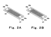
- Figures 2 and 3 are views illustrating the structure of the pre-humidifying unit 22 of the fuel cell system shown in Figure 1.
- Figure 2 is an oblique perspective view of flow path plates which constitute the pre-humidifying unit
- Figure 2A shows a surface of the flow path plate
- Figure 2B shows a rear face of the flow path plate.
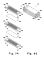
- Figure 3 shows a structure of the pre-humidifying unit 22
- Figure 3A is an exploded diagrammatical perspective view
- Figure 3B is a perspective view of the pre-humidifying unit22 constructed by lamination of the flow path plates shown in Figure 2A, 2B.
- the pre-humidifying unit 22 is constituted by a plurality of flow path plates 27 which are laminated with a moisture transmitting film 23 between every two plates.
- Each flow path plate 27 includes a flow path 24 for air to be fed to the fuel cell 11 (hereinafter referred to as “supply air flow path”) and a flow path 25 for air discharged from the fuel cell 11 (hereinafter referred to as "exhaust air flow path”), the supply air flow path 24 being formed on the surface of a base material whereas the exhaust air flow path 25 is formed on the rear face of the base material.
- the moisture transmitting films 23, transmitting moisture selectively include, for example, a proton-conductive, high-polymer electrolyte membrane such as Naphyon-base films.
- the supply air flow path 24 and exhaust air flow path 25 of each flow path plate 27 are formed by making a plurality of grooves in a stripe pattern or grooves bended in parallel with each other on the surface and rear face of a plate base material.
- manifold holes 28a, 28b which serve as a path for the supply air
- manifold holes 29a, 29b which serve as a path for the exhaust air are formed.
- a supply air introducing flow path 28a' constituted by the communicating manifold holes 28a, a supply air withdrawing flow path 28b' constituted by the communicating manifold holes 28b, an exhaust air introducing flow path 29a' constituted by the communicating manifold holes 29a, and an exhaust air withdrawing flow path 29b' constituted by the communicating manifold holes 29b are formed in the laminate.
- the supply air introducing flow path 28a' constituted by the communicating manifold holes 28a is connected to the air path 1, whereas the supply air withdrawing flow path 28b' constituted by the communicating manifold holes 28b is connected to the air path 2.
- the air supplied from the air path 1 to the flow path plates 27 of the pre-humidifying unit 22 i.e., the supply air
- the exhaust air introducing flow path 29a' constituted by the communicating manifold holes 29a is connected to the exhaust air path 4 whereas the exhaust air withdrawing flow path 29b' constituted by the communicating manifold holes 29b is connected to the exhaust air path 5.
- the air supplied from the exhaust air path 4 to the flow path plates 27 of the pre-humidifying unit 22 i.e., the exhaust air
- opposite flows of air are formed on the surfaces and rear faces of the flow path plates 27.
- the plural flow path plates 27 having the above structure are laminated with a moisture transmitting film 23 between every two flow path plates 27 in the pre-humidifying unit 22, the supply air flowing through the supply air flow path 24 formed on the surface of a flow path plate 27 is in contact with the exhaust air flowing through the exhaust air flow path 25 formed on the rear face of another flow path plate 27, through a moisture transmitting film 23.
- the exhaust air discharged from the fuel cell 11 contains a larger amount of moisture than the supply air, the moisture of the exhaust air is shifted to the supply air by way of the moisture transmitting film 23 within the pre-humidifying unit 22 of the above structure.
- the transfer of the moisture is efficiently carried out, particularly for the reason that the supply air and the exhaust air, which form opposite flows, are in contact with each other. In this way, the supply air is humidified by water vapor recovered from the exhaust air in the pre-humidifying unit 22.
- the supply air which has been thus humidified by the pre-humidifying unit 22 is fed to the humidifying unit 21a via the air path 2. Since the air fed to the unit 21a is humidified by the pre-humidifying unit 22 beforehand as described earlier, humidification may be carried out to a less degree in the humidifying unit 21a, compared to the conventional case where humidification is done only by the humidifying unit 21a. For this reason, heat energy and moisture required for the humidifying unit 21a can be reduced. In the fuel cell system of the present embodiment capable of reducing energy consumption in the humidifying unit 21a by carrying out humidification of the supply air beforehand with the pre-humidifying unit 22, the energy efficiency of the overall system can be improved.
- the moisture consumed in the humidifying unit 21a can be reduced, the amount moisture supplied to the humidifying unit 21a can be reduced. As a result, temperature change caused by supplied moisture can be restrained, so that the stable amount of humidification can be achieved in the humidifying unit 21a.
- a pre-humidifying unit may be provided in the upstream of the humidifying unit 21b for stepwise humidification of the fuel gas, like the above-described case of the humidification in the air side.
- the exhaust fuel gas discharged from the fuel cell 11 is fed to the pre-humidifying unit and, in this unit, the moisture of the exhaust fuel gas is shifted to the supply fuel gas, thereby performing humidification of the supply fuel gas, and the heat energy of the exhaust fuel gas is sifted to the supply fuel gas, thereby heating the supply gas.
- This pre-humidifying unit has a structure, like the pre-humidifying unit 22 described in the case of the humidification in the air side, in which a plurality of flow path plates are laminated with a moisture transmitting film between every two plates. In this case, a supply fuel gas flow path is formed on the surface of each flow path plate while an exhaust fuel gas flow path being formed on the rear face of the same.
- the pre-humidifying unit for humidifying the supply gas using the exhaust gas discharged from the fuel cell 11 may be provided on both the air side and the fuel side, or alternatively, on either the air side or the fuel side.
- the moisture content of the exhaust air from the fuel cell 11 is higher than that of the exhaust fuel gas, and the shift of only moisture through the moisture transmitting film can be effected more effectively in the case of the exhaust air than in the case of the exhaust fuel gas.
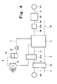
- FIG. 4 diagrammatically illustrates a structure of a fuel cell system according to a second embodiment of the invention.
- the fuel cell system of the present embodiment has the same structure as in the fuel cell system of the first embodiment, except that a humidifying unit 21a' for humidifying the supply air with circulating cooling water used for cooling the fuel cell 11 is provided in place of the humidifying unit 21a constituted by a conventional humidifier such as bubblers.
- a humidifying unit 21a' for humidifying the supply air with circulating cooling water used for cooling the fuel cell 11 is provided in place of the humidifying unit 21a constituted by a conventional humidifier such as bubblers.
- the air path 2 for supplying the air processed by the pre-humidifying unit 22 is connected to the humidifying unit 21a' and the air path 3 for supplying the air humidified by the unit 21a' to the fuel cell 11 is also connected to the humidifying unit 21a'.
- the cooling water paths 6a, 6b Connected further to the humidifying unit 21a' are cooling water paths 6a, 6b through which the cooling water recovered from the fuel cell 11 flows.
- the humidifying unit 21a' has a structure substantially similar to that of the pre-humidifying unit 22 of the first embodiment, the structure of the humidifying unit 21a' will be described herein with reference to Figures 2A, 2B and 3A, 3B.
- a flow path (supply air flow path) 24 for the air to be supplied to the fuel cell 11 is formed on the surface of each flow path plate 27 whereas a flow path 25 for the cooling water recovered from the fuel cell 11 (hereinafter referred to as "cooling water flow path") is formed on the rear face of the flow path plate 27.
- a plurality of such flow path plates 27 are laminated with a moisture transmitting film 23 between every two plates 27, thereby forming the humidifying unit 21a'.
- each flow path plate 27 of the humidifying unit 21a' the manifold holes 28a, 28b constitute a flow path for the supply air and the manifold holes 29a, 29b constitute a flow path for the cooling water.
- a supply air introducing flow path 28a' constituted by the communicating manifold holes 28a
- a supply air withdrawing flow path 28b' constituted by the communicating manifold holes 28b
- a cooling water introducing flow path 29a' constituted by the communicating manifold holes 29a
- a cooling water withdrawing flow path 29b' constituted by the communicating manifold holes 29b
- the supply air introducing flow path 28a' constituted by the communicating manifold holes 28a is connected to the air path 2, whereas the supply air withdrawing flow path 28b' constituted by the communicating manifold holes 28b is connected to the air path 3.
- the air supplied from the air path 2 to the flow path plates 27 of the humidifying unit 21a' i.e., the supply air
- the cooling water introducing flow path 29a' constituted by the communicating manifold holes 29a is connected to the cooling water path 6a
- the cooling water withdrawing flow path 29b' constituted by the communicating manifold holes 29b is connected to the cooling water path 6b.
- the cooling water supplied from the cooling water path 6a to the flow path plates 27 of the humidifying unit 21a' flows through the cooling water flow paths 25 formed on the rear faces of the plates 27 to be sent to the cooling water flow path 6b.
- opposite flows of supply air and cooling water are formed on the surfaces and rear faces of the flow path plates 27.
- the supply air flowing through the supply air flow path 24 formed on the surface of a flow path plate 27 is in contact with the cooling water flowing through the cooling water flow path 25 formed on the rear face of another flow path plate 27, through a moisture transmitting film 23.
- the moisture of the cooling water is transferred to the supply air through the moisture transmitting film 23.
- the transfer of the moisture is efficiently carried out, particularly for the reason that the supply air and the cooling water are in contact with each other, forming opposite flows. In this way, the supply air is humidified by the moisture recovered from the cooling water in the humidifying unit 21a', while heat energy transfers from the cooling water to the supply air with moisture, and so that the supply air is heated.
- the pre-humidifying unit 22 is positioned in the upstream of the humidifying unit 21a', the same effect as in the first embodiment can be attained. Further, since the supply air is humidified by the humidifying unit 21a' utilizing cooling water in the present embodiment, the energy and moisture required for the humidifying unit 21a' can be reduced, compared to the case where humidification is done by a bubbler or similar device like the first embodiment. Therefore, the energy consumption in the humidifying unit 21a' can be reduced and the energy efficiency of the overall system can be improved.
- the temperature of the circulating cooling water used for cooling the fuel cell 11 is constantly kept at about 70 to 75 °C in the fuel cell system as discussed earlier, and, particularly, as described in the first embodiment, herein the amount of moisture supplied to the humidifying unit 21a' can be reduced by the pre-humidifying unit 22 , so that the temperature change in humidifying unit 21a' can be restrained. Therefore, use of such cooling water maintained at a specified temperature enables stable humidification. Further, there is no need to provide the humidifying unit 21a' with another humidifying means such as bubblers and injectors and the cooling water circulation system within the fuel cell system is used, so that humidification can be carried out with a simple system configuration. Consequently, the fuel cell system can be simplified and the coast can be reduced.
- this embodiment may be modified such that the humidification may be carried out by supplying the humidifying unit 21a' with the cooling water before supplied to the fuel cell 11, that is, the cooling water flowing in the cooling water path 7.
- Another possible modification is such that, apart from the cooling water circulation system for cooling the fuel cell 11, there are provided a path for feeding the cooling water from the cooling water tank 14 to the humidifying unit 21a' and a path for withdrawing the cooling water from the humidifying unit 21a' and the humidification is carried out with the humidifying unit 21a' using the cooling water flowing in these paths.
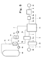
- FIG. 5 diagrammatically shows a structure of a fuel cell system according to a third embodiment of the invention.
- the structure of the fuel cell system of the third embodiment is similar to that of the second embodiment, except that heat dissipated from the cooling water by a cooling water heat radiator 13, which comprises a heat exchanger, is utilized for heating the water stored in a hot water reserve tank 45.
- a cooling water heat radiator 13 which comprises a heat exchanger
- the system of the present embodiment has the hot water reserve tank 45, a hot water pump 44 for pumping water stored in the tank 45, a hot water circulation path 15 for bringing the water sent from the tank 45 back to the tank 45 by way of the cooling water heat radiator 13.
- heat is shifted from the cooling water after utilized for the humidification in the humidifying unit 21a' to the cooling water heat radiator 13 and this heat is given to the water circulating in the hot water circulation path 15.
- the water stored in the hot water reserve tank 45 is heated and the hot water is then stored in the tank 45.
- the moisture shifted from the cooling water to the supply air in the humidification by the humidifying unit 21a' and the heat which is shifted to the supply air together with the moisture can be reduced as discussed in the second embodiment. Since the amount of heat deprived from the cooling water by the humidification is thus small, a larger amount of heat can be recovered from the cooling water and utilized for heating the water stored in the hot water reserve tank 45. Accordingly, hot water can be effectively obtained and the temperature of the hot water stored can be increased. As a result, the energy efficiency of the overall system can be improved. In addition, the hot water thus recovered is high in temperature and therefore has a wide range of applications, so that the usefulness of the heat recovered from the fuel cell 11 can be increased.
- the present embodiment has been particularly described with a case where the structure of the fuel cell system of the second embodiment is employed as the basic structure, the present embodiment including the hot water reserve tank is applicable to cases where the structure of the fuel cell system of the first embodiment is adopted as the basic structure.
- FIG. 6 diagrammatically shows a structure of a fuel cell system according to a fourth embodiment of the invention.
- the fuel cell system of the fourth embodiment has the same structure as in the third embodiment, except that the pre-humidifying unit 22 and the humidifying unit 21a' are integrally formed, in other words, a humidifying unit 50 comprised of a pre-humidifying portion 22' and a humidifying portion 21' is provided. The point of difference will be described below.
- the air path 1 and the exhaust air paths 4, 5 are connected to the pre-humidifying portion 22'.
- the air path 1 is used for supplying the supply air
- the exhaust air path 4 is used for supplying the exhaust air discharged from the fuel cell 11
- the exhaust air path 5 is used for withdrawing the exhaust air which has been used in humidification from the pre-humidifying portion 22'.
- Connected to the humidifying portion 21' are the cooling water path 6a for supplying the cooling water after cooling the fuel cell 11, the cooling water path 6b for withdrawing the cooling water which has been used in humidification from the humidifying portion 21' and the air path 3 for supplying the humidified supply air to the fuel cell 11.
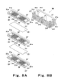
- Figures 7, 8 are views which diagrammatically show a structure of the humidifying unit 50, wherein Figure 7A, 7B are oblique perspective views of flow path plates constituting the humidifying unit 50, Figure 7A shows a surface of the flow path, and Figure 7B shows a rear face of the flow path plate.
- Figure 8A, 8B show a structure of the humidifying unit 50 formed by laminating the plural flow path plates shown in Figure 7, Figure 8A is an exploded perspective view, Figure 8B is a perspective view.
- the pre-humidifying portion 22' of the humidifying unit 50 has the same structure as the pre-humidifying units 22 of the first to third embodiments, whereas the humidifying unit 21' has the same structure as the humidifying units 21a' of the first to third embodiments. More specifically, the humidifying unit 50 has a plurality of flow path plates 27' which are laminated with a moisture transmitting film 23 interposed between every two plates 27'. Formed on the surface of each flow path plate 27' are the exhaust air flow path 25 and a cooling water flow path 26.
- each flow path plate 27' Formed on the rear face of each flow path plate 27' is the supply air flow path 24 which continuously extends throughout the pre-humidifying portion 22' and the humidifying portion 21', registering the bottoms of the exhaust air flow path 25 and the cooling water flow path 26.
- a plurality of manifold holes 31a to 31f are formed in other areas than the areas where the paths 24, 25, 26 are formed.
- the flow path plates 27' are laminated such that the manifold holes 31a to 31f of each flow path plates 27' are overlapped respectively.
- an exhaust air introducing flow path 31c' constituted by the communicating manifold holes 31c
- an exhaust air withdrawing flow path 31a' constituted by the communicating manifold holes 31a
- a cooling water introducing flow path 31f' constituted by the communicating manifold holes 31f
- a cooling water withdrawing flow path 31d' constituted by the communicating manifold holes 31d.
- a supply air introducing flow path 31b' constituted by the communicating manifold holes 31b and a supply air withdrawing flow path 31e' constituted by the communicating manifold holes 31e.
- the exhaust air introducing flow path 31c' constituted by the communicating manifold holes 31c is connected to the exhaust air path 4 and the exhaust air withdrawing flow path 31a' constituted by the communicating manifold holes 31a is connected to the exhaust air path 5.
- the exhaust air supplied from the exhaust air path 4 to the pre-humidifying portion 21' of the humidifying unit 50 flows through the exhaust air paths 25 formed on the surfaces of the flow path plates 27' to be sent to the exhaust air path 5.
- the cooling water introducing flow path 31f' constituted by the communicating manifold holes 31f is connected to the cooling water flow path 6a and the cooling water withdrawing flow path 31d' constituted by the communicating manifold holes 31d is connected to the cooling water flow path 6b.
- the cooling water supplied from the cooling water flow path 6a to the humidifying portion 21' of the flow path plates 27' of the humidifying unit 50 flows through the cooling water flow paths 26 formed on the surfaces of the plates 27' to be sent to the cooling water flow path 6b.
- a flow of exhaust air is formed in the pre-humidifying portion 22' whereas a flow of cooling water is formed in the humidifying portion 21'.
- the flows of exhaust air and cooling water have the same direction.
- the supply air introducing flow path 31b' constituted by the communicating manifold holes 31b is connected to the air path 1 and the supply air withdrawing flow path 31e' constituted by the communicating manifold holes 31e is connected to the air path 3.
- the supply air fed from the air path 1 to the pre-humidifying portion 22' of the flow path plates 27' of the humidifying unit 50 flows through the supply air flow paths 24 formed on the rear faces of the plates 27' and then flows through the supply air flow paths 24 of the humidifying portion 21'. Thereafter, the supply air is sent to the air path 3. Accordingly, the flow of supply air formed throughout the pre-humidifying portion 22' and the humidifying portion 21' has a direction opposite to the direction of the flows of exhaust air and cooling water formed on the surfaces of the plates 27'.
- the plural flow path plates 27' having the above structure are thus laminated with a moisture transmitting film 23 interposed between every two plates 27' in the humidifying unit 50, and therefore, in the pre-humidifying portion 22', the exhaust air flowing in the exhaust air flow path 25 formed on the surface of one flow path plate 27' comes in contact with the supply air flowing in the supply air flow path 24 formed on the rear face of another flow path plate 27' through a moisture transmitting film 23. Therefore, in the pre-humidifying portion 22', moisture is shifted from the exhaust air to the supply air through the moisture transmitting film 23 as discussed in the description of the pre-humidifying unit 22.
- the cooling water flowing in the cooling water flow path 26 formed on the surface of one flow path plate 27' comes in contact with the supply air flowing in the supply air flow path 24 formed on the rear face of another flow path plate 27' through the moisture transmitting film 23. Therefore, in the humidifying portion 21', moisture is shifted from the cooling water to the supply air through the moisture transmitting film 23 as discussed in the description of the humidifying unit 21a'. Since the supply air is in contact with the exhaust air and the cooling water, flowing in a direction opposite to the direction of the flow of exhaust air and the cooling water as described earlier, the transfer of the moisture and the heat energy can be effectively carried out within the pre-humidifying portion 22' and the humidifying portion 21'. In the humidifying unit 50, humidification of the supply air by use of the exhaust air is done in the pre-humidifying portion 22' whereas humidification of the supply air by use of the cooling water is further done in the humidifying portion 21'.
- the same effect as described in the third embodiment can be achieved by the fuel cell system of the above structure.
- the humidifying unit 50 having the pre-humidifying portion 22' and the humidifying portion 21' which are integral with each other, piping between the pre-humidifying portion 22' and the humidifying portion 21' (concretely, pipeline comprising the air path 2 in the third embodiment) becomes unnecessary.
- the system can be downsized while preventing the heat loss in the pipeline to achieve improved heat efficiency.
- the layout of the pre-humidifying portion 22' and the humidifying portion 21' is not limited to this.
- the pre-humidifying portion 22' and the humidifying portion 21' may be integrally laminated.
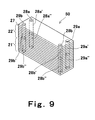
- FIG 9 is a perspective view showing a structure of the humidifying portion 50 according to a modification of the fuel cell system of the present embodiment.
- the humidifying unit 50 of this modification is designed such that the humidifying portion 21' is laminated on the pre-humidifying portion 22' so that the pre-humidifying portion 22' and the humidifying portion 21' are vertically aligned.
- the pre-humidifying portion 22' has a structure similar to the above-described pre-humidifying unit 22 while the humidifying portion 21' has a structure similar to the above-described humidifying unit 21a'.
- the air path 1 is connected to the supply air introducing flow path 28a' formed by the manifold holes 28a of the flow path plates 27 constituting the pre-humidifying portion 22'.
- the exhaust air path 4 is connected to the exhaust air withdrawing flow path 29a' formed by the manifold holes 29a
- the exhaust air path 5 is connected to the exhaust air withdrawing flow path 29b' formed by the manifold holes 29b.
- the air path 3 is connected to the supply air withdrawing flow path 28a" formed by the manifold holes 28a of the flow path plates 27 constituting the humidifying portion 21'.
- the cooling water path 6a is connected to the cooling water introducing flow path 29b" formed by the manifold holes 29b, and the cooling water path 6b is connected to the cooling water withdrawing flow path 29a" formed by the manifold holes 29a.
- the supply air withdrawing flow path 28b' formed by the manifold holes 28b in the pre-humidifying portion 22' is connected to the supply air introducing flow path 28b" formed by the manifold holes 28b in the humidifying portion 21'.
- the supply air is fed to the pre-humidifying portion 22' via the air path 1 and then flows into the supply air flow path 24 formed on the surface of each flow path plate 27, entering the supply air withdrawing flow path 28' formed by manifold holes 28b.
- the exhaust air fed to the pre-humidifying portion 22' via the exhaust air path 4 flows into the exhaust air flow path 25 formed on the rear face of each flow path plate 27 to be sent to the exhaust air path 5.
- the flows of supply air and exhaust air are formed on the surfaces and rear faces of the flow path plates 27, which oppose to each other, so that the moisture and heat energy of the exhaust air are shifted to the supply air through the water transmitting films 23, thereby performing humidification and heating of the supply air.
- the supply air thus humidified vertically flows in the supply air withdrawing flow path 28b' constituted by the manifold holes 28b and is supplied to the flow path plates 27 of the humidifying portion 21' through the supply air introducing flow path 28b" in the humidifying portion 21'.
- the supply air fed from the pre-humidifying portion 22' flows in the supply air flow path 24.
- the aforesaid flow opposed to the air supply flow paths 24 in the pre-humidifying portion 22' is formed.
- the cooling water is fed to the cooling water flow path 26 formed on the rear face of each flow path plate 27 through the cooling water path 6a.
- the cooling water flows in the cooling water flow paths 26 on the rear faces of the plates 27 to be sent to the cooling water path 6b.
- the flows of supply air and cooling water are thus formed on the surfaces and rear faces of the flow path plates 27, so that the moisture and heat energy of the cooling water is further shifted to the supply air through the moisture transmitting films 23 as described earlier, thereby performing humidification and heating of the supply air furthermore.
- the same effect as in the case where the pre-humidifying portion 22' and the humidifying portion 21' are horizontally aligned can be achieved.
- the pre-humidifying portion 22' and the humidifying portion 21' are horizontally aligned, it is unnecessary to take the step of stacking the pre-humidifying portion 22' on the humidifying portion 21' like the case of the vertical lamination of the portions 21' and 22'. Therefore, the manufacturing process can be simplified, leading to a reduction in the cost of the fuel cell system.
- FIG 10 diagrammatically shows a structure of a fuel cell system according to a fifth embodiment of the invention.
- the fuel cell system of the fifth embodiment has the same structure as the fuel cell system of the fourth embodiment except that the fuel cell 11 is adjacent to the humidifying unit 50.
- the point of difference will be described.
- the fuel cell system of the fifth embodiment is designed such that the fuel cell 11 is disposed in a position adjacent to the humidifying unit 50 of the fourth embodiment.
- the air path 1 for supplying the supply air and the exhaust air path 5 for withdrawing the exhaust air which has been used in the humidification.
- the cooling water path 7 for supplying the cooling water and the cooling water path 6 for withdrawing the cooling water which has been used in the humidification of the supply air and cooling of the fuel cell 11.
- the fuel cell 11 and the humidifying unit 50 are integrally formed, it becomes possible to supply directly the exhaust air from the fuel cell 11 to the pre-humidifying portion 22' of the humidifying unit 50.
- the cooling water can be circulated, by directly supplying it to and recovering it from the fuel cell 11 through the humidifying portion 21' of the humidifying unit 50.
- the supply air can be directly fed from the humidifying portion 21' to the fuel cell 11. Accordingly, the fuel cell system of the present embodiment enables direct feeding of the exhaust air, supply air and cooling water without providing a path composed of a pipeline etc.
- the layout of the fuel cell 11 and the humidifying unit 50 is not particularly limited. It should, however, be noted that the arrangement in which the fuel cell 11 is placed in direction of the stacking direction of the flow path plates 27 is more preferable in view of downsizing of the system, because the complicated piping is not required in this case.
- the humidifying unit 50 comprised of the pre-humidifying portion 22' integral with the humidifying portion 21' is in contact with the fuel cell 11
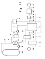
- FIG 11 diagrammatically shows a structure of a fuel cell system according to a sixth embodiment of the invention.
- the fuel cell system of the sixth embodiment has the same structure as the fuel cell system of the third embodiment except the following point.
- the air path 3 for supplying air from the humidifying unit 21a' to the fuel cell 11 is provided with a detector 60 for detecting the humidity of the supply air (concretely, the moisture of the supply air) and with a control unit 61 for controlling the flow rate of the cooling water to be supplied to the humidifying unit 21a' according to information from the detector 60.
- the control unit 61 controls the output or revolution speed of the cooling water pump 12 thereby performing the flow rate control for the cooling water.
- the detector 60 detects the humidity of the supply air fed to the fuel cell 11 by way of the air path 3.
- an electric-resistance type moisture sensor, thermistor type moisture sensor or the like may be used as the detector 60.
- the detector 60 is disposed just in front of the fuel cell 11 in the air path 3. The information on the humidity obtained by the detector 60 is transmitted to the control unit 61.
- the control unit 61 increases the output of the cooling water pump 12 or the revolution speed of the pump 12, based on the humidity information. This causes the amount of cooling water to be fed to the humidifying unit 21a' to increase and as a result, the amount of moisture shifted from the cooling water to the supply air in the humidifying unit 21a', that is, the degree of humidification is increased. Thus, the humidity of the supply air can be adjusted to an optimum value.
- the control unit 61 reduces the output of the cooling water pump 12 or the revolution speed of the pump 12, based on the humidity information. This causes the amount of cooling water to be fed to the humidifying unit 21a' to decrease and as a result, the amount of moisture shifted from the cooling water to the supply air in the humidifying unit 21a', that is, the degree of humidification is reduced. Thus, the humidity of the supply air can be adjusted to an optimum value.
- the humidity of the supply air can be optimized by controlling the flow rate of the cooling water to be supplied, according to the humidity of the supply air. This brings about an improvement in the heat efficiency and stability of the fuel cell system.
- the method of adjusting the flow rate of the cooling water is not limited to this.
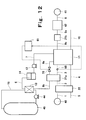
- the present embodiment may be modified such that, as shown in Figure 12, the cooling water path 6a for supplying the cooling water to the humidifying unit 21a' is provided with a proportional valve 70 which is automatically openable and closable and such that the control unit 61 controls the opening/closing of the proportional valve 70 based on the information sent from the detector 60.
- the proportional valve 70 is more widely opened according to the humidity information from the control unit 61. This causes the amount of cooling water to be fed to the humidifying unit 21a' to increase and as a result, the amount of moisture shifted from the cooling water to the supply air in the humidifying unit 21a', that is, the degree of humidification is increased.
- the control unit 61 closes the proportional valve 70 based on the humidity information such that the valve 70 is less widely opened.
- the method of adjusting humidity of the supply air is not limited this.
- the humidity of the supply air may be adjusted by controlling the temperature of the cooling water supplied to the humidifying portion 21a'.
- the temperature of the cooling water to be supplied to the humidifying unit 21a' is a factor that affects the shift of moisture from the cooling water to the supply air in the humidifying unit 21a' and therefore the temperature of the cooling water concerns the humidity of the supply air.
- the amount of moisture sifting to the supply air becomes larger when the temperature of the cooling water is high, while, the amount of moisture sifting to the supply air becomes smaller when the temperature of the cooling water is low.
- the temperature of the cooling water may be adjusted according to the humidity of the supply air by controlling the temperature of the cooling water by use of heater or the like, or by controlling the amount of radiated heat in the cooling water heat radiator 13.
- the control unit 61 controls, according to the humidity information, such heater to heat the cooling water, or the cooling water heat radiator 13 to reduce the amount of the radiated heat. This causes the rise of temperature of cooling water to be fed to the humidifying unit 21 a' to increase and as a result, the amount of moisture shifted from the cooling water to the supply air in the humidifying unit 21a', that is, the degree of humidification is increased.
- the control unit 61 controls, according to the humidity information, such heater to stop to lower the temperature of the cooling water, or the cooling water heat radiator 13 to increase the amount of the radiated heat.
- FIG 13 diagrammatically shows a structure of a fuel cell system according to a seventh embodiment of the invention.
- the fuel cell system of the seventh embodiment has the same structure as the fuel cell system of the sixth embodiment except the following point.
- a bypass path 63 bypassing the humidifying unit 21a' to circulate the cooling water is connected to the cooling water path 6a and the cooling water flow path 6b, in juxtaposition with the humidifying unit 21a'.
- a three-way valve 62 is provided in the cooling water path 6a for supplying cooling water to the humidifying unit 21a'.
- the three-way valve 62 has three pipe connection openings. Connected to the first connection opening is a pipeline 64a constituting the cooling water path 6a.
- connection opening Connected to the second connection opening is a pipeline 64b constituting the cooling water path 6a.
- a pipeline 63' constituting the bypass path 63.
- the three-way valve 62 is controlled by the control unit 61, and the distribution of the cooling water supplied from the pipeline 64a to the pipelines 63', 64b is automatically adjustable.
- the humidity of the supply air to be supplied to the fuel cell 11 via the air path 3 is detected by the detector 60, and based on the information on the humidity, the control unit 61 controls the three-way valve 62. With this arrangement, the distribution of the flow rate of the cooling water supplied from the pipeline 64a to the pipelines 64b, 63' is adjusted.
- the control unit 61 controls the three-way valve 62 based on the humidity information in such a way that the flow rate of the cooling water to be supplied to the humidifying unit 21a' increases and the flow rate of the cooling water to be supplied to the bypass path 63 decreases. This causes the flow rate of the cooling water to be fed to the humidifying unit 21a' to increase and as a result, the amount of moisture shifted from the cooling water to the supply air in the humidifying unit 21a', that is, the degree of humidification is increased. Thus, the humidity of the supply air can be adjusted to an optimum value.
- the control unit 61 controls the three-way valve 62 based on the humidity information in such a way that the flow rate of the cooling water to be supplied to the humidifying unit 21a' decreases and the flow rate of the cooling water to be supplied to the bypass path 63 increases.
- This causes the flow rate of the cooling water to be fed to the humidifying unit 21a' to decrease, and as a result, the amount of moisture to be shifted from the cooling water to the supply air in the humidifying unit 21a', that is, the degree of humidification is reduced.
- the humidity of the supply air can be adjusted to an optimum value.
- the humidity of the supply air can be optimized by controlling the flow rate of the cooling water to be supplied to the humidifying unit 21a', according to the humidity of the supply air. Accordingly, the same effect as in the sixth embodiment can be achieved. Further, in the system of the present embodiment, since the humidifying unit 21a' can be bypassed for circulation of the cooling water, the flow rate of the cooling water to be supplied to the fuel cell 11 and the flow rate of the cooling water to be supplied to the humidifying unit 21a' are independently adjustable.
- the cooling water can be supplied to the humidifying unit 21a' in an optimum amount for the humidification of the supply air, while excessive cooling water can be circulated by way of the bypass path 63 without passing through the humidifying unit 21a'.
- the waste of moisture and heat energy of the cooling water in the humidifying portion 21a' can be restrained and the consumption of the moisture and heat energy of the cooling water can be reduced
- optimally humidified supply air can be effectively obtained and the intrinsic function of the cooling water, that is, cooling of the fuel cell 11 can be effectively and stably carried out, thereby optimizing the operation temperature of the fuel cell 11.
- heat can be effectively transferred from the cooling water to the stored hot water. Consequently, both the stability and heat efficiency of the fuel cell system can be further improved.
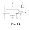
- FIG 14 diagrammatically shows part of the structure of a fuel cell system according a modification of the present embodiment.
- the humidifying unit 21a and its periphery are shown.
- the pipeline 63' constituting the bypass path 63 is connected to a pipeline 6a' constituting the cooling water path 6a and to a pipeline 6b' constituting the cooling water flow path 6b.
- the pipeline 6a' has a proportional valve 70a which is located in the downstream of the connecting point of the pipeline 63'.
- the pipeline 63' has, a proportional valve 70b, which is located at the end of the connecting point of the pipeline 6a.
- the opening and closing of the proportional valves 70a and 70b is automatically controllable by the control unit 61.
- the control unit 61 controls the proportional valve 70a such that the flow rate of the cooling water to be supplied to the humidifying unit 21a' increases and controls the proportional valve 70b such that the flow rate of the cooling water to be supplied to the bypass path 63 decreases.
- the control unit 61 controls the proportional valve 70a such that the flow rate of the cooling water to be supplied to the humidifying unit 21a' decreases and controls the proportional valve 70b such that the flow rate of the cooling water to be supplied to the bypass path 63 increases.
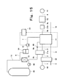
- FIG 15 diagrammatically illustrates a structure of a fuel cell system according to an eighth embodiment of the invention.
- the fuel cell system of the eighth embodiment has the same structure as in the sixth embodiment, except that a detector 65 for detecting the temperature of the cooling water to be supplied to the humidifying unit 21a' is provided instead of the detector 60 for detecting the humidity of the supply air. The point of difference will be described below.
- the temperature of the cooling water concerns the humidity of the supply air.
- the fuel cell system of the present embodiment is designed such that the detector 65 detects the temperature of the cooling water to be supplied to the humidifying unit 21a' and according to the temperature information, the control unit 61 controls the flow rate of the cooling water to be supplied to the humidifying unit 21a'.
- the detector 65 an electric-resistance type temperature sensor, contact type temperature sensor or the like may be used.
- the detector 65 is disposed just in front of the humidifying unit 21a' in the cooling water path 6a.
- the control unit 61 increases the output of the cooling water pump 12 or the revolution speed of the pump 12 based on the information on the temperature of the cooling water. This causes the flow rate of the cooling water to be supplied to the humidifying unit 21a' to increase and as a result, the amount of moisture shifted from the cooling water to the supply air in the humidifying unit 21a', that is, the degree of humidification increases.
- the humidity of the supply air can be optimized.
- the control unit 61 reduces the output of the cooling water pump 12 or the revolution speed of the pump 12 based on the information on the temperature of the cooling water. This causes the flow rate of the cooling water to be supplied to the humidifying unit 21a' to decrease and as a result, the amount of moisture shifted from the cooling water to the supply air in the humidifying unit 21a', that is, the degree of humidification decreases. Therefore, the humidity of the supply air can be optimized.
- the cooling water path 6a may be provided with a proportional valve which is used for the adjustment of the flow rate of the cooling water, as discussed in the sixth embodiment.
- the humidity of the supply air may be controlled by controlling the temperature of the cooling water instead of the flow rate of the cooling water.
- the above discussion is associated with a case where the basic structure of the fuel cell system is the same as that of the third embodiment, but the basic structure of the systems of the present embodiment may be the same as the structure of the system of any of the second, fourth and fifth embodiments. Further, the present embodiment may be applied to the structure of the fuel cell system of the seventh embodiment, that is, the bypass path 63 for bypassing the humidifying unit 21a' may be employed in the present embodiment.
- FIG 16 diagrammatically illustrates a structure of a fuel cell system according to a ninth embodiment of the invention.
- the fuel cell system of the ninth embodiment has the same structure as in the sixth embodiment, except that a detector 66 for detecting the amount of electricity generated by the fuel cell 11 is provided instead of the detector 60 for detecting the humidity of the supply air.
- a power meter may be used. Since the fuel cell system is usually operated while detecting the amount of generated electricity, it is not necessary to provide another power meter and the power meter originally provided for the system can be utilized as the detector 66.
- the difference between the ninth and sixth embodiments will be described.
- the amount of electricity generated by the fuel cell 11 corresponds to the amount of air to be supplied to the air pole side and the amount of fuel gas to be supplied to the fuel pole side. If a large amount of electricity is generated by the fuel cell 11, the flow rate of the air to be supplied to the fuel cell 11 becomes high. Therefore, the flow rate of the cooling water to be supplied to the humidifying unit 21a' needs to be increased in order to humidify the supply air. On the other hand, if a small amount of electricity is generated by the fuel cell 11, the flow rate of the air to be supplied to the fuel cell 11 becomes low, and therefore, the flow rate of the cooling water to be supplied to the humidifying unit 21a' for humidification of the supply air may be low. Thus, the humidity of the supply air can be optimized by adjusting the flow rate of the cooling water to be supplied to the humidifying unit 21a' according to the amount of electricity generated by the fuel cell 11.
- the control unit 61 increases the output of the cooling water pump 12 or the revolution speed of the cooling water pump 12 based on the electricity amount information sent from the detector 66, thereby increasing the amount of cooling water to be supplied to the humidifying unit 21a'. With this arrangement, optimum humidification can be performed on the supply air having a high the flow rate.
- the control unit 61 reduces the output of the cooling water pump 12 or the revolution speed of the cooling water pump 12 based on the electricity amount information sent from the detector 66, thereby reducing the amount of cooling water to be supplied to the humidifying unit 21a'. Thanks to this arrangement, optimum humidification can be performed on the supply air.
- the flow rate of cooling water to be supplied to the humidifying unit 21a' is controlled depending on the amount of electricity generated by the fuel cell 11, air humidified to an optimum degree can be stably supplied in accordance with the operating state of the fuel cell 11. Accordingly, the same effect as in the sixth embodiment can be obtained. Since the power meter originally provided for the system can be as the detector 66 as discussed earlier, there is no need to provide another detector for controlling the degree of humidification so that simplification of the system and cost reduction can be achieved.
- the adjusting method for the flow rate of the cooling water is not limited to this.
- the cooling water path 6a may be provided with a proportional valve which is used for the adjustment, as described in the third embodiment.
- the humidity of the supply air may be controlled by controlling the temperature of the cooling water instead of the flow rate of the cooling water.
- the humidity of the supply air is controlled according to the amount of electricity generated by the fuel cell 11 in the above discussion, it is readily apparent that the flow rate of the supply air to be supplied to the fuel cell 11 may be directly detected and the humidity of the supply air may be controlled according the flow rate of the supply air.
- a detector for detecting the flow rate of the supply air is disposed just in front of the fuel cell 11 in the air path 3, and if the flow rate of the supply air detected by the detector is high, the transfer of moisture to the air is promoted as described earlier, thereby increasing humidity.
- the flow rate of the supply air detected by the detector is low, the transfer of moisture to the air is restricted as described earlier, thereby reducing humidity.
- the above discussion is associated with a case where the basic structure of the fuel cell system is the same as that of the third embodiment, but the basic structure of the fuel cell system of the present embodiment may be the same as the structure of the fuel cell system of any of the second, fourth and fifth embodiments.
- the present embodiment may be applied to the structure of the fuel cell system of the seventh embodiment, that is, the bypass path 63 for bypassing the humidifying unit 21a' may be employed in the present embodiment.
- the pre-humidifying unit 22/the pre-humidifying portion 22' and the humidifying unit 21a'/ the humidifying portion 21' have a structure formed by lamination of a plurality of flow path plates 27, 27' with a moisture transmitting film 23 between every two plates (i.e., the so-called plate-like structure, the structure of these members is not limited to the plate-like structure.
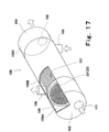
- the pre-humidifying unit 22, the pre-humidifying portion 22', the humidifying unit 21a' and the humidifying portion 21' may have a tube-like structure.
- the pre-humidifying unit of a tube-like structure will be exemplified below.
- FIG 17 is a diagrammatical cut-away perspective view showing the structure of the pre-humidifying unit 22 having a tube-like structure.
- the pre-humidifying unit 22 comprises a cylindrical main body 100 having, at its circumferential surface, a supply air inlet 105 and a supply air outlet 106,and at both ends of which is sealed by circular plates 103, 104 having an exhaust air inlet 101 and an exhaust air outlet 102.
- a moisture transmitting module 107 is accommodated so as to have the same axial direction as that of the main body 100, the module 107 being composed of a plurality of hollow string - like fibers 23' tied in a bundle which are composed of moisture transmitting films 23.
- the exhaust air path 4 (not shown) is connected to the exhaust air inlet 101 of the main body 100; the exhaust air path 5 (not shown) is connected to the exhaust air outlet 102; the supply air path 1 (not shown) is connected to the supply air inlet 105; and the supply air path 2 (not shown) is connected to the supply air outlet 106.
- a sealing member 108 is attached to both ends of the moisture transmitting film module 107, whereby the inside of the main body 100 is divided into (a) a first space 109A communicating with the exhaust air path 4 by way of the exhaust air inlet 101; (b) a second space 109B being formed in the periphery of the moisture transmitting module 107 and communicating with the supply air paths 1, 2 by way of the supply air inlet 105 and the supply air outlet 106 respectively; and (c) a third space 109C communicating with the exhaust air path 5 by way of the exhaust air outlet 102.
- the supply air is fed to the second space 109B of the main body 100 through the supply air inlet 105, whereas the supply air being withdrawn from the space 109B through the supply air outlet 106.
- the exhaust air which has been fed to the first space 109A of the main body 100 through the exhaust air inlet 101 goes into the moisture transmitting film module 107 from one end surface thereof.
- the exhaust air flows in the axial direction of the hollow siring - like fibers 23' constituting the moisture transmitting film module 107 within each of them. Thereafter, the exhaust air is released from the other end of the module to the third space 109C and taken out of the exhaust air outlet 102. With this arrangement, a flow of exhaust air from the first space 109A to the third space 109C is formed.
- the supply air flow path formed in the respective peripheries of the moisture transmitting film module 107 and the hollow string-like fibers 23' constituting the film module 107 contacts the exhaust air flow path formed within the hollow string-like fibers 23' of the film module 107, through a moisture transmitting film 23. Therefore, moisture and heat energy are shifted from the exhaust air to the supply air through a moisture transmitting film 23, similarly to the case of the plate-like structure described earlier.
- the supply air heated and humidified by the exhaust air can be withdrawn from the main body 100.
- the fuel cell system having the pre-humidifying unit 22 of the tube-like structure provides the same effect as described above.
- the tube-like structure has been explained with the pre-humidifying unit 22, it should be noted that the tube-like structure shown in Figure 17 is applicable to the pre-humidifying portion 22', the humidifying unit 21a' and the humidifying portion 21'.
- the present invention is implemented in the forms discussed above and has the following effects.
- the fuel cell system of the invention is capable of providing improved energy efficiency while performing stable system operation.
- compact and simplified system configuration is possible.
Landscapes
- Life Sciences & Earth Sciences (AREA)
- Engineering & Computer Science (AREA)
- Manufacturing & Machinery (AREA)
- Sustainable Development (AREA)
- Sustainable Energy (AREA)
- Chemical & Material Sciences (AREA)
- Chemical Kinetics & Catalysis (AREA)
- Electrochemistry (AREA)
- General Chemical & Material Sciences (AREA)
- Fuel Cell (AREA)
Applications Claiming Priority (2)
| Application Number | Priority Date | Filing Date | Title |
|---|---|---|---|
| JP2002111687 | 2002-04-15 | ||
| JP2002111687 | 2002-04-15 |
Publications (3)
| Publication Number | Publication Date |
|---|---|
| EP1369945A2 true EP1369945A2 (de) | 2003-12-10 |
| EP1369945A3 EP1369945A3 (de) | 2007-07-11 |
| EP1369945B1 EP1369945B1 (de) | 2012-08-15 |
Family
ID=29243285
Family Applications (1)
| Application Number | Title | Priority Date | Filing Date |
|---|---|---|---|
| EP03008589A Expired - Lifetime EP1369945B1 (de) | 2002-04-15 | 2003-04-14 | Brenstoffzellen-System |
Country Status (5)
| Country | Link |
|---|---|
| US (2) | US20030219638A1 (de) |
| EP (1) | EP1369945B1 (de) |
| JP (1) | JP2010147029A (de) |
| KR (1) | KR100562614B1 (de) |
| CN (1) | CN1312799C (de) |
Cited By (2)
| Publication number | Priority date | Publication date | Assignee | Title |
|---|---|---|---|---|
| WO2008000001A1 (de) * | 2006-06-29 | 2008-01-03 | Avl List Gmbh | Verfahren und vorrichtung zur konditionierung eines o2-hältigen gases |
| EP1564831A3 (de) * | 2004-02-13 | 2010-11-03 | Mitsubishi Denki Kabushiki Kaisha | Wärme-Feuchtaustauscher |
Families Citing this family (16)
| Publication number | Priority date | Publication date | Assignee | Title |
|---|---|---|---|---|
| JP4147924B2 (ja) * | 2002-12-03 | 2008-09-10 | 日産自動車株式会社 | 燃料電池システム |
| KR100534698B1 (ko) | 2003-07-11 | 2005-12-07 | 현대자동차주식회사 | 연료전지 시스템 |
| JP4622313B2 (ja) * | 2003-08-26 | 2011-02-02 | トヨタ自動車株式会社 | 移動体 |
| US20080063902A1 (en) * | 2004-05-19 | 2008-03-13 | Yoshitaka Kawasaki | Fuel Cell System |
| JP2006221868A (ja) * | 2005-02-08 | 2006-08-24 | Toshiba Corp | 燃料電池 |
| CN100570939C (zh) * | 2005-05-27 | 2009-12-16 | 丰田自动车株式会社 | 燃料电池系统及燃料电池的运转方法 |
| JP5032762B2 (ja) * | 2005-10-31 | 2012-09-26 | キヤノン株式会社 | 電子機器 |
| JP2007323969A (ja) * | 2006-06-01 | 2007-12-13 | Fuji Electric Holdings Co Ltd | 燃料電池発電装置 |
| EP1864946A2 (de) * | 2006-06-07 | 2007-12-12 | Michigan Technology Co., Ltd. | Druckausgleichssystem für oxidierendes Gas |
| DE102007003938A1 (de) * | 2007-01-26 | 2008-07-31 | Daimler Ag | Brennstoffzellensystem mit Ultraschalldetektor |
| ATE512475T1 (de) * | 2007-02-09 | 2011-06-15 | Daimler Ag | Versorgungssystem und warnvorrichtung für einen brennstoffzellenstapel sowie verfahren zur kontrolle des versorgungssystems |
| US7771885B2 (en) * | 2007-03-30 | 2010-08-10 | Panasonic Corporation | Polymer electrolyte fuel cell and manufacturing method for electrode-membrane-frame assembly |
| CN102152636B (zh) * | 2009-11-12 | 2015-04-01 | 佳能株式会社 | 记录设备和记录方法 |
| KR101428186B1 (ko) * | 2012-08-30 | 2014-09-23 | 현대자동차주식회사 | 연료전지용 막 가습 장치 |
| KR102063947B1 (ko) * | 2013-12-27 | 2020-01-08 | 에스케이이노베이션 주식회사 | 연료 전지 발열량의 제어 장치 |
| KR102552485B1 (ko) * | 2016-12-16 | 2023-07-06 | 현대자동차주식회사 | 연료전지 시스템 |
Citations (1)
| Publication number | Priority date | Publication date | Assignee | Title |
|---|---|---|---|---|
| EP1182720A1 (de) | 1999-12-28 | 2002-02-27 | Daikin Industries, Ltd. | Befeuchtungsvorrichtung für brennstoffzellen |
Family Cites Families (21)
| Publication number | Priority date | Publication date | Assignee | Title |
|---|---|---|---|---|
| JPH06124722A (ja) | 1992-10-09 | 1994-05-06 | Mitsubishi Heavy Ind Ltd | 加温・加湿システム装置及び燃料電池 |
| JP3111697B2 (ja) | 1992-10-20 | 2000-11-27 | 富士電機株式会社 | 固体高分子電解質型燃料電池 |
| JPH06338338A (ja) | 1993-05-28 | 1994-12-06 | Mitsubishi Heavy Ind Ltd | 燃料電池の高分子イオン交換膜の加湿方法 |
| US5360679A (en) * | 1993-08-20 | 1994-11-01 | Ballard Power Systems Inc. | Hydrocarbon fueled solid polymer fuel cell electric power generation system |
| JPH07288134A (ja) | 1994-04-19 | 1995-10-31 | Kansai Electric Power Co Inc:The | 固体高分子電解質型燃料電池の運転方法 |
| JP3514880B2 (ja) | 1995-06-23 | 2004-03-31 | 田中貴金属工業株式会社 | Pem型燃料電池のガス加湿器 |
| US6045933A (en) * | 1995-10-11 | 2000-04-04 | Honda Giken Kogyo Kabushiki Kaisha | Method of supplying fuel gas to a fuel cell |
| JPH10255828A (ja) * | 1997-03-13 | 1998-09-25 | Honda Motor Co Ltd | 燃料電池およびその制御方法 |
| JP3823439B2 (ja) * | 1997-05-09 | 2006-09-20 | ダイキン工業株式会社 | 燃料電池駆動空調システム |
| US6013385A (en) * | 1997-07-25 | 2000-01-11 | Emprise Corporation | Fuel cell gas management system |
| JP2000188119A (ja) * | 1998-12-21 | 2000-07-04 | Aisin Seiki Co Ltd | 燃料電池システムおよびその制御方法 |
| JP4200576B2 (ja) * | 1999-02-23 | 2008-12-24 | トヨタ自動車株式会社 | 燃料電池システム |
| IT1314256B1 (it) * | 1999-12-03 | 2002-12-06 | Nora Fuel Cells S P A De | Batteria di celle a combustibile a membrana polimerica. |
| JP2001167779A (ja) * | 1999-12-14 | 2001-06-22 | Isuzu Motors Ltd | 車両用燃料電池システム |
| US6376111B1 (en) * | 2000-01-25 | 2002-04-23 | General Motors Corporation | System and method for controlling the humidity level of a fuel cell |
| US6656620B2 (en) * | 2000-01-31 | 2003-12-02 | Honda Giken Kogyo Kabushiki Kaisha | Humidification system for a fuel cell |
| JP2001216984A (ja) | 2000-01-31 | 2001-08-10 | Honda Motor Co Ltd | 燃料電池用加湿システム |
| TW496010B (en) * | 2000-03-23 | 2002-07-21 | Sanyo Electric Co | Solid high molcular type fuel battery |
| JP2002075423A (ja) * | 2000-09-01 | 2002-03-15 | Honda Motor Co Ltd | 燃料電池用加湿装置 |
| JP4801261B2 (ja) * | 2001-01-23 | 2011-10-26 | 本田技研工業株式会社 | 燃料電池システム |
| JP2002246049A (ja) * | 2001-02-16 | 2002-08-30 | Daikin Ind Ltd | 燃料電池用加湿装置 |
-
2003
- 2003-04-14 EP EP03008589A patent/EP1369945B1/de not_active Expired - Lifetime
- 2003-04-14 KR KR1020030023450A patent/KR100562614B1/ko not_active Expired - Fee Related
- 2003-04-14 US US10/414,143 patent/US20030219638A1/en not_active Abandoned
- 2003-04-15 CN CNB031218601A patent/CN1312799C/zh not_active Expired - Fee Related
-
2010
- 2010-01-21 JP JP2010011402A patent/JP2010147029A/ja active Pending
- 2010-06-21 US US12/819,519 patent/US8129062B2/en not_active Expired - Fee Related
Patent Citations (1)
| Publication number | Priority date | Publication date | Assignee | Title |
|---|---|---|---|---|
| EP1182720A1 (de) | 1999-12-28 | 2002-02-27 | Daikin Industries, Ltd. | Befeuchtungsvorrichtung für brennstoffzellen |
Cited By (2)
| Publication number | Priority date | Publication date | Assignee | Title |
|---|---|---|---|---|
| EP1564831A3 (de) * | 2004-02-13 | 2010-11-03 | Mitsubishi Denki Kabushiki Kaisha | Wärme-Feuchtaustauscher |
| WO2008000001A1 (de) * | 2006-06-29 | 2008-01-03 | Avl List Gmbh | Verfahren und vorrichtung zur konditionierung eines o2-hältigen gases |
Also Published As
| Publication number | Publication date |
|---|---|
| JP2010147029A (ja) | 2010-07-01 |
| EP1369945A3 (de) | 2007-07-11 |
| EP1369945B1 (de) | 2012-08-15 |
| US20100255390A1 (en) | 2010-10-07 |
| US8129062B2 (en) | 2012-03-06 |
| CN1312799C (zh) | 2007-04-25 |
| KR100562614B1 (ko) | 2006-03-17 |
| KR20030082418A (ko) | 2003-10-22 |
| US20030219638A1 (en) | 2003-11-27 |
| CN1452263A (zh) | 2003-10-29 |
Similar Documents
| Publication | Publication Date | Title |
|---|---|---|
| US8129062B2 (en) | Fuel cell system operation method | |
| US8304123B2 (en) | Ambient pressure fuel cell system employing partial air humidification | |
| CA2242176C (en) | Solid polymer fuel cell system and method for humidifying and adjusting the temperature of a reactant stream | |
| US6783878B2 (en) | Solid polymer fuel cell system and method for humidifying and adjusting the temperature of a reactant stream | |
| EP0878860B1 (de) | Verfahren zum Betrieb einer Polymerelektrolyt-Brennstoffzelle mit innerer Befeuchtung | |
| JP3699063B2 (ja) | 燃料電池およびその制御方法 | |
| JPH10247505A (ja) | 固体高分子電解質型燃料電池 | |
| CN101496216B (zh) | 燃料电池和燃料电池系统 | |
| JP3843046B2 (ja) | 固体高分子形燃料電池システム | |
| EP1284515A2 (de) | Gaserzeugungssystem für eine Brennstoffzelle und Abwärme-Rückführung und Kühlsystem für dieses Erzeugungssystem | |
| JP4464066B2 (ja) | 燃料電池システム | |
| JP2002170584A (ja) | 固体高分子形燃料電池 | |
| JP2004111397A (ja) | 燃料電池における反応体流の加湿 | |
| US8298710B2 (en) | Humidifier for fuel cell and process for warming the same | |
| JP2914898B2 (ja) | 固体高分子型燃料電池システム | |
| US7067209B2 (en) | High temperature reactant recycling for PEM fuel cell humidification | |
| JP2004119044A (ja) | 移動体用燃料電池システム | |
| JP5098832B2 (ja) | 燃料電池システム | |
| JP5266635B2 (ja) | 燃料電池システム | |
| JP2006156251A (ja) | 燃料電池システム | |
| JP2002117883A (ja) | 燃料電池システム | |
| JP2007294347A (ja) | 燃料電池システム | |
| JP2009301723A (ja) | 燃料電池用ガスの加湿装置 |
Legal Events
| Date | Code | Title | Description |
|---|---|---|---|
| PUAI | Public reference made under article 153(3) epc to a published international application that has entered the european phase |
Free format text: ORIGINAL CODE: 0009012 |
|
| 17P | Request for examination filed |
Effective date: 20030414 |
|
| AK | Designated contracting states |
Kind code of ref document: A2 Designated state(s): AT BE BG CH CY CZ DE DK EE ES FI FR GB GR HU IE IT LI LU MC NL PT RO SE SI SK TR |
|
| AX | Request for extension of the european patent |
Extension state: AL LT LV MK RO |
|
| PUAL | Search report despatched |
Free format text: ORIGINAL CODE: 0009013 |
|
| AK | Designated contracting states |
Kind code of ref document: A3 Designated state(s): AT BE BG CH CY CZ DE DK EE ES FI FR GB GR HU IE IT LI LU MC NL PT RO SE SI SK TR |
|
| AX | Request for extension of the european patent |
Extension state: AL LT LV MK RO |
|
| AKX | Designation fees paid |
Designated state(s): DE FR GB |
|
| RAP1 | Party data changed (applicant data changed or rights of an application transferred) |
Owner name: PANASONIC CORPORATION |
|
| 17Q | First examination report despatched |
Effective date: 20110901 |
|
| GRAP | Despatch of communication of intention to grant a patent |
Free format text: ORIGINAL CODE: EPIDOSNIGR1 |
|
| GRAS | Grant fee paid |
Free format text: ORIGINAL CODE: EPIDOSNIGR3 |
|
| GRAA | (expected) grant |
Free format text: ORIGINAL CODE: 0009210 |
|
| AK | Designated contracting states |
Kind code of ref document: B1 Designated state(s): DE FR GB |
|
| REG | Reference to a national code |
Ref country code: GB Ref legal event code: FG4D |
|
| REG | Reference to a national code |
Ref country code: DE Ref legal event code: R096 Ref document number: 60341806 Country of ref document: DE Effective date: 20121011 |
|
| PLBE | No opposition filed within time limit |
Free format text: ORIGINAL CODE: 0009261 |
|
| STAA | Information on the status of an ep patent application or granted ep patent |
Free format text: STATUS: NO OPPOSITION FILED WITHIN TIME LIMIT |
|
| 26N | No opposition filed |
Effective date: 20130516 |
|
| REG | Reference to a national code |
Ref country code: DE Ref legal event code: R097 Ref document number: 60341806 Country of ref document: DE Effective date: 20130516 |
|
| REG | Reference to a national code |
Ref country code: FR Ref legal event code: PLFP Year of fee payment: 14 |
|
| REG | Reference to a national code |
Ref country code: FR Ref legal event code: PLFP Year of fee payment: 15 |
|
| PGFP | Annual fee paid to national office [announced via postgrant information from national office to epo] |
Ref country code: FR Payment date: 20170419 Year of fee payment: 15 Ref country code: DE Payment date: 20170419 Year of fee payment: 15 Ref country code: GB Payment date: 20170419 Year of fee payment: 15 |
|
| REG | Reference to a national code |
Ref country code: DE Ref legal event code: R119 Ref document number: 60341806 Country of ref document: DE |
|
| GBPC | Gb: european patent ceased through non-payment of renewal fee |
Effective date: 20180414 |
|
| PG25 | Lapsed in a contracting state [announced via postgrant information from national office to epo] |
Ref country code: DE Free format text: LAPSE BECAUSE OF NON-PAYMENT OF DUE FEES Effective date: 20181101 |
|
| PG25 | Lapsed in a contracting state [announced via postgrant information from national office to epo] |
Ref country code: GB Free format text: LAPSE BECAUSE OF NON-PAYMENT OF DUE FEES Effective date: 20180414 |
|
| PG25 | Lapsed in a contracting state [announced via postgrant information from national office to epo] |
Ref country code: FR Free format text: LAPSE BECAUSE OF NON-PAYMENT OF DUE FEES Effective date: 20180430 |