EP1369279A1 - Getriebesteuereinrichtung für ein Fahrzeug - Google Patents
Getriebesteuereinrichtung für ein Fahrzeug Download PDFInfo
- Publication number
- EP1369279A1 EP1369279A1 EP03009758A EP03009758A EP1369279A1 EP 1369279 A1 EP1369279 A1 EP 1369279A1 EP 03009758 A EP03009758 A EP 03009758A EP 03009758 A EP03009758 A EP 03009758A EP 1369279 A1 EP1369279 A1 EP 1369279A1
- Authority
- EP
- European Patent Office
- Prior art keywords
- speed
- internal combustion
- combustion engine
- rotating machine
- electric rotating
- Prior art date
- Legal status (The legal status is an assumption and is not a legal conclusion. Google has not performed a legal analysis and makes no representation as to the accuracy of the status listed.)
- Granted
Links
Images


Classifications
-
- F—MECHANICAL ENGINEERING; LIGHTING; HEATING; WEAPONS; BLASTING
- F02—COMBUSTION ENGINES; HOT-GAS OR COMBUSTION-PRODUCT ENGINE PLANTS
- F02B—INTERNAL-COMBUSTION PISTON ENGINES; COMBUSTION ENGINES IN GENERAL
- F02B67/00—Engines characterised by the arrangement of auxiliary apparatus not being otherwise provided for, e.g. the apparatus having different functions; Driving auxiliary apparatus from engines, not otherwise provided for
- F02B67/04—Engines characterised by the arrangement of auxiliary apparatus not being otherwise provided for, e.g. the apparatus having different functions; Driving auxiliary apparatus from engines, not otherwise provided for of mechanically-driven auxiliary apparatus
- F02B67/06—Engines characterised by the arrangement of auxiliary apparatus not being otherwise provided for, e.g. the apparatus having different functions; Driving auxiliary apparatus from engines, not otherwise provided for of mechanically-driven auxiliary apparatus driven by means of chains, belts, or like endless members
-
- F—MECHANICAL ENGINEERING; LIGHTING; HEATING; WEAPONS; BLASTING
- F02—COMBUSTION ENGINES; HOT-GAS OR COMBUSTION-PRODUCT ENGINE PLANTS
- F02N—STARTING OF COMBUSTION ENGINES; STARTING AIDS FOR SUCH ENGINES, NOT OTHERWISE PROVIDED FOR
- F02N15/00—Other power-operated starting apparatus; Component parts, details, or accessories, not provided for in, or of interest apart from groups F02N5/00 - F02N13/00
- F02N15/02—Gearing between starting-engines and started engines; Engagement or disengagement thereof
- F02N15/04—Gearing between starting-engines and started engines; Engagement or disengagement thereof the gearing including disengaging toothed gears
- F02N15/043—Gearing between starting-engines and started engines; Engagement or disengagement thereof the gearing including disengaging toothed gears the gearing including a speed reducer
- F02N15/046—Gearing between starting-engines and started engines; Engagement or disengagement thereof the gearing including disengaging toothed gears the gearing including a speed reducer of the planetary type
-
- F—MECHANICAL ENGINEERING; LIGHTING; HEATING; WEAPONS; BLASTING
- F16—ENGINEERING ELEMENTS AND UNITS; GENERAL MEASURES FOR PRODUCING AND MAINTAINING EFFECTIVE FUNCTIONING OF MACHINES OR INSTALLATIONS; THERMAL INSULATION IN GENERAL
- F16H—GEARING
- F16H3/00—Toothed gearings for conveying rotary motion with variable gear ratio or for reversing rotary motion
- F16H3/44—Toothed gearings for conveying rotary motion with variable gear ratio or for reversing rotary motion using gears having orbital motion
- F16H3/46—Gearings having only two central gears, connected by orbital gears
- F16H3/48—Gearings having only two central gears, connected by orbital gears with single orbital gears or pairs of rigidly-connected orbital gears
- F16H3/52—Gearings having only two central gears, connected by orbital gears with single orbital gears or pairs of rigidly-connected orbital gears comprising orbital spur gears
- F16H3/54—Gearings having only two central gears, connected by orbital gears with single orbital gears or pairs of rigidly-connected orbital gears comprising orbital spur gears one of the central gears being internally toothed and the other externally toothed
-
- F—MECHANICAL ENGINEERING; LIGHTING; HEATING; WEAPONS; BLASTING
- F16—ENGINEERING ELEMENTS AND UNITS; GENERAL MEASURES FOR PRODUCING AND MAINTAINING EFFECTIVE FUNCTIONING OF MACHINES OR INSTALLATIONS; THERMAL INSULATION IN GENERAL
- F16H—GEARING
- F16H55/00—Elements with teeth or friction surfaces for conveying motion; Worms, pulleys or sheaves for gearing mechanisms
- F16H55/32—Friction members
- F16H55/36—Pulleys
- F16H55/49—Features essential to V-belts pulleys
Definitions
- switching between a speed increasing mode and a constant speed mode is determined primarily depending on a centrifugal force exerting on the semple plunger 112, i.e., an engine speed of the internal combustion engine. Therefore, in the case of controlling the charging generator for increasing speed, another problem exists in that conditions of electrical loads or a remaining capacity of a battery is not involved. A further problem exists in that switching cannot be carried out under optimum conditions utilizing various signal data such as cooling water temperature of the internal combustion engine, vehicle velocity, and shift position location.
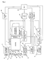
- a power transmission control device for vehicle includes: an electric rotating machine that is mounted on an internal combustion engine and functions as an electric motor and a generator; a crank pulley that is mounted on a crankshaft of the internal combustion engine and drives the electric rotating machine by power transmission means; a planetary gear mechanism consisting of a sun gear coupled to the crank pulley, a planetary gear supported on a carrier coupled to the crankshaft, and an internal gear controlled to be either a constraint state or a non-constraint state by means of an electromagnetic clutch; and control means that controls the electric rotating machine and the electromagnetic clutch.
- the electromagnetic clutch 21 of the power transmission 4 is in an OFF state, and the internal combustion engine 1 is stopped, thereby the crank pulley 15 being free. More specifically, supposing that the electric rotating machine 5 rotates clockwise viewed from a principal surface side of the electric rotating machine pulley 14, the crank pulley 15 and the sun gear 18, which are connected to the electric rotating machine pulley 14 through the belt 17, also rotate clockwise. Although the planetary gear 19 rotates on its axis counterclockwise, the internal combustion engine 1 is stopped so that the carrier 23 is also stopped, and the planetary gear 19 does not revolve round the sun. Accordingly, the outer circumferential bracket 27 and the internal gear 20, which are in a state of non-constraint due to OFF of the electromagnetic clutch 21, rotate counterclockwise.
- the internal combustion engine ECU 80 idles up rotation of the internal combustion engine 1 within a range of not higher than a first predetermined engine speed shown in the chart at the point of time "f". This idle up is implemented on conditions that the A/T is not driven, no accelerator is operated, and the vehicle is stopping.
- the one-way clutch 22 is brought into connection owing to decrease in rotation of the electric rotating machine 5, and rotates at a speed determined on the basis of a pulley ratio with respect to the internal combustion engine 1 at the point of time "h". (In Fig. 4, the point of time "h" indicates switching off the rapid catalyst heating. However, connection of the one-way clutch 22 is irrelative to this switching off.)
- An inverter that supplies a phase-controlled compensation current generates an electric power, changing contents of a PWM control of the inverter that is used for causing the electric rotating machine 5 to function as an electric motor.
- the electric rotating machine 5 can possess the mentioned two power generation modes. Accordingly, to augment an output at a low-speed rotation of the internal combustion engine 1, the inverter power generation mode and the speed-increasing high-output power generation mode can be used. However, because power generation efficiency in the inverter power generation mode is lower than in the alternator power generation mode, the alternator power generation mode is used for augmenting the output in the speed-increasing high-output power generation mode.
- the foregoing description is made on the assumption that the electric rotating machine 5 includes functions as an electric motor as well as an generator. The invention can be applied to the case where the electric rotating machine has only one function as a generator.
Applications Claiming Priority (2)
| Application Number | Priority Date | Filing Date | Title |
|---|---|---|---|
| JP2002163238 | 2002-06-04 | ||
| JP2002163238A JP3810345B2 (ja) | 2002-06-04 | 2002-06-04 | 車両用伝動制御装置 |
Publications (2)
| Publication Number | Publication Date |
|---|---|
| EP1369279A1 true EP1369279A1 (de) | 2003-12-10 |
| EP1369279B1 EP1369279B1 (de) | 2005-03-16 |
Family
ID=29545692
Family Applications (1)
| Application Number | Title | Priority Date | Filing Date |
|---|---|---|---|
| EP03009758A Expired - Fee Related EP1369279B1 (de) | 2002-06-04 | 2003-05-06 | Getriebesteuereinrichtung für ein Fahrzeug |
Country Status (4)
| Country | Link |
|---|---|
| US (1) | US6878094B2 (de) |
| EP (1) | EP1369279B1 (de) |
| JP (1) | JP3810345B2 (de) |
| DE (1) | DE60300384T2 (de) |
Cited By (14)
| Publication number | Priority date | Publication date | Assignee | Title |
|---|---|---|---|---|
| EP2108803A1 (de) * | 2008-04-10 | 2009-10-14 | Behr GmbH & Co. KG | Verfahren zum Heizen einer Fahrgastzelle und Verfahren zum Einstellen eines verstellbaren Getriebes |
| EP1455085A3 (de) * | 2003-03-04 | 2009-12-16 | HONDA MOTOR CO., Ltd. | Steuersystem einer Brennkraftmaschine eines Kraftwagens |
| WO2011039769A3 (en) * | 2009-09-15 | 2011-05-26 | Kpit Cummins Infosystems Ltd. | Hybrid drive system with reduced power requirement for vehicle |
| WO2012000487A1 (de) * | 2010-06-29 | 2012-01-05 | Schaeffler Technologies Gmbh & Co. Kg | Kurbelwellenriemenscheibe |
| WO2012010113A3 (de) * | 2010-06-29 | 2012-04-12 | Schaeffler Technologies AG & Co. KG | Kurbelwellenriemenscheibe |
| DE102010060788A1 (de) * | 2010-11-25 | 2012-05-31 | Dr. Ing. H.C. F. Porsche Aktiengesellschaft | Brennkraftmaschine mit Riemenstartergenerator |
| EP2481950A1 (de) * | 2011-02-01 | 2012-08-01 | Audi AG | Kraftfahrzeug mit Riementrieb und Planetengetriebe Zwischen Verbrennungskraftmaschine und elektrischer Maschine |
| WO2012000469A3 (de) * | 2010-06-29 | 2012-08-09 | Schaeffler Technologies AG & Co. KG | Kurbelwellenriemenscheibe |
| US8423214B2 (en) | 2009-09-15 | 2013-04-16 | Kpit Cummins Infosystems, Ltd. | Motor assistance for a hybrid vehicle |
| US8596391B2 (en) | 2009-09-15 | 2013-12-03 | Kpit Cummins Infosystems Ltd | Method of converting vehicle into hybrid vehicle |
| US8606443B2 (en) | 2009-09-15 | 2013-12-10 | Kpit Cummins Infosystems, Ltd. | Motor assistance for a hybrid vehicle based on user input |
| WO2013186032A1 (de) * | 2012-06-13 | 2013-12-19 | Schaeffler Technologies AG & Co. KG | Verfahren zur steuerung eines antriebsstrangs mit riemenscheibengenerator |
| WO2014071934A1 (de) * | 2012-11-06 | 2014-05-15 | Schaeffler Technologies AG & Co. KG | Verfahren zur steuerung eines antriebsstrangs |
| US9227626B2 (en) | 2009-09-15 | 2016-01-05 | Kpit Technologies Limited | Motor assistance for a hybrid vehicle based on predicted driving range |
Families Citing this family (33)
| Publication number | Priority date | Publication date | Assignee | Title |
|---|---|---|---|---|
| JP4173345B2 (ja) * | 2002-10-03 | 2008-10-29 | 本田技研工業株式会社 | 車両の駆動装置 |
| ITTO20030311A1 (it) * | 2003-04-18 | 2004-10-19 | Fiat Ricerche | Sistema di trasmissione del moto fra l'albero di un motore |
| JP2005003131A (ja) * | 2003-06-12 | 2005-01-06 | Usui Kokusai Sangyo Kaisha Ltd | マグネット式ファンクラッチの制御方法 |
| ITTO20030878A1 (it) * | 2003-11-05 | 2005-05-06 | Fiat Ricerche | Sistema di trasmissione del moto fra l'albero di un motore a combustione interna di un autoveicolo e un gruppo di dispositivi ausiliari. |
| US7316628B2 (en) * | 2004-01-13 | 2008-01-08 | The Gates Corporation Ip Law Dept. | Two speed transmission and belt drive system |
| WO2006042244A2 (en) * | 2004-10-11 | 2006-04-20 | Philippe Vauthier | Speed adjuster devices, systems, and methods |
| FR2882699B1 (fr) * | 2005-03-01 | 2008-10-31 | Peugeot Citroen Automobiles Sa | Procede de decollage d'un vehicule en pente montante et ou lourdement charge |
| DE102005009447A1 (de) * | 2005-03-02 | 2006-09-14 | Mtu Friedrichshafen Gmbh | Antriebseinheit für ein Hybridfahrzeug |
| ITTO20050288A1 (it) * | 2005-04-29 | 2006-10-30 | Mauro Palitto | Gruppo propulsore a comando start-stop per un autoveicolo |
| KR100717306B1 (ko) * | 2005-12-09 | 2007-05-15 | 현대자동차주식회사 | 하이브리드 차량용 동력전달장치 |
| US20080096711A1 (en) * | 2006-10-23 | 2008-04-24 | Gm Global Technology Operations, Inc. | Variable speed accessory drive system |
| US7695400B2 (en) * | 2007-03-12 | 2010-04-13 | Gm Global Technology Operations, Inc. | Speed-limiting accessory drive system and method of controlling speed of a driven accessory |
| US20090000836A1 (en) * | 2007-06-30 | 2009-01-01 | Paul Harriman Kydd | Balanced Belt or Chain Drive for Electric Hybrid Vehicle Conversion |
| JP5420234B2 (ja) | 2008-12-08 | 2014-02-19 | 現代自動車株式会社 | Vベルト駆動型モータジェネレータ装置 |
| US8251164B2 (en) * | 2009-02-05 | 2012-08-28 | GM Global Technology Operations LLC | Hybrid vehicle drive system |
| CN102481847B (zh) * | 2009-07-03 | 2015-05-27 | 麦格纳斯太尔工程两合公司 | 用于驱动机动车的组件装置的系统 |
| DE102009033962B4 (de) * | 2009-07-20 | 2020-02-20 | Borgwarner Inc. | Antriebsstrang mit Motor, Getriebe, Planetenradgetriebe und elektrischer Maschine |
| DE102011010085B4 (de) * | 2011-02-01 | 2017-03-02 | Audi Ag | Kraftfahrzeug mit Verbrennungskraftmaschine und elektrischer Maschine |
| DE102011010093A1 (de) * | 2011-02-01 | 2012-08-02 | Audi Ag | Anordnung mit Verbrennungskraftmaschine, elektrischer Maschine und Planetengetriebe zwischen selbigen, sowie Verfahren zum Ändern einer Betriebsart in einer solchen Anordnung |
| DE102011010090B4 (de) * | 2011-02-01 | 2020-11-05 | Audi Ag | Verfahren zum Betreiben einer elektrischen Maschine sowie Kraftfahrzeug mit Verbrennungskraftmaschine und elektrischer Maschine |
| DE102011013746A1 (de) * | 2011-03-12 | 2012-09-13 | Man Truck & Bus Ag | Über Nebentrieb verbundener Hybridantrieb |
| KR101402358B1 (ko) | 2011-12-28 | 2014-06-02 | 성삼경 | 차량용 발전장치 |
| AU2013209246B2 (en) * | 2012-01-11 | 2016-08-11 | 14156048 Canada Inc. | Fuel saving system that facilitates vehicle re-starts with the engine off |
| DE102013206970B4 (de) * | 2013-04-18 | 2014-12-11 | Schaeffler Technologies Gmbh & Co. Kg | Riemenscheibenanordnung für einen Riementrieb zum Antrieb von Nebenaggregaten eines Kraftfahrzeugs und Verfahren zum Antrieb von über eine Riemenscheibenanordnung angebundene Nebenaggregate eines Kraftfahrzeugs |
| KR101490948B1 (ko) * | 2013-09-09 | 2015-02-12 | 현대자동차 주식회사 | 차량용 댐퍼 풀리 조립체 |
| US9523306B2 (en) * | 2014-05-13 | 2016-12-20 | International Engine Intellectual Property Company, Llc. | Engine cooling fan control strategy |
| JP2019507841A (ja) | 2016-02-16 | 2019-03-22 | ディベロップメント イフェンコ インコーポレイテッドDeveloppement Effenco Inc. | 商用車用拡張機能付きアイドリングストップ燃費低減システム |
| WO2018109515A1 (en) * | 2016-12-16 | 2018-06-21 | Volvo Truck Corporation | A drive system for an engine arrangement |
| KR102348117B1 (ko) * | 2017-06-07 | 2022-01-07 | 현대자동차주식회사 | 알터네이터 구동장치 및 그의 제어방법 |
| CN107893839A (zh) * | 2017-09-06 | 2018-04-10 | 金永军 | 增加转速增加功率机 |
| JP7070064B2 (ja) * | 2018-05-11 | 2022-05-18 | 株式会社デンソー | 回転電機の制御装置 |
| JP2021145415A (ja) * | 2020-03-10 | 2021-09-24 | いすゞ自動車株式会社 | 発電システム |
| US11623633B2 (en) * | 2021-01-12 | 2023-04-11 | Ford Global Technologies, Llc | Methods and systems for a two-speed accessory drive of an engine |
Citations (3)
| Publication number | Priority date | Publication date | Assignee | Title |
|---|---|---|---|---|
| US4870875A (en) * | 1987-04-03 | 1989-10-03 | Mitsubishi Denki Kabushiki Kaisha | Driving device for auxiliary device |
| EP0916546A2 (de) * | 1997-11-18 | 1999-05-19 | Toyota Jidosha Kabushiki Kaisha | Antriebsvorrichtung und Verfahren zur Steuerung der Motorzusatzvorrichtungen eines Fahrzeuges |
| DE19941705A1 (de) * | 1998-09-09 | 2000-03-16 | Luk Lamellen & Kupplungsbau | Antriebsstrang |
Family Cites Families (8)
| Publication number | Priority date | Publication date | Assignee | Title |
|---|---|---|---|---|
| US4879875A (en) * | 1988-03-22 | 1989-11-14 | The Boeing Company | Fastener driving tool |
| JP3095992B2 (ja) * | 1996-02-14 | 2000-10-10 | 三菱電機株式会社 | 補機駆動装置 |
| US6234769B1 (en) * | 1997-07-09 | 2001-05-22 | Denso Corporation | Hybrid type compressor driven by engine and electric motor |
| DE19822426C2 (de) * | 1998-05-19 | 2000-03-23 | Daimler Chrysler Ag | Antriebsvorrichtung für Nebenaggregate einer Hubkolbenbrennkraftmaschine |
| US6203468B1 (en) * | 1998-11-18 | 2001-03-20 | Fuji Jukogyo Kabushiki Kaisha | Control device for hybrid vehicle and method thereof |
| JP3547347B2 (ja) * | 1999-09-20 | 2004-07-28 | 株式会社日立製作所 | 車両用電動発電装置 |
| JP3712926B2 (ja) * | 2000-08-28 | 2005-11-02 | 三菱電機株式会社 | 車両用交流発電機 |
| JP3745273B2 (ja) * | 2001-11-30 | 2006-02-15 | 本田技研工業株式会社 | 車両用内燃機関制御システム |
-
2002
- 2002-06-04 JP JP2002163238A patent/JP3810345B2/ja not_active Expired - Fee Related
-
2003
- 2003-04-29 US US10/424,773 patent/US6878094B2/en not_active Expired - Fee Related
- 2003-05-06 DE DE60300384T patent/DE60300384T2/de not_active Expired - Lifetime
- 2003-05-06 EP EP03009758A patent/EP1369279B1/de not_active Expired - Fee Related
Patent Citations (3)
| Publication number | Priority date | Publication date | Assignee | Title |
|---|---|---|---|---|
| US4870875A (en) * | 1987-04-03 | 1989-10-03 | Mitsubishi Denki Kabushiki Kaisha | Driving device for auxiliary device |
| EP0916546A2 (de) * | 1997-11-18 | 1999-05-19 | Toyota Jidosha Kabushiki Kaisha | Antriebsvorrichtung und Verfahren zur Steuerung der Motorzusatzvorrichtungen eines Fahrzeuges |
| DE19941705A1 (de) * | 1998-09-09 | 2000-03-16 | Luk Lamellen & Kupplungsbau | Antriebsstrang |
Cited By (16)
| Publication number | Priority date | Publication date | Assignee | Title |
|---|---|---|---|---|
| EP1455085A3 (de) * | 2003-03-04 | 2009-12-16 | HONDA MOTOR CO., Ltd. | Steuersystem einer Brennkraftmaschine eines Kraftwagens |
| EP2108803A1 (de) * | 2008-04-10 | 2009-10-14 | Behr GmbH & Co. KG | Verfahren zum Heizen einer Fahrgastzelle und Verfahren zum Einstellen eines verstellbaren Getriebes |
| US8423214B2 (en) | 2009-09-15 | 2013-04-16 | Kpit Cummins Infosystems, Ltd. | Motor assistance for a hybrid vehicle |
| WO2011039769A3 (en) * | 2009-09-15 | 2011-05-26 | Kpit Cummins Infosystems Ltd. | Hybrid drive system with reduced power requirement for vehicle |
| US9884615B2 (en) | 2009-09-15 | 2018-02-06 | Kpit Technologies Limited | Motor assistance for a hybrid vehicle based on predicted driving range |
| US9227626B2 (en) | 2009-09-15 | 2016-01-05 | Kpit Technologies Limited | Motor assistance for a hybrid vehicle based on predicted driving range |
| US8606443B2 (en) | 2009-09-15 | 2013-12-10 | Kpit Cummins Infosystems, Ltd. | Motor assistance for a hybrid vehicle based on user input |
| US8596391B2 (en) | 2009-09-15 | 2013-12-03 | Kpit Cummins Infosystems Ltd | Method of converting vehicle into hybrid vehicle |
| WO2012010113A3 (de) * | 2010-06-29 | 2012-04-12 | Schaeffler Technologies AG & Co. KG | Kurbelwellenriemenscheibe |
| WO2012000469A3 (de) * | 2010-06-29 | 2012-08-09 | Schaeffler Technologies AG & Co. KG | Kurbelwellenriemenscheibe |
| WO2012000487A1 (de) * | 2010-06-29 | 2012-01-05 | Schaeffler Technologies Gmbh & Co. Kg | Kurbelwellenriemenscheibe |
| DE102010060788A1 (de) * | 2010-11-25 | 2012-05-31 | Dr. Ing. H.C. F. Porsche Aktiengesellschaft | Brennkraftmaschine mit Riemenstartergenerator |
| DE102010060788B4 (de) * | 2010-11-25 | 2019-10-31 | Dr. Ing. H.C. F. Porsche Aktiengesellschaft | Brennkraftmaschine mit Riemenstartergenerator |
| EP2481950A1 (de) * | 2011-02-01 | 2012-08-01 | Audi AG | Kraftfahrzeug mit Riementrieb und Planetengetriebe Zwischen Verbrennungskraftmaschine und elektrischer Maschine |
| WO2013186032A1 (de) * | 2012-06-13 | 2013-12-19 | Schaeffler Technologies AG & Co. KG | Verfahren zur steuerung eines antriebsstrangs mit riemenscheibengenerator |
| WO2014071934A1 (de) * | 2012-11-06 | 2014-05-15 | Schaeffler Technologies AG & Co. KG | Verfahren zur steuerung eines antriebsstrangs |
Also Published As
| Publication number | Publication date |
|---|---|
| DE60300384D1 (de) | 2005-04-21 |
| EP1369279B1 (de) | 2005-03-16 |
| US20030224903A1 (en) | 2003-12-04 |
| DE60300384T2 (de) | 2006-04-13 |
| JP2004011471A (ja) | 2004-01-15 |
| JP3810345B2 (ja) | 2006-08-16 |
| US6878094B2 (en) | 2005-04-12 |
Similar Documents
| Publication | Publication Date | Title |
|---|---|---|
| EP1369279B1 (de) | Getriebesteuereinrichtung für ein Fahrzeug | |
| CA2412069C (en) | Engine system, operating method therefor, and engine starting apparatus | |
| US6852062B1 (en) | Drive system for motor vehicles | |
| US7028794B2 (en) | Transmission gear apparatus for motor vehicle | |
| EP1150007B1 (de) | Verfahren und Vorrichtung zur Kupplung eines Verbrennungsmotors und eines Getriebes mit einem Starter/Alternator | |
| US7448972B2 (en) | System for transmitting motion between the shaft of an internal combustion engine of a motor vehicle and a group of auxiliary devices | |
| EP0729858B1 (de) | Hybridfahrzeug | |
| US8479847B2 (en) | Breakaway clutch for controllable speed accessory drive system | |
| EP1085183A2 (de) | Motor-/Generatorgerät für ein Kraftfahrzeug | |
| US9018867B2 (en) | Generator drive system for an internal combustion engine | |
| JPH0956009A (ja) | ハイブリッド車両 | |
| US10570870B2 (en) | Hybrid module, hybrid unit and motor vehicle as well as starting process for an internal combustion engine | |
| EP1316453B1 (de) | Kombiniertes funktionelles Gerät eines Kraftfahrzeuges | |
| JP2006232162A (ja) | ハイブリッド車両 | |
| JP3672712B2 (ja) | ハイブリッド車両 | |
| JP4154848B2 (ja) | 車両用交流発電機装置 | |
| CN215979878U (zh) | 基于行星齿轮加速器的双动力压缩机 | |
| EP1459931B1 (de) | Zahnradgetriebe für Kraftfahrzeug | |
| JP3590600B2 (ja) | 車両用伝動装置 | |
| JP3853707B2 (ja) | 車両用伝動装置 | |
| KR100778568B1 (ko) | 하이브리드 차량의 동력 전달계의 제어 방법 | |
| JP2000145497A (ja) | 動力装置の始動制御装置 | |
| JP2003090361A (ja) | 補機駆動装置 | |
| JPH11294177A (ja) | 車両用補機駆動装置 | |
| JP4206675B2 (ja) | 車両用伝動装置 |
Legal Events
| Date | Code | Title | Description |
|---|---|---|---|
| PUAI | Public reference made under article 153(3) epc to a published international application that has entered the european phase |
Free format text: ORIGINAL CODE: 0009012 |
|
| AK | Designated contracting states |
Kind code of ref document: A1 Designated state(s): AT BE BG CH CY CZ DE DK EE ES FI FR GB GR HU IE IT LI LU MC NL PT RO SE SI SK TR |
|
| AX | Request for extension of the european patent |
Extension state: AL LT LV MK |
|
| 17P | Request for examination filed |
Effective date: 20031211 |
|
| 17Q | First examination report despatched |
Effective date: 20040305 |
|
| AKX | Designation fees paid |
Designated state(s): DE FR |
|
| GRAP | Despatch of communication of intention to grant a patent |
Free format text: ORIGINAL CODE: EPIDOSNIGR1 |
|
| GRAS | Grant fee paid |
Free format text: ORIGINAL CODE: EPIDOSNIGR3 |
|
| GRAA | (expected) grant |
Free format text: ORIGINAL CODE: 0009210 |
|
| AK | Designated contracting states |
Kind code of ref document: B1 Designated state(s): DE FR |
|
| REG | Reference to a national code |
Ref country code: IE Ref legal event code: FG4D |
|
| REF | Corresponds to: |
Ref document number: 60300384 Country of ref document: DE Date of ref document: 20050421 Kind code of ref document: P |
|
| PLBE | No opposition filed within time limit |
Free format text: ORIGINAL CODE: 0009261 |
|
| STAA | Information on the status of an ep patent application or granted ep patent |
Free format text: STATUS: NO OPPOSITION FILED WITHIN TIME LIMIT |
|
| ET | Fr: translation filed | ||
| 26N | No opposition filed |
Effective date: 20051219 |
|
| PGFP | Annual fee paid to national office [announced via postgrant information from national office to epo] |
Ref country code: FR Payment date: 20110523 Year of fee payment: 9 |
|
| PGFP | Annual fee paid to national office [announced via postgrant information from national office to epo] |
Ref country code: DE Payment date: 20110505 Year of fee payment: 9 |
|
| REG | Reference to a national code |
Ref country code: FR Ref legal event code: ST Effective date: 20130131 |
|
| REG | Reference to a national code |
Ref country code: DE Ref legal event code: R119 Ref document number: 60300384 Country of ref document: DE Effective date: 20121201 |
|
| PG25 | Lapsed in a contracting state [announced via postgrant information from national office to epo] |
Ref country code: FR Free format text: LAPSE BECAUSE OF NON-PAYMENT OF DUE FEES Effective date: 20120531 |
|
| PG25 | Lapsed in a contracting state [announced via postgrant information from national office to epo] |
Ref country code: DE Free format text: LAPSE BECAUSE OF NON-PAYMENT OF DUE FEES Effective date: 20121201 |