EP1367293A2 - Zahnräderwechselgetriebe mit zwei im Kraftfluss parallel zueinander angeordneten Teilgetrieben - Google Patents
Zahnräderwechselgetriebe mit zwei im Kraftfluss parallel zueinander angeordneten Teilgetrieben Download PDFInfo
- Publication number
- EP1367293A2 EP1367293A2 EP03019572A EP03019572A EP1367293A2 EP 1367293 A2 EP1367293 A2 EP 1367293A2 EP 03019572 A EP03019572 A EP 03019572A EP 03019572 A EP03019572 A EP 03019572A EP 1367293 A2 EP1367293 A2 EP 1367293A2
- Authority
- EP
- European Patent Office
- Prior art keywords
- gear
- output shaft
- intermediate shaft
- shaft
- idler
- Prior art date
- Legal status (The legal status is an assumption and is not a legal conclusion. Google has not performed a legal analysis and makes no representation as to the accuracy of the status listed.)
- Granted
Links
Images


Classifications
-
- F—MECHANICAL ENGINEERING; LIGHTING; HEATING; WEAPONS; BLASTING
- F16—ENGINEERING ELEMENTS AND UNITS; GENERAL MEASURES FOR PRODUCING AND MAINTAINING EFFECTIVE FUNCTIONING OF MACHINES OR INSTALLATIONS; THERMAL INSULATION IN GENERAL
- F16H—GEARING
- F16H3/00—Toothed gearings for conveying rotary motion with variable gear ratio or for reversing rotary motion
- F16H3/02—Toothed gearings for conveying rotary motion with variable gear ratio or for reversing rotary motion without gears having orbital motion
- F16H3/08—Toothed gearings for conveying rotary motion with variable gear ratio or for reversing rotary motion without gears having orbital motion exclusively or essentially with continuously meshing gears, that can be disengaged from their shafts
- F16H3/087—Toothed gearings for conveying rotary motion with variable gear ratio or for reversing rotary motion without gears having orbital motion exclusively or essentially with continuously meshing gears, that can be disengaged from their shafts characterised by the disposition of the gears
- F16H3/093—Toothed gearings for conveying rotary motion with variable gear ratio or for reversing rotary motion without gears having orbital motion exclusively or essentially with continuously meshing gears, that can be disengaged from their shafts characterised by the disposition of the gears with two or more countershafts
-
- F—MECHANICAL ENGINEERING; LIGHTING; HEATING; WEAPONS; BLASTING
- F16—ENGINEERING ELEMENTS AND UNITS; GENERAL MEASURES FOR PRODUCING AND MAINTAINING EFFECTIVE FUNCTIONING OF MACHINES OR INSTALLATIONS; THERMAL INSULATION IN GENERAL
- F16H—GEARING
- F16H3/00—Toothed gearings for conveying rotary motion with variable gear ratio or for reversing rotary motion
- F16H3/006—Toothed gearings for conveying rotary motion with variable gear ratio or for reversing rotary motion power being selectively transmitted by either one of the parallel flow paths
-
- F—MECHANICAL ENGINEERING; LIGHTING; HEATING; WEAPONS; BLASTING
- F16—ENGINEERING ELEMENTS AND UNITS; GENERAL MEASURES FOR PRODUCING AND MAINTAINING EFFECTIVE FUNCTIONING OF MACHINES OR INSTALLATIONS; THERMAL INSULATION IN GENERAL
- F16H—GEARING
- F16H3/00—Toothed gearings for conveying rotary motion with variable gear ratio or for reversing rotary motion
- F16H3/02—Toothed gearings for conveying rotary motion with variable gear ratio or for reversing rotary motion without gears having orbital motion
- F16H3/08—Toothed gearings for conveying rotary motion with variable gear ratio or for reversing rotary motion without gears having orbital motion exclusively or essentially with continuously meshing gears, that can be disengaged from their shafts
- F16H3/087—Toothed gearings for conveying rotary motion with variable gear ratio or for reversing rotary motion without gears having orbital motion exclusively or essentially with continuously meshing gears, that can be disengaged from their shafts characterised by the disposition of the gears
- F16H3/093—Toothed gearings for conveying rotary motion with variable gear ratio or for reversing rotary motion without gears having orbital motion exclusively or essentially with continuously meshing gears, that can be disengaged from their shafts characterised by the disposition of the gears with two or more countershafts
- F16H2003/0931—Toothed gearings for conveying rotary motion with variable gear ratio or for reversing rotary motion without gears having orbital motion exclusively or essentially with continuously meshing gears, that can be disengaged from their shafts characterised by the disposition of the gears with two or more countershafts each countershaft having an output gear meshing with a single common gear on the output shaft
-
- F—MECHANICAL ENGINEERING; LIGHTING; HEATING; WEAPONS; BLASTING
- F16—ENGINEERING ELEMENTS AND UNITS; GENERAL MEASURES FOR PRODUCING AND MAINTAINING EFFECTIVE FUNCTIONING OF MACHINES OR INSTALLATIONS; THERMAL INSULATION IN GENERAL
- F16H—GEARING
- F16H2200/00—Transmissions for multiple ratios
- F16H2200/003—Transmissions for multiple ratios characterised by the number of forward speeds
- F16H2200/0052—Transmissions for multiple ratios characterised by the number of forward speeds the gear ratios comprising six forward speeds
-
- F—MECHANICAL ENGINEERING; LIGHTING; HEATING; WEAPONS; BLASTING
- F16—ENGINEERING ELEMENTS AND UNITS; GENERAL MEASURES FOR PRODUCING AND MAINTAINING EFFECTIVE FUNCTIONING OF MACHINES OR INSTALLATIONS; THERMAL INSULATION IN GENERAL
- F16H—GEARING
- F16H61/00—Control functions within control units of change-speed- or reversing-gearings for conveying rotary motion ; Control of exclusively fluid gearing, friction gearing, gearings with endless flexible members or other particular types of gearing
- F16H61/68—Control functions within control units of change-speed- or reversing-gearings for conveying rotary motion ; Control of exclusively fluid gearing, friction gearing, gearings with endless flexible members or other particular types of gearing specially adapted for stepped gearings
- F16H61/684—Control functions within control units of change-speed- or reversing-gearings for conveying rotary motion ; Control of exclusively fluid gearing, friction gearing, gearings with endless flexible members or other particular types of gearing specially adapted for stepped gearings without interruption of drive
- F16H61/688—Control functions within control units of change-speed- or reversing-gearings for conveying rotary motion ; Control of exclusively fluid gearing, friction gearing, gearings with endless flexible members or other particular types of gearing specially adapted for stepped gearings without interruption of drive with two inputs, e.g. selection of one of two torque-flow paths by clutches
-
- Y—GENERAL TAGGING OF NEW TECHNOLOGICAL DEVELOPMENTS; GENERAL TAGGING OF CROSS-SECTIONAL TECHNOLOGIES SPANNING OVER SEVERAL SECTIONS OF THE IPC; TECHNICAL SUBJECTS COVERED BY FORMER USPC CROSS-REFERENCE ART COLLECTIONS [XRACs] AND DIGESTS
- Y10—TECHNICAL SUBJECTS COVERED BY FORMER USPC
- Y10T—TECHNICAL SUBJECTS COVERED BY FORMER US CLASSIFICATION
- Y10T74/00—Machine element or mechanism
- Y10T74/19—Gearing
- Y10T74/19219—Interchangeably locked
- Y10T74/19233—Plurality of counter shafts
Definitions
- the invention relates to a change-speed gearbox with two in the Power flow parallel to each other arranged subtransmissions the preamble of claim 1.
- the second partial transmission includes the gear pairs of the forward gears II and V and an additional pair of gears, their translation equals the ratio of the third gear is, whose gear pair belongs to the first partial transmission.
- gear is a gear clutch for the third Transmission gear and the direct clutch for the fourth gear to an exchange coupling with a common sliding sleeve summarized, which with a loose wheel of the gear pair for the third gear or with the output shaft is detachable.
- the invention is based on the object, a change-speed gearbox with low construction costs and in particular with less Length, low weight and high efficiency too develop. It is according to the invention by the features of independent claim solved. Further embodiments result from the dependent claims.
- the invention is based on a change-speed gearbox, in an input shaft with a differential gear through a first and a second partial transmission is connected in the Power flow are arranged parallel to each other. Every partial transmission has a frictional power shift clutch and a Intermediate shaft concentric with each other and coaxial with the input shaft are arranged, wherein in each case the intermediate shaft via the power-shift clutch with the input shaft operatively is connectable. Each intermediate shaft has at least one gear. At least one intermediate shaft is one with the intermediate shafts operatively arranged parallel output shaft connectable directly or indirectly to the differential gear abort, for example, indirectly via an additional Wave, side wave or side step, etc. Particularly advantageous drives the output shaft, however, directly on a gear of the differential gear, which saves space and a few Gear wheel interventions are driven off with high efficiency can.
- the differential can be designed as a separate transmission be or is an integrated part.
- At least one second output shaft is arranged, leading to the Between shafts and / or to the differential gear one of having the first output shaft deviating axis distance, and at least one gear at least one intermediate shaft both with a gear on the first output shaft as well as with a Gear on the second output shaft meshes.
- At least one gear and advantageously several gears on one or beneficial on both intermediate shafts can be two gears be assigned. With more than two output shafts The gears can also be assigned more than two gears become. It can with a short length with few Gear levels especially many power switch options and in particular sequential circuits and at least the most important Double high and double downshifts under load without additional gear levels are achieved. Space, weight and Costs can be reduced and the efficiency can be increased become. Due to the achievable short length, is suitable the gear change transmission according to the invention especially for the Cross installation in a front-wheel drive vehicle. in principle However, it is also for a longitudinal installation in one Motor vehicle suitable.
- the first and the second gear are on arranged a common output shaft, so that when changing gears from the first to the second gear via the same Output shaft can be driven off. A change of the output shafts can be avoided and thereby the comfort for the usually under high load gearshift from the first in the second gear can be increased.
- the solution according to the invention according to claim 1 contributes to the Power shift options and increase the efficiency, gear levels and to save installation space and a sequential switching to allow under load.
- the power shift clutches can also be different for different Starting operations are designed and / or individually or used together for starting from a higher gear become.
- the power shift clutches are advantageously dependent of at least one operating parameter individually or together used for starting, for example, depending on one of the Power shift clutches detected load, friction, temperature and / or wear, etc.
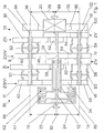
- Fig. 1 shows a change-speed gearbox, wherein an input shaft 10 with a differential gear 20 through a first and a second partial transmission 78, 80 connected in the Power flow are arranged parallel to each other. Every partial transmission 78, 80 has a frictional power shift clutch K1, K2 and an intermediate shaft 12, 14 which are concentric with each other and are arranged coaxially with the input shaft 10, wherein in each case the intermediate shaft 12, 14 via the power shift clutch K1, K2 with the input shaft 10 can be operatively connected. On each intermediate shaft 12, 14 are each three fixed wheels 34, 58, 60, 38, 62, 64 stored.
- a second Output shaft 18 is arranged in addition to a parallel to the intermediate waves 12, 14 arranged first output shaft 16 in parallel.
- the second output shaft 18 has starting from its central axis 86 an axis distance 24th to the central axis 82 of the input shaft 10 and the intermediate shafts 12, 14, which is smaller than an axial distance 22 starting from a central axis 84 of the first output shaft 16 to the central axis 82 ( Figures 1 and 4). 4, the center axes 82, 84, 86 and the axial distances 22, 24 in a side view schematically shown.
- the center axes 84, 86 of the output shafts 16, 18 have a same axial distance 26 to a central axis 88 of the differential gear 20th
- the fixed gear 34 on the intermediate shaft 14 meshes with both a on the first output shaft 16 concentrically and rotatably mounted Idler gear 42 as well as with one on the second output shaft 18 concentric and rotatably mounted idler gear 50th
- the fixed gear 38 meshes with the intermediate shaft 12 both with a on the first output shaft 16 concentrically and rotatably mounted Idler gear 46 as well as with one on the second output shaft 18 concentric and rotatably mounted idler gear 54th
- 24 may be a gear level ZIII / VI with the fixed gear 34 and the loose wheels 42, 50th and a gear level ZII / IV with the fixed gear 38 and the loose wheels 46, 54 each two gears III, VI, II, IV assigned become.
- Fig. 5 is the change-speed gearbox from Fig. 1 with changed axis distances 28, 30, 32 shown.
- the output shafts 16, 18 have starting from their central axes 84, 86 a same axial distance 28th to the central axis 82 of the input shaft 10 and the intermediate shafts 12, 14 and different axis distances 30, 32 to the central axis 88 of the differential gear 20.
- the axis distances 30, 32 are chosen so that, as in the embodiment in Fig. 1 in the gear level ZII / IV a step jump from the second in the fourth gear II-IV results, the one increment from the third to the sixth gear III-VI, which the gear level ZIII / VI is assigned.
- the idler gear 42 meshes with the gear level ZIII / VI with the on the Intermediate shaft 14 mounted fixed gear 34 and is the third gear Assigned to III.
- the idler gear 90 meshes in a gear level ZI with the mounted on the intermediate shaft 14 fixed gear 58 and is assigned to the first gear I.
- 90 is a gear coupling S1 arranged in the third gear III, the idler gear 42 and the first gear I the idler gear 90 with the output shaft 16 couples.
- the idler gear 46 meshes with the gear level ZII / IV with the on the Intermediate shaft 12 mounted fixed gear 38 and is the second gear II assigned. That assigned to the reverse gear R Idler gear 92 meshes in a gear plane ZR with a not shown gear for turning inversion, which in turn meshes with the fixed gear 62 on the intermediate shaft 12. Between the loose wheels 46, 92 a gear clutch S2 is arranged, in the second gear II, the idler gear 46 and the reverse gear R the idler gear 92 with the output shaft 16 couples.
- the fixed wheel 94 drives directly with a fixed translation a gear 96 of the differential gear 20 from.
- the first and the second gear I, II are arranged on the output shaft 16. When changing gear from the first to the second gear I-II is always driven off via the output shaft 16. On Changing the output shafts 16, 18 is avoided and it can a high level of comfort can be achieved.
- idler gear 50 In addition to the idler gear 50 are on the output shaft 18 three more concentric and rotatably mounted idler gears 98, 54, 100 and a concentric and rotatably mounted fixed gear 102 arranged.
- the idler gear 50 meshes in the gear level ZIII / VI with the on the Intermediate shaft 14 mounted fixed gear 34 and is the sixth gear VI assigned.
- the idler gear 98 meshes in a gear level ZIV with the mounted on the intermediate shaft 14 fixed gear 60 and is assigned to the fourth gear IV.
- a gear clutch S3 is arranged in the sixth gear VI, the idler gear 50 and the fourth gear IV, the idler gear 98 with the output shaft 18 couples.
- the idler gear 54 meshes in the gear level ZII / IV with the on the Intermediate shaft 12 mounted fixed gear 38 and is the fourth gear IV assigned.
- the idler gear 100 meshes in a gear level ZV with the mounted on the intermediate shaft 12 fixed gear 64 and is assigned to the fifth gear V.
- a gear clutch S4 is arranged, the in the fourth gear IV, the idler gear 54 and the fifth gear V the idler gear 100 with the output shaft 18 couples.
- the Festrad 102 drives directly with a fixed translation on Gear 96 of the differential gear 20 from.
- From the second gear II can under load by an overlap control the first power-shift clutch K1 to the second Powershift clutch K2 in the fourth gear IV in the Gear level ZIV can be switched and accordingly from the fourth gear IV in the second gear II under Load to be switched back.
- double upshifts and double downshifts by a crossover control the power shift clutches K1, K2 between the third and the fifth gear III-V and between the fourth gear IV in the gear level ZII / IV and the sixth gear VI possible under load.
- All transmissions I-VI can be under load through an overlap control be switched sequentially.
- Fig. 2 a variant of FIG. 1 is shown, in which the input shaft 10 with the differential gear 20 by a first and a second partial transmission 110, 112 is connected, the are arranged parallel to each other in the power flow.
- Essentially Consistent components are basically the same Numbered. The following are the special features of the embodiment in Fig. 2 in comparison to the Embodiment in Fig. 1 described in more detail. In terms of Consistent details and features can be found on the description Reference is made to the embodiment in Fig. 1.
- the change-speed gearbox has on each intermediate shaft 12, 14 each only two concentric and rotatably mounted Fixed wheels 34, 66, 38, 68.
- the gear levels ZI, ZIV, ZR, ZV of the embodiment in Fig. 1 has the change-speed gearbox in Fig. 2 next to the gear levels ZIII / VI and ZII / IV the gear level ZR / I and ZVa and thus two gear levels less than the change-speed gearbox in Fig. 1.
- the gear change transmission in Fig. 2 can be particularly short, easy and inexpensive to run.
- gear level ZR / I In the gear level ZR / I, between the gear levels ZIII / VI and ZII / IV is arranged, that meshes on the intermediate shaft 14 mounted fixed gear 66 with a not shown Gear for turning inversion, which in turn with a concentric and idler gear rotatably mounted on the output shaft 16 104 combs.
- the idler gear 104 is associated with the reverse gear R. and is connected to the output shaft 16 through the gear coupling S1 detachable.
- the fixed gear 66 meshes in the gear level ZR / I concentric with one on the output shaft 18 and rotatably mounted idler gear 106.
- the first gear I associated idler gear 106 is connected through the gear coupling S3 with the Output shaft 18 can be coupled.
- From the first to the fourth gear I-IV can easily apparently sequentially by means of an overlap control the two power shift clutches K1, K2 upshifted under load become.
- From the fourth to the fifth gear IV-V can either with load interruption or advantageously by interposing of the sixth gear VI via the power shift clutch K2 for generating a filling torque also below Load to be switched.
- the gear change from the fifth gear V in the sixth gear VI is in turn by a Overlapping control of the power shift clutches K1, K2 feasible.
- According to the sequential upshift of the first one in the sixth gear I-VI can be sequentially under load switched back from the sixth to the first gear VI-I become.
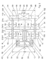
- Fig. 3 shows a variant of FIG. 1, wherein the input shaft 10 by a first and a second partial transmission 114, 116th is connected to the differential gear 20 in the power flow are arranged parallel to each other.
- Essentially consistent Components are again with the same reference numerals quantified. Below are the specifics of the embodiment in Fig. 3 in comparison to the embodiment in Fig. 1 described in more detail. Regarding consistent Details and features may be found in the description of the embodiment be referenced in Fig. 1.
- two fixed wheels 36, 74 are concentric and rotationally fixed and on the intermediate shaft 12 are a loose wheel 40 concentric and rotatable and two fixed wheels 70, 72 concentric and rotatably mounted.
- the second output shaft 18 has, starting from its central axis 86, an axial distance 120 from the central axis 82 of the input shaft 10 and the intermediate shafts 12, 14, which is smaller than an axial distance 118 from the central axis 84 of the first output shaft 16 to the central axis 82.
- the fixed gear 36 on the intermediate shaft 14 meshes with both on the first output shaft 16 concentrically and rotatably mounted idler gear 44 and a concentrically and rotatably mounted on the second output shaft 18 idler gear 52.
- the idler gear 74 meshes with a on the output shaft 18 concentric and rotatably mounted idler gear 122 and with a gear, not shown, for reversing the rotational direction, which in turn meshes with a on the output shaft 16 concentrically and rotatably mounted idler gear 124. Further, the idler gear 40 meshes on the intermediate shaft 12 both with a on the first output shaft 16 concentrically and rotatably mounted idler gear 48 and a concentric and rotatably mounted on the second output shaft 18 idler gear 56.
- the axis distances 118, 120 are chosen so that in the Gear level ZIII / IV one increment from the third to the fourth Transmission III-IV results in a step change from fourth corresponds to the sixth gear IV-VI, which the Gear level ZIV / VI is assigned.
- the idler gear 44 On the output shaft 16 are next to the idler gear 44 another three concentric and rotatably mounted idler gears 124, 48, 126 and a concentric and rotatably mounted fixed gear 128 arranged.
- the arranged in the gear level ZIV / VI idler gear 44 is associated with the fourth gear IV and is connected to a gear coupling S5 with the output shaft 16 can be coupled.
- the arranged in the gear level ZR / II idler gear 124 is the Reverse gear R assigned and that in the gear level ZIII / IV arranged idler gear 48 is the third gear III assigned. Between the idler gears 124 and 48 is a gear clutch S6 arranged in the reverse gear R, the idler gear 124 and the third gear III, the idler gear 48 with the Output shaft 16 couples.
- the idler gear 126 meshes with the fixed gear in a gear plane ZVb 72 on the intermediate shaft 12, the fifth gear V is assigned and is connected to a gear coupling S7 with the output shaft 16 detachable.
- the Festrad 128 drives directly with a fixed translation to the gear 96 of the differential gear 20 off.
- idler gear 52 In addition to the idler gear 52 are on the output shaft 18 three more concentric and rotatably mounted idler gears 122, 56, 76 and a concentric and rotatably mounted fixed gear 130 arranged.
- the arranged in the gear level ZIV / VI idler gear 52 is the assigned to sixth gear VI. That in the gear level ZR / II arranged idler gear 122 is the second gear II assigned.
- a gear coupling S8 disposed in the sixth gear VI the Idler gear 52 and in the second gear II, the idler gear 122 with the Output shaft 18 couples.
- the arranged in the gear level ZIII / IV idler gear 56 is the Fourth gear IV assigned.
- the idler gear 76 meshes in one Gear level ZIb with the mounted on the intermediate shaft 12 Fixed gear 70 and is assigned to the first gear I.
- a gear coupling S9 is arranged, in the fourth gear IV, the idler gear 56 and in the first gear I the idler gear 76 with the output shaft 18th couples.
- the fixed wheel 130 drives directly with a fixed translation on the gear 96 of the differential gear 20 from.
- the first and the second gear I, II are on the output shaft 18 arranged.
- changing gear from the first to the second gear I-II is always on the output shaft 18th abortion.
- a change of the output shafts 16, 18 is avoided and a high level of comfort can be achieved.
- the stored in the gear level ZIII / IV on the intermediate shaft 12 Losrad 40 can with a gear coupling S10 with the intermediate shaft 14 coupled and with the power shift clutch K2 in Active compound are brought. Furthermore, the idler gear 40 with a gear clutch S11 coupled to the intermediate shaft 12 and brought into operative connection with the power-shift clutch K1 become.
- the third gear III assigned idler gear 48 and assigned to the fourth gear IV Losrad 56 can each with both closed power shift clutch K1 and driven off with closed power shift clutch K2 become. It can be sequential from the first to the sixth gear I-VI by an overlap control of the power shift clutches K1, K2 upshifted under load and sequential by an overlap control of the power shift clutches K1, K2 are switched back under load.
- Gear shafts S10, S11 can be used for intermediate shafts 12, 14 are brought into operative connection with each other, namely by the gear coupling S10, the idler gear 40 with the intermediate shaft 14 and the gear coupling S11, the idler gear 40 with the intermediate shaft 12 couples. It can over the first power shift clutch K1, the intermediate shaft 12, the gear coupling S11, the Idler gear 40, the gear coupling S10 on the intermediate shaft 14 and be driven off via the fixed wheels 74 and 36. Furthermore, can via the second power shift clutch K2, via the intermediate shaft 14, the gear clutch S10, the idler gear 40, the gear clutch S11 abraded to the intermediate shaft 12 and the fixed wheels 70, 72 become.
- the gear coupling S9, the idler gear 76 with the output shaft 18th Der Power flow extends from the input shaft 10 via the first Power shift clutch K1, the intermediate shaft 12, the fixed gear 70, the idler gear 76, the gear clutch S9, the output shaft 18 and via the fixed gear 130 to the differential gear 20 and from the Input shaft 10 via the second power-shift clutch K2, the Intermediate shaft 14, the gear clutch S10, the idler gear 40, the Gear coupling S11, the intermediate shaft 12, the fixed gear 70, the Idler gear 76, the gear clutch S9, the output shaft 18 and over the fixed gear 130 to the differential gear 20. decreases the differential speed in the power shift clutches K1, K2 to zero, the power-shift clutch K2 is opened.
- an output shaft is advantageous to the fourth, the fifth and the sixth gear and an output shaft the first, second and third gears and the reverse gear, wherein the Gear level for the third and sixth gear, one Gear level for the first gear and a gear level for the fourth gear each a gear on the one Intermediate shaft and the gear level for the second and fourth Transmission gear, a gear level for the fifth gear and a gear plane for the reverse gear each one Have gear on the other intermediate shaft.
- An output shaft is advantageous to the second, the third, the fifth gear and the reverse gear and an output shaft of the first, the fourth and the sixth gear assigned, the gear level for the third and sixth gear and a gear level for the reverse gear and the first gear each a gear on the one intermediate shaft and the gear level for the second and fourth gear and a gear level for the fifth gear each have a gear on the other intermediate shaft respectively.
- a gear level the third and fourth GeZahnrad the gear level is with the first and the second Power shift clutch operatively engageable.
- an output shaft to the first, the second, the fourth and the sixth gear and the other Output shaft of the third, the fourth and the fifth gear and the reverse gear wherein a gear level for the fourth and sixth gear and a gear level for the reverse gear and the second Gear each gear on the one intermediate shaft and a gear level for the third and fourth gears, a gear level for the first gear and a gear level for the fifth gear each have a gear on the have other intermediate shaft.
Landscapes
- Engineering & Computer Science (AREA)
- General Engineering & Computer Science (AREA)
- Mechanical Engineering (AREA)
- Structure Of Transmissions (AREA)
- Retarders (AREA)
- General Details Of Gearings (AREA)
- Transmission Devices (AREA)
- Arrangement And Driving Of Transmission Devices (AREA)
- Mechanical Coupling Of Light Guides (AREA)
Abstract
Description
- Fig. 1
- eine schematische Darstellung eines Zahnräderwechselgetriebes, bei dem zwei Abtriebswellen unterschiedliche Achsenabstände zu zwei Zwischenwellen aufweisen,
- Fig. 2
- eine Variante nach Fig. 1 mit vier Zahnradebenen,
- Fig. 3
- eine schematische Darstellung eines Zahnräderwechselgetriebes, bei dem zwei Zwischenwellen über Schaltelemente verbindbar sind,
- Fig. 4
- eine schematische Seitenansicht des Zahnräderwechselgetriebes nach Fig. 1 und
- Fig. 5
- eine schematische Seitenansicht einer Variante nach Fig. 1.
Das Festrad 36 auf der Zwischenwelle 14 kämmt sowohl mit einem auf der ersten Abtriebswelle 16 konzentrisch und drehbar gelagerten Losrad 44 als auch mit einem auf der zweiten Abtriebswelle 18 konzentrisch und drehbar gelagerten Losrad 52. Das Losrad 74 kämmt mit einem auf der Abtriebswelle 18 konzentrisch und drehbar gelagerten Losrad 122 und mit einem nicht näher dargestellten Zahnrad zur Drehsinnumkehr, das wiederum mit einem auf der Abtriebswelle 16 konzentrisch und drehbar gelagerten Losrad 124 kämmt. Ferner kämmt das Losrad 40 auf der Zwischenwelle 12 sowohl mit einem auf der ersten Abtriebswelle 16 konzentrisch und drehbar gelagerten Losrad 48 als auch mit einem auf der zweiten Abtriebswelle 18 konzentrisch und drehbar gelagerten Losrad 56. Durch die unterschiedlichen Achsenabstände 118, 120 kann eine Zahnradebene ZIV/VI mit dem Festrad 36 und den Losrädern 44, 52, eine Zahnradebene ZR/II mit dem Festrad 74 und den Losrädern 122, 124 und eine Zahnradebene ZIII/IV mit den Losrädern 40, 48, 56 jeweils zwei Getriebegängen IV, VI, R, II, III, IV zugeordnet werden.
Claims (12)
- Zahnräderwechselgetriebe, bei dem eine Eingangswelle mit einem Differentialgetriebe durch ein erstes und ein zweites Teilgetriebe verbunden ist, die im Kraftfluß parallel zueinander angeordnet sind und je eine reibschlüssige Lastschaltkupplung und je eine Zwischenwelle aufweisen, die zueinander konzentrisch und koaxial zur Eingangswelle angeordnet sind, wobei jeweils die Zwischenwelle über die Lastschaltkupplung mit der Eingangswelle wirkungsmäßig verbindbar ist, und mit zumindest einem Zahnrad je Zwischenwelle, von denen zumindest eine mit einer parallel zu den Zwischenwellen angeordneten ersten Abtriebswelle wirkungsmäßig verbindbar ist, die direkt oder indirekt auf das Differentialgetriebe abtreibt, wobei parallel zur ersten Abtriebswelle (16) zumindest eine zweite Abtriebswelle (18) angeordnet ist, die zu den Zwischenwellen (12, 14) und/oder zu dem Differentialgetriebe (20) einen von der ersten Abtriebswelle (16) abweichenden Achsenabstand (22, 24, 30, 32, 118, 120) aufweist, und zumindest ein Zahnrad (34, 36, 38, 40) wenigstens einer Zwischenwelle (12, 14) sowohl mit einem Zahnrad (42, 44, 46, 48) auf der ersten Abtriebswelle (16) als auch mit einem Zahnrad (50, 52, 54, 56) auf der zweiten Abtriebswelle (18) kämmt, (ursprünglicher Anspruch 1)
wobei zumindest ein Zahnrad auf einer Zwischenwelle zwei Getriebegängen zugeordnet ist, (ursprünglich Seite 4, Abs. 3)
dadurch gekennzeichnet, dass der erste und der zweite Getriebegang (I, II) auf einer gemeinsamen Abtriebswelle (16, 18) angeordnet sind. (ursprünglicher Anspruch 3) - Zahnräderwechselgetriebe nach Patentanspruch 1,
dadurch gekennzeichnet, dass der erste und der zweite Getriebegang (I, II) auf einer gemeinsamen Abtriebswelle (16 bzw. 18) angeordnet sind, so dass beim Gangwechsel vom ersten (I) in den zweiten Getriebegang (II) über die gleiche Abtriebswelle (16 bzw. 18) abgetrieben werden kann, wobei ein Wechsel der Abtriebswellen (16, 18) vermieden werden kann und dadurch der Komfort für den meist unter hoher Last stattfindenden Gangwechsel vom ersten (I) in den zweiten (II) Getriebegang gesteigert werden kann. (ursprünglich Seite 4, Abs. 4ff.) - Zahnräderwechselgetriebe nach einem der vorhergehenden Patentansprüche,
dadurch gekennzeichnet, dass innerhalb der einen Zwischenwelle (14) die axial über diese hinausragende zweite Zwischenwelle (12) angeordnet ist, wobei der axial über die eine Zwischenwelle (14) hinausragende Bereich der zweiten Zwischenwelle (12)trägt. (ursprüngliche Zeichnung Fig. 1 bis Fig. 3)mehrere axial benachbarte Zahnräder (38, 62, 64 bzw. 38, 68 bzw. 40, 70, 72) undan dessen axialem Ende das Festrad eines fünften Getriebegangs (V) - Zahnräderwechselgetriebe nach einem der vorhergehenden Patentansprüche,
dadurch gekennzeichnet, dass innerhalb der einen Zwischenwelle (14) die axial über diese hinausragende zweite Zwischenwelle (12) gelagert ist. (ursprüngliche Zeichnung Fig. 1 bis Fig. 3) - Zahnräderwechselgetriebe nach einem der vorhergehenden Patentansprüche,
dadurch gekennzeichnet, dass ein Losrad (100) in einer Zahnradebene (ZV) mit dem auf der Zwischenwelle (12) gelagerten Festrad (64) kämmt und dem fünften Getriebegang (V) zugeordnet ist. (ursprünglich Seite 12, Abs. 2) - Zahnräderwechselgetriebe nach einem der vorhergehenden Patentansprüche,
dadurch gekennzeichnet, dass einer Zahnradebene (ZVb) des fünften Getriebegangs unmittelbar benachbart eine Zahnradebene (ZIb) des ersten Getriebegangs folgt, welcher
unmittelbar benachbart eine Zahnradebene (ZIII) des dritten Getriebegangs (III) folgt, wobei diese drei Zahnradebenen in dem axial über die eine Zwischenwelle (14) hinausragende Bereich der zweiten Zwischenwelle (12) liegen und wobei im axialen Bereich der einen Zwischenwelle (14) der zweite und sechste Getriebegang (II, VI) liegen. (ursprünglich Fig. 3) - Zahnräderwechselgetriebe nach einem der vorhergehenden Patentansprüche,
dadurch gekennzeichnet, dass ein Losrad des fünften Getriebeganges auf der ersten Abtriebswelle (16 bzw. 18) gelagert ist, wohingegen das Losrad des ersten Getriebeganges auf der zweiten Abtriebswelle (18 bzw. 16) gelagert ist. (ursprünglich Fig. 1 bis 3) - Zahnräderwechselgetriebe nach Patentanspruch 7,
dadurch gekennzeichnet, dass auf der den Lastschaltkupplungen (K1, K2) zugewandten Seitedes Losrades des fünften Getriebeganges (V) unddes Losrades des ersten Getriebeganges (I) jeweils eine Zahnradkupplung (S4, S1 bzw. S2, S3 bzw. S7, S9) zur Kopplung dieses Losrades mit dessen Abtriebswelle (16 bzw. 18) angeordnet ist. (ursprünglich Fig. 1 bis Fig. 3) - Zahnräderwechselgetriebe nach einem der vorhergehenden Ansprüche,
dadurch gekennzeichnet, dass die zweite Zwischenwelle (12) innerhalb der ersten Zwischenwelle (14) mittels zwei axial benachbarten Lagern gelagert ist. (ursprünglich Fig. 1 bis Fig. 3) - Zahnräderwechselgetriebe nach einem der vorhergehenden Patentansprüche,
dadurch gekennzeichnet, dass die Lastschaltkupplungen (K1, K2) unterschiedlich für verschiedene Anfahrvorgänge ausgelegt sind und/oder einzeln zum Anfahren aus einem höheren Getriebegang genutzt werden. (ursprünglich Seite 7, Abs. 3) - Zahnräderwechselgetriebe nach einem der vorhergehenden Patentansprüche,
dadurch gekennzeichnet, dass die Losräder (90, 46, 42) des ersten Getriebeganges (I), des zweiten Getriebeganges (II) und des dritten Getriebeganges (III) koaxial auf der ersten Abtriebswelle (16) angeordnet sind. (ursprünglich Fig. 1) - Zahnräderwechselgetriebe nach einem der vorhergehenden Patentansprüche,
dadurch gekennzeichnet, dass die Losräder (100, 50) des fünften Getriebeganges (V) und des sechsten Getriebeganges (VI) koaxial auf der zweiten Abtriebswelle (18) angeordnet sind (ursprünglich Fig. 1)
Applications Claiming Priority (5)
| Application Number | Priority Date | Filing Date | Title |
|---|---|---|---|
| DE19860251A DE19860251C1 (de) | 1998-12-24 | 1998-12-24 | Zahnräderwechselgetriebe mit zwei Teilgetrieben mit je einer Lastschaltkupplung |
| DE19860251 | 1998-12-24 | ||
| DE1999123185 DE19923185A1 (de) | 1999-05-20 | 1999-05-20 | Zahnräderwechselgetriebe mit zwei im Kraftfluß parallel zueinander angeordneten Teilgetrieben |
| DE19923185 | 1999-05-20 | ||
| EP99125458A EP1013965B1 (de) | 1998-12-24 | 1999-12-21 | Zahnräderwechselgetriebe mit zwei im Kraftfluss parallel zueinander angeordneten Teilgetrieben |
Related Parent Applications (1)
| Application Number | Title | Priority Date | Filing Date |
|---|---|---|---|
| EP99125458A Division EP1013965B1 (de) | 1998-12-24 | 1999-12-21 | Zahnräderwechselgetriebe mit zwei im Kraftfluss parallel zueinander angeordneten Teilgetrieben |
Publications (3)
| Publication Number | Publication Date |
|---|---|
| EP1367293A2 true EP1367293A2 (de) | 2003-12-03 |
| EP1367293A3 EP1367293A3 (de) | 2004-02-04 |
| EP1367293B1 EP1367293B1 (de) | 2005-10-05 |
Family
ID=26051061
Family Applications (3)
| Application Number | Title | Priority Date | Filing Date |
|---|---|---|---|
| EP03019572A Expired - Lifetime EP1367293B1 (de) | 1998-12-24 | 1999-12-21 | Zahnräderwechselgetriebe mit zwei im Kraftfluss parallel zueinander angeordneten Teilgetrieben |
| EP03019573A Expired - Lifetime EP1367294B1 (de) | 1998-12-24 | 1999-12-21 | Zahnräderwechselgetriebe mit zwei im Kraftfluss parallel zueinander angeordneten Teilgetrieben |
| EP99125458A Expired - Lifetime EP1013965B1 (de) | 1998-12-24 | 1999-12-21 | Zahnräderwechselgetriebe mit zwei im Kraftfluss parallel zueinander angeordneten Teilgetrieben |
Family Applications After (2)
| Application Number | Title | Priority Date | Filing Date |
|---|---|---|---|
| EP03019573A Expired - Lifetime EP1367294B1 (de) | 1998-12-24 | 1999-12-21 | Zahnräderwechselgetriebe mit zwei im Kraftfluss parallel zueinander angeordneten Teilgetrieben |
| EP99125458A Expired - Lifetime EP1013965B1 (de) | 1998-12-24 | 1999-12-21 | Zahnräderwechselgetriebe mit zwei im Kraftfluss parallel zueinander angeordneten Teilgetrieben |
Country Status (6)
| Country | Link |
|---|---|
| US (1) | US6209407B1 (de) |
| EP (3) | EP1367293B1 (de) |
| AT (3) | ATE303533T1 (de) |
| DE (3) | DE59912628D1 (de) |
| ES (3) | ES2326567T3 (de) |
| PT (1) | PT1013965E (de) |
Cited By (1)
| Publication number | Priority date | Publication date | Assignee | Title |
|---|---|---|---|---|
| FR2880090A1 (fr) * | 2004-12-29 | 2006-06-30 | Renault Sas | Boite de vitesses compacte a deux embrayages |
Families Citing this family (67)
| Publication number | Priority date | Publication date | Assignee | Title |
|---|---|---|---|---|
| DE10102028A1 (de) * | 2000-02-15 | 2001-08-16 | Luk Lamellen & Kupplungsbau | Drehmomentübertragungsvorrichtung, insbesondere mit Doppelkupplungsgetriebe |
| DE10191985D2 (de) * | 2000-05-17 | 2003-07-03 | Luk Lamellen & Kupplungsbau | Getriebe mit Kupplung sowie Verfahren zum Betreiben einer Kupplung |
| US6490945B2 (en) | 2001-01-10 | 2002-12-10 | New Venture Gear, Inc. | Twin clutch automated transmission with integrated transfer case |
| US6499370B2 (en) | 2001-01-10 | 2002-12-31 | New Venture Gear, Inc. | Twin clutch automated transaxle with motor/generator synchronization |
| US6427549B1 (en) * | 2001-01-10 | 2002-08-06 | New Venture Gear, Inc. | Dual countershaft twin clutch automated transmission |
| US6460425B1 (en) | 2001-01-10 | 2002-10-08 | New Venture Gear, Inc. | Twin clutch automated transmission |
| US6397994B1 (en) | 2001-01-10 | 2002-06-04 | New Venture Gear, Inc. | Powershift transmission with engine clutch assembly |
| US6427550B1 (en) | 2001-01-12 | 2002-08-06 | New Venture Gear, Inc. | Twin clutch automated transaxle |
| US6427547B1 (en) | 2001-02-08 | 2002-08-06 | New Venture Gear, Inc. | Dual-countershaft twin-clutch automated transmission with bi-directional clutches |
| DE10209514B4 (de) | 2001-03-30 | 2016-06-09 | Schaeffler Technologies AG & Co. KG | Antriebsstrang |
| US6575866B2 (en) | 2001-04-09 | 2003-06-10 | New Venture Gear, Inc. | Hybrid drive system for motor vehicle with powershift transmission |
| JP2003139204A (ja) * | 2001-10-31 | 2003-05-14 | Aichi Mach Ind Co Ltd | 変速機 |
| FR2847013B1 (fr) * | 2002-11-08 | 2005-07-15 | Renault Sa | Boite de vitesse compacte a deux embrayages et a marche arriere par le pignon de premiere |
| DE10253259A1 (de) * | 2002-11-15 | 2004-05-27 | Zf Friedrichshafen Ag | Universell gestaltbares Kraftfahrzeuggetriebe |
| DE10305241A1 (de) * | 2003-02-08 | 2004-09-23 | Zf Friedrichshafen Ag | Sechs- oder siebengängiges Doppelkupplungsgetriebe |
| DE10305242A1 (de) * | 2003-02-08 | 2004-09-23 | Zf Friedrichshafen Ag | Sechs- oder siebengängiges Schaltgetriebe für ein Kraftfahrzeug |
| US6869382B2 (en) * | 2003-05-07 | 2005-03-22 | Daimlerchrysler Corporation | Double-downshift gear strategy for a dual clutch automatic transmission |
| DE10325647A1 (de) * | 2003-06-06 | 2004-02-05 | Daimlerchrysler Ag | Doppelkupplungsgetriebe |
| FR2859004B1 (fr) * | 2003-08-19 | 2005-12-30 | Renault Sa | Boite de vitesses compacte a sept rapports de marche avant |
| KR100569140B1 (ko) * | 2003-12-10 | 2006-04-07 | 현대자동차주식회사 | 이중 클러치 변속기 |
| DE102004010806A1 (de) * | 2004-03-05 | 2005-09-22 | Daimlerchrysler Ag | Doppelkupplungsgetriebe |
| DE102004012909A1 (de) * | 2004-03-17 | 2005-10-06 | Daimlerchrysler Ag | Doppelkupplungsgetriebe |
| CN100460717C (zh) * | 2004-05-17 | 2009-02-11 | 通用汽车公司 | 用于从动力源传递动力的多速传动装置及动力系 |
| DE102004049832B4 (de) * | 2004-10-13 | 2016-09-29 | Daimler Ag | Doppelkupplungsgetriebe |
| DE102004056936B4 (de) * | 2004-11-23 | 2011-02-03 | Getrag Getriebe- Und Zahnradfabrik Hermann Hagenmeyer Gmbh & Cie Kg | Stufenwechselgetriebe für ein Kraftfahrzeug |
| US7246536B2 (en) * | 2005-03-17 | 2007-07-24 | Ford Global Technologies, Llc | Dual clutch kinematic arrangements with wide span |
| GB0510129D0 (en) * | 2005-05-18 | 2005-06-22 | Zeroshift Ltd | Sequential hub layout |
| DE102005057802B4 (de) * | 2005-12-03 | 2014-02-13 | Daimler Ag | Doppelkupplungsgetriebe |
| JP4380660B2 (ja) * | 2006-05-30 | 2009-12-09 | 三菱自動車工業株式会社 | ダブルクラッチ変速機 |
| US7743677B2 (en) * | 2006-08-23 | 2010-06-29 | Gm Global Technology Operations, Inc. | Powertrain with torque converter and axially compact seven speed dual clutch transmission |
| GB0617365D0 (en) * | 2006-09-02 | 2006-10-11 | Bamford Excavators Ltd | Gear shift mechanism |
| GB2442481B (en) * | 2006-10-03 | 2011-03-09 | Bamford Excavators Ltd | Method of controlling a vehicle transmission |
| GB2445568B (en) * | 2006-10-03 | 2011-06-08 | Bamford Excavators Ltd | Method for controlling a vehicle transmission |
| GB0623292D0 (en) * | 2006-11-22 | 2007-01-03 | Zeroshift Ltd | Transmission system |
| US7870804B2 (en) * | 2006-12-08 | 2011-01-18 | GM Global Technologies Operations LLC | Multi-speed dual clutch transmission |
| US7752934B2 (en) * | 2007-02-20 | 2010-07-13 | Gm Global Technology Operations, Inc. | Multi speed transmission having a countershaft gearing arrangement |
| US7703346B2 (en) * | 2007-02-22 | 2010-04-27 | Gm Global Technology Operations, Inc. | Multi-speed transmission with countershaft gearing |
| US7610825B2 (en) * | 2007-02-22 | 2009-11-03 | Gm Global Technology Operations, Inc. | Multi-speed transmission with countershaft gearing |
| US7644639B2 (en) | 2007-02-23 | 2010-01-12 | Gm Global Technology Operations, Inc. | Multi-speed transmission with countershaft gearing |
| US7640818B2 (en) | 2007-02-23 | 2010-01-05 | Gm Global Technology Operations, Inc. | Multi-speed transmission with a countershaft gearing |
| GB0714320D0 (en) * | 2007-07-23 | 2007-08-29 | Jcb Transmissions | Vehicle transmission |
| EP2055989B1 (de) * | 2007-10-29 | 2010-12-15 | Ford Global Technologies, LLC | Doppelkupplungsgetriebe |
| DE102007000595B4 (de) * | 2007-10-30 | 2020-07-09 | Zf Friedrichshafen Ag | Lastschaltbares Parallelschaltgetriebe und Doppelkupplungsgetriebe |
| US8056429B2 (en) * | 2008-04-02 | 2011-11-15 | GM Global Technology Operations LLC | Multi-speed dual clutch transmission with countershaft gearing arrangement |
| DE102008001407A1 (de) * | 2008-04-28 | 2009-10-29 | Zf Friedrichshafen Ag | Mehrgruppengetriebe eines Kraftfahrzeuges |
| DE102008024633A1 (de) | 2008-05-21 | 2008-09-18 | Daimler Ag | Doppelkupplungsgetriebe |
| DE102008034607A1 (de) * | 2008-07-25 | 2010-01-28 | Voith Patent Gmbh | Überlagerungsgetriebe mit Kopplungswellen |
| US7987740B2 (en) * | 2008-09-03 | 2011-08-02 | GM Global Technology Operations LLC | Multi-speed transmission with countershaft gearing arrangement |
| US8434380B2 (en) * | 2009-01-23 | 2013-05-07 | GM Global Technology Operations LLC | Dual clutch multi-speed transmission |
| US8266977B2 (en) * | 2009-04-03 | 2012-09-18 | GM Global Technology Operations LLC | Seven speed dual clutch transmission |
| US8495926B2 (en) * | 2009-04-22 | 2013-07-30 | GM Global Technology Operations LLC | Dual clutch transmission |
| US9249863B2 (en) * | 2009-04-22 | 2016-02-02 | Gm Global Technology Operations, Llc | Dual clutch transmission |
| US8573084B2 (en) * | 2009-04-22 | 2013-11-05 | GM Global Technology Operations LLC | Dual clutch transmission |
| US8528431B2 (en) * | 2009-04-28 | 2013-09-10 | GM Global Technology Operations LLC | Dual clutch transmission |
| US9625006B2 (en) | 2010-03-01 | 2017-04-18 | GM Global Technology Operations LLC | Seven speed dual clutch transmission |
| EP2669547A4 (de) * | 2011-01-28 | 2016-04-06 | Univance Corp | Fahrzeuggetriebe mit doppelkupplung |
| GB201109100D0 (en) | 2011-05-27 | 2011-07-13 | Zeroshift Ltd | Transmission system |
| CN102678842B (zh) * | 2011-12-08 | 2014-08-13 | 河南科技大学 | 一种多挡拖拉机中使用的双离合器变速器 |
| DE102011088605B4 (de) | 2011-12-14 | 2021-02-18 | Zf Friedrichshafen Ag | Doppelkupplungsgetriebe |
| DE102011088593B4 (de) * | 2011-12-14 | 2021-01-28 | Zf Friedrichshafen Ag | Doppelkupplungsgetriebe |
| JP5439555B2 (ja) * | 2012-08-08 | 2014-03-12 | 富士重工業株式会社 | 変速機 |
| JP5545778B2 (ja) * | 2012-08-08 | 2014-07-09 | 富士重工業株式会社 | 変速機 |
| KR101334508B1 (ko) * | 2012-10-31 | 2013-11-29 | 현대 파워텍 주식회사 | 더블 클러치 변속기 구조 |
| KR101500354B1 (ko) * | 2013-07-24 | 2015-03-09 | 현대자동차 주식회사 | 차량용 변속장치 |
| US10274051B2 (en) * | 2015-12-30 | 2019-04-30 | GM Global Technology Operations LLC | Multi-speed dual clutch transmission |
| TWI644041B (zh) | 2017-10-20 | 2018-12-11 | 財團法人工業技術研究院 | 雙軸離合變速裝置 |
| CN117432780B (zh) * | 2023-12-18 | 2024-03-15 | 中国第一汽车股份有限公司 | 纵置变速器、机电混合系统及车辆 |
Citations (2)
| Publication number | Priority date | Publication date | Assignee | Title |
|---|---|---|---|---|
| US4461188A (en) | 1981-12-23 | 1984-07-24 | Ford Motor Company | Dual clutch multiple countershaft transmission |
| US4658663A (en) | 1984-03-30 | 1987-04-21 | Nissan Motor Co., Ltd. | Synchromesh transmission suited for use as automotive automatic transmission |
Family Cites Families (18)
| Publication number | Priority date | Publication date | Assignee | Title |
|---|---|---|---|---|
| DE720884C (de) * | 1936-10-22 | 1942-05-18 | Getriebe G M B H Deutsche | Sechs- und mehrgaengiges Zahnraederwechselgetriebe fuer Vor- und Rueckwaertslauf |
| US2599801A (en) * | 1949-06-11 | 1952-06-10 | Borg Warner | Double countershaft transmission |
| US2658405A (en) * | 1950-12-29 | 1953-11-10 | Adiel Y Dodge | Selective gear transmission |
| JPS58118355A (ja) * | 1982-01-08 | 1983-07-14 | Nissan Motor Co Ltd | 車両用変速機 |
| SE451005B (sv) * | 1985-03-28 | 1987-08-24 | Volvo Ab | Motorfordonsvexellada |
| EP0268582B1 (de) * | 1985-07-06 | 1990-01-31 | ZF FRIEDRICHSHAFEN Aktiengesellschaft | Getriebe |
| DE3546454C2 (de) * | 1985-08-22 | 1994-11-03 | Porsche Ag | Gangschaltgetriebe für ein Kraftfahrzeug mit Doppelkupplung |
| US4790418A (en) * | 1987-04-30 | 1988-12-13 | Ford Motor Company | Transmission clutch loop transfer control |
| SE459760B (sv) * | 1987-11-02 | 1989-07-31 | Volvo Ab | Reglersystem foer en stegvaexlad automatvaexellaada |
| DE3812327A1 (de) * | 1987-12-19 | 1989-06-29 | Getrag Getriebe Zahnrad | Verfahren zum einstellen eines doppelkupplungsgetriebes und doppelkupplungsgetriebe |
| JPH0396760A (ja) * | 1989-09-11 | 1991-04-22 | Nissan Motor Co Ltd | 複合クラッチ式平行軸型自動変速機のクリープ防止装置 |
| DE19524233C2 (de) * | 1995-07-04 | 2000-05-18 | Volkswagen Ag | Kurzbauendes Sechsganggetriebe |
| US5743141A (en) * | 1996-10-04 | 1998-04-28 | New Venture Gear, Inc. | Compact transaxle |
| DE19821164B4 (de) * | 1998-05-12 | 2008-04-17 | Volkswagen Ag | Doppelkupplungsgetriebe |
| EP0969225A3 (de) * | 1998-07-03 | 2000-05-24 | Renault | Doppelvorgelegewellengetriebe mit zwei Reibkupplungen |
| DE19853824A1 (de) * | 1998-11-21 | 2000-05-31 | Getrag Getriebe Zahnrad | Automatisierbarer Kraftfahrzeug-Antriebsstrang sowie Verfahren zum Steuern eines solchen Antriebsstranges |
| EP1067312B1 (de) * | 1999-07-05 | 2001-12-12 | Ford Global Technologies, Inc., A subsidiary of Ford Motor Company | 6-Gang-Schaltgetriebe für Kraftfahrzeuge |
| DE59901016D1 (de) * | 1999-07-05 | 2002-04-25 | Ford Global Tech Inc | Getriebekonzept für ein 6-Gang-Vorgelege-Wechselgetriebe für Kraftfahrzeuge |
-
1999
- 1999-12-21 ES ES99125458T patent/ES2326567T3/es not_active Expired - Lifetime
- 1999-12-21 EP EP03019572A patent/EP1367293B1/de not_active Expired - Lifetime
- 1999-12-21 EP EP03019573A patent/EP1367294B1/de not_active Expired - Lifetime
- 1999-12-21 DE DE59912628T patent/DE59912628D1/de not_active Expired - Lifetime
- 1999-12-21 DE DE59912510T patent/DE59912510D1/de not_active Expired - Lifetime
- 1999-12-21 EP EP99125458A patent/EP1013965B1/de not_active Expired - Lifetime
- 1999-12-21 AT AT03019573T patent/ATE303533T1/de not_active IP Right Cessation
- 1999-12-21 AT AT03019572T patent/ATE306032T1/de not_active IP Right Cessation
- 1999-12-21 PT PT99125458T patent/PT1013965E/pt unknown
- 1999-12-21 AT AT99125458T patent/ATE432428T1/de not_active IP Right Cessation
- 1999-12-21 ES ES03019572T patent/ES2249667T3/es not_active Expired - Lifetime
- 1999-12-21 ES ES03019573T patent/ES2245758T3/es not_active Expired - Lifetime
- 1999-12-21 DE DE59915028T patent/DE59915028D1/de not_active Expired - Lifetime
- 1999-12-27 US US09/472,347 patent/US6209407B1/en not_active Expired - Lifetime
Patent Citations (2)
| Publication number | Priority date | Publication date | Assignee | Title |
|---|---|---|---|---|
| US4461188A (en) | 1981-12-23 | 1984-07-24 | Ford Motor Company | Dual clutch multiple countershaft transmission |
| US4658663A (en) | 1984-03-30 | 1987-04-21 | Nissan Motor Co., Ltd. | Synchromesh transmission suited for use as automotive automatic transmission |
Cited By (1)
| Publication number | Priority date | Publication date | Assignee | Title |
|---|---|---|---|---|
| FR2880090A1 (fr) * | 2004-12-29 | 2006-06-30 | Renault Sas | Boite de vitesses compacte a deux embrayages |
Also Published As
| Publication number | Publication date |
|---|---|
| EP1367294A3 (de) | 2004-02-04 |
| EP1367294A2 (de) | 2003-12-03 |
| EP1013965A2 (de) | 2000-06-28 |
| EP1367293A3 (de) | 2004-02-04 |
| ATE306032T1 (de) | 2005-10-15 |
| ATE303533T1 (de) | 2005-09-15 |
| DE59912510D1 (de) | 2005-10-06 |
| DE59912628D1 (de) | 2005-11-10 |
| ES2245758T3 (es) | 2006-01-16 |
| ES2326567T3 (es) | 2009-10-14 |
| US6209407B1 (en) | 2001-04-03 |
| EP1013965B1 (de) | 2009-05-27 |
| EP1367294B1 (de) | 2005-08-31 |
| ES2249667T3 (es) | 2006-04-01 |
| EP1367293B1 (de) | 2005-10-05 |
| ATE432428T1 (de) | 2009-06-15 |
| DE59915028D1 (de) | 2009-07-09 |
| PT1013965E (pt) | 2009-09-01 |
| EP1013965A3 (de) | 2002-02-27 |
Similar Documents
| Publication | Publication Date | Title |
|---|---|---|
| EP1367293B1 (de) | Zahnräderwechselgetriebe mit zwei im Kraftfluss parallel zueinander angeordneten Teilgetrieben | |
| EP1141580B1 (de) | Zahnräderwechselgetriebe mit zwei im kraftfluss parallel zueinander angeordneten teilgetrieben | |
| EP2195552B1 (de) | Zahnräderwechselgetriebe mit zwei eingangswellen und zwei lastschaltkupplungen | |
| DE19860251C1 (de) | Zahnräderwechselgetriebe mit zwei Teilgetrieben mit je einer Lastschaltkupplung | |
| EP1658452B1 (de) | Doppelkupplungsgetriebe in windungsanordnung | |
| EP1013966B1 (de) | Zahnräderwechselgetriebe mit zwei im Kraftfluss parallel zueinander angeordneten Teilgetrieben | |
| DE19923185A1 (de) | Zahnräderwechselgetriebe mit zwei im Kraftfluß parallel zueinander angeordneten Teilgetrieben | |
| EP0557707B1 (de) | Verfahren zum Schalten eines Gangschaltgetriebes eines Kraftfahrzeugs | |
| EP2162635B1 (de) | Zahnräderwechselgetriebe | |
| DE102006009059A9 (de) | Doppelkupplungs-Getriebeanordnungen mit grossem Übersetzungsbereich | |
| DE102006024370A1 (de) | Mehrgruppengetriebe und Verfahren zum Gangwechsel bei einem Mehrgruppengetriebe | |
| WO2005108822A1 (de) | Schaltgetriebe in vorgelegewellenbauweise | |
| EP2141386A1 (de) | Mehrgruppengetriebe eines Kraftfahrzeuges | |
| DE102007040911A1 (de) | Gruppengetriebe für ein Kraftfahrzeug | |
| DE102011076381A1 (de) | Doppelkupplungsgetriebe | |
| WO2015149823A1 (de) | Geschwindigkeits-wechselgetriebe für ein kraftfahrzeug | |
| DE112011105576B4 (de) | Mehrkupplungsgetriebe für ein Kraftfahrzeug | |
| DE19850547B4 (de) | Mehrgängiges Mehrwege- Zahnräderwechselgetriebe | |
| EP0595059B1 (de) | Gangschaltgetriebe eines Kraftfahrzeuges | |
| DE102020005168B3 (de) | Doppelkupplungsgetriebe | |
| EP2880338A1 (de) | Doppelkupplungsgetriebe für nutzfahrzeuge und verfahren zur schaltung desselben | |
| DE102017201027B4 (de) | Stufenloses Getriebe | |
| DE102018203770B4 (de) | Kompaktes Lastschaltgetriebe | |
| WO2014019807A1 (de) | Getriebeschaltelement und verfahren zur betätigung desselben | |
| DE19918732A1 (de) | Zahnräderwechselgetriebe mit zwei im Kraftfluß parallel zueinander angeordneten Teilgetrieben |
Legal Events
| Date | Code | Title | Description |
|---|---|---|---|
| PUAI | Public reference made under article 153(3) epc to a published international application that has entered the european phase |
Free format text: ORIGINAL CODE: 0009012 |
|
| 17P | Request for examination filed |
Effective date: 20030903 |
|
| AC | Divisional application: reference to earlier application |
Ref document number: 1013965 Country of ref document: EP Kind code of ref document: P |
|
| AK | Designated contracting states |
Kind code of ref document: A2 Designated state(s): AT BE CH CY DE DK ES FI FR GB GR IE IT LI LU MC NL PT SE |
|
| PUAL | Search report despatched |
Free format text: ORIGINAL CODE: 0009013 |
|
| AK | Designated contracting states |
Kind code of ref document: A3 Designated state(s): AT BE CH CY DE DK ES FI FR GB GR IE IT LI LU MC NL PT SE |
|
| AKX | Designation fees paid |
Designated state(s): AT BE CH CY DE DK ES FI FR GB GR IE IT LI LU MC NL PT SE |
|
| 17Q | First examination report despatched |
Effective date: 20041025 |
|
| GRAP | Despatch of communication of intention to grant a patent |
Free format text: ORIGINAL CODE: EPIDOSNIGR1 |
|
| GRAS | Grant fee paid |
Free format text: ORIGINAL CODE: EPIDOSNIGR3 |
|
| GRAA | (expected) grant |
Free format text: ORIGINAL CODE: 0009210 |
|
| AC | Divisional application: reference to earlier application |
Ref document number: 1013965 Country of ref document: EP Kind code of ref document: P |
|
| AK | Designated contracting states |
Kind code of ref document: B1 Designated state(s): AT BE CH CY DE DK ES FI FR GB GR IE IT LI LU MC NL PT SE |
|
| PG25 | Lapsed in a contracting state [announced via postgrant information from national office to epo] |
Ref country code: NL Free format text: LAPSE BECAUSE OF FAILURE TO SUBMIT A TRANSLATION OF THE DESCRIPTION OR TO PAY THE FEE WITHIN THE PRESCRIBED TIME-LIMIT Effective date: 20051005 Ref country code: IE Free format text: LAPSE BECAUSE OF FAILURE TO SUBMIT A TRANSLATION OF THE DESCRIPTION OR TO PAY THE FEE WITHIN THE PRESCRIBED TIME-LIMIT Effective date: 20051005 Ref country code: GB Free format text: LAPSE BECAUSE OF FAILURE TO SUBMIT A TRANSLATION OF THE DESCRIPTION OR TO PAY THE FEE WITHIN THE PRESCRIBED TIME-LIMIT Effective date: 20051005 Ref country code: FI Free format text: LAPSE BECAUSE OF FAILURE TO SUBMIT A TRANSLATION OF THE DESCRIPTION OR TO PAY THE FEE WITHIN THE PRESCRIBED TIME-LIMIT Effective date: 20051005 |
|
| REG | Reference to a national code |
Ref country code: GB Ref legal event code: FG4D Free format text: NOT ENGLISH |
|
| REG | Reference to a national code |
Ref country code: CH Ref legal event code: EP |
|
| REG | Reference to a national code |
Ref country code: IE Ref legal event code: FG4D Free format text: LANGUAGE OF EP DOCUMENT: GERMAN |
|
| REF | Corresponds to: |
Ref document number: 59912628 Country of ref document: DE Date of ref document: 20051110 Kind code of ref document: P |
|
| PG25 | Lapsed in a contracting state [announced via postgrant information from national office to epo] |
Ref country code: CY Free format text: LAPSE BECAUSE OF FAILURE TO SUBMIT A TRANSLATION OF THE DESCRIPTION OR TO PAY THE FEE WITHIN THE PRESCRIBED TIME-LIMIT Effective date: 20051221 Ref country code: AT Free format text: LAPSE BECAUSE OF NON-PAYMENT OF DUE FEES Effective date: 20051221 |
|
| PG25 | Lapsed in a contracting state [announced via postgrant information from national office to epo] |
Ref country code: MC Free format text: LAPSE BECAUSE OF NON-PAYMENT OF DUE FEES Effective date: 20051231 Ref country code: LU Free format text: LAPSE BECAUSE OF NON-PAYMENT OF DUE FEES Effective date: 20051231 Ref country code: CH Free format text: LAPSE BECAUSE OF NON-PAYMENT OF DUE FEES Effective date: 20051231 Ref country code: BE Free format text: LAPSE BECAUSE OF NON-PAYMENT OF DUE FEES Effective date: 20051231 Ref country code: LI Free format text: LAPSE BECAUSE OF NON-PAYMENT OF DUE FEES Effective date: 20051231 |
|
| PG25 | Lapsed in a contracting state [announced via postgrant information from national office to epo] |
Ref country code: GR Free format text: LAPSE BECAUSE OF FAILURE TO SUBMIT A TRANSLATION OF THE DESCRIPTION OR TO PAY THE FEE WITHIN THE PRESCRIBED TIME-LIMIT Effective date: 20060105 Ref country code: DK Free format text: LAPSE BECAUSE OF FAILURE TO SUBMIT A TRANSLATION OF THE DESCRIPTION OR TO PAY THE FEE WITHIN THE PRESCRIBED TIME-LIMIT Effective date: 20060105 Ref country code: SE Free format text: LAPSE BECAUSE OF FAILURE TO SUBMIT A TRANSLATION OF THE DESCRIPTION OR TO PAY THE FEE WITHIN THE PRESCRIBED TIME-LIMIT Effective date: 20060105 |
|
| NLV1 | Nl: lapsed or annulled due to failure to fulfill the requirements of art. 29p and 29m of the patents act | ||
| PG25 | Lapsed in a contracting state [announced via postgrant information from national office to epo] |
Ref country code: PT Free format text: LAPSE BECAUSE OF FAILURE TO SUBMIT A TRANSLATION OF THE DESCRIPTION OR TO PAY THE FEE WITHIN THE PRESCRIBED TIME-LIMIT Effective date: 20060306 |
|
| REG | Reference to a national code |
Ref country code: ES Ref legal event code: FG2A Ref document number: 2249667 Country of ref document: ES Kind code of ref document: T3 |
|
| GBV | Gb: ep patent (uk) treated as always having been void in accordance with gb section 77(7)/1977 [no translation filed] |
Effective date: 20051005 |
|
| REG | Reference to a national code |
Ref country code: IE Ref legal event code: FD4D |
|
| ET | Fr: translation filed | ||
| PLBE | No opposition filed within time limit |
Free format text: ORIGINAL CODE: 0009261 |
|
| STAA | Information on the status of an ep patent application or granted ep patent |
Free format text: STATUS: NO OPPOSITION FILED WITHIN TIME LIMIT |
|
| REG | Reference to a national code |
Ref country code: CH Ref legal event code: PL |
|
| 26N | No opposition filed |
Effective date: 20060706 |
|
| BERE | Be: lapsed |
Owner name: DAIMLERCHRYSLER A.G. Effective date: 20051231 |
|
| REG | Reference to a national code |
Ref country code: FR Ref legal event code: CD Ref country code: FR Ref legal event code: CA |
|
| PGFP | Annual fee paid to national office [announced via postgrant information from national office to epo] |
Ref country code: DE Payment date: 20091222 Year of fee payment: 11 |
|
| REG | Reference to a national code |
Ref country code: DE Ref legal event code: R119 Ref document number: 59912628 Country of ref document: DE Effective date: 20110701 |
|
| PG25 | Lapsed in a contracting state [announced via postgrant information from national office to epo] |
Ref country code: DE Free format text: LAPSE BECAUSE OF NON-PAYMENT OF DUE FEES Effective date: 20110701 |
|
| REG | Reference to a national code |
Ref country code: FR Ref legal event code: PLFP Year of fee payment: 17 |
|
| REG | Reference to a national code |
Ref country code: FR Ref legal event code: PLFP Year of fee payment: 18 |
|
| PGFP | Annual fee paid to national office [announced via postgrant information from national office to epo] |
Ref country code: FR Payment date: 20161230 Year of fee payment: 18 |
|
| PGFP | Annual fee paid to national office [announced via postgrant information from national office to epo] |
Ref country code: IT Payment date: 20161230 Year of fee payment: 18 Ref country code: ES Payment date: 20170127 Year of fee payment: 18 |
|
| REG | Reference to a national code |
Ref country code: FR Ref legal event code: ST Effective date: 20180831 |
|
| PG25 | Lapsed in a contracting state [announced via postgrant information from national office to epo] |
Ref country code: IT Free format text: LAPSE BECAUSE OF NON-PAYMENT OF DUE FEES Effective date: 20171221 Ref country code: FR Free format text: LAPSE BECAUSE OF NON-PAYMENT OF DUE FEES Effective date: 20180102 |
|
| REG | Reference to a national code |
Ref country code: ES Ref legal event code: FD2A Effective date: 20190703 |
|
| PG25 | Lapsed in a contracting state [announced via postgrant information from national office to epo] |
Ref country code: ES Free format text: LAPSE BECAUSE OF NON-PAYMENT OF DUE FEES Effective date: 20171222 |