EP1367211A1 - Fenster mit belüfteter Doppelverglasung - Google Patents
Fenster mit belüfteter Doppelverglasung Download PDFInfo
- Publication number
- EP1367211A1 EP1367211A1 EP03291261A EP03291261A EP1367211A1 EP 1367211 A1 EP1367211 A1 EP 1367211A1 EP 03291261 A EP03291261 A EP 03291261A EP 03291261 A EP03291261 A EP 03291261A EP 1367211 A1 EP1367211 A1 EP 1367211A1
- Authority
- EP
- European Patent Office
- Prior art keywords
- glazing
- corner
- external
- window according
- frame
- Prior art date
- Legal status (The legal status is an assumption and is not a legal conclusion. Google has not performed a legal analysis and makes no representation as to the accuracy of the status listed.)
- Withdrawn
Links
Images


Classifications
-
- E—FIXED CONSTRUCTIONS
- E06—DOORS, WINDOWS, SHUTTERS, OR ROLLER BLINDS IN GENERAL; LADDERS
- E06B—FIXED OR MOVABLE CLOSURES FOR OPENINGS IN BUILDINGS, VEHICLES, FENCES OR LIKE ENCLOSURES IN GENERAL, e.g. DOORS, WINDOWS, BLINDS, GATES
- E06B3/00—Window sashes, door leaves, or like elements for closing wall or like openings; Layout of fixed or moving closures, e.g. windows in wall or like openings; Features of rigidly-mounted outer frames relating to the mounting of wing frames
- E06B3/66—Units comprising two or more parallel glass or like panes permanently secured together
- E06B3/677—Evacuating or filling the gap between the panes ; Equilibration of inside and outside pressure; Preventing condensation in the gap between the panes; Cleaning the gap between the panes
Definitions
- the invention relates to the field of windows or French windows with double glazing.
- These windows have improved performance in terms of thermal and acoustic insulation. They generally include a opening part called opening, a fixed part called dormant to fix the window to the shell.
- the opening includes a frame supporting internal glazing and external glazing kept at a distance on the other by a spacer or spacer. These glazings are either housed each in a rebate of said frame with or without glazing beads, either glued on the outside and / or as the case may be, the inside of the opening frame.
- One solution is to seal the space between the glazing (for example by forming seals between the glazing and the frame) and dry the air space using absorbent material moisture.
- the dew point of the air gap is this way lowered to temperatures never reached, which avoids the condensation.
- the glazing being waterproof
- the air trapped in the air gap generates by expanding mechanical stresses on glazing and in assemblies, especially when the window is subjected to a sunshine.
- the thickness of the air gap is therefore limited by these mechanical stresses.
- blinds from type blinds or other
- This device allows air circulation between the interleaving and the exterior, via the peripheral chamber, so that the air space is always at the same pressure as the outside air.
- Blade temperature air is usually slightly higher than the temperature exterior, eliminating the risk of condensation on the face interior of exterior glazing.
- Such a window requires the drilling of the profiles supporting the glazing on their periphery.
- the profiles are then fitted with parts specific breakthroughs putting the air gap in communication with outside.
- These parts have in particular a filter avoiding the introduction foreign elements inside the air space.
- An object of the invention is therefore to propose a double-glazed window breathable not having the aforementioned drawbacks.
- the invention provides a double-glazed window comprising a frame supporting internal glazing and external glazing, the glazings being kept at a distance from each other by means spacing, characterized in that the space defined between the glazings communicates with the outside by at least one passage at the level from one of the upper corners of the external glazing.
- the window of the invention therefore guarantees good resistance to stresses external mechanical forces acting on the glazing, and in particular in action the wind.
- the invention further guarantees a bilateral air exchange between the window space and the outside of the window, and allows constant balance of water vapor pressure the air gap with the outside of the glazing.
- the external glazing has at least one upper cut angle allowing air passage between the pan of the cut angle and the frame.
- This particularly simple implementation does not require the drilling the profiles and making a direct path between the air space of the window and outside the window.
- the external glazing has at least one opening in one of its corners upper allowing air passage.
- This implementation also achieves a direct path between the air gap of the interlayer and the outside of the window.
- the opening can advantageously be carried out by drilling.
- the means spacing define a rib on either side of which the glazing comes to bear on their periphery, this rib being machined to proximity of one of the upper corners of the external glazing so as to form an air passage between the corner of the glazing and the frame.
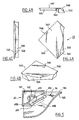
- FIG. 1A a view of the external face of the opening 10 of a “striking” type window conforming to a mode of realization of the invention.
- the opening 10 comprises a frame 100 formed of two vertical uprights 102 and 106 connected at their bevel ends by a lower cross member 104 and an upper cross member 108.
- the uprights and the crosspieces 102, 104, 106 and 108 are formed from an extruded wooden profile, plastic or metal.
- an external glazing 14 and a glazing internal 16 are mounted in abutment on the frame 100.
- the edges of the external glazing 14 are covered by elements of finishing or glazing beads 22, 26 and 24, 28 fixed respectively on the uprights 102, 106 and the crosspieces 104, 108 of the frame 100 by clipping into grooves formed along the profiles.
- These glazing beads 22, 24, 26 and 28 extend between four pieces angle 31, 33 (shown in dotted lines), 35, and 37 each positioned respectively in one of the angles 101, 103, 105, 107 of the frame 100 and making a junction between glazing beads 22, 24, 26 and 28.
- Piece angles 31, 33, 35, and 37 of generally triangular shape are also mounted by clipping in the extension of the clipping grooves intended for mounting glazing beads 22, 24, 26 and 28.
- the upper corner pieces 37 and 31 are so-called pieces "Breathable", they allow the passage of air between the defined space between the glazing 14 and 16 and the outside of the opening 10.
- the lower corner pieces 33 and 35 have a shape exterior similar to corner pieces 31 and 37. However, these pieces are so-called “non-breathable" parts, they do not allow exchange of air between the space 20 defined between the glazing 14 and 16 and the outside of opening it 10.
- the upper corners 141 and 147 of the external glazing 14 have been cut obliquely.
- the upper angle 141 positioned in the angle 101 of the frame 100 has been cut in direction X.
- the breathable corner piece 31 hides the missing angle of the glazing 14.
- Figure 1 E is a partial sectional view in the direction D-D of the upper breathable angle 101 of the opening 10 in which the corner piece 31.
- the profile of the upper cross member 108 of the frame 100 forms a rib 13 having two lateral surfaces 15 and 17 on which the internal glazing 16 and external glazing 14 respectively come in support.
- This rib 13 constitutes a spacer ensuring a spacing given between the two panes 14 and 16.
- the corner piece 31 includes a first element 41 or "corner” positioned in the extension of the glazing 14 at its angle coupe 141. It further comprises a second element 51 or “cover” superimposed on the corner 41 and masking from the outside the cut angle 141 of the external glazing 14.
- the cover 51 is held in the angle 101 of the frame 100 by clipping into the groove 19 formed in the profile of the cross member 108 and of the amount 102.
- the two elements 41 and 51 form an air passage (shown by an arrow) ensuring the communication of the space 20 formed between the two glazing 14 and 16 with the exterior.
- Figures 2A to 2D show in detail according to different views the corner 41 of the breathable corner piece 31 mounted on the angle 141 cut from the glazing 14 (shown in dotted lines).
- This corner 41 has the general shape of a right triangle. It includes a wall 402 bottom and edges 404, 406 and 408 extending perpendicular to the bottom wall 402 on its periphery. The two edges 404 and 406 forming a right angle are intended to be arranged respectively along the upright 102 and cross member 108 of frame 100 of opening 10 in the corner 101 of it. The third edge 408 of corner 41, opposite its right angle is intended to bear on the cutaway 141 of the external glazing 14 of so that this corner 41 extends the glazing 14.
- This third edge 408 has a lower lip 410 intended to come into contact with the inner surface 148 of the outer glazing 14 and two upper pins 412 and 414 positioned on either side of the lip lower 410 and intended to come into contact with the outer surface 146 of the external glazing 14.
- the lower lip 410 and the two upper pins 412 and 414 thus maintain the corner 41 in the extension of the angle cut 141 of the external glazing 14.
- the wall 402 at the bottom of the corner 41 has an opening 416 triangular giving it a general L shape.
- Each branch of the L-shaped wall is intended to come to bear on a rib 13 of profile of the upright 102 and upper cross member 108 of frame 100.
- This corner 41 allows in particular to support a filter (not shown) positioned on the wall 402 in L and covering the opening triangular 416.
- This filter allows air to pass through the opening triangular 416 while avoiding the introduction of particles or parasites between the two panes 14 and 16.
- FIGS. 3A to 3D show in detail according to different views, the cover 51 of the breathable corner piece 31.
- This cover 51 also has a general shape of a right triangle. It includes a plate 542 substantially flat intended to cover the corner 41 when the latter is positioned in the angle 101 of the frame 100.
- Each of the two edges 444 and 546 of the plate 542 forming a right angle is extended by a skirt 554, 556 extending perpendicularly to the plate 542.
- Each skirt 554 and 556 has along its free edge a protruding thickness 564, 566 towards the inside of the cover 51.
- These skirts 554 and 556 are intended to be introduced into the grooves 19 of the profiles forming the frame 100 for clip the cover 51 into the corner 101 of the frame 100.
- the cover 51 also has along its opposite edge 548 to its right angle an inclined lip 558 extending the flat surface of the plate 542 up to the external surface 146 of the external glazing 14.
- This lip 558 has an opening 568 allowing passage air between the plate 542 of the cover 51 and the corner filter 41 positioned under the cover 51 as represented by the arrow in FIG. 1 E.
- This “open” cover 51 protects and hides the corner 41 supporting the filtered.
- its inclined lip 558 causes the runoff of water from rain along its edge and thus prevents the introduction of water on the corner 41 and in the filter it contains.
- FIGS. 4A to 4D show in detail from different views, the cover 45 of the non-breathable corner piece 33 mounted in the lower corner 103 of the frame 100.
- This cover 45 has a general shape similar to the cover 51 of FIGS. 3A to 3D, except that it does not include an opening in its inclined lip 558.
- This lip 558 is full and is in contact with its entire free edge with the external surface 146 of the external glazing 14.
- This “plugged” cover 45 is mounted in the same way as the cover 51 by clipping into the lower corner 103 of the frame 100. At this point, the angle 143 of the external glazing 14 is not cut and the corner piece 33 does not has no breathable corner.
- these pieces of angles advantageously constitute safety parts ensuring the maintenance of the external glazing 14 on the frame 100 in the event, for example, of detachment of this glazing from frame 100 opening 10.
- breathing is not performed by cutting the angle of the glazing 14 but by piercing an opening 142 in the corner of this glazing.
- a corner 42 similar to the corner 41 of the Figure 2A but having a slot 409 formed between its lower lip 410 and its two upper pins 412 and 414 is positioned on the corner 141 pierced with glazing.
- the angle 141 of the glazing 14 is inserted into the slot 409 from corner 42 so that the triangular opening 416 of the L-shaped wall is superimposed on the pierced opening 142 of the glazing 14.
- the air circulates at through the triangular opening 416 and the pierced opening 142.
- the wedge 42 can advantageously support a filter.
- the window is pierced and we don't use a corner.
- the filter can be directly mounted on the pierced opening 142 of the glazing 14.
- An open cover similar to cover 51 of FIGS. 3A to 3D covers and protects the breathable corner of the glazing.
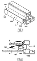
- the spacer 13 formed in the profiles of the cross member upper 108 and 102 of the opening 10 is machined in the corner 101 of the frame 100.
- This machining can for example consist of making in the thickness of the spacer 13 of a groove 144 by milling the spacer 13 at the junction between the upright 102 and the upper crossmember 108. Milling is made in the direction shown by the arrow F from the surface 17 of rib 13 in contact with the internal surface 148 of the external glazing 14.
- Figure 6E is a partial sectional view in the direction D-D of the upper breathable angle 101 of the opening 10. As illustrated in this figure, this machining consists in providing an air passage around the corner 141 external glazing 14. This passage allows air circulation (shown by an arrow) between the space 20 defined between the glazing 14 and 16 and outside.
- the angle 141 is also covered breathable from a protective cover similar to the cover 51 of FIGS. 3A to 3D. he it is also possible to cover this angle 141 with a corner piece less "covering" than in the implementations described above. It is advantageously possible to position a hood in this breathable angle. L-shape extending the glazing beads 22 and 28.
- the protective cover can also support a filter.
- FIG. 7 shows a profile 13 forming a spacer which has a T-shaped element 1300 consisting of a base 1302 and a head which is transverse to it 1304 forming two longitudinal ribs 1306,1308 located respectively on either side of the base 1302.
- One ribs 1306 serves to support the external glazing 14.
- the other rib 1308 serves as a support for the internal glazing 16.
Landscapes
- Engineering & Computer Science (AREA)
- Civil Engineering (AREA)
- Structural Engineering (AREA)
- Securing Of Glass Panes Or The Like (AREA)
- Specific Sealing Or Ventilating Devices For Doors And Windows (AREA)
Applications Claiming Priority (2)
| Application Number | Priority Date | Filing Date | Title |
|---|---|---|---|
| FR0206428 | 2002-05-27 | ||
| FR0206428A FR2840011B1 (fr) | 2002-05-27 | 2002-05-27 | Fenetre a double-vitrage respirant |
Publications (1)
| Publication Number | Publication Date |
|---|---|
| EP1367211A1 true EP1367211A1 (de) | 2003-12-03 |
Family
ID=29415100
Family Applications (1)
| Application Number | Title | Priority Date | Filing Date |
|---|---|---|---|
| EP03291261A Withdrawn EP1367211A1 (de) | 2002-05-27 | 2003-05-27 | Fenster mit belüfteter Doppelverglasung |
Country Status (3)
| Country | Link |
|---|---|
| EP (1) | EP1367211A1 (de) |
| CN (1) | CN1461866A (de) |
| FR (1) | FR2840011B1 (de) |
Cited By (3)
| Publication number | Priority date | Publication date | Assignee | Title |
|---|---|---|---|---|
| WO2005083218A1 (en) * | 2004-02-26 | 2005-09-09 | Mcguire Entreprises Inc. | Method of treating glazing panels |
| US8112860B2 (en) | 2003-12-17 | 2012-02-14 | Stephen Collins | Method of treating glazing panels |
| WO2019235941A1 (en) * | 2018-06-05 | 2019-12-12 | Hodges Michael Ross | Exterior vented glazing systems and methods of glazing |
Citations (4)
| Publication number | Priority date | Publication date | Assignee | Title |
|---|---|---|---|---|
| DE1064231B (de) * | 1955-12-10 | 1959-08-27 | Oskar Steinbach | Doppelt verglastes Fenster |
| DE2353666A1 (de) * | 1973-10-26 | 1975-05-07 | Wieland Werke Ag | Abgerundete eckstuecke fuer fenster und tueren |
| EP0292595A1 (de) * | 1987-05-27 | 1988-11-30 | CERA Handelsgesellschaft mbH | Mehrscheibenisolierglas |
| US5299399A (en) * | 1991-11-18 | 1994-04-05 | Pella Corporation | Window panel with breather system |
-
2002
- 2002-05-27 FR FR0206428A patent/FR2840011B1/fr not_active Expired - Fee Related
-
2003
- 2003-05-27 EP EP03291261A patent/EP1367211A1/de not_active Withdrawn
- 2003-05-27 CN CN 03136566 patent/CN1461866A/zh active Pending
Patent Citations (4)
| Publication number | Priority date | Publication date | Assignee | Title |
|---|---|---|---|---|
| DE1064231B (de) * | 1955-12-10 | 1959-08-27 | Oskar Steinbach | Doppelt verglastes Fenster |
| DE2353666A1 (de) * | 1973-10-26 | 1975-05-07 | Wieland Werke Ag | Abgerundete eckstuecke fuer fenster und tueren |
| EP0292595A1 (de) * | 1987-05-27 | 1988-11-30 | CERA Handelsgesellschaft mbH | Mehrscheibenisolierglas |
| US5299399A (en) * | 1991-11-18 | 1994-04-05 | Pella Corporation | Window panel with breather system |
Cited By (3)
| Publication number | Priority date | Publication date | Assignee | Title |
|---|---|---|---|---|
| US8112860B2 (en) | 2003-12-17 | 2012-02-14 | Stephen Collins | Method of treating glazing panels |
| WO2005083218A1 (en) * | 2004-02-26 | 2005-09-09 | Mcguire Entreprises Inc. | Method of treating glazing panels |
| WO2019235941A1 (en) * | 2018-06-05 | 2019-12-12 | Hodges Michael Ross | Exterior vented glazing systems and methods of glazing |
Also Published As
| Publication number | Publication date |
|---|---|
| CN1461866A (zh) | 2003-12-17 |
| FR2840011B1 (fr) | 2008-04-18 |
| FR2840011A1 (fr) | 2003-11-28 |
Similar Documents
| Publication | Publication Date | Title |
|---|---|---|
| EP0124397B1 (de) | Doppelverglasung und Herstellungsverfahren | |
| FR2508760A1 (fr) | Serre ventilee par une arete | |
| EP1400653B1 (de) | Schiebefenster oder -tür, dessen Flügel gegen einer an der Zarge angeordneten Abdichtung verriegelbar sind | |
| CH652167A5 (fr) | Aerateur. | |
| EP2186985B1 (de) | Gebäudeverschlusselement mit einer thermisch getrennten Zarge, die mit einem L-förmigen Dichtungsprofil ausgestattet ist | |
| EP1101894B1 (de) | Rahmen für Schiebetür oder -fenster | |
| EP1367211A1 (de) | Fenster mit belüfteter Doppelverglasung | |
| FR2948723A1 (fr) | Dispositif de drainage pour seuil de chassis de fermeture coulissant | |
| EP1700992B1 (de) | Fenster, Fenstertür oder dergleichen mit einem belüfteten Rahmen, mit Fluidverbindungsmitteln von einer Luftschicht zur Aussenumgebung über eine Profildichtung im unteren Querträger der Aussenglasscheibe | |
| FR2582702A1 (fr) | Plancher pour echafaudages muni d'une trappe d'acces amovible a deux battants | |
| EP3635210B1 (de) | Unterer querträger mit verbesserter wasserdichtigkeit für ein schiebefenster, schiebefenster mit einem solchen unteren querträger | |
| EP0497703B1 (de) | Mehrfachverglasung mit dynamischer Isolation | |
| EP0909866B1 (de) | Wandelement aus einem Profilrahmen und einer Isolierverglasung mit Stufenrand | |
| EP1403461B1 (de) | Atmungsfähiger Flügelrahmen | |
| EP0484235B1 (de) | Fenster- oder verglaste Türflugel mit wetterfester Bekleidung | |
| FR2557915A1 (fr) | Volet perfectionne destine a faire office de persienne a lames orientables | |
| FR2991706A1 (fr) | Cadre de menuiserie equipe d'un dispositif a vitrage respirant | |
| EP0953720A1 (de) | Belüftete Mehrfachverglasung | |
| CH636403A5 (en) | Profile for fitting items of insulating glazing and item of insulating glazing comprising such profiles | |
| EP1055794A1 (de) | Fenster mit einem seine unverdeckten Teile schützenden Abdeckung verbundenen Holzrahmen | |
| FR2851002A1 (fr) | Panneau vitre d'isolation acoustique et/ou thermique | |
| EP0180498A2 (de) | Fenster- oder Türrahmen mit zusätzlicher Beglasung und Vorrichtung für die Luftzirkulation zwischen den Glasscheiben | |
| FR2497867A1 (fr) | Fermeture en bois telle que porte vitree ou fenetre comportant des feuillures auto-drainantes | |
| FR3120892A1 (fr) | Dispositif d’aérateur de fenêtre et fenêtre équipée d’un tel dispositif d’aérateur. | |
| EP0823530A2 (de) | Aussenwand mit hoher Wärmeisolierung |
Legal Events
| Date | Code | Title | Description |
|---|---|---|---|
| PUAI | Public reference made under article 153(3) epc to a published international application that has entered the european phase |
Free format text: ORIGINAL CODE: 0009012 |
|
| AK | Designated contracting states |
Kind code of ref document: A1 Designated state(s): AT BE BG CH CY CZ DE DK EE ES FI FR GB GR HU IE IT LI LU MC NL PT RO SE SI SK TR |
|
| AX | Request for extension of the european patent |
Extension state: AL LT LV MK |
|
| 17P | Request for examination filed |
Effective date: 20040517 |
|
| AKX | Designation fees paid |
Designated state(s): AT BE BG CH CY CZ DE DK EE ES FI FR GB GR HU IE IT LI LU MC NL PT RO SE SI SK TR |
|
| 17Q | First examination report despatched |
Effective date: 20070813 |
|
| GRAP | Despatch of communication of intention to grant a patent |
Free format text: ORIGINAL CODE: EPIDOSNIGR1 |
|
| RIN1 | Information on inventor provided before grant (corrected) |
Inventor name: ALONZO, ANTONIO Inventor name: GROUSSARD, FRANCOIS |
|
| STAA | Information on the status of an ep patent application or granted ep patent |
Free format text: STATUS: THE APPLICATION IS DEEMED TO BE WITHDRAWN |
|
| 18D | Application deemed to be withdrawn |
Effective date: 20091106 |