EP1365597B1 - Bildprojektor mit Sensor zur Detektion von Hindernissen auf dem Projektionsschirm - Google Patents
Bildprojektor mit Sensor zur Detektion von Hindernissen auf dem Projektionsschirm Download PDFInfo
- Publication number
- EP1365597B1 EP1365597B1 EP03011063A EP03011063A EP1365597B1 EP 1365597 B1 EP1365597 B1 EP 1365597B1 EP 03011063 A EP03011063 A EP 03011063A EP 03011063 A EP03011063 A EP 03011063A EP 1365597 B1 EP1365597 B1 EP 1365597B1
- Authority
- EP
- European Patent Office
- Prior art keywords
- image
- projection
- area
- information
- sensing
- Prior art date
- Legal status (The legal status is an assumption and is not a legal conclusion. Google has not performed a legal analysis and makes no representation as to the accuracy of the status listed.)
- Expired - Fee Related
Links
Images

Classifications
-
- H—ELECTRICITY
- H04—ELECTRIC COMMUNICATION TECHNIQUE
- H04N—PICTORIAL COMMUNICATION, e.g. TELEVISION
- H04N9/00—Details of colour television systems
- H04N9/12—Picture reproducers
- H04N9/31—Projection devices for colour picture display, e.g. using electronic spatial light modulators [ESLM]
- H04N9/3179—Video signal processing therefor
- H04N9/3185—Geometric adjustment, e.g. keystone or convergence
-
- H—ELECTRICITY
- H04—ELECTRIC COMMUNICATION TECHNIQUE
- H04N—PICTORIAL COMMUNICATION, e.g. TELEVISION
- H04N17/00—Diagnosis, testing or measuring for television systems or their details
- H04N17/04—Diagnosis, testing or measuring for television systems or their details for receivers
-
- H—ELECTRICITY
- H04—ELECTRIC COMMUNICATION TECHNIQUE
- H04N—PICTORIAL COMMUNICATION, e.g. TELEVISION
- H04N5/00—Details of television systems
- H04N5/74—Projection arrangements for image reproduction, e.g. using eidophor
-
- H—ELECTRICITY
- H04—ELECTRIC COMMUNICATION TECHNIQUE
- H04N—PICTORIAL COMMUNICATION, e.g. TELEVISION
- H04N9/00—Details of colour television systems
- H04N9/12—Picture reproducers
- H04N9/31—Projection devices for colour picture display, e.g. using electronic spatial light modulators [ESLM]
- H04N9/3191—Testing thereof
- H04N9/3194—Testing thereof including sensor feedback
-
- H—ELECTRICITY
- H04—ELECTRIC COMMUNICATION TECHNIQUE
- H04N—PICTORIAL COMMUNICATION, e.g. TELEVISION
- H04N5/00—Details of television systems
- H04N5/74—Projection arrangements for image reproduction, e.g. using eidophor
- H04N5/7416—Projection arrangements for image reproduction, e.g. using eidophor involving the use of a spatial light modulator, e.g. a light valve, controlled by a video signal
- H04N5/7441—Projection arrangements for image reproduction, e.g. using eidophor involving the use of a spatial light modulator, e.g. a light valve, controlled by a video signal the modulator being an array of liquid crystal cells
- H04N2005/745—Control circuits therefor
-
- H—ELECTRICITY
- H04—ELECTRIC COMMUNICATION TECHNIQUE
- H04N—PICTORIAL COMMUNICATION, e.g. TELEVISION
- H04N5/00—Details of television systems
- H04N5/74—Projection arrangements for image reproduction, e.g. using eidophor
- H04N5/7416—Projection arrangements for image reproduction, e.g. using eidophor involving the use of a spatial light modulator, e.g. a light valve, controlled by a video signal
Definitions
- the present invention relates to a projector and image projection method which can change a projection position.
- Projectors such as liquid crystal projectors and the like have been used in classrooms, movie theaters, meeting rooms, exhibition grounds and domestic living rooms.
- a domestic living room is usually used not only by the user of a liquid crystal projector or the like, but also by the user's family. Even if the user has secured any larger area of wall surface as a projection area, anyone of his or her family may place a furniture or houseplant in front of that wall surface such that the furniture or houseplant will hide part of the projection area intended by the user.
- liquid crystal projector or the like is used to project a product introduction image or an advertisement image in an exhibition ground or the like, the image may be partially hidden behind any person who has unintentionally entered the projection area.
- the user may want to project the image onto the desired portion of the projection area depending on the situation in the projection.
- the user may usually project an image onto the wall of the living room and sometimes want to project another image illustrating a recipe onto the wall of the kitchen.
- a right-handed presenter may more easily point an image through a pointer when the image is displayed on the right side as viewed from audience while a left-handed presenter may more easily point the image through the pointer when the image is displayed on the left side as viewed from the audience.
- the user shifts the image projection position to perform a more effective presentation.
- the projector is manually adjusted in projection position and re-calibrated each time when one presenter is replaced by another.
- the partial illumination has been adopted even in home. If the projection position has been changed without change of the settings in the liquid crystal projector or the like, therefore, the image appearance intended by the user may highly be varied since the influence of the ambient light to the image is variable depending on the projection position.
- the present invention is made in view of the above-mentioned problems and its object is to provide a projector and image projection method which can easily change projection position.
- a user can more easily change the projection position since the projectable area including no obstacle (e.g., a desk, audience or the like) can automatically be determined.
- the projectable area including no obstacle e.g., a desk, audience or the like
- an image can be corrected depending on the viewing environment of the projection position by generating image correction data based on the result of sensing of the projection target area and using the image correction data to correct the input image information.
- an image view can be kept constant by correcting the image depending on the viewing environment of the projection position even if the projection position is changed.
- an image can be projected with its appropriate size since the association of the projection target area with the pixel area of the spatial light modulator can automatically carried out.
- the projector according to the present invention enables to perform automatic adjustment to project an image on the projection area having no obstacles by repeating the sensing and edge detection at a predetermined timing. So a user can more easily change the projection position.
- FIG. 1 is a schematic diagram showing a projection area according to one embodiment of the present invention.
- the wall When the wall is used as a projection target area 10 onto which an image is projected and if any obstacle such as a picture 20, a foliage plant 22 or the like, the wall may be hidden behind the obstacle. Thus, the liquid crystal projector may not adequately display an image.
- the picture 20 and/or foliage plant 22 may frequently be moved by any of the members. It is therefore difficult to secure the projection area adequately at all times.
- the image appearance is variable depending on the position of a fluorescent lamp 50.
- the partial illumination has taken in home.
- the image appearance is variable depending on the position onto which the liquid crystal projector projects an image in the living room.
- the liquid crystal projector senses the projection target area 10 through a CCD sensor for performing edge detection, determines a plurality of projection areas 40-1 to 40-3 which satisfy a predetermined aspect ratio and decides one of the projection areas 40 on selection of the user to project an image thereonto.
- the liquid crystal projector realizes an ideal image appearance by correcting the color and brightness of the image in consideration of the influence of an ambient light (an illuminating light from the fluorescent lamp 50 or sunlight) in a viewing environment (or an environment under which the image is actually viewed under the influence of the light from the fluorescent lamp 50 as well as the influence of the color in the projection area) and the influence of the projection plane (such as the color of the projection area, spectral reflection factor and the like).
- an ambient light an illuminating light from the fluorescent lamp 50 or sunlight
- a viewing environment or an environment under which the image is actually viewed under the influence of the light from the fluorescent lamp 50 as well as the influence of the color in the projection area
- the influence of the projection plane such as the color of the projection area, spectral reflection factor and the like.
- the user can reproduce an ideal image appearance even if the image projection position has been changed.
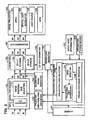
- FIG. 2 is a functional block diagram showing a liquid crystal projector according to one embodiment of the present invention.
- the projector comprises a sensor 60, an input signal processing section 110, a correction section 120, a D/A converter section 180, an image projection section 190, a projection-area-to pixel area association section 130, a projection area determination section 140, a calibration signal generation section 150, a sensing data generating section 170, an LUT data generation section 160 and an aspect-ratio determination section 132.
- the input signal processing section 110 converts R1-, G1- and B1-signals constituting analog R-, G- and B-signals which are a kind of input image information from PC (Personal Computer) or the like into digital R2-, G2- and B2-signals.
- PC Personal Computer
- the input signal processing section 110 comprises an A/D converter section 112 for performing such an analog to digital conversion and an image position/size adjustment section 114 which is part of an adjustment mean for adjusting the position and size of the image (which may adjust only the position or size of the image).
- A/D converter section 112 and D/A converter section 180 are unnecessary if only digital type R-, G- and B-signals are used in the projector.
- the calibration signal generation section 150 generates digital R2-, G2- and B2-signals used for projection of calibration images.
- the calibration can be made solely by the liquid crystal projector by internally generating calibration signals within the liquid crystal projector without inputting calibration signals from any external input device such as a PC or the like into liquid crystal projector.
- the calibration image signals may be inputted from PC or the like directly into the projector 20 without provision of the calibration signal generation section 150.
- the correction section 120 comprises a 3D-LUT (three-dimensional lookup table) storage section 122 and a 1D-LUT (one-dimensional lookup table) storage section 124.
- the correction section 120 corrects the color of an image using 3D-LUT and the brightness of the image using D-LUT.
- 3D-LUT and 1 D-LUT are kinds of image correction data.
- the image correction data may be in the form of a matrix, for example.
- the correction section 120 corrects the color, brightness and the like of the image to form output R3-, G3- and B3-signals, based on the R2-, G2- and B2-signals from the input signal processing section 110 or the calibration signal generation section 150.
- the D/A converter section 180 converts the R3-, G3- and B3-signals from the correction section 120 into analog R4-, G4- and B4-signals.
- the image projection section 190 comprises a drive section 191, a spatial light modulator 192 and a source of light 193 and a lens 195.
- the drive section 191 drives the spatial light modulator 192 based on the R4-, G4- and B4-signals from the D/A converter section 180.
- the image projection section 190 projects the light from the light source 193 through the spatial light modulator 192 and lens 195.
- the projection area decision region 140 included in the liquid crystal projector comprises a projection area selecting section 142, a projectable area determination section 144, an edge detection section 146 and a projection-range detection section 148.
- the projection-range detection section 148 detects the range of the projection target area 10 (which will also be referred to the projection range 10A), based on sensing information represented by X-, Y- and Z-values (tristimulus values of XYZ) from the sensor 60 which is a sensing means for sensing the projection target area 10.
- the X-, Y- and Z-values used herein are machinery independent colors which are based on the International Standard defined by the International Commission on Illumination (CIE).
- FIG. 1 shows the projection target area 10 which has the same size as the projection range 10A.
- the projection range 10A is intended to indicate the range in the projection target area 10 irradiated by a projection light.
- the edge detection section 146 performs the edge detection and outputs detection information, based on the X-, Y- and Z-values of the whole projection range 10A on the projection target area 10.
- the projectable area determination section 144 determines projection areas 40-1 to 40-3 which have no obstacle such as picture 10 or the like within the projection range 10A on the projection target area 10 and also which have a size equal to or larger than a fixed size satisfying the aspect ratio, based on the detection information and an aspect ratio determined by the aspect-ratio determination section 132 (for example, 16:9, 4:3 or the like). For simplicity, FIG. 1 shows three representative projection areas 40-1 to 40-3, but more projection areas 40 can actually be determined. Moreover, only one projection area may be determined.
- the projectable area determination section 144 detects a portion of the projection area surrounded by a boarder line on the outermost side thereof as a projectable area 30.
- a plurality of projectable areas 30 may be detected.
- the projection area selecting section 142 selects one of the projection areas 40-1 to 40-3 contained in the projectable area 30 according to user's instruction of selection (e.g., through a remote controller in the liquid crystal projector).
- the projection-area-to-pixel area association section 130 which is part of the adjusting means, associates the projection area in the projection range 10A on the projection target area 10 with the pixel area of the spatial light modulator 192, based on the projection range 10A on the projection target area 10 detected by the projection-range detection section 148 and the projection area selected by the projection area selecting section 142. More particularly, the projection-area-to-pixel area association section 130 determines a ratio between the projection range 10A on the projection target area 10 and the pixel area of the spatial light modulator 192.
- the projection-area-to-pixel area association section 130 may associates coordinates within the projection range 10A (or coordinates on a light-receiving element in the sensor 60) with coordinates on the projected image (or calibration image). This is because the coordinates on the projected image can be transformed into coordinates on the pixel area of the spatial light modulator 192 through a predetermined transformation.
- the image position/size adjustment section 114 adjusts the input image information to regulate the position and size of the image, based on the ratio determined by the projection-area-to-pixel area association section 130 and the positional information in the projection range 10A on the projection target area 10 in the projection area selected by the projection area selecting section 142.
- the liquid crystal projector comprises a sensing data generation section 170 for computing the mean value in the projection area from X-, Y- and Z-values for each pixel from the sensor 60 when a plurality of calibration images are projected, to correct the influence of the ambient light, and an LUT data generation section 160 for updating or generating 3D-LUT stored in the 3D-LUT storage section 122 and 1D-LUT stored in the 1D-LUT storage section 124, based on X-, Y- and Z-values for each calibration image.
- the sensing data generation section 170 computes the mean value of X-, Y- and Z-values of pixels in the projection area, based on the sensing information from the sensor 60 and information indicating the projection area from the projection area determination section 140.
- the LUT data generation section 160 which is an image correction data generating means, then generates 3D-LUT and 1D-LUT based on the computed mean value.
- the LUT data generation section 160 may generate the image correction data corresponding to a device using a device profile which has been held in the LUT data generation section 160.
- the image information can be corrected depending on the viewing environment in the projection area by generating the image correction data based on the mean value of the X-, Y- and Z-values which is sensing information for each of the pixels forming the projection area.
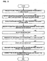
- FIG. 3 is a flow chart showing an image projecting procedure according to one embodiment of the present invention.
- the calibration signal generation section 150 produces calibration signals so that a plurality of single-colored calibration images (for example, white-, red-, green-, blue-, gray- and black-colored calibration images) will be displayed; the correction section 120 corrects color temperature and the like on the basis of normal liquid crystal projector settings; and the image projection section 190 sequentially projects the calibration images based on the corrected image information.
- a plurality of single-colored calibration images for example, white-, red-, green-, blue-, gray- and black-colored calibration images
- the sensor 60 measures X-, Y- and Z-values of each pixel (or a pixel in sensor 60 used to output the calibration image measurement through the sensor 60) in outputs measured value of the calibration image) in a calibration image displayed on the projection target area 10 (step S1).
- the projection-range detection section 148 detects the projection range 10, based on the difference for each pixel between X-, Y- and Z-values when the white-colored calibration image is displayed and X-, Y- and Z-values when the black-colored calibration image is displayed (step S2). In this case, it is preferably assumed, for example, that pixels having the difference equal to or more than 5 cd/m 2 are included in the projection range 10A on the projection target area 10. In place of the sensing information (X-, Y- and Z-values) when the black-colored calibration image is displayed, the sensing information in the projection range 10A on the projection target area 10 when the black-colored calibration image is not displayed may be used.
- the edge detection section 146 performs the edge detection, based on the X-, Y- and Z-values measured when the black-colored calibration image is displayed (step S3). More particularly, the edge detection section 146 is based on the X-, Y- and Z-values of the pixel in the projection range 10A detected by the projection-range detection section 148.
- the projectable area determination section 144 determines a projectable area 30 (i.e., an area including at least one projection area), based on the image aspect ratio from the aspect-ratio determination section 132 and the edge detection data from the edge detection section 146. More particularly, the projectable area determination section 144 detects the edge detection data in the projection range 10A from its left and upper location to its right and lower location to specify an area which satisfies a desired aspect ratio (i.e., one projection area). For example, if there is a polygon-shaped projectable area 30 as shown in FIG. 1, a plurality of projection areas 40-1 to 40-3 will be selected (step S4).
- the projection area determination section 140 outputs information indicative of these projection areas 40-1 to 40-3 selected by the projectable area determination section 144 toward the input signal processing section 110; and the image projection section 190 projects a selecting image for causing a user to select one of the projection areas 40-1 to 40-3.
- the input signal processing section 110 may have stored image information used to generate the selecting image.
- the projection area selecting section 142 selects one of the projection areas 40-1 to 40-3, based on a predetermined criterion (for example, it is at the upper end, lower end, left end or right end) or a user's instruction (step S5).
- the sensing data generation section 170 computes the mean value of X-, Y- and Z-values of each of the pixels forming the projection area in each calibration image, based on the sensing information from the sensor 60 and information indicating the projection area from the projection area determination section 140. Moreover, the LUT generating section 160 generates 3D-LUT and 1D-LUT based on the computed mean value (step S6) and updates the LUT data by storing them in the 3D-LUT and 1D-LUT storage sections 122, 124, respectively (step S7).
- the projection-area-to-pixel area association section 130 then associates the projection area with the pixel area of the spatial light modulator 192 (step S8).
- the image may be resized so that the entire range of the image represented by the image signals is projected onto the selected projection area.
- the image may be trimmed so that part of the image represented by the image signals is projected onto the selected projection area.
- the image position/size adjustment section 114 uses this association to adjust the digitally converted input image signals so that the position and size of the image will be adjusted and outputs digital signals (R2, G2, B2).
- the correction section 120 uses these digital signals (R2, G2, B2) to correct the image information so that the image takes the color and brightness corresponding to the viewing environment on the projection area; and the D/A converter section 180 performs the digital conversion against the image information (R3, G3, B3) from the correction section 120 and outputs analog signals (R4, G4, B4).
- the drive section 191 then drives the spatial light modulator 192 based on these analog signals (R4, G4, B4); and the image projection section 190 outputs a light from the light source 193 through the spatial light modulator 192 and lens 195 to project the image.
- the image projection section 190 can project the image corrected relating to its color and brightness onto the projection area (step S9).
- this embodiment can permit the user to change the projection position in a more simple and easy manner since the liquid crystal projector can automatically determine any suitable projectable area 30 on which there is no obstacle (for example, desk, audience or the like).
- a right-handed presenter may more easily point an image through a pointer when the image is displayed on the right side as viewed from audience while a left-handed presenter may more easily point the image through the pointer when the image is displayed on the left side as viewed from the audience.
- this embodiment permits the user to project the image onto any preferred position without need of any manual adjustment for the projector's projection position.
- the liquid crystal projector can project the image after the color and brightness thereof have been corrected for the viewing environment of the projection area selected from the projectable area by generating the sensing data from the computed mean values of the X-, Y- and Z-values of each of the pixels forming the projection area in each calibration image, based on the sensing information from the sensor 60 and the information indicative of the projection area from the projection area determination section 140 and by using the image correction data generated based on this sensing data.
- the liquid crystal projector can more simply and easily change the projection position, for example, even if the projection area 40 is continuously changed for display, since no calibration must be re-tried each time when the projection area is change.
- the liquid crystal projector can project the image with its appropriate size onto an appropriate position since the association of the projection range 10A on the projection target area 10 with the pixel area in the spatial light modulator 192 can automatically be carried out.
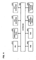
- FIG. 4 is a hardware block diagram showing a projection type image display system in a liquid crystal projector according to one embodiment of the present invention.
- these functions could be implemented by a computer within the liquid-crystal projector reading out a program from an information storage medium 300.
- the information storage medium 300 could be a CD-ROM, DVD-ROM, ROM, RAM, or HDD, by way of example, and the method of reading the program therefrom could be a direct method or an indirect method.
- the projectable area determination section 144 determines the projectable area 30 based on the edge detection information in a sensed image from the edge detecting section 146 in the above embodiment, but the projectable area 30 may be determined based on information other than the edge detection information.
- the projectable area determination section 144 may determine the projectable area 30 based on color distribution in a sensed image.
- the projectable area 30 can be selected by detecting distribution of X-, Y- and Z-values representing colors. The technique of selecting the projectable area 30 based on color distribution will be described below.
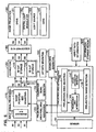
- FIG. 5 is a functional block diagram of a projection type image display system in a liquid crystal projector according to one embodiment of the present invention.
- the edge detecting section 146 is replaced by a color-distribution detection section 147 which outputs detection information indicating color distribution in a sensed image (which may be the whole or part of the sensed image) from the sensor 60, and the projectable area determination section 144 is replaced by a projectable area determination section 145.
- the color-distribution detection section 147 detects color distribution in the project region 10A based on the sensing information (X-, Y- and Z-values) relating to a portion corresponding to the project region 10A in the sensed image.
- the color-distribution detection section 147 generates a histogram (or frequency distribution) of X-, Y- and Z-values for a predetermined image processing unit (such as one pixel or a pixel block including a fixed number of pixels in horizontal and vertical directions).
- a predetermined image processing unit such as one pixel or a pixel block including a fixed number of pixels in horizontal and vertical directions.
- the color-distribution detection section 147 detects a range of X-value (XP1-XP2) having upper frequency in the histogram of X value. Similarly, the color-distribution detection section 147 detects a range of Y-value (YP1-YP2) having upper frequency and a range of Z-value (ZP1-ZP2) having upper frequency. These ranges are optional, so they may be identical with one another or different from one another.
- the color-distribution detection section 147 outputs the color-distribution information (XP1-XP2, YP1-YP2 and ZP1-ZP2) toward the projectable area determination section 145.
- the projectable area determination section 145 determines the projectable area 30, based on an aspect ratio of an image from the aspect ratio determination section 132 and the detection information of color distribution from the color-distribution detection section 147.
- the projectable area determination section 145 selects an area AX having an X-value corresponding to the range of X-value (XP1-XP2) from the color-distribution detection section 147, based on the sensing information relating to the projection area 10A in the sensed image.
- the sensing information has an ordinate position, an abscissa position, X-value, Y-value and Z-value for each coordinate position. Therefore, the projectable area determination section 145 can use the X-value as a search key to detect the ordinate and abscissa positions in the coordinates having the X-value, so that it can select the area AX.
- Areas AY and AZ for Y- and Z-values can be selected similarly.
- the projectable area determination section 145 selects the area AX having the X-value in the range of X-value (XP1-XP2), the area AY having the Y-value in the range of X-value (YP1-YP2) and the area AZ having the Z-value in the range of Z-value (ZP1-ZP2) in addition to an area AA in which the areas AX, AY and AZ overlap each other (e.g., the projectable area 30 in Fig. 1).
- the projectable area 30 can be selected.
- the remaining procedure portion may be accomplished by the steps after the above-mentioned step S3 in FIG. 3.
- the liquid crystal projector according to this embodiment can select an area satisfying the aspect ratio from among an area which has the same color and is not been influenced (or influenced) by the environment, as a projection area, even if part of the projection target area 10 has been influenced by that environment (due to the fluorescent lamp 50 or the like).
- the liquid crystal projector according to this embodiment can perform the processing more quickly (or more efficiently) since the edge detection can be omitted by adopting the technique based on the color distribution.
- the technique of detecting color distribution is not limited to the aforementioned technique.
- the range of X-, Y- or Z-value may be determined by calculating these values with different coefficient values or by using a certain function.
- the indexes for detecting color distribution may be in the form of R-, G- and B-values, other than the X-, Y- and Z-values.
- the liquid crystal projector may perform the following processing.
- the projection area can be determined by a process in which projecting and imaging of points or lines representing four corners of the rectangular image is repeatedly performed while narrowing the projection range, and the four corners in the sensed image is associated with the coordinates of the four corners in the spatial light modulator 192 at the point of detection of the points or lines representing the four corners by the sensor 60.
- the liquid crystal projector in the above embodiment uses a monochromatic black calibration image for the edge detection or other processing
- sensing information indicating differences between the X-, Y- and Z-values of a monochromatic white calibration image as a sensed image and the X-, Y- and Z-values of a monochromatic black calibration image as a sensed image may be used for the edge detection or other processing.
- the liquid crystal projector can perform the detection of color distribution and the like in a state the difference is reduced.
- the user's selection of the projection area may be carried out through a button or remote controller on the main body of the liquid crystal projector or through action or voice of the user.
- liquid crystal projector may perform the trapezoid skew correction or automatic focus adjustment when the image is projected.
- the projection area may have any configuration other than the rectangle-shaped configuration as in the aforementioned embodiment, such as a circular configuration.
- liquid crystal projector of this embodiment may repeatedly perform such an image projection as shown in FIG. 9 at a predetermined timing (e.g., with a predetermined time interval or at a time point when one presenter is replaced by another).
- a predetermined timing e.g., with a predetermined time interval or at a time point when one presenter is replaced by another.
- the liquid crystal projector can automatically perform such an adjustment that the image can be projected onto a projection area having no obstacle by repeating the sensing and edge detection operations at a predetermined timing when the position of an obstacle has been changed, more particularly, when the projection area is hidden by audience.
- the liquid crystal projector may further determine the projection area depending on the position of the obstacle.
- the liquid crystal projector of this embodiment may repeat such a process as shown by steps S1 to S9 in FIG. 3 if the image processing of FIG. 3 is repeated at the predetermined timing.
- the liquid crystal projector may repeat such a process as shown by steps S3 to S9 by performing only the sensing operation for the projection target area 10 on non-display (or the projected black-colored calibration image) at step 1 and omitting the procedure of step S2.
- the liquid crystal projector can not only perform such an adjustment that the image is projected onto a projecting area 40 having no obstacle, for example, when a new obstacle enters the projection area, but also project the image after it has been corrected for a new viewing environment when the older viewing environment has been changed.
- the liquid crystal projector can more simply and easily change the projection position without giving troublesome feelings to observers due to display of the colored calibration images, since the image can be projected onto the new projection area having no obstacle merely by performing the sensing operation for the projection target area 10 on non-display.
- one or more projection areas 40 satisfying the aspect ratio within the projectable area 30 may be selected after the projectable area 30 having no obstacle has been determined based on the edge detection data.
- image correction data (e.g., 3D-LUT, 1D-LUT and the like) may be generated based on the mean value of the X-, Y- and Z-values for each selectable projection area (for example, each of the projection areas 40-1 to 40-3 shown in FIG. 1). It may be then stored to correction section 120. The input image information may be then corrected while switching one changing image correction data to be applied to another, depending on selection of the projection area.
- the liquid crystal projector can apply the image correction data acceptable to the viewing environment within a reduced time period since it is not required to update the image correction data at each time when the projection area is changed, even though it is frequently changed.
- the projector according to this embodiment may be applied to any one of various projectors such as a projector using a digital micromirror device (DMD) and the like, other than the aforementioned liquid crystal projector.
- the aforementioned spatial light modulator may be in the form of an instrument consisting of a DMD tip and a color filter.
- DMD is a trademark possessed by the U. S. Texas Instruments.
- the projector is not limited to be of front projection type, but it may be of back projection type.
- the present invention can effectively be used even when an image is projected in the business such as a meeting room, a medical building-site, an advertisement spot, an education spot, a movie theater, an exhibition ground, rather than for the aforementioned domestic living rooms.
- the aforementioned function of the projector may be implemented by a single liquid crystal projector or by a plurality of distributed processing devices (e.g., a liquid crystal projector and personal computers).
Landscapes
- Engineering & Computer Science (AREA)
- Multimedia (AREA)
- Signal Processing (AREA)
- Biomedical Technology (AREA)
- Geometry (AREA)
- Health & Medical Sciences (AREA)
- Physics & Mathematics (AREA)
- General Health & Medical Sciences (AREA)
- Projection Apparatus (AREA)
- Controls And Circuits For Display Device (AREA)
- Transforming Electric Information Into Light Information (AREA)
- Control Of Indicators Other Than Cathode Ray Tubes (AREA)
- Liquid Crystal Display Device Control (AREA)
Claims (10)
- Projektor, aufweisend:eine Abtasteinrichtung (60), die ein Projektionszielgebiet (10) abtastet und Abtastinformation ausgibt;eine Erfassungseinrichtung (146), die eine Kantenerfassung oder eine Farbverteilungserfassung basierend auf der Abtastinformation durchführt und Erfassungsinformation ausgibt, welche eine Kante in einem abgetasteten Bild oder eine Farbverteilung in einem abgetasteten Bild angibt, um dadurch zu ermitteln, ob Hindernisse im Projektionszielgebiet (10) vorhanden sind;eine Projektionsgebiet-Bestimmungseinrichtung (144), die ein kein Hindernis aufweisendes projizierbares Gebiet (30) im Projektionszielgebiet (10) basierend auf der Erfassungsinformation bestimmt;eine Projektionsgebiet-Auswahleinrichtung (142), die ein Projektionsgebiet (40-1 - 40-3) aus dem projizierbaren Gebiet (30) auswählt, und zwar basierend auf einer Auswahl eines Benutzers oder einem vorbestimmten Kriterium;eine Anpassungseinrichtung (114), die ausgebildet ist, um Eingangsbildinformation basierend auf der Ausgabe der Auswahleinrichtung derart anzupassen, dass Position und/oder Größe des Bildes derart angepasst werden, dass das Bild auf dem ausgewählten Projektionsgebiet (40-1 - 40-3) angezeigt wird; undeine Bildprojektionseinrichtung (190), die ein Bild auf das ausgewählte Projektionsgebiet (40-1 -40-3) basierend auf der angepassten Eingangsbildinformation projiziert.
- Projektor nach Anspruch 1, weiter aufweisend:eine Bildkorrekturdaten-Erzeugungseinrichtung (160), die Bildkorrekturdaten erzeugt, die verwendet werden, um ein Bild in Abhängigkeit von der Betrachtungsumgebung zu korrigieren, und zwar basierend auf der Abtastinformation; undeine Korrektureinrichtung (120), welche die durch die Anpassungseinrichtung (114) angepasste Eingangsbildinformation korrigiert, und zwar basierend auf den Bildkorrekturdaten,wobei die Bildprojektionseinrichtung (190) ausgebildet ist, um ein Bild auf das Projektionsgebiet (40-1 - 40-3) basierend auf der durch die Korrektureinrichtung (120) korrigierten Eingangsbildinformation zu projizieren.
- Projektor nach Anspruch 2, bei dem die Bildkorrekturdaten-Erzeugungseinrichtung (160) ausgebildet ist, um die Betrachtungsumgebung des Projektionsgebietes (40-1 - 40-3) zu erfassen und die Bildkorrekturdaten zu erzeugen, und zwar basierend auf der Abtastinformation des Projektionsgebietes (40-1 - 40-3), das von der Projektionsgebiet-Auswahleinrichtung (142) ausgewählt wird.
- Projektor nach einem der Ansprüche 1 bis 3, bei dem:die Bildprojektionseinrichtung (190) einen räumlichen Lichtmodulator (192) aufweist; unddie Anpassungseinrichtung (114) ausgebildet ist, um eine Zuordnung des Projektionszielgebietes (10) basierend auf der Abtastinformation zu einem Pixelgebiet des räumlichen Lichtmodulators (192) durchzuführen, um die Eingangsbildinformation so anzupassen, dass die Position und/oder die Größe eines Bildes angepasst wird.
- Projektor nach Anspruch 4, bei dem:die Abtasteinrichtung (60) ausgebildet ist, um die Abtastinformation mit einer vorbestimmten Zeitsteuerung wiederholt durchzuführen und die Abtastinformation auszugeben;die Erfassungseinrichtung (146) ausgebildet ist, um die Erfassungsinformation basierend auf der neuesten Erfassungsinformation auszugeben; unddie Projektionsgebiet-Bestimmungseinrichtung (144) ausgebildet ist, um das projizierbare Gebiet (30) basierend auf der neuesten Erfassungsinformation zu bestimmen.
- Bildprojektionsverfahren, beinhaltend:Abtasten eines Projektionszielgebietes (10), um Abtastinformation auszugeben,Durchführen einer Kantenerfassung oder einer Farbverteilungserfassung basierend auf der Abtastinformation und Ausgeben von Erfassungsinformation, die eine Kante in einem abgetasteten Bild oder eine Farbverteilung in einem abgetasteten Bild angibt, um dadurch zu ermitteln, ob im Projektionszielgebiet (10) Hindernisse vorhanden sind;Bestimmen eines kein Hindernis aufweisenden projizierbaren Gebietes (30) im Projektionszielgebiet (10) basierend auf der Erfassungsinformation;Auswählen eines Projektionsgebietes (40-1 - 40-3) aus dem projizierbaren Gebiet (30), und zwar basierend auf einer Benutzerauswahl oder einem vorbestimmten Kriterium;Anpassen der Eingangsbildinformation basierend auf der Ausgabe der Auswahl, derart, dass eine Position und/oder eine Größe des Bildes derart angepasst werden, dass das Bild auf dem ausgewählten Projektionsgebiet (40-1 - 40-3) angezeigt wird; undProjizieren eines Bildes auf das ausgewählte Projektionsgebiet (40-1 - 40-3) basierend auf der angepassten Eingangsbildinformation.
- Verfahren nach Anspruch 6, weiter aufweisend:Erzeugen von Bildkorrekturdaten, die verwendet werden, um ein Bild in Abhängigkeit von der Betrachtungsumgebung zu korrigieren, und zwar basierend auf der Abtastinformation;Korrigieren der Eingangsbildinformation basierend auf den Bildkorrekturdaten; undProjizieren eines Bildes auf das Projektionsgebiet (40-1 - 40-3) basierend auf der durch die Korrektureinrichtung (120) korrigierten Eingangsbildinformation.
- Verfahren nach Anspruch 7, weiter aufweisend:Erfassen der Betrachtungsumgebung des Projektionsgebietes (40-1 - 40-3) und Erzeugen der Bildkorrekturdaten, und zwar basierend auf der Abtastinformation des ausgewählten Projektionsgebietes (40-1 - 40-3).
- Verfahren nach einem der Ansprüche 6 bis 8, weiter aufweisend:Zuordnen des Projektionszielgebietes (10) basierend auf der Abtastinformation zu einem Pixelgebiet eines räumlichen Lichtmodulators (192), um die Position und/oder die Größe eines Bildes anzupassen.
- Verfahren nach Anspruch 9, weiter aufweisend:wiederholtes Durchführen der Abtastoperation und Ausgeben der Erfassungsinformation mit einer vorbestimmten Zeitsteuerung; undBestimmen des projizierbaren Gebietes (30), basierend auf der neuesten Erfassungsinformation.
Applications Claiming Priority (4)
| Application Number | Priority Date | Filing Date | Title |
|---|---|---|---|
| JP2002144670 | 2002-05-20 | ||
| JP2002144670 | 2002-05-20 | ||
| JP2003127026A JP4009850B2 (ja) | 2002-05-20 | 2003-05-02 | 投写型画像表示システム、プロジェクタ、プログラム、情報記憶媒体および画像投写方法 |
| JP2003127026 | 2003-05-02 |
Publications (3)
| Publication Number | Publication Date |
|---|---|
| EP1365597A2 EP1365597A2 (de) | 2003-11-26 |
| EP1365597A3 EP1365597A3 (de) | 2004-01-28 |
| EP1365597B1 true EP1365597B1 (de) | 2007-02-21 |
Family
ID=29405341
Family Applications (1)
| Application Number | Title | Priority Date | Filing Date |
|---|---|---|---|
| EP03011063A Expired - Fee Related EP1365597B1 (de) | 2002-05-20 | 2003-05-20 | Bildprojektor mit Sensor zur Detektion von Hindernissen auf dem Projektionsschirm |
Country Status (5)
| Country | Link |
|---|---|
| US (2) | US7292252B2 (de) |
| EP (1) | EP1365597B1 (de) |
| JP (1) | JP4009850B2 (de) |
| CN (1) | CN1212562C (de) |
| DE (1) | DE60311915T2 (de) |
Families Citing this family (65)
| Publication number | Priority date | Publication date | Assignee | Title |
|---|---|---|---|---|
| JP4009850B2 (ja) * | 2002-05-20 | 2007-11-21 | セイコーエプソン株式会社 | 投写型画像表示システム、プロジェクタ、プログラム、情報記憶媒体および画像投写方法 |
| JP4009851B2 (ja) * | 2002-05-20 | 2007-11-21 | セイコーエプソン株式会社 | 投写型画像表示システム、プロジェクタ、プログラム、情報記憶媒体および画像投写方法 |
| DE60327289D1 (de) | 2002-07-23 | 2009-06-04 | Nec Display Solutions Ltd | Bildprojektor mit Bild-Rückkopplungs-Steuerung |
| US6916098B2 (en) * | 2003-05-14 | 2005-07-12 | Infocus Corporation | Preset key for a projection device |
| US7928994B2 (en) * | 2003-07-16 | 2011-04-19 | Transpacific Image, Llc | Graphics items that extend outside a background perimeter |
| US7274382B2 (en) * | 2003-07-16 | 2007-09-25 | Plut William J | Customizable background sizes and controls for changing background size |
| JP4055010B2 (ja) | 2003-09-26 | 2008-03-05 | セイコーエプソン株式会社 | 画像処理システム、プロジェクタ、プログラム、情報記憶媒体および画像処理方法 |
| JP2005099574A (ja) * | 2003-09-26 | 2005-04-14 | Nec Viewtechnology Ltd | 幾何学補正における光学中心補正のレンズシフト連動システム |
| JP2005192188A (ja) * | 2003-12-03 | 2005-07-14 | Seiko Epson Corp | プロジェクタ |
| JP4281593B2 (ja) * | 2004-03-24 | 2009-06-17 | セイコーエプソン株式会社 | プロジェクタの制御 |
| US7517089B2 (en) | 2004-03-29 | 2009-04-14 | Seiko Epson Corporation | Image processing system, projector, information storage medium, and image processing method |
| JP3882929B2 (ja) | 2004-03-29 | 2007-02-21 | セイコーエプソン株式会社 | 画像処理システム、プロジェクタおよび画像処理方法 |
| JP3722146B1 (ja) * | 2004-06-16 | 2005-11-30 | セイコーエプソン株式会社 | プロジェクタおよび画像補正方法 |
| JP4126564B2 (ja) | 2005-02-14 | 2008-07-30 | セイコーエプソン株式会社 | 画像処理システム、プロジェクタ、プログラム、情報記憶媒体および画像処理方法 |
| JP4085283B2 (ja) * | 2005-02-14 | 2008-05-14 | セイコーエプソン株式会社 | 画像処理システム、プロジェクタ、プログラム、情報記憶媒体および画像処理方法 |
| US20060274209A1 (en) * | 2005-06-03 | 2006-12-07 | Coretronic Corporation | Method and a control device using the same for controlling a display device |
| JP2007078821A (ja) * | 2005-09-12 | 2007-03-29 | Casio Comput Co Ltd | 投影装置、投影方法及びプログラム |
| KR100763235B1 (ko) * | 2005-10-21 | 2007-10-04 | 삼성전자주식회사 | 모니터의 색특성을 보정하는 방법 및 장치 |
| US8246172B2 (en) | 2006-02-28 | 2012-08-21 | Brother Kogyo Kabushiki Kaisha | Image display device |
| JP5014154B2 (ja) * | 2006-08-29 | 2012-08-29 | パナソニック株式会社 | 画像表示方法及び画像表示装置 |
| US8052598B2 (en) * | 2006-10-12 | 2011-11-08 | General Electric Company | Systems and methods for calibrating an endoscope |
| US9582805B2 (en) | 2007-10-24 | 2017-02-28 | Invention Science Fund I, Llc | Returning a personalized advertisement |
| US20090112693A1 (en) * | 2007-10-24 | 2009-04-30 | Jung Edward K Y | Providing personalized advertising |
| JP4341723B2 (ja) * | 2008-02-22 | 2009-10-07 | パナソニック電工株式会社 | 光投影装置、照明装置 |
| US20100253700A1 (en) * | 2009-04-02 | 2010-10-07 | Philippe Bergeron | Real-Time 3-D Interactions Between Real And Virtual Environments |
| KR101354400B1 (ko) | 2009-09-01 | 2014-01-22 | 엔터테인먼트 익스페리언스 엘엘씨 | 컬러 이미지를 생성하기 위한 방법 및 이를 이용하는 이미징 장치 |
| US8860751B2 (en) | 2009-09-01 | 2014-10-14 | Entertainment Experience Llc | Method for producing a color image and imaging device employing same |
| JP5560721B2 (ja) * | 2010-01-12 | 2014-07-30 | セイコーエプソン株式会社 | 画像処理装置、画像表示システム、及び画像処理方法 |
| JP2011255593A (ja) * | 2010-06-09 | 2011-12-22 | Canon Inc | 記録装置 |
| US8665286B2 (en) * | 2010-08-12 | 2014-03-04 | Telefonaktiebolaget Lm Ericsson (Publ) | Composition of digital images for perceptibility thereof |
| JP2012047842A (ja) * | 2010-08-25 | 2012-03-08 | Seiko Epson Corp | 画像表示装置および画像表示方法 |
| JP5541031B2 (ja) * | 2010-09-16 | 2014-07-09 | セイコーエプソン株式会社 | プロジェクター、およびプロジェクターの制御方法 |
| EP2680931A4 (de) * | 2011-03-04 | 2015-12-02 | Eski Inc | Vorrichtungen und verfahren zur bereitstellung einer verteilten kundgebung in einer umgebung |
| JP2012234060A (ja) * | 2011-05-02 | 2012-11-29 | Ricoh Co Ltd | 映像表示装置 |
| JP6102079B2 (ja) * | 2012-04-05 | 2017-03-29 | カシオ計算機株式会社 | 投影装置、投影方法及びプログラム |
| US9456187B1 (en) | 2012-06-01 | 2016-09-27 | Amazon Technologies, Inc. | Edge-based pose detection |
| US10528853B1 (en) * | 2012-06-29 | 2020-01-07 | Amazon Technologies, Inc. | Shape-Based Edge Detection |
| US9817305B2 (en) | 2012-07-12 | 2017-11-14 | Cj Cgv Co., Ltd. | Image correction system and method for multi-projection |
| MX348043B (es) * | 2012-08-01 | 2017-05-24 | Pentair Water Pool & Spa Inc | Proyección subacuática con calibración de bordes y corrección de imagen. |
| US9134599B2 (en) * | 2012-08-01 | 2015-09-15 | Pentair Water Pool And Spa, Inc. | Underwater image projection controller with boundary setting and image correction modules and interface and method of using same |
| US9423608B2 (en) | 2012-08-01 | 2016-08-23 | Pentair Water Pool And Spa, Inc. | Multidimensional rotary motion apparatus moving a reflective surface and method of operating same |
| US9325956B2 (en) | 2013-04-30 | 2016-04-26 | Disney Enterprises, Inc. | Non-linear photometric projector compensation |
| CN104378566B (zh) * | 2013-08-12 | 2017-12-26 | 联想(北京)有限公司 | 一种投影方法以及一种电子设备 |
| US20150181151A1 (en) * | 2013-12-19 | 2015-06-25 | Echostar Technologies L.L.C. | Systems and methods for multiple users changing channels on multiple displays |
| US9319649B2 (en) * | 2014-02-13 | 2016-04-19 | Disney Enterprises, Inc. | Projector drift corrected compensated projection |
| CN103974026B (zh) * | 2014-04-17 | 2017-10-17 | 华为技术有限公司 | 视讯信息呈现方法、装置及系统 |
| US10122976B2 (en) * | 2014-12-25 | 2018-11-06 | Panasonic Intellectual Property Management Co., Ltd. | Projection device for controlling a position of an image projected on a projection surface |
| US9565409B2 (en) * | 2015-06-25 | 2017-02-07 | Intel Corporation | Technologies for projecting a noncontinuous image |
| JP2017068058A (ja) * | 2015-09-30 | 2017-04-06 | ソニー株式会社 | 画像処理装置、画像処理方法、およびプログラム |
| US10445046B2 (en) | 2016-04-04 | 2019-10-15 | Abl Ip Holding, Llc | System and method for displaying dynamic information from a remote information source at locations within a premises |
| JP2019536494A (ja) | 2016-09-07 | 2019-12-19 | エスキー インコーポレイテッドESKI Inc. | 分散発現の投影システム及び関連する方法 |
| KR101820905B1 (ko) * | 2016-12-16 | 2018-01-22 | 씨제이씨지브이 주식회사 | 촬영장치에 의해 촬영된 이미지 기반의 투사영역 자동보정 방법 및 이를 위한 시스템 |
| CN107027014A (zh) * | 2017-03-23 | 2017-08-08 | 广景视睿科技(深圳)有限公司 | 一种动向智能投影系统及其方法 |
| JP2019032495A (ja) * | 2017-08-10 | 2019-02-28 | キヤノン株式会社 | 画像投射装置 |
| CN107422590B (zh) * | 2017-09-12 | 2020-09-08 | 中广热点云科技有限公司 | 自动调节投影面大小的家用投影系统 |
| CN109996051B (zh) * | 2017-12-31 | 2021-01-05 | 广景视睿科技(深圳)有限公司 | 一种投影区域自适应的动向投影方法、装置及系统 |
| CN108391105A (zh) * | 2018-03-05 | 2018-08-10 | 联想(北京)有限公司 | 一种控制投影的方法及电子设备 |
| JP2021121878A (ja) * | 2018-05-16 | 2021-08-26 | ソニーグループ株式会社 | 情報処理装置、情報処理方法、および記録媒体 |
| CN108600716A (zh) * | 2018-05-17 | 2018-09-28 | 京东方科技集团股份有限公司 | 投影设备和系统、投影方法 |
| JP2020034765A (ja) | 2018-08-30 | 2020-03-05 | ソニー株式会社 | 情報処理装置、情報処理方法及びプログラム |
| US11196985B1 (en) | 2018-12-28 | 2021-12-07 | Facebook, Inc. | Surface adaptation for projection-based augmented reality system |
| US11172189B1 (en) * | 2018-12-28 | 2021-11-09 | Facebook, Inc. | User detection for projection-based augmented reality system |
| JP7336027B2 (ja) | 2020-04-24 | 2023-08-30 | 富士フイルム株式会社 | 制御方法、投影装置、及び制御プログラム |
| CN113473095B (zh) * | 2021-05-27 | 2022-10-21 | 广景视睿科技(深圳)有限公司 | 一种避障动向投影的方法和设备 |
| CN116006061A (zh) * | 2021-10-21 | 2023-04-25 | 成都极米科技股份有限公司 | 投影控制方法、装置、电子设备以及计算机可读存储介质 |
Family Cites Families (20)
| Publication number | Priority date | Publication date | Assignee | Title |
|---|---|---|---|---|
| US5040116A (en) * | 1988-09-06 | 1991-08-13 | Transitions Research Corporation | Visual navigation and obstacle avoidance structured light system |
| US4950069A (en) * | 1988-11-04 | 1990-08-21 | University Of Virginia | Eye movement detector with improved calibration and speed |
| FR2660090B1 (fr) * | 1990-03-23 | 1994-07-29 | Thomson Csf | Dispositif de visualisation par projection a boucle de contre-reaction pour la correction de l'ensemble des defauts de l'image projetee. |
| US5375177A (en) * | 1991-09-27 | 1994-12-20 | E. I. Du Pont De Nemours And Company | Method of identifying and characterizing a valid object by color |
| US5436639A (en) * | 1993-03-16 | 1995-07-25 | Hitachi, Ltd. | Information processing system |
| JPH07162743A (ja) * | 1993-12-03 | 1995-06-23 | Matsushita Electric Ind Co Ltd | 映写装置用画像処理装置および映写装置 |
| US5563988A (en) * | 1994-08-01 | 1996-10-08 | Massachusetts Institute Of Technology | Method and system for facilitating wireless, full-body, real-time user interaction with a digitally represented visual environment |
| US6005534A (en) * | 1996-04-26 | 1999-12-21 | Dahlgren, Hylin & Jonason Media Ab | Digital information system |
| JP3679512B2 (ja) * | 1996-07-05 | 2005-08-03 | キヤノン株式会社 | 画像抽出装置および方法 |
| US6394557B2 (en) * | 1998-05-15 | 2002-05-28 | Intel Corporation | Method and apparatus for tracking an object using a continuously adapting mean shift |
| US6422704B1 (en) | 1998-06-26 | 2002-07-23 | Matsushita Electric Industrial Co., Ltd. | Projector that automatically adjusts the projection parameters |
| JP3630015B2 (ja) * | 1999-04-21 | 2005-03-16 | セイコーエプソン株式会社 | 投写型表示装置及び情報記憶媒体 |
| EP1065560A1 (de) | 1999-07-02 | 2001-01-03 | Optronik GmbH Potsdam | Verfahren und Anordnung zur Projektion von Bildern unter spitzen Winkeln |
| JP4192400B2 (ja) | 1999-12-28 | 2008-12-10 | ソニー株式会社 | 画像投射方法及び画像投射装置 |
| US20030025649A1 (en) * | 2000-09-08 | 2003-02-06 | Wynne Willson Peter David | Image projection apparatus |
| KR100396683B1 (ko) | 2001-01-08 | 2003-09-03 | 엘지전자 주식회사 | 티브이의 화면밝기/색도 보정장치 및 방법 |
| JP4776083B2 (ja) * | 2001-02-05 | 2011-09-21 | シャープ株式会社 | 表示装置、及びコンピュータに実行させる表示方法 |
| JP2002311503A (ja) | 2001-04-19 | 2002-10-23 | Mitsubishi Electric Corp | 画質補正システム |
| JP2003283964A (ja) * | 2002-03-26 | 2003-10-03 | Olympus Optical Co Ltd | 映像表示装置 |
| JP4009850B2 (ja) * | 2002-05-20 | 2007-11-21 | セイコーエプソン株式会社 | 投写型画像表示システム、プロジェクタ、プログラム、情報記憶媒体および画像投写方法 |
-
2003
- 2003-05-02 JP JP2003127026A patent/JP4009850B2/ja not_active Expired - Fee Related
- 2003-05-16 US US10/438,897 patent/US7292252B2/en not_active Expired - Lifetime
- 2003-05-16 CN CN03136209.5A patent/CN1212562C/zh not_active Expired - Lifetime
- 2003-05-20 EP EP03011063A patent/EP1365597B1/de not_active Expired - Fee Related
- 2003-05-20 DE DE60311915T patent/DE60311915T2/de not_active Expired - Lifetime
-
2007
- 2007-09-18 US US11/898,987 patent/US20080024514A1/en not_active Abandoned
Also Published As
| Publication number | Publication date |
|---|---|
| US20040036813A1 (en) | 2004-02-26 |
| EP1365597A3 (de) | 2004-01-28 |
| JP2004048694A (ja) | 2004-02-12 |
| CN1212562C (zh) | 2005-07-27 |
| US20080024514A1 (en) | 2008-01-31 |
| EP1365597A2 (de) | 2003-11-26 |
| CN1460919A (zh) | 2003-12-10 |
| US7292252B2 (en) | 2007-11-06 |
| DE60311915T2 (de) | 2007-10-25 |
| DE60311915D1 (de) | 2007-04-05 |
| JP4009850B2 (ja) | 2007-11-21 |
Similar Documents
| Publication | Publication Date | Title |
|---|---|---|
| EP1365597B1 (de) | Bildprojektor mit Sensor zur Detektion von Hindernissen auf dem Projektionsschirm | |
| EP1855471B1 (de) | Projektor, Informationsspeicherungsmedium und Bildprojektionssverfahren | |
| EP1265219B1 (de) | Sich an die umgebung anpassendes anzeigesystem, bildverarbeitungsverfahren und bildspeichermedium | |
| EP1205902B1 (de) | Bildanzeigesystem, Bildverarbeitungsverfahren und Informationsspeichermedium | |
| EP1349387B1 (de) | Bildanzeigesystem, Bildverarbeitungsverfahren und Informationsspeichermedium | |
| EP1473933B1 (de) | Bildverarbeitungssystem, Projektor, Speichermedium und Bildverarbeitungsverfahren | |
| EP2302919B1 (de) | Projektor | |
| JP4591720B2 (ja) | 投写型画像表示システム、プロジェクタ、プログラム、情報記憶媒体および画像投写方法 | |
| JP2013020093A (ja) | 画像投射装置、色補正方法およびプログラム | |
| JP4591719B2 (ja) | 投写型画像表示システム、プロジェクタ、プログラム、情報記憶媒体および画像投写方法 | |
| JP2008206067A (ja) | 画像データ処理方法、および、画像表示方法 | |
| KR100629529B1 (ko) | 프로젝터의 화면 밝기 자동 조정장치 및 방법 | |
| JP4164659B2 (ja) | 画像表示システムおよび画像表示方法 |
Legal Events
| Date | Code | Title | Description |
|---|---|---|---|
| PUAI | Public reference made under article 153(3) epc to a published international application that has entered the european phase |
Free format text: ORIGINAL CODE: 0009012 |
|
| AK | Designated contracting states |
Kind code of ref document: A2 Designated state(s): AT BE BG CH CY CZ DE DK EE ES FI FR GB GR HU IE IT LI LU MC NL PT RO SE SI SK TR |
|
| AX | Request for extension of the european patent |
Extension state: AL LT LV MK |
|
| PUAL | Search report despatched |
Free format text: ORIGINAL CODE: 0009013 |
|
| AK | Designated contracting states |
Kind code of ref document: A3 Designated state(s): AT BE BG CH CY CZ DE DK EE ES FI FR GB GR HU IE IT LI LU MC NL PT RO SE SI SK TR |
|
| AX | Request for extension of the european patent |
Extension state: AL LT LV MK |
|
| 17P | Request for examination filed |
Effective date: 20040212 |
|
| AKX | Designation fees paid |
Designated state(s): DE FR GB |
|
| 17Q | First examination report despatched |
Effective date: 20041008 |
|
| GRAP | Despatch of communication of intention to grant a patent |
Free format text: ORIGINAL CODE: EPIDOSNIGR1 |
|
| GRAS | Grant fee paid |
Free format text: ORIGINAL CODE: EPIDOSNIGR3 |
|
| GRAA | (expected) grant |
Free format text: ORIGINAL CODE: 0009210 |
|
| AK | Designated contracting states |
Kind code of ref document: B1 Designated state(s): DE FR GB |
|
| REG | Reference to a national code |
Ref country code: GB Ref legal event code: FG4D |
|
| RIN1 | Information on inventor provided before grant (corrected) |
Inventor name: MATSUDA, HIDEKI,SEIKO EPSON COR. |
|
| REF | Corresponds to: |
Ref document number: 60311915 Country of ref document: DE Date of ref document: 20070405 Kind code of ref document: P |
|
| ET | Fr: translation filed | ||
| PLBE | No opposition filed within time limit |
Free format text: ORIGINAL CODE: 0009261 |
|
| STAA | Information on the status of an ep patent application or granted ep patent |
Free format text: STATUS: NO OPPOSITION FILED WITHIN TIME LIMIT |
|
| 26N | No opposition filed |
Effective date: 20071122 |
|
| REG | Reference to a national code |
Ref country code: FR Ref legal event code: PLFP Year of fee payment: 14 |
|
| REG | Reference to a national code |
Ref country code: FR Ref legal event code: PLFP Year of fee payment: 15 |
|
| REG | Reference to a national code |
Ref country code: FR Ref legal event code: PLFP Year of fee payment: 16 |
|
| PGFP | Annual fee paid to national office [announced via postgrant information from national office to epo] |
Ref country code: DE Payment date: 20190508 Year of fee payment: 17 |
|
| PGFP | Annual fee paid to national office [announced via postgrant information from national office to epo] |
Ref country code: FR Payment date: 20190410 Year of fee payment: 17 |
|
| PGFP | Annual fee paid to national office [announced via postgrant information from national office to epo] |
Ref country code: GB Payment date: 20190515 Year of fee payment: 17 |
|
| REG | Reference to a national code |
Ref country code: DE Ref legal event code: R119 Ref document number: 60311915 Country of ref document: DE |
|
| GBPC | Gb: european patent ceased through non-payment of renewal fee |
Effective date: 20200520 |
|
| PG25 | Lapsed in a contracting state [announced via postgrant information from national office to epo] |
Ref country code: FR Free format text: LAPSE BECAUSE OF NON-PAYMENT OF DUE FEES Effective date: 20200531 Ref country code: GB Free format text: LAPSE BECAUSE OF NON-PAYMENT OF DUE FEES Effective date: 20200520 |
|
| PG25 | Lapsed in a contracting state [announced via postgrant information from national office to epo] |
Ref country code: DE Free format text: LAPSE BECAUSE OF NON-PAYMENT OF DUE FEES Effective date: 20201201 |