EP1365482A2 - Structure de verrouillage - Google Patents
Structure de verrouillage Download PDFInfo
- Publication number
- EP1365482A2 EP1365482A2 EP02025660A EP02025660A EP1365482A2 EP 1365482 A2 EP1365482 A2 EP 1365482A2 EP 02025660 A EP02025660 A EP 02025660A EP 02025660 A EP02025660 A EP 02025660A EP 1365482 A2 EP1365482 A2 EP 1365482A2
- Authority
- EP
- European Patent Office
- Prior art keywords
- arm
- lock
- cancellation
- leg
- retaining portion
- Prior art date
- Legal status (The legal status is an assumption and is not a legal conclusion. Google has not performed a legal analysis and makes no representation as to the accuracy of the status listed.)
- Withdrawn
Links
- 230000013011 mating Effects 0.000 claims abstract description 4
- 238000010276 construction Methods 0.000 description 5
- 230000000694 effects Effects 0.000 description 2
- 229920003002 synthetic resin Polymers 0.000 description 2
- 239000000057 synthetic resin Substances 0.000 description 2
- 230000008094 contradictory effect Effects 0.000 description 1
- 230000000881 depressing effect Effects 0.000 description 1
- 230000000994 depressogenic effect Effects 0.000 description 1
- 238000006073 displacement reaction Methods 0.000 description 1
- 230000002708 enhancing effect Effects 0.000 description 1
- 230000037431 insertion Effects 0.000 description 1
- 238000003780 insertion Methods 0.000 description 1
- 230000008719 thickening Effects 0.000 description 1
Images


Classifications
-
- H—ELECTRICITY
- H01—ELECTRIC ELEMENTS
- H01R—ELECTRICALLY-CONDUCTIVE CONNECTIONS; STRUCTURAL ASSOCIATIONS OF A PLURALITY OF MUTUALLY-INSULATED ELECTRICAL CONNECTING ELEMENTS; COUPLING DEVICES; CURRENT COLLECTORS
- H01R13/00—Details of coupling devices of the kinds covered by groups H01R12/70 or H01R24/00 - H01R33/00
- H01R13/62—Means for facilitating engagement or disengagement of coupling parts or for holding them in engagement
- H01R13/627—Snap or like fastening
- H01R13/6271—Latching means integral with the housing
- H01R13/6272—Latching means integral with the housing comprising a single latching arm
Definitions
- This invention relates to a lock structure for connecting tow parts or members, such as connectors, together, and more particularly to a lock structure having a mechanism for canceling a locked condition.
- Figs. 9 and 10 show one known structure in which male and female connector housings or the like are connected together, and this connected condition is locked, and this locked condition is canceled.
- a lock arm 37 is pivotally supported resiliently on the female connector housing 33 through a leg portion 35 at a generally central portion of the lock arm 37.
- a retaining portion 39 is formed at one end of the lock arm 37 while a cancellation portion 45 is provided at the other end thereof.
- a load is applied to the cancellation portion 45 by the finger to lift the retaining portion 39 of the lock arm 37, thereby canceling the engagement between the retaining portion 39 and a retaining portion 43 of the male connector housing 41.
- Such a lock structure is proposed in Japanese Utility Model unexamined publication Nos. 61-60482 and 3-39272.
- a lock structure shown in Figs. 11 and 12, is proposed in Japanese Utility Model Unexamined Publication No. 2-54180.
- lock arms 51 are pivotally supported resiliently on a male connector housing 47 at their respective leg portions 49, and cancellation arms 53 are also provided on the male connector housing 47.
- a retaining portion 55 is formed at distal ends of the lock arms 51.
- the cancellation arms 53 are connected to the distal end of the lock arms 51, and extend beyond the leg portions 49 in a direction away from the retaining portion 55, and a cancellation portion 57 is formed at rear ends of the cancellation arms 53.
- Stopper portions 59 for preventing excessive depressing of the cancellation arms 53 are formed on the male connector housing 47.
- a load is applied to the cancellation portion 57 by the finger to lift the retaining portion 55 of the lock arms 51, thereby canceling the engagement between the retaining portion 55 and a retaining portion 63 of a female connector housing 61.
- the cancellation arms are supported on the distal end portion (the retaining portion) of the lock arms, and therefore even when a force is applied to the cancellation arms, the retaining portion of the lock arms, in some cases, are not displaced in the cancelling direction before the cancellation arms are brought into abutting engagement with the stopper portions, and therefore the cancelling ability is low.
- the displacement of the distal end portion (the retaining portion) is not constant, but varies depending on the direction and angle of the force applied to the cancellation arms for lock-cancelling purposes, and therefore the retaining portion is not displaced in the cancelling direction, which results in a possibility that the locked condition can not be positively cancelled.
- the lock arm and the cancellation arm have their respective independent leg portions, and therefore for cancelling a locked condition, the retaining portion is positively displaced about the leg portion in a cancelling direction in accordance with a force applied to the cancellation arm to pivotally move the same. Therefore, the cancelling ability is enhanced.
- the required locking strength can be obtained by thickening the leg portion of the lock arm.
- the thickness of the leg portion of the cancellation arm can be set to a desired value in view of the cancelling ability and so on.
- the leg portion of the cancellation arm and the leg portion of the lock arm can be disposed respectively at different positions spaced from each other in the direction of extending of the arm. With this arrangement, the locking strength and the lock-cancelling ability can be adjusted independently of each other. Namely, the enhancement of the locking strength and the enhancement of the canceling ability are compatible with each other.
- the leg portion of the cancellation arm is thinned, the resistance of the cancellation arm (due to its elastic force and so on) to the pivotal movement of the lock arm is reduced, so that the force, required for canceling the locked condition, is reduced, and therefore this is desirable.
- leg portion of the cancellation arm is disposed closer to the retaining portion than the leg portion of the lock arm is, the force, required for canceling the locked condition, is reduced because of the effect of leverage, thereby enhancing the canceling ability, and therefore this is desirable.
- the lock arm, the cancellation arm, and their leg portions can be molded integrally with a connector housing, using a synthetic resin or the like, and by doing so, the lock structure of the present invention can be provided easily.
- Figs. 1(a) and 1(b) are perspective views of the lock structure.
- Fig. 2 is a plan view of a female connector housing
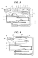
- Figs. 3 and 4 are cross-sectional views of the female connector housing
- Fig. 5 is a front-elevational view of a lock portion
- Fig. 6 is a plan view thereof
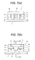
- Figs. 7(a) and 7(b) are side-elevational views thereof
- Fig. 8 is a cross-sectional view thereof.
- the lock portion 1 having features of the present invention, is formed integrally with the female connector housing 3 made of a synthetic resin, and more specifically this lock portion 1 is formed on an upper wall 7 of the female connector housing 3 having terminal receiving chambers 5.
- a lock arm 9 includes two curved leg portions 11, formed on and extending from the upper wall 7, and two arm portions 13 extending respectively from the two leg portions 11.
- the arm portions 13 extend parallel to the upper wall 7 in a direction of insertion of the female connector housing 3.
- a retaining portion 17, having a retaining pawl 15, is formed at distal ends of the two arm portions 13, and interconnects the two arm portions 13.
- a cancellation arm 19 includes two leg portions 21, extending from the upper wall 7, and two arm portions 23 formed respectively on the two leg portions 21, the leg portions 21 being smaller in thickness than the leg portions 11.
- the two leg portions 21 are disposed adjacent to outer side surfaces of the two leg portions 11 of the lock arm 9, respectively, and are disposed generally at the same positions as those of the leg portions 11.
- One end portion of each arm portion 23 extends from the leg portion 21 in a direction toward the retaining portion 17 in generally parallel relation to the upper wall 7 while the other end portion of the arm portion 23 extends from the leg portion 21 in a direction away from the retaining portion 17 in generally parallel relation to the upper wall 7.
- the one end portion of the arm portion 23, extending toward the retaining portion 17, is connected to this retaining portion 17.
- a cancellation portion 25 is formed at the other end portions of the two arm portions 23, extending away from the retaining portion 17, and interconnects the two arm portions 23.
- the female connector housing 3 and a mating male connector housing 27 are connected together as shown in Fig. 3.
- the retaining pawl 15 is lifted by an upper surface 29 of the male connector housing 27.
- the arm portions 13 and retaining portion 17 of the lock arm 9 are pivotally moved about the leg portions 11 in a direction of arrow 30.
- the retaining pawl 15 is engaged in a retaining hole 31 in the male connector housing 27, thereby locking this connected condition.
- the cancellation portion 25 is depressed in a direction of arrow 32.
- the cancellation arm 19 is pivotally moved about the leg portions 21 to positively lift the retaining portion 17 in the direction of arrow 30, so that the retaining pawl 15 is disengaged from the retaining hole 31, thereby canceling the locked condition.
- the leg portions 11 of the lock arm 9 are sufficiently thick to achieve the required locking strength.
- the leg portions 21 of the cancellation arm 19 are so thin that the resistance of the leg portions 21 (due to their elastic force and so on) to the pivotal movement of the cancellation arm 19 can be reduced, thereby reducing the force required for canceling the locked condition.
- the cancellation arm 19 has the leg portions 21, and therefore even if the force is applied to the cancellation portion 25 in any direction and at any angle, the retaining portion 17 is positively displaced in the lock-canceling direction 30 in accordance with the force applied to the cancellation portion 25. Namely, the locked condition can be positively canceled, and therefore the canceling ability is enhanced. And besides, the thickened leg portions 11 of the lock arm 19 increases the locking strength, and therefore the locking ability is enhanced. Namely, the lock arm 9 has their own leg portions 11 while the cancellation arm 19 has their own leg portions 21, and therefore the enhancement of the locking strength and the enhancement of the canceling ability are compatible with each other.
- the cancellation arm In a conventional construction in which although a lock arm and a cancellation arm are provided, the cancellation arm has no leg portion, the cancellation arm is supported only at a retaining portion, that is, at a distal end of the lock arm. Therefore, if there is applied a force tending to lift the cancellation arm (for example, when forcibly pulling a wire harness interposed between a connector housing and the cancellation arm, or when a force is applied laterally to the cancellation arm), the cancellation arm can be easily curled upwardly, or can be twisted laterally, so that the cancellation arm may be damaged.
- the cancellation arm will not easily be curled upwardly, or will not be laterally twisted since the leg portions 21 support the cancellation arm 19, and therefore the cancellation arm will not be damaged.
- the locking strength is adjusted by the thickness of the leg portions 11 of the lock arm 9 and the thickness of the leg portions 21 of the cancellation arm 19.
- the locking strength, as well as the force required for canceling the locked condition can be adjusted by the effect of leverage, in which case the position of the leg portions 11 of the lock arm 9, as well as the position of the leg portions 21 of the cancellation arm 19, is changed in the direction of extending of the arm.
- the leg portions 11 of the lock arm 9 are disposed closer to the retaining portion 17.
- the leg portions 21 of the cancellation arm 19 are disposed closer to the retaining portion 17 than the leg portions 11 of the lock arm 9 are.
- lock portion 1 is molded integrally with the female connector housing 3
- the lock arm 9, including the arm portions 13 and the leg portions 11, and the cancellation arm 19, including the arm portions 23 and the leg portions 21, can be provided as a separate part.
- the lock arm 9 includes the two arm portions 13 and the two leg portions 11, and the cancellation arm 19 includes the two arm portions 23 and the two leg portions 21.
- each of the lock arm and the cancellation arm can include one or more than two arm portions and leg portions.
- lock portion 1 is provided on the female connector housing, the lock portion 1 can be provided on the male connector housing.
- lock portion 1 is used for locking the connected condition of the connectors
- lock structure of the present invention is not limited to this embodiment, but can be used for locking a connected condition of two parts or two members.
- the enhancement of the locking strength and the enhancement of the canceling ability are compatible with each other.
Landscapes
- Details Of Connecting Devices For Male And Female Coupling (AREA)
- Supports For Pipes And Cables (AREA)
- Ladders (AREA)
- Clamps And Clips (AREA)
- Connector Housings Or Holding Contact Members (AREA)
Applications Claiming Priority (3)
| Application Number | Priority Date | Filing Date | Title |
|---|---|---|---|
| JP31875598A JP4035678B2 (ja) | 1998-11-10 | 1998-11-10 | ロック構造 |
| JP31875598 | 1998-11-10 | ||
| EP99308934A EP1001498B1 (fr) | 1998-11-10 | 1999-11-09 | Structure de verrouillage |
Related Parent Applications (1)
| Application Number | Title | Priority Date | Filing Date |
|---|---|---|---|
| EP99308934A Division EP1001498B1 (fr) | 1998-11-10 | 1999-11-09 | Structure de verrouillage |
Publications (1)
| Publication Number | Publication Date |
|---|---|
| EP1365482A2 true EP1365482A2 (fr) | 2003-11-26 |
Family
ID=18102585
Family Applications (2)
| Application Number | Title | Priority Date | Filing Date |
|---|---|---|---|
| EP02025660A Withdrawn EP1365482A2 (fr) | 1998-11-10 | 1999-11-09 | Structure de verrouillage |
| EP99308934A Expired - Lifetime EP1001498B1 (fr) | 1998-11-10 | 1999-11-09 | Structure de verrouillage |
Family Applications After (1)
| Application Number | Title | Priority Date | Filing Date |
|---|---|---|---|
| EP99308934A Expired - Lifetime EP1001498B1 (fr) | 1998-11-10 | 1999-11-09 | Structure de verrouillage |
Country Status (5)
| Country | Link |
|---|---|
| US (1) | US6146183A (fr) |
| EP (2) | EP1365482A2 (fr) |
| JP (1) | JP4035678B2 (fr) |
| DE (1) | DE69907371T2 (fr) |
| ES (1) | ES2198855T3 (fr) |
Cited By (1)
| Publication number | Priority date | Publication date | Assignee | Title |
|---|---|---|---|---|
| EP1771925A4 (fr) * | 2004-03-23 | 2007-09-19 | Framatome Connectors Int | Dispositif de verrouillage de connecteur electrique |
Families Citing this family (32)
| Publication number | Priority date | Publication date | Assignee | Title |
|---|---|---|---|---|
| JP2001250636A (ja) | 2000-03-03 | 2001-09-14 | Yazaki Corp | コネクタのロック構造 |
| DE10055683B4 (de) * | 2000-11-03 | 2006-05-11 | Infineon Technologies Ag | Vorrichtung zum Entriegeln eines in eine Aufnahmevorrichtung einsteckbaren elektronischen Bauelements |
| US6612858B1 (en) | 2000-11-03 | 2003-09-02 | Infineon Technologies Ag | Device for unlocking an electronic component that is insertible into a receiving device |
| DE10109179A1 (de) * | 2001-02-26 | 2002-09-05 | Delphi Tech Inc | Steckverbinder |
| JP4359414B2 (ja) * | 2002-04-16 | 2009-11-04 | 矢崎総業株式会社 | コネクタのロック構造 |
| DE10317154B4 (de) * | 2002-04-15 | 2009-03-26 | Yazaki Corp. | Verriegelungsaufbau für Steckverbinder |
| JP3963849B2 (ja) | 2003-02-26 | 2007-08-22 | 矢崎総業株式会社 | コネクタのロック構造 |
| JP4479474B2 (ja) * | 2004-11-12 | 2010-06-09 | 住友電装株式会社 | コネクタ |
| DE102005022291B4 (de) * | 2005-05-13 | 2013-06-06 | Yamaichi Electronics Deutschland Gmbh | Verbinder für ein Bandkabel |
| CN101180772B (zh) * | 2005-05-24 | 2010-12-08 | Fci公司 | 具有改进的可释放锁定装置的电连接器 |
| US7267570B2 (en) * | 2005-07-22 | 2007-09-11 | Tyco Electronics Corporation | Double beam latch connector |
| US20080050961A1 (en) * | 2006-08-24 | 2008-02-28 | Hon Hai Precision Ind. Co., Ltd. | Electrical connector with improved latching structure |
| DE102007004065B4 (de) * | 2007-01-26 | 2010-01-28 | Tyco Electronics Amp Gmbh | Stecker |
| USD595660S1 (en) * | 2008-07-17 | 2009-07-07 | Paul Brassard | Connector plate |
| TWM359851U (en) * | 2008-12-12 | 2009-06-21 | Lan Accessories Co Ltd | Anti-loose and fixing device for connector |
| JP5511464B2 (ja) | 2010-03-26 | 2014-06-04 | 矢崎総業株式会社 | 基板接続用コネクタの嵌合確認構造 |
| CN102544908B (zh) * | 2010-12-17 | 2016-01-06 | 富士康(昆山)电脑接插件有限公司 | 电连接器组件及插头连接器 |
| JP5724896B2 (ja) | 2011-02-28 | 2015-05-27 | 住友電装株式会社 | コネクタ |
| DE102011005385B4 (de) * | 2011-03-10 | 2022-07-14 | Te Connectivity Germany Gmbh | Verbindergehäuse für einen Verbinder, Verbinder sowie Verbindungseinrichtung |
| DE102013111506B3 (de) | 2013-10-18 | 2015-01-08 | Phoenix Contact Gmbh & Co. Kg | Steckverbinder mit Verrastungssystem |
| JP6633824B2 (ja) * | 2014-03-31 | 2020-01-22 | 矢崎総業株式会社 | コネクタ |
| JP2016105353A (ja) * | 2014-12-01 | 2016-06-09 | 矢崎総業株式会社 | コネクタのロック機構 |
| JP6335805B2 (ja) * | 2015-01-14 | 2018-05-30 | 矢崎総業株式会社 | コネクタのロック構造 |
| JP5920504B1 (ja) * | 2015-02-19 | 2016-05-18 | 第一精工株式会社 | 電気コネクタ |
| US9948028B2 (en) * | 2016-01-15 | 2018-04-17 | J.S.T. Corporation | Catch structure of latch for connector |
| US10855025B2 (en) * | 2017-05-01 | 2020-12-01 | J.S.T. Corporation | Connector position assurance device, connector system and method for operating the connector system |
| JP6944331B2 (ja) * | 2017-05-18 | 2021-10-06 | モレックス エルエルシー | コネクタ及びコネクタ組立体。 |
| CN108963681B (zh) * | 2017-05-18 | 2019-08-06 | 莫列斯有限公司 | 连接器及连接器组件 |
| US10106985B1 (en) * | 2017-12-04 | 2018-10-23 | Better Air Manufacturing Ltd. | Coupling between slab bolster elements |
| JP7025373B2 (ja) * | 2019-06-11 | 2022-02-24 | 矢崎総業株式会社 | ハウジング |
| CN115732972A (zh) * | 2021-08-31 | 2023-03-03 | 华为技术有限公司 | 连接器、其制作方法及相关设备 |
| DE102021131662A1 (de) * | 2021-12-01 | 2023-06-01 | Erni International Ag | Steckverbinder mit Verriegelungssystem |
Family Cites Families (11)
| Publication number | Priority date | Publication date | Assignee | Title |
|---|---|---|---|---|
| JPH0637226B2 (ja) * | 1984-08-24 | 1994-05-18 | 松下電器産業株式会社 | 部品供給トレイ |
| US4801275A (en) * | 1987-11-30 | 1989-01-31 | Yazaki Corporation | Connector lock device |
| JPH0339272A (ja) * | 1989-07-07 | 1991-02-20 | Nec Corp | 通帳自動処理装置 |
| JP2563323Y2 (ja) * | 1990-10-22 | 1998-02-18 | 矢崎総業株式会社 | コネクタ |
| JP2593281Y2 (ja) * | 1992-10-06 | 1999-04-05 | 住友電装株式会社 | コネクタ |
| JPH07307185A (ja) * | 1994-05-11 | 1995-11-21 | Yazaki Corp | コネクタのロック装置 |
| JPH0850229A (ja) * | 1994-05-31 | 1996-02-20 | Nikon Corp | 撮像装置システム及び交換レンズ及び撮像装置 |
| US5624271A (en) * | 1994-10-26 | 1997-04-29 | United Technologies Automotive, Inc. | Connector latch interlock plate |
| DE29506134U1 (de) * | 1995-04-08 | 1996-08-01 | Robert Bosch Gmbh, 70469 Stuttgart | Elektrischer Stecker |
| JPH10112356A (ja) * | 1996-10-07 | 1998-04-28 | Yazaki Corp | 半嵌合防止コネクタ |
| US5762514A (en) * | 1997-02-24 | 1998-06-09 | The Whitaker Corporation | Connector with affixable latch member |
-
1998
- 1998-11-10 JP JP31875598A patent/JP4035678B2/ja not_active Expired - Fee Related
-
1999
- 1999-11-09 DE DE69907371T patent/DE69907371T2/de not_active Expired - Lifetime
- 1999-11-09 ES ES99308934T patent/ES2198855T3/es not_active Expired - Lifetime
- 1999-11-09 EP EP02025660A patent/EP1365482A2/fr not_active Withdrawn
- 1999-11-09 EP EP99308934A patent/EP1001498B1/fr not_active Expired - Lifetime
- 1999-11-10 US US09/438,261 patent/US6146183A/en not_active Expired - Lifetime
Cited By (1)
| Publication number | Priority date | Publication date | Assignee | Title |
|---|---|---|---|---|
| EP1771925A4 (fr) * | 2004-03-23 | 2007-09-19 | Framatome Connectors Int | Dispositif de verrouillage de connecteur electrique |
Also Published As
| Publication number | Publication date |
|---|---|
| US6146183A (en) | 2000-11-14 |
| DE69907371D1 (de) | 2003-06-05 |
| ES2198855T3 (es) | 2004-02-01 |
| DE69907371T2 (de) | 2003-12-11 |
| JP4035678B2 (ja) | 2008-01-23 |
| EP1001498B1 (fr) | 2003-05-02 |
| JP2000150069A (ja) | 2000-05-30 |
| EP1001498A2 (fr) | 2000-05-17 |
| EP1001498A3 (fr) | 2000-09-20 |
Similar Documents
| Publication | Publication Date | Title |
|---|---|---|
| EP1001498B1 (fr) | Structure de verrouillage | |
| US6179643B1 (en) | Connector lock mechanism | |
| US4925398A (en) | Connector | |
| US7137844B2 (en) | Lever type electrical connector with CPA member | |
| US5584719A (en) | Lock release structure of connector | |
| CN1225064C (zh) | 具有互锁装置的接头组件 | |
| US5378168A (en) | Connector | |
| US8882528B2 (en) | Connector | |
| US6343948B1 (en) | Plug connector with snap-action closure | |
| US5318457A (en) | Electrical plug and socket connection with housing halves that can be locked | |
| US5246380A (en) | Connector | |
| US5772461A (en) | Locking mechanism for interconnecting two mated connectors | |
| US11962106B2 (en) | Connector | |
| EP0949717A3 (fr) | Mécanisme de verrouillage pour connecteur | |
| JP2000003763A (ja) | コネクタのロック機構 | |
| US20040166717A1 (en) | Connector lock structure | |
| JPH07220807A (ja) | ロック付きコネクタハウジング | |
| US6676433B1 (en) | Connector | |
| US9564708B2 (en) | Electrical connector | |
| US6341973B1 (en) | Half-fitting prevention connector for detecting and preventing half-fitted condition | |
| US5308261A (en) | Low profile connector position assurance | |
| US5716234A (en) | Electrical connector with positive lock retention | |
| US5295874A (en) | Weak mating force female terminal | |
| US4558913A (en) | Electrical connector | |
| US6416345B1 (en) | Connector lock mechanism with elastic arm portion |
Legal Events
| Date | Code | Title | Description |
|---|---|---|---|
| PUAI | Public reference made under article 153(3) epc to a published international application that has entered the european phase |
Free format text: ORIGINAL CODE: 0009012 |
|
| AC | Divisional application: reference to earlier application |
Ref document number: 1001498 Country of ref document: EP Kind code of ref document: P |
|
| AK | Designated contracting states |
Kind code of ref document: A2 Designated state(s): BE DE ES FR GB IT |
|
| APAF | Appeal reference modified |
Free format text: ORIGINAL CODE: EPIDOSCREFNE |
|
| APBV | Interlocutory revision of appeal recorded |
Free format text: ORIGINAL CODE: EPIDOSNIRAPE |
|
| RAP1 | Party data changed (applicant data changed or rights of an application transferred) |
Owner name: YAZAKI CORPORATION |
|
| STAA | Information on the status of an ep patent application or granted ep patent |
Free format text: STATUS: THE APPLICATION IS DEEMED TO BE WITHDRAWN |
|
| 18D | Application deemed to be withdrawn |
Effective date: 20050531 |