JP6335805B2 - コネクタのロック構造 - Google Patents
コネクタのロック構造 Download PDFInfo
- Publication number
- JP6335805B2 JP6335805B2 JP2015005242A JP2015005242A JP6335805B2 JP 6335805 B2 JP6335805 B2 JP 6335805B2 JP 2015005242 A JP2015005242 A JP 2015005242A JP 2015005242 A JP2015005242 A JP 2015005242A JP 6335805 B2 JP6335805 B2 JP 6335805B2
- Authority
- JP
- Japan
- Prior art keywords
- arm
- lock
- connector
- unlocking
- width
- Prior art date
- Legal status (The legal status is an assumption and is not a legal conclusion. Google has not performed a legal analysis and makes no representation as to the accuracy of the status listed.)
- Active
Links
- 230000013011 mating Effects 0.000 claims description 5
- 238000006073 displacement reaction Methods 0.000 description 5
- 239000002184 metal Substances 0.000 description 3
- 230000005489 elastic deformation Effects 0.000 description 2
- 230000002093 peripheral effect Effects 0.000 description 2
- 238000005452 bending Methods 0.000 description 1
- 230000000881 depressing effect Effects 0.000 description 1
- 239000000463 material Substances 0.000 description 1
- 230000000630 rising effect Effects 0.000 description 1
- 230000009466 transformation Effects 0.000 description 1
Images


Classifications
-
- H—ELECTRICITY
- H01—ELECTRIC ELEMENTS
- H01R—ELECTRICALLY-CONDUCTIVE CONNECTIONS; STRUCTURAL ASSOCIATIONS OF A PLURALITY OF MUTUALLY-INSULATED ELECTRICAL CONNECTING ELEMENTS; COUPLING DEVICES; CURRENT COLLECTORS
- H01R13/00—Details of coupling devices of the kinds covered by groups H01R12/70 or H01R24/00 - H01R33/00
- H01R13/62—Means for facilitating engagement or disengagement of coupling parts or for holding them in engagement
- H01R13/629—Additional means for facilitating engagement or disengagement of coupling parts, e.g. aligning or guiding means, levers, gas pressure electrical locking indicators, manufacturing tolerances
-
- H—ELECTRICITY
- H01—ELECTRIC ELEMENTS
- H01R—ELECTRICALLY-CONDUCTIVE CONNECTIONS; STRUCTURAL ASSOCIATIONS OF A PLURALITY OF MUTUALLY-INSULATED ELECTRICAL CONNECTING ELEMENTS; COUPLING DEVICES; CURRENT COLLECTORS
- H01R13/00—Details of coupling devices of the kinds covered by groups H01R12/70 or H01R24/00 - H01R33/00
- H01R13/62—Means for facilitating engagement or disengagement of coupling parts or for holding them in engagement
- H01R13/627—Snap or like fastening
- H01R13/6271—Latching means integral with the housing
- H01R13/6272—Latching means integral with the housing comprising a single latching arm
-
- H—ELECTRICITY
- H01—ELECTRIC ELEMENTS
- H01R—ELECTRICALLY-CONDUCTIVE CONNECTIONS; STRUCTURAL ASSOCIATIONS OF A PLURALITY OF MUTUALLY-INSULATED ELECTRICAL CONNECTING ELEMENTS; COUPLING DEVICES; CURRENT COLLECTORS
- H01R13/00—Details of coupling devices of the kinds covered by groups H01R12/70 or H01R24/00 - H01R33/00
- H01R13/62—Means for facilitating engagement or disengagement of coupling parts or for holding them in engagement
- H01R13/639—Additional means for holding or locking coupling parts together, after engagement, e.g. separate keylock, retainer strap
-
- H—ELECTRICITY
- H01—ELECTRIC ELEMENTS
- H01R—ELECTRICALLY-CONDUCTIVE CONNECTIONS; STRUCTURAL ASSOCIATIONS OF A PLURALITY OF MUTUALLY-INSULATED ELECTRICAL CONNECTING ELEMENTS; COUPLING DEVICES; CURRENT COLLECTORS
- H01R13/00—Details of coupling devices of the kinds covered by groups H01R12/70 or H01R24/00 - H01R33/00
- H01R13/62—Means for facilitating engagement or disengagement of coupling parts or for holding them in engagement
- H01R13/627—Snap or like fastening
- H01R13/6271—Latching means integral with the housing
- H01R13/6273—Latching means integral with the housing comprising two latching arms
-
- H—ELECTRICITY
- H01—ELECTRIC ELEMENTS
- H01R—ELECTRICALLY-CONDUCTIVE CONNECTIONS; STRUCTURAL ASSOCIATIONS OF A PLURALITY OF MUTUALLY-INSULATED ELECTRICAL CONNECTING ELEMENTS; COUPLING DEVICES; CURRENT COLLECTORS
- H01R13/00—Details of coupling devices of the kinds covered by groups H01R12/70 or H01R24/00 - H01R33/00
- H01R13/62—Means for facilitating engagement or disengagement of coupling parts or for holding them in engagement
- H01R13/629—Additional means for facilitating engagement or disengagement of coupling parts, e.g. aligning or guiding means, levers, gas pressure electrical locking indicators, manufacturing tolerances
- H01R13/633—Additional means for facilitating engagement or disengagement of coupling parts, e.g. aligning or guiding means, levers, gas pressure electrical locking indicators, manufacturing tolerances for disengagement only
Description
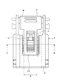
このコネクタのロック構造は、第1コネクタハウジング110及び第2コネクタハウジング120の一対のコネクタハウジングで構成されるコネクタ100において、コネクタハウジング相互の嵌合が完了したときにこれらのコネクタハウジング相互の嵌合状態をロックしたり、あるいはロック状態に有るコネクタハウジング相互を離脱させるためにロック状態を解除したりする構造である。
(1) 嵌合する一対のコネクタハウジングの内の一方のコネクタハウジングには、コネクタハウジング相互の嵌合完了時に他方のコネクタハウジング上のロック用係合部と係合してコネクタハウジング相互の嵌合状態をロックするロックアームと、該ロックアームに一体に形成されて前記ロックアームをロック解除方向に撓み変位させることが可能なロック解除アームと、を備えるコネクタのロック構造であって、
前記ロックアームは、端子金具を収容する端子収容部の後端寄りの上部の外表面から前方に向けて延出し、
前記ロック解除アームは、前記ロックアームの上方にて前記ロックアームの占有幅の範囲内に収まるように、前記ロックアームの前端部から後方に向けて延出し、
前記ロック解除アームの延出端部には、幅方向両側にて前記ロックアームの占有幅の範囲からはみ出す幅寸法を有すると共に後方へ向けて延出する操作部が、一体で設けられ、
前記操作部の幅方向両側端部には、前記ロックアームの後端寄りの部分を幅方向に挟んで向かい合うように下方に向けて延びる一対の支点部であって下端面に前記端子収容部の上部の外表面に当接可能な支点を有する一対の支点部が、一体で設けられ、
前記ロック解除アーム及び前記操作部は、前記端子収容部の外周を覆う略筒状のフード部の上部に設けられた開口部から露呈するように前記フード部内に配置され、
前記ロック解除アームは、前記開口部を構成する開口縁の一部である、前記ロック解除アームの幅寸法に対応する第1の間隔を有して幅方向に対向すると共に前後方向に延びる一対の第1縁部、の間に位置し、
前記操作部は、前記開口部を構成する開口縁の一部である、前記ロック解除アームの幅寸法より大きい前記操作部の幅寸法に対応する前記第1の間隔より大きい第2の間隔を有して幅方向に対向すると共に前記一対の第1縁部より後方側で前後方向に延びる一対の第2縁部、の間に位置していることを特徴とするコネクタのロック構造。
(3) 前記ロック解除アームの前端部の上面部には、前端に向かって前記ロック解除アームの肉厚を低減させるテーパ部が形成されたことを特徴とする上記(1)又は(2)に記載のコネクタのロック構造。
前記ロック解除アーム(37)は、前記ロックアーム(36)の上方に配備されたことを特徴とするコネクタのロック構造。
36 ロックアーム
37 ロック解除アーム
375 テーパ部
Claims (3)
- 嵌合する一対のコネクタハウジングの内の一方のコネクタハウジングには、コネクタハウジング相互の嵌合完了時に他方のコネクタハウジング上のロック用係合部と係合してコネクタハウジング相互の嵌合状態をロックするロックアームと、該ロックアームに一体に形成されて前記ロックアームをロック解除方向に撓み変位させることが可能なロック解除アームと、を備えるコネクタのロック構造であって、
前記ロックアームは、端子金具を収容する端子収容部の後端寄りの上部の外表面から前方に向けて延出し、
前記ロック解除アームは、前記ロックアームの上方にて前記ロックアームの占有幅の範囲内に収まるように、前記ロックアームの前端部から後方に向けて延出し、
前記ロック解除アームの延出端部には、幅方向両側にて前記ロックアームの占有幅の範囲からはみ出す幅寸法を有すると共に後方へ向けて延出する操作部が、一体で設けられ、
前記操作部の幅方向両側端部には、前記ロックアームの後端寄りの部分を幅方向に挟んで向かい合うように下方に向けて延びる一対の支点部であって下端面に前記端子収容部の上部の外表面に当接可能な支点を有する一対の支点部が、一体で設けられ、
前記ロック解除アーム及び前記操作部は、前記端子収容部の外周を覆う略筒状のフード部の上部に設けられた開口部から露呈するように前記フード部内に配置され、
前記ロック解除アームは、前記開口部を構成する開口縁の一部である、前記ロック解除アームの幅寸法に対応する第1の間隔を有して幅方向に対向すると共に前後方向に延びる一対の第1縁部、の間に位置し、
前記操作部は、前記開口部を構成する開口縁の一部である、前記ロック解除アームの幅寸法より大きい前記操作部の幅寸法に対応する前記第1の間隔より大きい第2の間隔を有して幅方向に対向すると共に前記一対の第1縁部より後方側で前後方向に延びる一対の第2縁部、の間に位置していることを特徴とするコネクタのロック構造。 - 前記ロック解除アームは、前記ロックアームの直上に配備されたことを特徴とする請求項1に記載のコネクタのロック構造。
- 前記ロック解除アームの前端部の上面部には、前端に向かって前記ロック解除アームの肉厚を低減させるテーパ部が形成されたことを特徴とする請求項1又は2に記載のコネクタのロック構造。
Priority Applications (3)
| Application Number | Priority Date | Filing Date | Title |
|---|---|---|---|
| JP2015005242A JP6335805B2 (ja) | 2015-01-14 | 2015-01-14 | コネクタのロック構造 |
| US14/994,276 US9780489B2 (en) | 2015-01-14 | 2016-01-13 | Lock structure of connector |
| CN201610024223.0A CN105789979B (zh) | 2015-01-14 | 2016-01-14 | 连接器的锁定构造 |
Applications Claiming Priority (1)
| Application Number | Priority Date | Filing Date | Title |
|---|---|---|---|
| JP2015005242A JP6335805B2 (ja) | 2015-01-14 | 2015-01-14 | コネクタのロック構造 |
Publications (3)
| Publication Number | Publication Date |
|---|---|
| JP2016131112A JP2016131112A (ja) | 2016-07-21 |
| JP2016131112A5 JP2016131112A5 (ja) | 2016-12-28 |
| JP6335805B2 true JP6335805B2 (ja) | 2018-05-30 |
Family
ID=56368189
Family Applications (1)
| Application Number | Title | Priority Date | Filing Date |
|---|---|---|---|
| JP2015005242A Active JP6335805B2 (ja) | 2015-01-14 | 2015-01-14 | コネクタのロック構造 |
Country Status (3)
| Country | Link |
|---|---|
| US (1) | US9780489B2 (ja) |
| JP (1) | JP6335805B2 (ja) |
| CN (1) | CN105789979B (ja) |
Families Citing this family (10)
| Publication number | Priority date | Publication date | Assignee | Title |
|---|---|---|---|---|
| JP6417370B2 (ja) * | 2016-07-29 | 2018-11-07 | 矢崎総業株式会社 | コネクタ |
| JP6653232B2 (ja) * | 2016-09-12 | 2020-02-26 | 矢崎総業株式会社 | コネクタ |
| US10116090B2 (en) * | 2017-03-17 | 2018-10-30 | Hosiden Corporation | Female connector and connection structure of female connector and male connector |
| US10855025B2 (en) | 2017-05-01 | 2020-12-01 | J.S.T. Corporation | Connector position assurance device, connector system and method for operating the connector system |
| US10454209B2 (en) | 2017-05-01 | 2019-10-22 | J.S.T. Corporation | Connector position assurance device, a connector apparatus having male and female connector assemblies with connector position assurance device, a male connector assembly, a female connector assembly, and a method for assembling the connector apparatus |
| US10283904B2 (en) * | 2017-08-04 | 2019-05-07 | Yazaki Corporation | Connector |
| CN109616829B (zh) * | 2017-10-04 | 2020-04-24 | 矢崎总业株式会社 | 连接器 |
| JP7096128B2 (ja) * | 2018-10-16 | 2022-07-05 | 矢崎総業株式会社 | コネクタ |
| JP7286086B2 (ja) * | 2019-07-31 | 2023-06-05 | 日本圧着端子製造株式会社 | コネクタ用ハウジング、及びコネクタ用ハウジングの製造方法 |
| JP7111770B2 (ja) * | 2020-05-29 | 2022-08-02 | 矢崎総業株式会社 | コネクタのロック構造 |
Family Cites Families (12)
| Publication number | Priority date | Publication date | Assignee | Title |
|---|---|---|---|---|
| US4272145A (en) * | 1979-10-22 | 1981-06-09 | Ford Motor Company | Connector lock release |
| US4273403A (en) * | 1980-02-01 | 1981-06-16 | Ford Motor Company | Locking structure for electrical connectors |
| JP2593897Y2 (ja) * | 1988-10-14 | 1999-04-19 | 古河電気工業株式会社 | コネクタユニットのロック装置 |
| JPH1140262A (ja) * | 1997-07-22 | 1999-02-12 | Yazaki Corp | コネクタ |
| JP4035678B2 (ja) * | 1998-11-10 | 2008-01-23 | 矢崎総業株式会社 | ロック構造 |
| JP2001250636A (ja) * | 2000-03-03 | 2001-09-14 | Yazaki Corp | コネクタのロック構造 |
| DE10317154B4 (de) * | 2002-04-15 | 2009-03-26 | Yazaki Corp. | Verriegelungsaufbau für Steckverbinder |
| JP3963849B2 (ja) * | 2003-02-26 | 2007-08-22 | 矢崎総業株式会社 | コネクタのロック構造 |
| JP4844304B2 (ja) | 2006-09-05 | 2011-12-28 | 住友電装株式会社 | コネクタ |
| JP5212284B2 (ja) * | 2009-07-08 | 2013-06-19 | 住友電装株式会社 | コネクタ |
| JP5985164B2 (ja) | 2011-09-07 | 2016-09-06 | 矢崎総業株式会社 | コネクタのロック構造 |
| US8678846B2 (en) | 2012-03-28 | 2014-03-25 | Tyco Electronics Corporation | Electrical connector with connector position assurance device |
-
2015
- 2015-01-14 JP JP2015005242A patent/JP6335805B2/ja active Active
-
2016
- 2016-01-13 US US14/994,276 patent/US9780489B2/en active Active
- 2016-01-14 CN CN201610024223.0A patent/CN105789979B/zh active Active
Also Published As
| Publication number | Publication date |
|---|---|
| CN105789979B (zh) | 2018-12-11 |
| JP2016131112A (ja) | 2016-07-21 |
| CN105789979A (zh) | 2016-07-20 |
| US9780489B2 (en) | 2017-10-03 |
| US20160204551A1 (en) | 2016-07-14 |
Similar Documents
| Publication | Publication Date | Title |
|---|---|---|
| JP6335805B2 (ja) | コネクタのロック構造 | |
| JP6865725B2 (ja) | コネクタ | |
| JP4285376B2 (ja) | レバー式コネクタ | |
| JP4844304B2 (ja) | コネクタ | |
| JP5486859B2 (ja) | コネクタ | |
| JP6364822B2 (ja) | 光トランシーバ | |
| JP6914232B2 (ja) | コネクタ構造 | |
| KR102647188B1 (ko) | 커넥터 장치 | |
| US9564708B2 (en) | Electrical connector | |
| JP6209356B2 (ja) | コネクタ | |
| JP4062250B2 (ja) | コネクタ | |
| JP2019133758A (ja) | コネクタ | |
| JP6475489B2 (ja) | コネクタ | |
| JP6377467B2 (ja) | 電気コネクタ | |
| JP5626118B2 (ja) | コネクタ | |
| WO2021010262A1 (ja) | コネクタ | |
| JP2007059130A (ja) | ロック装置 | |
| JP2019212486A (ja) | コネクタ | |
| JP6150053B2 (ja) | コネクタ | |
| JP6055370B2 (ja) | シールドコネクタ | |
| JP2009054518A (ja) | ロック機能付電気コネクタ | |
| JP4655997B2 (ja) | コネクタ | |
| EP3651284A1 (en) | Connector | |
| JP4075769B2 (ja) | コネクタ | |
| JP4881797B2 (ja) | 電気コネクタ |
Legal Events
| Date | Code | Title | Description |
|---|---|---|---|
| A521 | Request for written amendment filed |
Free format text: JAPANESE INTERMEDIATE CODE: A523 Effective date: 20161114 |
|
| A977 | Report on retrieval |
Free format text: JAPANESE INTERMEDIATE CODE: A971007 Effective date: 20161128 |
|
| A131 | Notification of reasons for refusal |
Free format text: JAPANESE INTERMEDIATE CODE: A131 Effective date: 20161213 |
|
| A521 | Request for written amendment filed |
Free format text: JAPANESE INTERMEDIATE CODE: A523 Effective date: 20170130 |
|
| A131 | Notification of reasons for refusal |
Free format text: JAPANESE INTERMEDIATE CODE: A131 Effective date: 20170411 |
|
| A521 | Request for written amendment filed |
Free format text: JAPANESE INTERMEDIATE CODE: A523 Effective date: 20170601 |
|
| A02 | Decision of refusal |
Free format text: JAPANESE INTERMEDIATE CODE: A02 Effective date: 20171205 |
|
| A521 | Request for written amendment filed |
Free format text: JAPANESE INTERMEDIATE CODE: A523 Effective date: 20180305 |
|
| A911 | Transfer to examiner for re-examination before appeal (zenchi) |
Free format text: JAPANESE INTERMEDIATE CODE: A911 Effective date: 20180313 |
|
| TRDD | Decision of grant or rejection written | ||
| A01 | Written decision to grant a patent or to grant a registration (utility model) |
Free format text: JAPANESE INTERMEDIATE CODE: A01 Effective date: 20180403 |
|
| A61 | First payment of annual fees (during grant procedure) |
Free format text: JAPANESE INTERMEDIATE CODE: A61 Effective date: 20180501 |
|
| R150 | Certificate of patent or registration of utility model |
Ref document number: 6335805 Country of ref document: JP Free format text: JAPANESE INTERMEDIATE CODE: R150 |
|
| R250 | Receipt of annual fees |
Free format text: JAPANESE INTERMEDIATE CODE: R250 |
|
| R250 | Receipt of annual fees |
Free format text: JAPANESE INTERMEDIATE CODE: R250 |
|
| R250 | Receipt of annual fees |
Free format text: JAPANESE INTERMEDIATE CODE: R250 |
|
| S531 | Written request for registration of change of domicile |
Free format text: JAPANESE INTERMEDIATE CODE: R313531 |
|
| R350 | Written notification of registration of transfer |
Free format text: JAPANESE INTERMEDIATE CODE: R350 |
|
| R250 | Receipt of annual fees |
Free format text: JAPANESE INTERMEDIATE CODE: R250 |