EP1362979A2 - Sonde pour mesurer la forme d'un tube - Google Patents
Sonde pour mesurer la forme d'un tube Download PDFInfo
- Publication number
- EP1362979A2 EP1362979A2 EP03011228A EP03011228A EP1362979A2 EP 1362979 A2 EP1362979 A2 EP 1362979A2 EP 03011228 A EP03011228 A EP 03011228A EP 03011228 A EP03011228 A EP 03011228A EP 1362979 A2 EP1362979 A2 EP 1362979A2
- Authority
- EP
- European Patent Office
- Prior art keywords
- pipeline
- pig body
- distance measuring
- measuring means
- pig
- Prior art date
- Legal status (The legal status is an assumption and is not a legal conclusion. Google has not performed a legal analysis and makes no representation as to the accuracy of the status listed.)
- Withdrawn
Links
Images


Classifications
-
- E—FIXED CONSTRUCTIONS
- E21—EARTH DRILLING; MINING
- E21B—EARTH DRILLING, e.g. DEEP DRILLING; OBTAINING OIL, GAS, WATER, SOLUBLE OR MELTABLE MATERIALS OR A SLURRY OF MINERALS FROM WELLS
- E21B47/00—Survey of boreholes or wells
- E21B47/02—Determining slope or direction
- E21B47/024—Determining slope or direction of devices in the borehole
-
- G—PHYSICS
- G01—MEASURING; TESTING
- G01B—MEASURING LENGTH, THICKNESS OR SIMILAR LINEAR DIMENSIONS; MEASURING ANGLES; MEASURING AREAS; MEASURING IRREGULARITIES OF SURFACES OR CONTOURS
- G01B7/00—Measuring arrangements characterised by the use of electric or magnetic techniques
- G01B7/28—Measuring arrangements characterised by the use of electric or magnetic techniques for measuring contours or curvatures
- G01B7/281—Measuring arrangements characterised by the use of electric or magnetic techniques for measuring contours or curvatures for measuring contour or curvature along an axis, e.g. axial curvature of a pipeline or along a series of feeder rollers
-
- G—PHYSICS
- G01—MEASURING; TESTING
- G01C—MEASURING DISTANCES, LEVELS OR BEARINGS; SURVEYING; NAVIGATION; GYROSCOPIC INSTRUMENTS; PHOTOGRAMMETRY OR VIDEOGRAMMETRY
- G01C21/00—Navigation; Navigational instruments not provided for in groups G01C1/00 - G01C19/00
- G01C21/10—Navigation; Navigational instruments not provided for in groups G01C1/00 - G01C19/00 by using measurements of speed or acceleration
- G01C21/12—Navigation; Navigational instruments not provided for in groups G01C1/00 - G01C19/00 by using measurements of speed or acceleration executed aboard the object being navigated; Dead reckoning
- G01C21/16—Navigation; Navigational instruments not provided for in groups G01C1/00 - G01C19/00 by using measurements of speed or acceleration executed aboard the object being navigated; Dead reckoning by integrating acceleration or speed, i.e. inertial navigation
- G01C21/183—Compensation of inertial measurements, e.g. for temperature effects
- G01C21/188—Compensation of inertial measurements, e.g. for temperature effects for accumulated errors, e.g. by coupling inertial systems with absolute positioning systems
Definitions
- the present invention relates to an apparatus (commonly called "an inspection pig") that travels in a pipeline and inspects the inside of the pipeline and a method therefor.
- an inspection pig that travels in a pipeline and inspects the inside of the pipeline and a method therefor.
- the invention relates to a pipeline shape measuring apparatus for measuring the construction shape and the cross-sectional shape of the pipeline with high accuracy and a method therefor.
- the linear shape of the pipeline is measured by means of the in-pipe inspection pig, it is performed by measuring a change in the absolute position or in the relative position of a pig body when the pig body travels in the pipeline.
- the pig body is placed in the pipe (metal pipe) of the pipeline, it is difficult to perform the measurement by detecting a signal from the outside (magnetism of the earth, electromagnetic signal and electromagnetic wave signal from the outside) and a self-contained position measuring system is required.
- a gyroscope unit (pig body) is placed in the pipeline, to measure the orientation of the gyroscope unit, with respect to an earth coordinate system when the pig body travels, and the position of the pipeline with respect to the earth coordinate system is calculated by the traveling distance of the pig body and by the orientation of the gyroscope unit.
- a mechanical gyroscope unit or an optical fiber gyroscope unit has been having a problem in the stability and in the accuracy of the gyroscope sensor itself. So, they cannot achieve the measurement of the linear shape of the pipeline with sufficiently high accuracy. However, the measurement of the linear shape has been achieved with sufficiently high accuracy by the use of a recently developed ring laser gyroscope (RLG).
- RLG ring laser gyroscope
- the linear shape of the pipeline is determined from the direction of the pig body with respect to the earth coordinate system determined from the measuring orientation of the gyroscope and the traveling distance of a roller type distance measuring unit the pig body measured by in contact with the inside surface of the pipeline.
- the orientation of the pig body with respect to the pipeline changes and in particular, temporarily changes to the degree of a large amount when the pig body passes over a bend, so that an error occurs in the calculation of the linear shape.
- the error in the measurement caused by the change in the position of the pig body invites a shift in direction in the later calculation of the linear shape and is accumulated and in particular, in measuring long distance, the accumulated errors become very large.
- a correction to the accumulated errors is made, based on the known positions such as the starting point and the terminal position of the pig body. But in case those errors are caused in the correction range by a plurality of changes in the position of the pig body, it is difficult to correct accurately. Furthermore, in order to correct accurately, it is required to make a position correct at a plurality of positions. But in case of adapting to the pipelines buried in the ground or adapting to the bottom of the sea, it is difficult to make a position correct at a plurality of positions.
- the error correcting methods include a method in which a gyroscope and an acceleration sensor are mounted and in which measurement results by the acceleration sensor are integrated to determine a travel distance in the coordinate system of the gyroscope (acceleration sensor) thereby to calculate the linear shape of the pipeline (position of the gyroscope).
- the pipeline inspecting pig usually produces complex motions such as vibration, rotation around an axis when it travels in the pipe. Therefore, in some case, it is impossible to calculate the linear shape of the pipeline with sufficiently high accuracy from the integration of the measured results by the acceleration sensor.
- a method is considered to measure the orientation of the gyroscope (pig body) in the pipe of the pipeline, and to make a correction. That is, a method in which an optical wave distance measuring unit or an ultrasonic distance measuring unit is placed on the outer periphery of the pig body, in order to measure a distance to the inside surface of the pipe. In this way, measuring the orientation of the pig body in the pipe of the pipeline brings up a correction.
- the optical wave distance-measuring unit raises problems that it cannot be applied to a liquid pipeline for petroleum or the like. It cannot be used even for a gas pipeline, because it is soiled.
- the ultrasonic distance-measuringunit raises a problem that it is difficult to measure the linear shape in a stable way and in an accurate way, because of a change in the speed of the sound or the like.
- a method of measuring a distance by the use of a distance-measuring unit so called an eddy current type
- the eddy current type distance measuring unit raises a problem that measured values are changed by variations in a positional relationship between the distance measuring unit and the peripheral metal (pipe).
- the unit raises a problem in the stability of the distance-measuring unit itself.
- the present invention has been made in view of these circumstances described above. It is the object of the invention to provide an apparatus for measuring the shape of a pipeline, in which the orientation of a pig body in the pipe of the pipeline is measured surely and in a stable way, in order to correct errors caused by measuring the linear shape of the pipeline by means of the gyroscope thereby to realize a correct measurement of the linear shape of the pipeline and a method therefor, and to provide an apparatus for measuring the shape of the pipeline that measures the cross-sectional shape of the pipeline at positions along the pipeline and a method therefor.
- a first means for achieving the above-mentioned object is an apparatus for measuring the shape of a pipeline that travels in the pipeline and measures the shape of the pipeline. And the apparatus provides the following;
- the distance measuring means is the contact type distance measuring means having the mechanism that is mounted on the pig body and always keeps contact with the inside surface of the pipeline. Therefore, it does not raise a problem caused in a case where an optical wave distance measuring unit, an ultrasonic distance measuring unit, or an eddy current type distance measuring unit is used, but can correctly detect the orientation of the pig body in the pipeline.
- an optical wave distance measuring unit, an ultrasonic distance measuring unit, or an eddy current type distance measuring unit is used, but can correctly detect the orientation of the pig body in the pipeline.
- the distance measuring means is the contact type distance measuring means having the mechanism that is mounted on the pig body and always keeps contact with the inside surface of the pipeline. Therefore, it does not raise a problem caused in a case where an optical wave distance measuring unit, an ultrasonic distance measuring unit, or an eddy current type distance measuring unit is used, but can correctly detect the orientation of the pig body in the pipeline.
- the direction of the centerline of the pipeline in combination with the output of the gyro
- a second means for achieving the object described above is the first means characterized in that the contact type distance measuring means includes: a rod (arm), one end of which is connected to a pivot shaft mounted on the outer surface of the pig body; a mechanism for applying a force to the rod (arm) such that the other end of the rod (arm) is always expanded in the radial direction of the pig body (in the direction that faces inside the pipeline) ; and a mechanism for measuring the rotational angle of the rod (arm) around the pivot shaft.
- the other end of the rod (arm) is always expanded in the direction that faces inside the pipeline and hence is put into contact with the inside surface of the pipeline.
- the rotational angle around the pivot shaft of the rod (arm) is measured in this state, it becomes possible to correctly detect a distance between the pig body and the inside surface of the pipeline.
- a third means for achieving the object is the second means characterized in that the mechanism for measuring the rotational angle of the rod (arm) around the pivot shaft is an electromagnetic induction type sleeve sensor connected to the rod (arm).
- a method of directly measuring the rotational angle of the pivot shaft by means of a rotary encoder is also considered to be the method of detecting the rotational angle around the pivot shaft of the rod.
- this method is thought to be unable to provide necessary accuracy because of the accuracy of the mechanical parts and like and will make the mechanism larger. Therefore, in the present means, the electromagnetic induction type sleeve sensor connected to the rod detects the rotation around the pivot shaft of the rod.
- the electromagnetic induction type sleeve sensor measures the position of a sleeve (metal cylinder) moving on a straight line with respect to a coil and has a simple structure, accuracy and stability as a sensor for measuring a displacement in the linear motion. Moreover, this measuring part is mounted on the outside surface of the pig body and hence needs not to be affected by fluid (gas, petroleum or the like) in the pipeline.
- the electromagnetic induction type sleeve sensor is excellent also in this point because it is little affected by the fluid and its temperature.
- a fourth means for achieving the object is the second means characterized in that the other end of the rod (arm) has a wheel.
- the distance measuring means is put into contact with the inside surface of the pipeline via the wheel.
- the mechanical parts of the distance measuring means will be worn or damaged.
- a fifth means for achieving the object is the fourth means characterized in that the contact type distance measuring means has a mechanism for holding the pig body in the pipeline.
- the inspection pig receives the pressure of the fluid flowing in the pipeline, being traveled in the pipeline, it uses a sealing cup for receiving the pressure. And the body of the inspection pig is held by the sealing cup so as to keep a predetermined position with respect to the pipe.
- the present means is especially effective in case that a self-propelled apparatus for measuring the shape of the pipeline that does not use this kind of sealing cup. Further, the present means is effective also in case that, because of some circumstances , it becomes impossible to provide the sealing cup with strength capable of bearing the self-weight of the apparatus for measuring the shape of the pipeline.
- the present means is effective also in case that a plurality of bodies are coupled to each other, one of them is a driving body with the sealing cup, and the other bodies are driven bodies supported by a unit other than the sealing cup.
- the mechanism part of the distance measuring means bears the self-weight of the apparatus for measuring the shape of the pipeline and supports the body in the pipeline.
- the present means does not need a special body holding unit in addition to the distance measuring means and hence can simplify the construction.
- a sixth means for achieving the object is the fourth means or the fifth means characterized in that a function for measuring the travel distance of the pig body in provided by the use of the sensor for detecting the rotation of the wheel.
- the mechanism part of the distance measuring means detects the rotation of the wheel provided on a part in contact with the inside surface of the pipeline to function as an odometer for measuring the travel distance of the pig body. Therefore, the present means eliminates the need for providing a special sensor mechanism for the distance measuring means and thus simplifies the construction correspondingly.
- a seventh means for achieving the object is any one of the first means to the sixth means characterized by a circumferential welded portion detecting means for detecting the circumferential welded portion of the pipeline.
- the traveling distance measuring means Various types of devices such as an odometer are considered as the traveling distance measuring means. However, it is inevitable that any one of them accumulates errors while it travels a long distance and finally causes a large error.
- the pipeline when the pipeline is constructed, the lengths of the respective pipes constituting the pipeline are measured and stored as design specifications. Therefore, by detecting the circumferential welded portion of the pipeline, it is possible to correct the measurement errors of the traveling distance measuring means and hence to calculate a correct travel distance.
- An eighth means for achieving the object is the seventh means characterized in that the circumferential welded portion detecting means has a function of detecting the circumferential welded portion of the pipeline based on the output of the distance measuring means.
- An inside bead is formed on the circumferential welded portion.
- the distance measuring means measures the distance between the body and the inside wall of the pipeline, it detects an abrupt change in the measured distance when it passes the inside bead.
- the measurement results of the distance measuring means provided at the same position decrease by on the order of 1 to 2 mm at the same time, it becomes possible to determine that the distance measuring means pass a convex portion (bead portion) at a welded seam of the pipe.
- the distance measuring means it is possible to detect the circumferential welded portion.
- a ninth means for achieving the object is the seventh means or the eight means characterized in that the traveling distance measuring means has a function of correcting the measurement results based on the output of the circumferential welded portion detecting means.
- the traveling distance measuring means itself has the function of correcting the measurement results based on the output of the circumferential welded portion detecting means.
- the present means provides a correct travel distance as its output.
- a tenth means for achieving the object is the seventh means or the eight means characterized in that the recording means records the output of the circumferential welded portion detecting means.
- the detection result of the circumferential welded portion is recorded in the recording means.
- the present means can correct the output of the traveling distance measuring means by the detection result of the circumferential welded portion at a later stage of analyzing data.
- An eleventh means for achieving the object is any one of the first means to the tenth means characterized by further including a calculating unit for calculating the linear shape of the pipeline from measured data and recording means for recording at least the calculated linear shape of the pipeline in place of the recording means for recording the measurement result of the gyroscope sensor unit, the measurement result of the distance measuring means, and the measurement result of the traveling distance measuring means.
- the measurement of the linear shape of the pipeline can be performed while the inspection apparatus travels in the pipeline.
- the present means eliminates the need for offline calculating the linear shape reformed later and hence is efficient.
- a twelfth means for achieving the object is any one of the first means to the eleventh means characterized by further including orientation change preventing means that is mounted at the appropriate position of the outer surface of the pig body and prevents an extreme orientation change of the pig body, with respect to the pipeline, that is caused when the pig body passes over the bend of the pipeline.
- the orientation change preventing means mounted at the appropriate position of the outer surface of the pig body prevents the extreme orientation change of the pig body with respect to the pipeline.
- a thirteenth means for achieving the object is the twelfth means characterized in that the orientation change preventing means is a disc that is made of a soft material and mounted on the pig body and has a diameter smaller than the inside diameter of the pipe of the pipeline.
- the disc that is made of the soft material and mounted on the pig body contacts the inside surface of the pipe of the pipeline to prevent the orientation of the pig body with respect to the pipe from being extremely changed thereby to prevent the pig body from contacting with the inside surface of the pipe.
- the disc is made of the soft material such as resin and is easily deformed, so that the disc does not reduce the pig body's ability of passing the bend.
- a fourteenth means for achieving the object is the twelfth means characterized in that the position change preventing means has a position holding member mounted on the pig body and shaped like a sealing cup.
- the position holding member mounted on the pig body and shaped like the sealing cup contacts the inside surface of the pipe and prevents the orientation of the pig body with respect to the pipe from being extremely changed thereby to prevent the pig body from contacting the inside surface of the pipe.
- the position holding member shaped like the sealing cup is easily deformed, so that the disc does not reduce the pig body's ability of passing the bend.
- a fifteenth means for achieving the object is a method for measuring the shape of the pipeline by traveling in the pipeline by the use of the apparatus as described in any one of the first means to the fourteenth means and characterized by calculating the linear shape of the pipeline from necessary data among data recorded in the recording means.
- a sixteenth means for achieving the object is a method for measuring the shape of the pipeline by traveling in the pipeline by use of the apparatus as described in any one of the first means to the fourteenth means and characterized by calculating the inside cross-sectional shape of the pipeline at respective position from necessary data among data recorded in the recording means.
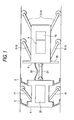
- FIG. 1 schematically shows an apparatus for measuring a shape of a pipeline that is one embodiment of the invention.
- sealing cups 3 are provided on the outer periphery of a pig body 1.
- the outer periphery of each sealing cup 3 is put into close contact with the inside surface of the pipe.
- a force for driving the pig body 1 is generated by a pressure difference before and behind the sealing cup 3 to drive the pig body 1 in the pipe.
- the sealing cups 3 are provided at two positions of the pig body 1. If the sealing cup 3 is provided at one position, there is a possibility that the deformation of the sealing cup 3 will produce a gap between the sealing cup 3 and the inside surface of the pipe, when the pig body 1 travels. The possibility will interfere with smooth travel of the pig body 1. Thus, in order to eliminate this possibility, there are provided two sealing cups 3.
- a disc 35 made of resin and having an outside diameter smaller than the inside diameter of the pipe of the pipeline is mounted on the front of the pig body 2. This disc 35 prevents the orientation of the pig body 2 with respect to the pipe from being extremely changed when the pig body 2 passes a bend.
- the disc 35 is mounted only on the front of the pig body 2 in the embodiment shown in Fig. 1, the disc 35 can also be mounted on the rear of the pig body 2.
- a sealing cup can be used, in place of the disc, that is similar to the sealing cup 3 mounted on the pig body 1.
- the outside diameter of the sealing cup is made to be a little smaller than the inside diameter of the pipe, to make a gap between the sealing cup and the pipe.
- a hole is made to be in the sealing cup to an extent that does not reduce its strength thereby, to prevent the sealing cup from producing a larger propelling force. Without this hole, there happens a possibility that a large propelling force, which is different from the pulling force of the pig body 1, will be applied on the pig body 2 to impair the smooth travel of the pig body 2.
- Traveling distance-measuring means 17, 18 are mounted on the outside of the pig body 1.
- the traveling distance measuring means 17 (18) is a rod having a pivot shaft on the outside surface of the pig body 2.
- the traveling distance measuring means has a wheel on its other end and has a mechanism in which the wheel at the tip of the rod is always in contact with the inside surface of the pipeline. The wheel at the tip rotates when the pig body 1 travels in the pipeline.
- measuring the number of revolutions of the wheel makes it possible to calculate the traveling distance of the pig body 1 from the outer peripheral length of the wheel.
- two pieces of traveling distance-measuring means (17, 18) are mounted at opposite positions. This is because when the traveling distance measuring means passes the bend, travel distance measured by two traveling distance measuring means are different from each other, depending on the contact positions of the wheels in the circumferential direction of the pipe (depending on an inside position or an outside position in the bend of the pipe), so that the measured different travel distances are averaged to calculate the travel distance of the pig body. It is also possible to increase the number of traveling distance-measuring means, so as to improve accuracy to a further degree.
- the measured values of the traveling distance measuring means are sent via a cable 22 to a signal processing and recording unit 19 mounted in the pig body 2 and recorded.
- a battery 20 in the pig body 1 supplies an electric power to the traveling distance measuring means 17, 18 and also supplies the electric power via the cable 22 to units mounted in the pig body 2.
- the pig body 2 is connected via a connection part 21 to the pig body 1 and, when the pig body 1 is driven, travels in the pipe in cooperation with the pig body 1.
- the pig body 1 is separated from the pig body 2 for the purpose of ensuring the pig body to smoothly pass the bend in the pipeline (in order to prevent the body from contacting the inside surface of the pipe).
- one piece of pig body 1 can be provided, if conditions are permitted, which are determined by the inside diameter of the pipe and the radius of curvature of the bend.
- a three-axis gyroscope sensor unit 4 is placed in the pig body 2 such that one measuring axis of the gyroscope sensor unit is parallel to the center axis of the pig body 2 and is fixed in such a way that the gyroscope sensor unit is not shifted in relative position from the pig body 2 when the pig body 2 travels.
- Two sets of six direction distance measuring means 5-10 and 11-16 are mounted on the outer periphery of the pig body 2 at two positions in the back and forth direction (in the traveling direction).
- the six distances measuring means of each set are located at equal intervals in a circumferential direction.
- the distance measuring means 5-10 and 11-16 are called sensor units of distance measuring means in the claims, but for the sake of convenience of description, the sensor unit is called distance measuring means.
- a reference numeral 30 denotes a rod
- 31 denotes a contact wheel
- 32 denotes an electromagnetic induction type sleeve sensor
- 33 denotes a linkage for connecting the sleeve sensor 32 to the rod
- 34 denotes a pivot shaft of the rod 30.
- Fig. 2A is a schematic view of the distance measuring means 5-10, when viewed from the front. As shown in the drawing, the distance measuring means 5-10 are arranged at intervals of 60° in the circumferential direction of the pig body 2 and the contact wheels 31 mounted on the tips of the rods 30 are in contact with the inside peripheral surface of the pipeline.
- Fig. 2 schematically shows the mechanism of each distance measuring means.
- the distance measuring means has the contact wheel 31 that is mounted on the tip of the rod 30 and contacts the inside surface of the pipe and rotates around the pivot shaft 34 on the pig body side.
- the linkage 33 is coupled to one end of the rod 30 and the rotation of the rod 30 is transmitted to the sensor rod 32a of the electromagnetic sleeve sensor 32 via the linkage 33.
- a force is always applied to the rod 30 by a spring or the like such that the rod 30 is expanded in the inside peripheral direction of the pipeline. This applied force is also used for holding the position of the pig body 2 in the pipeline.
- Fig.2B shows one example of configuration of the distance measuring means and another configuration including the rod and sleeve sensor can also be used.
- the respective measured data of the three-axis gyroscope sensor unit 4, the traveling distance measuring means 17, 18, the distance measuring means 5-16 are inputted to the signal processing and recording device 19.
- the data is recorded and stored at a predetermined period in the signal processing and recording device 19 and the stored data is read after the pig body finishes traveling and the calculation of the linear shape of the pipeline is performed from the stored data.
- the signal-processing device it is also possible for the signal-processing device to perform the calculation of the linear shape of the pipeline in real time and to record the data of the linear shape in the recording device.
- FIG. 3 A principle of the measurement of the linear shape of the pipeline in the embodiment of the invention will be described with reference to Fig. 3 and Fig. 4.
- Fig. 3 assume that two sets of four distance measuring means are provided at each of positions A and B, the position A being away from the position B by a distance L in the direction of travel of the pig body, and that the four distance measuring means of each set are arranged in four directions perpendicular to each other in the circumferential direction, so that there are provided a total of eight distance measuring means.
- a center axis in the direction of travel of the gyroscope sensor is Z-axis and that the directions of measurement of the distance measuring means in a cross section perpendicular to the direction of travel are X-axis and Y-axis.
- measured distances to the inside surface of the pipe measured by the respective distance measuring means are XA1, XA2, YA1, YA2, XB1 XB2, YB1, and YB2.
- the respective distance measuring means are arranged at equal distances from the Z-axis (center axis) of the pig body.
- the direction of length (center axis) of the pipe is the z-axis
- a vertical direction in the cross section of the pipe is y-axis
- a horizontal direction in the cross section of the pipe is x-axis.
- the pig body travels in the pipe in a position in which the center axis (Z-axis) of the pig body and the center axis (z-axis) of the pipe is tilted (rotated) at an angle of ⁇ x around the X-axis.
- the travel of the pig body is viewed from the coordinate system of the pipe (x-y-z coordinate system)
- the pig body travels along the z-axis, but when viewed from the coordinate system of the pig body (three-axis gyroscope sensor unit) (X-Y-Z coordinate system)
- the pig body travels in the direction of not only the Z-axis but also the Y-axis.
- the traveling distance in the Z-Y coordinates of the pig body can be calculated from the traveling distance of the pig body along the z-axis (pipe).
- the gyroscope sensor of the pig body can measure the direction of its own coordinate system with respect to an absolute coordinate system (earth coordinate system).
- an absolute coordinate system earth coordinate system
- two sets of six pieces of distance measuring means are used, which are arranged on the circumference of the pig body 2.
- the rectangular coordinate system (X-Y-Z coordinate system) at the point A or the point B is determined and that a positional relationship between the center of the pig body and the center of the pipeline is determined from the measurement results at the six points.
- the distance measuring means for measuring the distance to the inside surface of the pipe are arranged on the outer periphery of the pig body in four directions perpendicular to each other. However, if three or more distance measuring means are provided at equal intervals in the circumferential direction, it is possible to calculate the angle of the center axis of the pig body with respect to the center axis of the pipe.
- FIG. 4 A method of measuring a deviation in angle of the center axis of the pig body from the center axis of the pipeline by the use of the distance measuring means shown in Fig. 2 will be shown in Fig. 4.
- the length of a first rod be L1
- the length of a second rod be L2
- a distance between the pivot shafts on the pig body side of the first rod and the second rod be L0
- angles of the rods with respect to the pig body be ⁇ 1 and ⁇ 2.
- an apparatus and a method for measuring the shape of a pipeline in which the orientation of the pig body in the pipe of the pipeline can, surely, be in a stable way, measured to correct errors arising in the measurement of the linear shape of the pipeline by the use of the gyroscope thereby to realize a correct measurement of the linear shape of the pipeline, and an apparatus and a method for measuring the sectional shape of the pipeline at positions of the pipeline.
Applications Claiming Priority (4)
| Application Number | Priority Date | Filing Date | Title |
|---|---|---|---|
| JP2002143102 | 2002-05-17 | ||
| JP2002143102 | 2002-05-17 | ||
| JP2003075901A JP3855951B2 (ja) | 2002-05-17 | 2003-03-19 | パイプラインの形状計測装置及び方法 |
| JP2003075901 | 2003-03-19 |
Publications (2)
| Publication Number | Publication Date |
|---|---|
| EP1362979A2 true EP1362979A2 (fr) | 2003-11-19 |
| EP1362979A3 EP1362979A3 (fr) | 2004-04-28 |
Family
ID=29272405
Family Applications (1)
| Application Number | Title | Priority Date | Filing Date |
|---|---|---|---|
| EP03011228A Withdrawn EP1362979A3 (fr) | 2002-05-17 | 2003-05-16 | Sonde pour mesurer la forme d'un tube |
Country Status (4)
| Country | Link |
|---|---|
| US (1) | US20030233894A1 (fr) |
| EP (1) | EP1362979A3 (fr) |
| JP (1) | JP3855951B2 (fr) |
| CA (1) | CA2428551A1 (fr) |
Cited By (10)
| Publication number | Priority date | Publication date | Assignee | Title |
|---|---|---|---|---|
| GB2410070A (en) * | 2004-01-16 | 2005-07-20 | Weatherford Lamb | Preventing rotation of pipeline tools |
| WO2005116401A1 (fr) * | 2004-05-28 | 2005-12-08 | Deutsche Montan Technologie Gmbh | Dispositif d'inspection de trous de forage et de montage de moyens d'ancrage |
| US7421914B2 (en) | 2004-09-20 | 2008-09-09 | Weatherford/Lamb, Inc. | Caliper apparatus |
| WO2009001022A1 (fr) * | 2007-06-27 | 2008-12-31 | Petróleo Brasileiro S A - Petrobras | Racleur de profilage pour détecter et quantifier la corrosion interne dans des tuyaux |
| DE102009059717A1 (de) * | 2009-11-30 | 2011-06-30 | Rosen Swiss Ag | Molch |
| CN105300244A (zh) * | 2015-09-17 | 2016-02-03 | 北汽福田汽车股份有限公司 | 一种软管内径测量仪 |
| CN107976152A (zh) * | 2017-10-12 | 2018-05-01 | 上海交通大学 | 用于检测管状体外壁形貌的ccd的位置调节装置 |
| CN108180883A (zh) * | 2017-12-20 | 2018-06-19 | 北京华航无线电测量研究所 | 一种大变形的变形内检测器 |
| WO2022055524A1 (fr) * | 2020-09-11 | 2022-03-17 | Saudi Arabian Oil Company | Profileur de canalisation |
| US11493464B2 (en) * | 2016-05-26 | 2022-11-08 | Rocsole Ltd | Determining an electrical property of interest of materials in a target region |
Families Citing this family (37)
| Publication number | Priority date | Publication date | Assignee | Title |
|---|---|---|---|---|
| US7159477B2 (en) * | 2002-03-13 | 2007-01-09 | Borealis Technology Oy | Apparatus for inspecting deformation of pipes |
| JP4013820B2 (ja) * | 2003-04-30 | 2007-11-28 | Jfeエンジニアリング株式会社 | パイプラインの形状計測評価方法 |
| US7493817B2 (en) * | 2005-06-23 | 2009-02-24 | Operations Technology Development, Nfp | Underground pipe inspection device and method |
| US7551197B2 (en) * | 2005-09-08 | 2009-06-23 | Ulc Robotics, Inc. | Pipeline inspection system |
| JP4866989B2 (ja) * | 2006-02-06 | 2012-02-01 | 多摩川精機株式会社 | 孔路計測方法及び装置 |
| WO2007121772A1 (fr) * | 2006-04-20 | 2007-11-01 | Freyssinet | Procede et machine pour revetir un tuyau |
| JP2008076907A (ja) * | 2006-09-22 | 2008-04-03 | Jfe Engineering Kk | パイプラインの3次元プロファイルを求める方法、パイプラインの埋設位置特定方法、パイプラインの欠陥位置特定方法 |
| US8417423B2 (en) * | 2007-04-23 | 2013-04-09 | David G. Fudala | Robotic platform for collecting data to emulate material handling vehicle mast angles |
| US8994527B2 (en) * | 2009-03-19 | 2015-03-31 | Galen G. Verhulst | Sea floor sampling device and method |
| JP5252641B2 (ja) * | 2009-03-30 | 2013-07-31 | 学校法人大同学園 | 孔形状測定方法 |
| KR101065955B1 (ko) | 2010-02-16 | 2011-09-19 | 주식회사 제노프릭스 | 원형 구멍의 3차원 형상 측정 시스템 |
| KR101305961B1 (ko) | 2011-12-13 | 2013-09-26 | 전자부품연구원 | 비파괴 검사 장치 및 이의 운용 방법 |
| KR101334351B1 (ko) | 2012-05-31 | 2013-11-29 | 삼성중공업 주식회사 | 배관의 좌굴 감지 장치 |
| CN103063114B (zh) * | 2012-12-19 | 2015-12-23 | 天津市联众钢管有限公司 | 一种钢管自动通径机 |
| US9488006B2 (en) * | 2014-02-14 | 2016-11-08 | Baker Hughes Incorporated | Downhole depth measurement using tilted ribs |
| CN104266664B (zh) * | 2014-09-28 | 2017-10-17 | 中国石油天然气股份有限公司 | 一种管道中心线测量的螺旋误差补偿方法及测量设备 |
| WO2016069412A2 (fr) * | 2014-10-27 | 2016-05-06 | Gagemaker, Lp | Calibrage de l'alésage de stator |
| US10036680B2 (en) | 2015-03-19 | 2018-07-31 | General Electric Company | Pipeline sensor carrier |
| US9921123B2 (en) * | 2015-03-27 | 2018-03-20 | Water Resources Facilities & Maintenance Co., Ltd. | Pipe mapping probe apparatus for searching pipe route position |
| CN106324438A (zh) * | 2016-10-19 | 2017-01-11 | 成都亚联科科技有限公司 | 一种电力检修用移动式高压电缆检测装置 |
| KR101748095B1 (ko) * | 2016-12-19 | 2017-06-14 | 한국가스공사 | 배관 내경 측정장치 및 방법 |
| CN107192354B (zh) * | 2017-06-30 | 2019-06-14 | 广船国际有限公司 | 一种管路弯角测量装置 |
| KR102040585B1 (ko) * | 2017-12-29 | 2019-11-06 | 한국가스공사 | 배관 검사 장치 및 그 동작방법 |
| CN108458932B (zh) * | 2018-04-20 | 2019-11-19 | 大连理工大学 | 一种利用电磁感应技术测量砂砾料动态三轴试样局部变形的方法 |
| KR102001971B1 (ko) * | 2018-07-10 | 2019-07-19 | (주)태경이엔씨 | 유간 측정 장치 |
| CN109115084B (zh) * | 2018-09-18 | 2024-04-16 | 南京信息职业技术学院 | 一种深盲孔内径自动测量装置及测量方法 |
| CN109282726B (zh) * | 2018-10-18 | 2024-04-16 | 南京信息职业技术学院 | 一种自主测量深孔内径的检测装置 |
| CN109115215B (zh) * | 2018-10-29 | 2023-09-15 | 唐山市中宇科技发展有限公司 | 惯性导航定位测量全能轮系系统 |
| RU2693039C1 (ru) * | 2018-11-26 | 2019-07-01 | Публичное акционерное общество "Транснефть" (ПАО "Транснефть") | Калибровочное устройство |
| US10947794B2 (en) | 2019-03-01 | 2021-03-16 | Saudi Arabian Oil Company | Method and system for extended reach coiled tubing |
| US11320549B2 (en) * | 2020-05-22 | 2022-05-03 | Carl Israel Larkin | Vibrating pipe locator |
| CN111735491A (zh) * | 2020-05-14 | 2020-10-02 | 国网浙江宁波市鄞州区供电有限公司 | 一种测量准确的电缆管道检测装置 |
| CN113028200A (zh) * | 2021-03-14 | 2021-06-25 | 郑州大学 | 一种基于激光测距的管道定位机器人 |
| CN113048326A (zh) * | 2021-03-14 | 2021-06-29 | 郑州大学 | 一种基于机器视觉的管道内缺陷检测机器人 |
| CN113236904B (zh) * | 2021-06-25 | 2023-03-24 | 中国人民解放军63653部队 | 一种管道测量机器人 |
| CN113970285B (zh) * | 2021-11-04 | 2024-04-05 | 上海机电工程研究所 | 火工弹射作动筒内腔体直径测量装置及其测量方法 |
| CN114812436B (zh) * | 2022-05-27 | 2023-03-24 | 水利部交通运输部国家能源局南京水利科学研究院 | 在役埋地运行大口径管道椭圆度测量装置及使用方法 |
Citations (4)
| Publication number | Priority date | Publication date | Assignee | Title |
|---|---|---|---|---|
| US3882606A (en) * | 1973-05-16 | 1975-05-13 | Amf Inc | Method and apparatus for measuring curvature and curvature variations in pipelines and the like |
| US4524526A (en) * | 1982-11-22 | 1985-06-25 | Litton Systems, Inc. | Apparatus and method for inertial measurement of pipeline deflection |
| US4945775A (en) * | 1988-12-30 | 1990-08-07 | Pulsearch Consolidated Technology Ltd. | Inertial based pipeline monitoring system |
| US6108921A (en) * | 1997-06-12 | 2000-08-29 | Pipetronix Gmbh | Scraper for determining the position of pipelines |
Family Cites Families (12)
| Publication number | Priority date | Publication date | Assignee | Title |
|---|---|---|---|---|
| IT998126B (it) * | 1973-06-04 | 1976-01-20 | Snam Progetti | Dispositivo per il rilievo in con tinuo della ovalizzazione e delle proiezioni su due piani ortogonali della deformata di tubazioni som merse |
| US3968568A (en) * | 1974-07-10 | 1976-07-13 | Amf Incorporated | Encoder error correction means for use with a distance measuring wheel |
| JPS5812984B2 (ja) * | 1975-06-24 | 1983-03-11 | 日本電子株式会社 | シツリヨウブンセキソウチ |
| GB1592616A (en) * | 1977-06-21 | 1981-07-08 | Coal Ind | Bunkering system |
| JPS6021321B2 (ja) * | 1979-01-16 | 1985-05-27 | 関西電力株式会社 | 地中埋設管の有効内径の計測方法並びにその装置 |
| DE3008701A1 (de) * | 1980-03-07 | 1981-09-24 | Johann 7057 Leutenbach Hess | Winkelmessvorrichtung fuer abkantpressen |
| JPS59112218A (ja) * | 1982-12-20 | 1984-06-28 | Oyo Chishitsu Kk | 孔壁測定方法及びそれに用いる測定装置 |
| US4859848A (en) * | 1987-10-09 | 1989-08-22 | Masstron, Inc. | Mass spectrometer apparatus |
| JPH0741414U (ja) * | 1993-12-28 | 1995-07-21 | 日立電線株式会社 | 埋設管路計測装置の支持装置 |
| US5457841A (en) * | 1994-10-13 | 1995-10-17 | Continental Emsco Company | Cleaning pig for pipeline of varying diameter |
| CA2443217C (fr) * | 2001-04-02 | 2009-12-22 | Tokyo Gas Co., Ltd. | Methode et dispositif de mesure du diametre interieur d'une canalisation |
| JP3635490B2 (ja) * | 2001-10-15 | 2005-04-06 | Jfeエンジニアリング株式会社 | 管体のプロファイル測定方法及び装置、並びに管体の応力測定方法 |
-
2003
- 2003-03-19 JP JP2003075901A patent/JP3855951B2/ja not_active Expired - Lifetime
- 2003-05-12 US US10/437,124 patent/US20030233894A1/en not_active Abandoned
- 2003-05-13 CA CA002428551A patent/CA2428551A1/fr not_active Abandoned
- 2003-05-16 EP EP03011228A patent/EP1362979A3/fr not_active Withdrawn
Patent Citations (5)
| Publication number | Priority date | Publication date | Assignee | Title |
|---|---|---|---|---|
| US3882606A (en) * | 1973-05-16 | 1975-05-13 | Amf Inc | Method and apparatus for measuring curvature and curvature variations in pipelines and the like |
| US4524526A (en) * | 1982-11-22 | 1985-06-25 | Litton Systems, Inc. | Apparatus and method for inertial measurement of pipeline deflection |
| US4945775A (en) * | 1988-12-30 | 1990-08-07 | Pulsearch Consolidated Technology Ltd. | Inertial based pipeline monitoring system |
| US4945775B1 (en) * | 1988-12-30 | 2000-05-02 | Nowsco Well Service Ltd | Inertial based pipeline monitoring system |
| US6108921A (en) * | 1997-06-12 | 2000-08-29 | Pipetronix Gmbh | Scraper for determining the position of pipelines |
Cited By (13)
| Publication number | Priority date | Publication date | Assignee | Title |
|---|---|---|---|---|
| GB2410070A (en) * | 2004-01-16 | 2005-07-20 | Weatherford Lamb | Preventing rotation of pipeline tools |
| WO2005116401A1 (fr) * | 2004-05-28 | 2005-12-08 | Deutsche Montan Technologie Gmbh | Dispositif d'inspection de trous de forage et de montage de moyens d'ancrage |
| AU2005248043B2 (en) * | 2004-05-28 | 2010-05-13 | Dmt Gmbh & Co. Kg | Device for examining rotor drilled holes |
| US7421914B2 (en) | 2004-09-20 | 2008-09-09 | Weatherford/Lamb, Inc. | Caliper apparatus |
| WO2009001022A1 (fr) * | 2007-06-27 | 2008-12-31 | Petróleo Brasileiro S A - Petrobras | Racleur de profilage pour détecter et quantifier la corrosion interne dans des tuyaux |
| DE102009059717A1 (de) * | 2009-11-30 | 2011-06-30 | Rosen Swiss Ag | Molch |
| CN105300244A (zh) * | 2015-09-17 | 2016-02-03 | 北汽福田汽车股份有限公司 | 一种软管内径测量仪 |
| US11493464B2 (en) * | 2016-05-26 | 2022-11-08 | Rocsole Ltd | Determining an electrical property of interest of materials in a target region |
| CN107976152A (zh) * | 2017-10-12 | 2018-05-01 | 上海交通大学 | 用于检测管状体外壁形貌的ccd的位置调节装置 |
| CN107976152B (zh) * | 2017-10-12 | 2020-02-18 | 上海交通大学 | 用于检测管状体外壁形貌的ccd的位置调节装置 |
| CN108180883A (zh) * | 2017-12-20 | 2018-06-19 | 北京华航无线电测量研究所 | 一种大变形的变形内检测器 |
| WO2022055524A1 (fr) * | 2020-09-11 | 2022-03-17 | Saudi Arabian Oil Company | Profileur de canalisation |
| US11859754B2 (en) | 2020-09-11 | 2024-01-02 | Saudi Arabian Oil Company | Pipeline profiler |
Also Published As
| Publication number | Publication date |
|---|---|
| JP3855951B2 (ja) | 2006-12-13 |
| CA2428551A1 (fr) | 2003-11-17 |
| JP2004045374A (ja) | 2004-02-12 |
| EP1362979A3 (fr) | 2004-04-28 |
| US20030233894A1 (en) | 2003-12-25 |
Similar Documents
| Publication | Publication Date | Title |
|---|---|---|
| EP1362979A2 (fr) | Sonde pour mesurer la forme d'un tube | |
| JP6549116B2 (ja) | 装置の配向を計算するためのシステムおよび方法 | |
| GB2088554A (en) | Pipeline route surveying device | |
| CN103697886A (zh) | 管道中心线的惯性导航测量方法 | |
| JP2007155584A (ja) | 慣性航法システム | |
| WO2020065659A1 (fr) | Robot sphérique pour inspection interne de pipelines | |
| KR101821658B1 (ko) | 수평유지회전부 및 중력 기울기 센서를 이용한 지중관로 곡률반경 측정시스템 및 이를 이용한 측정방법 | |
| EP3901510B1 (fr) | Piston détecteur-enregistreur de déformations géométriques pour détecter les déformations géométriques d'un pipeline | |
| WO2014096942A2 (fr) | Outil intelligent pour la détection de perforations, d'écailles et de bosses dans des conduites de transport | |
| CN107255478A (zh) | 一种小径管道缺陷检测定位用惯性传感器选型方法 | |
| JP3635490B2 (ja) | 管体のプロファイル測定方法及び装置、並びに管体の応力測定方法 | |
| JP2007263689A (ja) | 外部情報を得られない環境における装置の方位計測方法 | |
| McGregor et al. | Determining position and orientation of a 3-wheel robot on a pipe using an accelerometer | |
| JP4013820B2 (ja) | パイプラインの形状計測評価方法 | |
| CN212300305U (zh) | 一种三维测量仪 | |
| JPH037884B2 (fr) | ||
| GB2327759A (en) | Pipeline leak detector system | |
| US20220018484A1 (en) | Systems and methods for travel distance measurement | |
| JP2006118972A (ja) | パイプラインの形状計測評価方法及びその装置 | |
| RU2772550C1 (ru) | Многоканальная измерительная система для измерения геометрического профиля трубопровода | |
| JP2006118971A (ja) | パイプラインの形状計測評価方法及びその装置 | |
| JP2001349846A (ja) | 管内検査装置の円周方向角度検出方法 | |
| CN112033339A (zh) | 一种三维测量仪及测量方法 | |
| JP2010025856A (ja) | 球体の非接触式3軸角速度計測法 | |
| JPH09145355A (ja) | ジョイント角の測定方法およびその装置 |
Legal Events
| Date | Code | Title | Description |
|---|---|---|---|
| PUAI | Public reference made under article 153(3) epc to a published international application that has entered the european phase |
Free format text: ORIGINAL CODE: 0009012 |
|
| AK | Designated contracting states |
Kind code of ref document: A2 Designated state(s): AT BE BG CH CY CZ DE DK EE ES FI FR GB GR HU IE IT LI LU MC NL PT RO SE SI SK TR |
|
| AX | Request for extension of the european patent |
Extension state: AL LT LV MK |
|
| PUAL | Search report despatched |
Free format text: ORIGINAL CODE: 0009013 |
|
| AK | Designated contracting states |
Kind code of ref document: A3 Designated state(s): AT BE BG CH CY CZ DE DK EE ES FI FR GB GR HU IE IT LI LU MC NL PT RO SE SI SK TR |
|
| AX | Request for extension of the european patent |
Extension state: AL LT LV MK |
|
| RIC1 | Information provided on ipc code assigned before grant |
Ipc: 7G 01C 21/16 B Ipc: 7G 01B 7/28 A |
|
| AKX | Designation fees paid | ||
| REG | Reference to a national code |
Ref country code: DE Ref legal event code: 8566 |
|
| STAA | Information on the status of an ep patent application or granted ep patent |
Free format text: STATUS: THE APPLICATION IS DEEMED TO BE WITHDRAWN |
|
| 18D | Application deemed to be withdrawn |
Effective date: 20041029 |