EP1362931B9 - Method and apparatus for fabrication of a DLC layer system - Google Patents
Method and apparatus for fabrication of a DLC layer system Download PDFInfo
- Publication number
- EP1362931B9 EP1362931B9 EP03014612A EP03014612A EP1362931B9 EP 1362931 B9 EP1362931 B9 EP 1362931B9 EP 03014612 A EP03014612 A EP 03014612A EP 03014612 A EP03014612 A EP 03014612A EP 1362931 B9 EP1362931 B9 EP 1362931B9
- Authority
- EP
- European Patent Office
- Prior art keywords
- layer
- carbon
- substrate
- gas
- plasma
- Prior art date
- Legal status (The legal status is an assumption and is not a legal conclusion. Google has not performed a legal analysis and makes no representation as to the accuracy of the status listed.)
- Expired - Lifetime
Links
Images


Classifications
-
- H—ELECTRICITY
- H01—ELECTRIC ELEMENTS
- H01J—ELECTRIC DISCHARGE TUBES OR DISCHARGE LAMPS
- H01J37/00—Discharge tubes with provision for introducing objects or material to be exposed to the discharge, e.g. for the purpose of examination or processing thereof
- H01J37/32—Gas-filled discharge tubes
- H01J37/32009—Arrangements for generation of plasma specially adapted for examination or treatment of objects, e.g. plasma sources
- H01J37/32055—Arc discharge
-
- C—CHEMISTRY; METALLURGY
- C23—COATING METALLIC MATERIAL; COATING MATERIAL WITH METALLIC MATERIAL; CHEMICAL SURFACE TREATMENT; DIFFUSION TREATMENT OF METALLIC MATERIAL; COATING BY VACUUM EVAPORATION, BY SPUTTERING, BY ION IMPLANTATION OR BY CHEMICAL VAPOUR DEPOSITION, IN GENERAL; INHIBITING CORROSION OF METALLIC MATERIAL OR INCRUSTATION IN GENERAL
- C23C—COATING METALLIC MATERIAL; COATING MATERIAL WITH METALLIC MATERIAL; SURFACE TREATMENT OF METALLIC MATERIAL BY DIFFUSION INTO THE SURFACE, BY CHEMICAL CONVERSION OR SUBSTITUTION; COATING BY VACUUM EVAPORATION, BY SPUTTERING, BY ION IMPLANTATION OR BY CHEMICAL VAPOUR DEPOSITION, IN GENERAL
- C23C14/00—Coating by vacuum evaporation, by sputtering or by ion implantation of the coating forming material
- C23C14/22—Coating by vacuum evaporation, by sputtering or by ion implantation of the coating forming material characterised by the process of coating
- C23C14/34—Sputtering
- C23C14/35—Sputtering by application of a magnetic field, e.g. magnetron sputtering
-
- C—CHEMISTRY; METALLURGY
- C23—COATING METALLIC MATERIAL; COATING MATERIAL WITH METALLIC MATERIAL; CHEMICAL SURFACE TREATMENT; DIFFUSION TREATMENT OF METALLIC MATERIAL; COATING BY VACUUM EVAPORATION, BY SPUTTERING, BY ION IMPLANTATION OR BY CHEMICAL VAPOUR DEPOSITION, IN GENERAL; INHIBITING CORROSION OF METALLIC MATERIAL OR INCRUSTATION IN GENERAL
- C23C—COATING METALLIC MATERIAL; COATING MATERIAL WITH METALLIC MATERIAL; SURFACE TREATMENT OF METALLIC MATERIAL BY DIFFUSION INTO THE SURFACE, BY CHEMICAL CONVERSION OR SUBSTITUTION; COATING BY VACUUM EVAPORATION, BY SPUTTERING, BY ION IMPLANTATION OR BY CHEMICAL VAPOUR DEPOSITION, IN GENERAL
- C23C16/00—Chemical coating by decomposition of gaseous compounds, without leaving reaction products of surface material in the coating, i.e. chemical vapour deposition [CVD] processes
- C23C16/02—Pretreatment of the material to be coated
- C23C16/0272—Deposition of sub-layers, e.g. to promote the adhesion of the main coating
- C23C16/029—Graded interfaces
-
- C—CHEMISTRY; METALLURGY
- C23—COATING METALLIC MATERIAL; COATING MATERIAL WITH METALLIC MATERIAL; CHEMICAL SURFACE TREATMENT; DIFFUSION TREATMENT OF METALLIC MATERIAL; COATING BY VACUUM EVAPORATION, BY SPUTTERING, BY ION IMPLANTATION OR BY CHEMICAL VAPOUR DEPOSITION, IN GENERAL; INHIBITING CORROSION OF METALLIC MATERIAL OR INCRUSTATION IN GENERAL
- C23C—COATING METALLIC MATERIAL; COATING MATERIAL WITH METALLIC MATERIAL; SURFACE TREATMENT OF METALLIC MATERIAL BY DIFFUSION INTO THE SURFACE, BY CHEMICAL CONVERSION OR SUBSTITUTION; COATING BY VACUUM EVAPORATION, BY SPUTTERING, BY ION IMPLANTATION OR BY CHEMICAL VAPOUR DEPOSITION, IN GENERAL
- C23C16/00—Chemical coating by decomposition of gaseous compounds, without leaving reaction products of surface material in the coating, i.e. chemical vapour deposition [CVD] processes
- C23C16/22—Chemical coating by decomposition of gaseous compounds, without leaving reaction products of surface material in the coating, i.e. chemical vapour deposition [CVD] processes characterised by the deposition of inorganic material, other than metallic material
- C23C16/26—Deposition of carbon only
-
- C—CHEMISTRY; METALLURGY
- C23—COATING METALLIC MATERIAL; COATING MATERIAL WITH METALLIC MATERIAL; CHEMICAL SURFACE TREATMENT; DIFFUSION TREATMENT OF METALLIC MATERIAL; COATING BY VACUUM EVAPORATION, BY SPUTTERING, BY ION IMPLANTATION OR BY CHEMICAL VAPOUR DEPOSITION, IN GENERAL; INHIBITING CORROSION OF METALLIC MATERIAL OR INCRUSTATION IN GENERAL
- C23C—COATING METALLIC MATERIAL; COATING MATERIAL WITH METALLIC MATERIAL; SURFACE TREATMENT OF METALLIC MATERIAL BY DIFFUSION INTO THE SURFACE, BY CHEMICAL CONVERSION OR SUBSTITUTION; COATING BY VACUUM EVAPORATION, BY SPUTTERING, BY ION IMPLANTATION OR BY CHEMICAL VAPOUR DEPOSITION, IN GENERAL
- C23C28/00—Coating for obtaining at least two superposed coatings either by methods not provided for in a single one of groups C23C2/00 - C23C26/00 or by combinations of methods provided for in subclasses C23C and C25C or C25D
- C23C28/04—Coating for obtaining at least two superposed coatings either by methods not provided for in a single one of groups C23C2/00 - C23C26/00 or by combinations of methods provided for in subclasses C23C and C25C or C25D only coatings of inorganic non-metallic material
- C23C28/044—Coating for obtaining at least two superposed coatings either by methods not provided for in a single one of groups C23C2/00 - C23C26/00 or by combinations of methods provided for in subclasses C23C and C25C or C25D only coatings of inorganic non-metallic material coatings specially adapted for cutting tools or wear applications
-
- C—CHEMISTRY; METALLURGY
- C23—COATING METALLIC MATERIAL; COATING MATERIAL WITH METALLIC MATERIAL; CHEMICAL SURFACE TREATMENT; DIFFUSION TREATMENT OF METALLIC MATERIAL; COATING BY VACUUM EVAPORATION, BY SPUTTERING, BY ION IMPLANTATION OR BY CHEMICAL VAPOUR DEPOSITION, IN GENERAL; INHIBITING CORROSION OF METALLIC MATERIAL OR INCRUSTATION IN GENERAL
- C23C—COATING METALLIC MATERIAL; COATING MATERIAL WITH METALLIC MATERIAL; SURFACE TREATMENT OF METALLIC MATERIAL BY DIFFUSION INTO THE SURFACE, BY CHEMICAL CONVERSION OR SUBSTITUTION; COATING BY VACUUM EVAPORATION, BY SPUTTERING, BY ION IMPLANTATION OR BY CHEMICAL VAPOUR DEPOSITION, IN GENERAL
- C23C28/00—Coating for obtaining at least two superposed coatings either by methods not provided for in a single one of groups C23C2/00 - C23C26/00 or by combinations of methods provided for in subclasses C23C and C25C or C25D
- C23C28/04—Coating for obtaining at least two superposed coatings either by methods not provided for in a single one of groups C23C2/00 - C23C26/00 or by combinations of methods provided for in subclasses C23C and C25C or C25D only coatings of inorganic non-metallic material
- C23C28/046—Coating for obtaining at least two superposed coatings either by methods not provided for in a single one of groups C23C2/00 - C23C26/00 or by combinations of methods provided for in subclasses C23C and C25C or C25D only coatings of inorganic non-metallic material with at least one amorphous inorganic material layer, e.g. DLC, a-C:H, a-C:Me, the layer being doped or not
-
- C—CHEMISTRY; METALLURGY
- C23—COATING METALLIC MATERIAL; COATING MATERIAL WITH METALLIC MATERIAL; CHEMICAL SURFACE TREATMENT; DIFFUSION TREATMENT OF METALLIC MATERIAL; COATING BY VACUUM EVAPORATION, BY SPUTTERING, BY ION IMPLANTATION OR BY CHEMICAL VAPOUR DEPOSITION, IN GENERAL; INHIBITING CORROSION OF METALLIC MATERIAL OR INCRUSTATION IN GENERAL
- C23C—COATING METALLIC MATERIAL; COATING MATERIAL WITH METALLIC MATERIAL; SURFACE TREATMENT OF METALLIC MATERIAL BY DIFFUSION INTO THE SURFACE, BY CHEMICAL CONVERSION OR SUBSTITUTION; COATING BY VACUUM EVAPORATION, BY SPUTTERING, BY ION IMPLANTATION OR BY CHEMICAL VAPOUR DEPOSITION, IN GENERAL
- C23C28/00—Coating for obtaining at least two superposed coatings either by methods not provided for in a single one of groups C23C2/00 - C23C26/00 or by combinations of methods provided for in subclasses C23C and C25C or C25D
- C23C28/04—Coating for obtaining at least two superposed coatings either by methods not provided for in a single one of groups C23C2/00 - C23C26/00 or by combinations of methods provided for in subclasses C23C and C25C or C25D only coatings of inorganic non-metallic material
- C23C28/048—Coating for obtaining at least two superposed coatings either by methods not provided for in a single one of groups C23C2/00 - C23C26/00 or by combinations of methods provided for in subclasses C23C and C25C or C25D only coatings of inorganic non-metallic material with layers graded in composition or physical properties
-
- C—CHEMISTRY; METALLURGY
- C23—COATING METALLIC MATERIAL; COATING MATERIAL WITH METALLIC MATERIAL; CHEMICAL SURFACE TREATMENT; DIFFUSION TREATMENT OF METALLIC MATERIAL; COATING BY VACUUM EVAPORATION, BY SPUTTERING, BY ION IMPLANTATION OR BY CHEMICAL VAPOUR DEPOSITION, IN GENERAL; INHIBITING CORROSION OF METALLIC MATERIAL OR INCRUSTATION IN GENERAL
- C23C—COATING METALLIC MATERIAL; COATING MATERIAL WITH METALLIC MATERIAL; SURFACE TREATMENT OF METALLIC MATERIAL BY DIFFUSION INTO THE SURFACE, BY CHEMICAL CONVERSION OR SUBSTITUTION; COATING BY VACUUM EVAPORATION, BY SPUTTERING, BY ION IMPLANTATION OR BY CHEMICAL VAPOUR DEPOSITION, IN GENERAL
- C23C28/00—Coating for obtaining at least two superposed coatings either by methods not provided for in a single one of groups C23C2/00 - C23C26/00 or by combinations of methods provided for in subclasses C23C and C25C or C25D
- C23C28/40—Coatings including alternating layers following a pattern, a periodic or defined repetition
- C23C28/42—Coatings including alternating layers following a pattern, a periodic or defined repetition characterized by the composition of the alternating layers
-
- B—PERFORMING OPERATIONS; TRANSPORTING
- B82—NANOTECHNOLOGY
- B82Y—SPECIFIC USES OR APPLICATIONS OF NANOSTRUCTURES; MEASUREMENT OR ANALYSIS OF NANOSTRUCTURES; MANUFACTURE OR TREATMENT OF NANOSTRUCTURES
- B82Y30/00—Nanotechnology for materials or surface science, e.g. nanocomposites
-
- F—MECHANICAL ENGINEERING; LIGHTING; HEATING; WEAPONS; BLASTING
- F16—ENGINEERING ELEMENTS AND UNITS; GENERAL MEASURES FOR PRODUCING AND MAINTAINING EFFECTIVE FUNCTIONING OF MACHINES OR INSTALLATIONS; THERMAL INSULATION IN GENERAL
- F16C—SHAFTS; FLEXIBLE SHAFTS; ELEMENTS OR CRANKSHAFT MECHANISMS; ROTARY BODIES OTHER THAN GEARING ELEMENTS; BEARINGS
- F16C33/00—Parts of bearings; Special methods for making bearings or parts thereof
- F16C33/02—Parts of sliding-contact bearings
- F16C33/04—Brasses; Bushes; Linings
- F16C33/043—Sliding surface consisting mainly of ceramics, cermets or hard carbon, e.g. diamond like carbon [DLC]
-
- Y—GENERAL TAGGING OF NEW TECHNOLOGICAL DEVELOPMENTS; GENERAL TAGGING OF CROSS-SECTIONAL TECHNOLOGIES SPANNING OVER SEVERAL SECTIONS OF THE IPC; TECHNICAL SUBJECTS COVERED BY FORMER USPC CROSS-REFERENCE ART COLLECTIONS [XRACs] AND DIGESTS
- Y10—TECHNICAL SUBJECTS COVERED BY FORMER USPC
- Y10T—TECHNICAL SUBJECTS COVERED BY FORMER US CLASSIFICATION
- Y10T428/00—Stock material or miscellaneous articles
- Y10T428/24—Structurally defined web or sheet [e.g., overall dimension, etc.]
- Y10T428/24942—Structurally defined web or sheet [e.g., overall dimension, etc.] including components having same physical characteristic in differing degree
- Y10T428/2495—Thickness [relative or absolute]
- Y10T428/24967—Absolute thicknesses specified
- Y10T428/24975—No layer or component greater than 5 mils thick
-
- Y—GENERAL TAGGING OF NEW TECHNOLOGICAL DEVELOPMENTS; GENERAL TAGGING OF CROSS-SECTIONAL TECHNOLOGIES SPANNING OVER SEVERAL SECTIONS OF THE IPC; TECHNICAL SUBJECTS COVERED BY FORMER USPC CROSS-REFERENCE ART COLLECTIONS [XRACs] AND DIGESTS
- Y10—TECHNICAL SUBJECTS COVERED BY FORMER USPC
- Y10T—TECHNICAL SUBJECTS COVERED BY FORMER US CLASSIFICATION
- Y10T428/00—Stock material or miscellaneous articles
- Y10T428/25—Web or sheet containing structurally defined element or component and including a second component containing structurally defined particles
- Y10T428/252—Glass or ceramic [i.e., fired or glazed clay, cement, etc.] [porcelain, quartz, etc.]
-
- Y—GENERAL TAGGING OF NEW TECHNOLOGICAL DEVELOPMENTS; GENERAL TAGGING OF CROSS-SECTIONAL TECHNOLOGIES SPANNING OVER SEVERAL SECTIONS OF THE IPC; TECHNICAL SUBJECTS COVERED BY FORMER USPC CROSS-REFERENCE ART COLLECTIONS [XRACs] AND DIGESTS
- Y10—TECHNICAL SUBJECTS COVERED BY FORMER USPC
- Y10T—TECHNICAL SUBJECTS COVERED BY FORMER US CLASSIFICATION
- Y10T428/00—Stock material or miscellaneous articles
- Y10T428/26—Web or sheet containing structurally defined element or component, the element or component having a specified physical dimension
- Y10T428/263—Coating layer not in excess of 5 mils thick or equivalent
- Y10T428/264—Up to 3 mils
- Y10T428/265—1 mil or less
-
- Y—GENERAL TAGGING OF NEW TECHNOLOGICAL DEVELOPMENTS; GENERAL TAGGING OF CROSS-SECTIONAL TECHNOLOGIES SPANNING OVER SEVERAL SECTIONS OF THE IPC; TECHNICAL SUBJECTS COVERED BY FORMER USPC CROSS-REFERENCE ART COLLECTIONS [XRACs] AND DIGESTS
- Y10—TECHNICAL SUBJECTS COVERED BY FORMER USPC
- Y10T—TECHNICAL SUBJECTS COVERED BY FORMER US CLASSIFICATION
- Y10T428/00—Stock material or miscellaneous articles
- Y10T428/30—Self-sustaining carbon mass or layer with impregnant or other layer
Definitions
- the present invention relates to a layer system according to claim 1, a method according to claim 10 and a device according to claim 28.
- Preferred embodiments of the invention are disclosed in the dependent claims 2 to 9, 11 to 27 and 29 to 39 and in the description, examples and drawings .
- DLC layers diamond-like carbon layers
- HF high frequency
- Typical wear protection applications include applications in the mechanical engineering sector, such as protection against sliding wear, pitting, cold welding, etc., in particular on components with mutually moving surfaces, such as gears, Pump and bucket tappets, piston rings, injector needles, complete bearing sets or their individual components u.v.a. called, as well as applications in the field of Material processing to protect the tools used for cutting or forming Machining and injection molds.
- inlet layers for example, graphitic carbon and / or a mixture of metal or metal carbide and carbon
- inlet layers could therefore not be taken into account, on the one hand by the Enema effect necessary minimum layer thickness more harmful Strengths were built on the one hand and on the other hand, the liability to clean Carbon layers was problematic. Only such layers can but through the Combination of the very hard carbon layer or diamond layer with it deposited sliding or inlet layer the increasing requirements for components, as required, for example, for individual components in modern engine construction will match.
- EP 87 836 discloses a DLC layer system with a 0.1-49.1% proportion of metallic Components, for example, deposited by means of cathodic sputtering becomes.
- DE 43 43 354 A1 describes a method for producing a multi-layer Ti inconveniencen Layer system with a hard material layer of titanium nitrides titanium carbides and titanium borides and a Reibmindernden C-containing surface layer, wherein the Ti and N content in the direction of the surface is progressively reduced.
- a pulsed plasma jet uses the method described in US 5,078,848 for the production of DLC layers. Due to the directed particle radiation from a Source with a small outlet cross-section, but such methods are only conditionally to uniform coating of larger surfaces.
- EP-A-651 069 describes a friction-reducing wear protection system from 2 to 5000 alternating DLC and SiDLC layers.
- a method for the deposition of a-DLC layers with an Si intermediate layer and subsequent a-SiC: H transition zone for improving the adhesion is described in EP-A-600 533.
- EP-A-885 983 and EP-A-856 592 are various methods of preparation such layers described.
- US 4,728,529 describes a method for the deposition of DLC using an HF plasma in which the layer formation in a pressure range between 103 and 1 mbar from an oxygen-free hydrocarbon plasma, the noble gas or Hydrogen is added takes place.
- DE-C-195 13 614 uses a bipolar substrate voltage with a shorter positive pulse duration in a pressure range between 50-1000 Pa. Thus, layers in the range of 10 nm to 10 microns and a hardness between 15 - 40 GPa deposited.
- a CVD method with substrate voltage generated independently of the coating plasma is described in DE-A-198 26 259, preferably bipolar, but also other Periodic changes in substrate voltages are applied.
- this requires a relative aurwendigen, as to be provided in duplicate, electrical supply unit to carry out the process.
- MeC / C layers with a high C content have proven to be particularly effective, in which the soft cover layer on the one hand achieves an enema effect, and on the other hand, by transferring C particles, a lubricating effect for the entire tribosystem.
- Similar layer combinations with a adhesion enhancing metallic intermediate layer between the hard material layer and the graphitic carbon-containing metal or MeC layer are described in WO 99-55929.
- the article "DLC multilayer coatings for wear protection" by Deng J. et al., Diamond and Related Materials, Elsevier Science Publishers, Amsterdam, NL, vol. 4, no. 7, 15 May 1995, Pp. 936-943 discloses a DLC multilayer coating for wear protection.
- the DLC layer is on a Ti adhesive layer and a multilayer transition layer of a sequence of TiN, TiCN and TiC applied.
- the transitional layer is a complex one Gradient layer in which the nitrogen content decreases and the carbon content to the DLC layer increases.
- the document FR 2 596 775 shows a process for producing a layer system as well as the coating system itself.
- the special plant geometry aims at a possible high ionization of the process gas or metal vapor.
- a third electrode is provided to prevent drifting of electrons to the walls.
- An electron gun is located in the lower part of the housing.
- US 5,709,784 relates to a device for coating by means of a low-voltage arc discharge.
- the device comprises, in addition to the usual components, in particular also a device for applying a Substratbiasschreib to the substrate, as well Helmholtz coils for generating a magnetic field.
- a low-voltage arc process By means of this system can a low-voltage arc process be performed.
- Next to a cathode and an anode is one additional voltage source for generating a positive DC voltage at the anode intended.
- the object of the present invention is relatively thick DLC layer systems to provide with high hardness and excellent adhesion, which also have a sufficiently high conductivity to be deposited without RF bias so that a method and apparatus can be used can, which require little effort and high efficiency for the industrial Use have. Accordingly, it is also an object of the present invention to provide a corresponding method and an apparatus.
- a further object of the invention is to provide a method and a device for producing a DLC sliding layer system according to the invention.
- a DLC layer system according to the invention is achieved by producing a layer with the following layer structure.
- an adhesive layer with at least one element the group of elements of IV, V and VI subgroup as well as Si.
- a Adhesive layer of the elements Cr or Ti used which is particularly suitable for this purpose have proved suitable.
- transition layer which is preferably formed as a gradient layer is, in the course perpendicular to the substrate surface of the metal content - and the C content increases.
- the transition layer essentially comprises carbon and at least one element from the group of elements forming the adhesive layer. Additionally, in a preferred Embodiment be contained hydrogen. In addition, both include Transition layer as well as the adhesive layer unavoidable impurities, as for example given by atoms incorporated into the layer from the surrounding atmosphere are, for example, the noble gases used in the production, such as argon or xenon.
- the increase of the carbon towards the topcoat by increasing, if necessary, different carbide phases, by increasing the free carbon, or by a Mixture of such phases with the metallic phase of the transition layer take place.
- the thickness of the gradient or transition layer can, as known in the art, be set by setting suitable process ramps.
- the increase in C content or decrease of the metallic phase can take place continuously or stepwise, Furthermore, at least in a part of the transition layer, a sequence of metal rich and C-rich monolayers for further degradation of layer stresses become.
- the material properties (For example, modulus of elasticity, structure, etc.) of the adhesive and the final DLC layer substantially continuously matched to each other and thus the danger the crack formation along an otherwise occurring metal or Si / DLC interface counteracted.
- the conclusion of the layer package forms a substantially exclusively of carbon and preferably hydrogen-containing layer, with one compared to the adhesive and transition layer greater layer thickness.
- carbon and hydrogen can also occur here noble gases, such as argon or xenon.
- noble gases such as argon or xenon.
- the hardness of the entire DLC layer system is to a value greater than 15 GPa, preferred greater than or equal to 20 GPa and an adhesive strength better than or equal to HF 3, preferably better or equal to HF 2, in particular equal to HF 1 according to VDI 3824 sheet 4 is reached.
- the Hardness is determined by the Knoop hardness measurement with o, 1 N load, i. HK0,1 correspond.
- the present DLC layer is characterized by the low friction coefficients typical for DLC, preferably ⁇ ⁇ 0.3 in the pin / Scheibetest test, off.
- the layer thicknesses are in total> 1 .mu.m, preferably> 2 .mu.m, wherein the adhesive layer and the transition layer preferably layer thicknesses of 0.05 .mu.m to 1.5 .mu.m, in particular from 0.1 microns to 0.8 microns, while the top layer preferably has a thickness of 0.5 ⁇ m to 20 ⁇ m, in particular 1 ⁇ m to 10 ⁇ m.
- the H content in the outer layer is preferably 5 to 30 atom%, especially 10 to 20 Atom%.
- deposited DLC layer systems according to the invention show fracture surface, unlike conventional DLC layers, not glassy-amorphous but have a fine-grained structure, wherein the grain size preferably ⁇ 300 nm, in particular ⁇ 100 nm.
- the coating shows a multiple lifetime over other DLC layers, such as metal carbon, in particular WC / C layers. So could on a provided with a DLC-layer injector For internal combustion engines in the test after 1000h only a slight wear found whereas, in the same test, a WC / C coated nozzle already appeared after 10 hours Reason for a high surface wear down to the base material precipitated.
- the layer shows due to its Structure and the inventive steps a significantly improved adhesion.
- Conventional layer systems require doping in the functional layer (DLC) to reduce the layer stress, but also reduces the hardness.
- REM fractions of the inventive layer show in contrast to previously known DLC layers containing the typical fracture of an amorphous brittle layer have partly mussel-like eruptions, a fine-grained straight fracture surface.
- Layers with The property profile described above is particularly suitable for applications in the Mechanical engineering, for example for the coating of highly loaded pump or cup tappets and valve trains, cams and camshafts as they are for automotive internal combustion engines and gear are used, but also for the protection of highly loaded Gears, plungers, pump spindles and others. Components in which a special hard and smooth surface with good sliding properties is needed.
- the growth rate of the DLC layer is about 1-3 ⁇ m / h, the layer stress for the whole system at 1-4 GPa and thus in the usual range of hard DLC layers.
- a final, softer, relatively large proportion of graphitic carbon-containing sliding layer can also be advantageously applied to non-inventive DLC layers and layer systems as well as to diamond layers, in particular nanocrystalline diamond layers.
- a DLC sliding layer system according to the invention is described, which advantageously, but by no means restrictively, consists of a DLC layer system as described above with a sliding layer deposited thereon.
- a particularly advantageous embodiment of the friction-reducing layer which is particularly suitable for application to the above-described inventive DLC layer system consists in applying a DLC structure without a metallic additional element, but with an increasing proportion of sp 2 bonds, preferably in a graphitic layer structure Hardness of the top layer reduced, and the sliding and possibly enema properties can be improved.
- Another advantageous embodiment of the sliding layer can take place by forming a second, inverse gradient layer, in which the metal content to the surface increases, but the C content decreases.
- the metal content is increased until the friction coefficient reaches a desired low value.
- one or more metals from the IV, V, VI subgroup, and Si used.
- the metal content of the layers should be between 0.1 and 50 atom%, preferably between 1 and 20 atom%.
- a further preferred embodiment of the friction-reducing layer can be produced by applying a metallic or carbide, in particular a Cr or WC intermediate layer to the layer consisting essentially exclusively of carbon and hydrogen, wherein subsequently again a gradient cover layer formed similarly to the first gradient layer with decreasing metal and increasing C content follows.
- the same or the same metallic elements as in the first gradient layer are used in order to minimize the complexity of the coating apparatus.
- the metal content of the layers should be between 0.1 and 50 atom%, preferably between 1 and 20 atom%.
- metal-containing overlays can also bring about a marked improvement in the performance on conventionally deposited DLC layers.
- One reason for the resulting low impact on the overall adhesion of such systems could be due to the easily adjustable, low additionally introduced layer stresses.
- the hardness of the DLC layer is preferably set to a value greater than 15 GPa, preferably greater than or equal to 20 GPa, the hardness of the overlying softer sliding layer is adjusted as required.
- the integral hydrogen content of the layer system according to the invention is preferably set to a content of between 5 and 30 atom%, in particular between 10 and 20 atom%.
- the layer roughness can be adjusted to a Ra value of less than 0.04, preferably less than 0.01, or an Rz DIN value of less than 0.8, preferably less than 0.5.
- DLC sliding layer system lies in the combination of the high hardness of the DLC layer, coupled with a sliding properties which are again improved by up to one order of magnitude compared with the already good running behavior of the DLC layer.
- DLC layers it is also possible for DLC layers to impart run-in behavior through initial layer removal and graphitic counter-body lubrication, as a result of which the wear of an uncoated counter body can also be significantly reduced.
- a lower Rz or Ra number ie a lower roughness of the coated surfaces, than with conventionally used hard coatings, in particular applied by the Arc method, can be set.
- known hard / overlay combinations can be disturbed by particularly hard roughness peaks often the running of the tribosystem, if not prevented and become, which can lead to the partial or total destruction of the surface of a counter body, especially if it is not itself protected by a hard layer. This is particularly important in tribosystems with high sliding share, such as tilt and slide lever on bucket tappets, different gears, etc. important.
- the superiority of DLC overlay systems has been demonstrated in various applications both over known hard / overlay combinations and over pure DLC layer systems.
- these coatings can also be used advantageously in the tool area, especially for forming (pressing, stamping, deep-drawing, ...) and injection molding tools, but also with certain limitations in the machining of iron materials for cutting tools. in particular if a particularly low coefficient of friction, possibly paired with a defined inlet effect, is desired for the application.
- a polishing effect on the chip discharge surface has already been observed after a single use (a borehole), which is advantageous, for example, for deep hole bores.
- tools can be dispensed with an expensive repolishing the chip flow surfaces.
- DLC sliding layer systems according to the invention can be deposited more smoothly than conventional hard material / lubricant layer combinations (eg TiAlN / / WC / C) deposited with arc evaporators and can be integrated more easily in a continuous process than, for example, likewise known Ti-DLC // MoSx layer combinations.
- conventional hard material / lubricant layer combinations eg TiAlN / / WC / C
- the inventive method for producing the DLC layer system is characterized by the features according to claim 10.
- the parts to be coated are cleaned in particular in a manner known for PVD methods and mounted on a mounting device. Unlike HF methods can do this advantageously holding devices adapted according to particle geometry - 1, 2 or 3 substantially parallel axes of rotation are used, whereby a greater loading density can be achieved.
- the mounting device with the to be coated Parts are brought into the process chamber of a coating plant and after pumping to a starting pressure of less than 10-4 mbar, preferably 10-5 mbar the process sequence is started.
- the first part of the process, cleaning the substrate surfaces is called, for example, Heating process performed to the still adhering to the surface of the parts volatile To remove substances.
- a noble gas plasma is preferably by means of a high current / low voltage discharge between one or more, in one to the process chamber arranged adjacent to the ionization chamber, placed on negative potential filaments and ignited the positive potential set holding devices with the parts. This causes an intense electron bombardment and thus a heating of the parts causes.
- the use of an Ar / H2 mixture has proven to be particularly favorable here, because of the reducing effect of hydrogen at the same time a cleaning effect the part surfaces is achieved.
- the high current / low voltage arc discharge can be variable with a static or advantageously substantially locally be moved magnetic field.
- the ionization chamber described above can also be a hollow cathode or other known ion or electron source used become.
- an etching process can be started as a cleaning process, for example, by a low-voltage arc between the ionization chamber and an auxiliary anode is ignited, and the ions by means of a negative bias voltage of 50-300 V. be pulled on the parts.
- the ions bombard the surface there and remove it remaining impurities. Thus, a clean surface is achieved.
- the process atmosphere may in addition to noble gases, such. Argon also contain hydrogen.
- the etching process is carried out by applying a pulsed substrate bias voltage without or with the support of a low-voltage arc, as just described, wherein a medium frequency bias in the range of 1 to 10,000 kHz, in particular between 20 and 250 kHz is used.
- a preferably metallic, in particular consisting of Cr or Ti adhesive layer with a known PVD or plasma CVD processes for example by means of arc evaporation, different Ionplatingvon, but preferably by cathodic sputtering at least of a target evaporated.
- a applied negative substrate bias voltage To support the vapor deposition on the substrate is a applied negative substrate bias voltage.
- the ion bombardment and the effect of it Layer compaction during the sputtering process can additionally by a parallel operated Low-voltage arc and / or a stabilization or intensification of the plasma applied magnetic field, and / or by applying a DC bias voltage to the substrate or by the application of a middle frequency bias between substrate and process chamber in Range from 1 to 10,000, in particular between 20 to 250 kHz are supported.
- the thickness of the adhesive layer is in a known manner by one of the respective plant geometry appropriate choice of sputtering or evaporation time and power set.
- the application of the transition layer is carried out so that in addition to the plasma-assisted vapor deposition the adhesive layer components at the same time deposited carbon from the gas phase becomes.
- This is preferably done by a plasma CVD method in which a carbon-containing Gas, preferably a hydrocarbon gas, in particular acetylene as the reaction gas is used.
- transition layer a particular "pulsed", Medium frequency applied substrate bias voltage and superimposed on a magnetic field.
- the diamond-like carbon layer then becomes the cover layer produced by plasma CVD deposition of carbon from the gas phase, wherein as the reaction gas, a carbon-containing gas, preferably a carbon dioxide gas, in particular Acetylene is used.
- a substrate bias voltage continues to be applied to the substrate maintain and maintain the superimposed magnetic field.
- reaction gas for the deposition of carbon to form the transition layer and the cover layer of diamond-like Carbon in addition to the carbonaceous gas additionally hydrogen and noble gas, preferably Argon or xenon.
- the set pressure in the process chamber is between 10-4 to 10-2 mbar.
- the proportion of the carbon-containing gas and the proportion of noble gas in particular To lower argon.
- the during the process steps for vapor deposition of the adhesive layer, applying the transition layer and depositing the cap layer on the substrate applied substrate bias voltage can in particular in the formation of the transition layer and the cover layer a Alternating voltage (AC), a DC or superimposed DC voltage (DC) or modulated DC voltage, in particular a unipolar (negative) or bipolar Substratbiasschreib be in a middle frequency range of 1 to 10000 kHz, preferably 20 to 250 kHz is pulsed.
- the pulse shape can be symmetrical, for example sinusoidal, sawtooth, or rectangular or asymmetrical, so long negative and short positive pulse times or large negative and small positive amplitudes applied become.
- a longitudinal Magnetic field set with uniform field line with the magnetic field laterally and / or spatially, continuously or stepwise changeable.
- a DC bias was used to apply the adhesive layer
- a middle frequency generator connected, its sapissersimpulse (regulation via control the introduced power is also possible, but not preferred) in the form of a sinusoidal, or another bi-or unipolar waveform.
- the frequency range used in this case is between 1 to about 10,000 kHz, preferably between 20 and 250 kHz, the amplitude voltage between 100 and 3,000 V, preferably between 500 and 2.500 V.
- the change of the substrate voltage by switching a specially designed for the delivery of DC and medium frequency voltage generator.
- the etching and adhesion coating process a medium frequency voltage to the substrates created.
- a hydrocarbon gas preferably acetylene with a stepwise or preferred continuously rising gas flow is admitted into the recipient.
- the performance of the at least one metallic or Si target stepwise or continuously shut down is preferred up to one, depending on the achieved Hydrocarbon flow shut down by a skilled person at an easily determined minimum power, in the still a stable operation without poisoning by the Reactive gas is possible.
- the at least one target is preferably with a or several movably arranged diaphragms shielded against the process chamber, and shut off. This measure largely prevents occupancy of the target with a DLC layer, with which an otherwise necessary free sputtering between individual DLC coating batches can be waived.
- the next batch to be performed is it sufficient to provide a startup of the at least one target with the shutters closed, again to a completely bare, suitable for the application of the adhesive layer target surface to achieve.
- An essential contribution to the stabilization of the DLC coating process according to the invention is achieved by the formation of a longitudinal magnetic field. This is done - if not already used in the previous process step for applying the adhesive layer - substantially simultaneously with the switching of the substrate voltage to the middle frequency generator.
- the magnetic field is formed so that a possible, uniform field line course is given in the process chamber.
- current is preferably introduced through two electromagnetic coils which essentially bound the process chamber on opposite sides in such a way that a magnetic field which is directed in the same direction and which reinforces one another is formed on both coils. With smaller chamber dimensions, a sufficient effect may also be achieved with only one coil. This achieves an approximately uniform distribution of the medium-frequency plasma over larger chamber volumes.
- sporadic formation of secondary plasmas may still occasionally occur if certain geometric and electromagnetic boundary conditions are fulfilled.
- This can be counteracted by a temporally and spatially variable magnetic field by the coil currents are shifted with each other or preferably against each other.
- the first coil is first flowed through for 120 seconds by a stronger current I than the second coil.
- the current is inverse, ie the second magnetic field is stronger than the first magnetic field.
- the rate of growth depends not only on the process parameters but also on the load and the bracket off. In particular, this affects whether the parts to be coated 1-, Twice or three times rotating, mounted on magnetic mounts, or clamped or plugged become. Also, the total mass and Plasmen misglindikeit the brackets is important for example, with lightly constructed brackets, e.g. through use of Instead of plates made of solid material, higher growth rates and achieved an overall better layer quality.
- the entire process chamber penetrating magnetic field in addition to the longitudinal, the entire process chamber penetrating magnetic field (far field) more local magnetic fields - so-called near fields - are provided.
- the bias voltage is adjusted either stepwise or continuously to a value above 2000 V, preferably between 2000 and 2500 V after applying the pure DLC layer, with otherwise substantially the same or similar set Listeparametem.
- the proportion of carbon atoms growing in graphitic sp 2 bond increases.
- the previously deposited pure DLC layer can be given improved sliding properties.
- an inverse gradient layer can be applied in the simplest case, while retaining the same parameters as in the preceding DLC layer, the process can be carried out with the addition of one or more metallic or metal carbide components.
- the power of the at least one target is increased stepwise or preferably continuously up to a value at which the layer has certain desired layer properties (coefficient of friction,).
- the remaining parameters are preferably left unchanged, but an additional adjustment is possible at any time if desired.
- the process is preferably continued while keeping the setting constant until a desired layer thickness of the inverse gradient layer is reached.
- a further advantageous possibility for forming an inverse gradient layer results if, in addition to or instead of the mentioned hydrocarbon gas, silicon-containing or silicon- and oxygen- or nitrogen-containing gases, for example mono- and disilanes, siloxanes, hexamethyldisiloxane, hexamethyldisilazane, dimethyldiethoxysilane, tetramethysilane, etc
- silicon-containing or silicon- and oxygen- or nitrogen-containing gases for example mono- and disilanes, siloxanes, hexamethyldisiloxane, hexamethyldisilazane, dimethyldiethoxysilane, tetramethysilane, etc
- silicon-containing or silicon- and oxygen- or nitrogen-containing gases for example mono- and disilanes, siloxanes, hexamethyldisiloxane, hexamethyldisilazane, dimethyldiethoxysilane, tetramethysilane,
- a sliding layer as a gradient cover layer can take place either directly on a DLC layer or after application of a metallic or carbide intermediate layer.
- the at least one source used for this purpose is, as described above, but turned on more strongly to 0% lowering of the carbon content of the process gas.
- Carbide or metallic targets can be used to produce the friction-reducing cover layer, with the carbide targets offering the advantage of an overall higher C content, with very high load-bearing capacity of the layers.
- the content of graphitic carbon is in turn adjusted by introducing a C-containing reactive gas, wherein advantageously the gas flow from switching on the targets used to produce the MeC / C layer, or with a time delay, increased by a ramp function and at the end of the coating for a certain time is kept constant.
- a particularly advantageous embodiment of the layer is obtained when a thin (0.01-0.9 ⁇ m) carbidic, such as WC layer, is first deposited on the DLC layer.
- a thin (0.01-0.9 ⁇ m) carbidic such as WC layer
- the layer thickness of the MeC / C layer is chosen to be smaller than that of the pure DLC layer.
- a further preferred embodiment of an inventive DLC sliding layer system results when the final sliding layer is applied to a diamond layer which has been deposited, for example, by means of a high current low voltage arc discharge or the hot filament technique.
- the magnetic field generating means are formed by at least one Helmholtz coil, preferably a pair of Helmholtz coils.
- Helmholtz coils When Helmholtz coils are used, the producible magnetic field or the magnetic flux density can be controlled both locally and temporally by the current intensity in the coils.
- Another possibility for generating a longitudinal magnetic field results, when two magnetrons are placed on opposite sides of the recipient, and this additionally associated with at least one electromagnetic coil.
- the each associated coil is advantageously mounted so that they are substantially limited the entire lateral extent of the magnetron.
- the polish of the opposite magnetron magnet systems are aligned opposite, i. e. the north pole of one system faces a south pole of the other system and vice versa.
- the respective associated coils are connected to a power source connected so that the fields of the magnetic coils according to a Helmholtz arrangement to complement a closed magnetic field and the polarity of the outer poles of Magnetronmagnetsysteme and the magnet coils is in the same direction.
- Such devices can be advantageous both for amplification of the magnetron plasma and for heightening ionization during the plasma CVD process.
- the device comprises a device for generating a substrate bias voltage, which continuously or stepwise change the applied substrate bias voltage can and is accordingly bipolar or unipolar operable.
- the device suitable for generating a substrate bias voltage pulsed in the middle frequency range.
- the vaporization devices used in the device include sputtering targets, in particular Magnetron sputtering targets, arc sources, thermal vaporizers and the like.
- the advantage here is that the evaporator device of the rest of the process chamber, for example can be separated by swiveling panels.
- the device advantageously has a substrate heating in the form of an inductive Heating, radiant heating or the like, in front of the substrates in a heating step to clean the coating.
- a substrate heating in the form of an inductive Heating, radiant heating or the like, in front of the substrates in a heating step to clean the coating.
- the ignition of a plasma is used.
- a low-voltage arc generating device is provided in the device, an ion source with a filament, preferably a refractory filament, in particular from tungsten, tantalum or the like in an ionization chamber and a Anode and a DC power supply includes.
- the ion source is here with the negative pole of the DC power supply connected.
- the positive Pole of Gleichsapnnungsmakers optionally with the anode or the substrate holders be connected so that a low-voltage arc between the ion source and anode or Ion source and substrates can be ignited.
- the ion source is similar to the Evaporator device can be separated from the actual process chamber, e.g. by a Aperture, e.g. tungsten, tantalum or similar refractory metal.
- the substrate holders are movable and preferably can rotate about at least one or more axes.
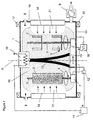
- FIG. 1 shows a schematic cross section through the process chamber 1 of an inventive Coating plant.
- the parts to be coated 2 are on one or more Mounting devices 3 mounted, the means for generating an at least simple 4, If necessary, also includes double 5 rotation of the parts.
- the support devices 3 on an addition to the plant axis 6 rotatable carousel 7 positioned.
- the different process gases, in particular Ar and acetylene, in the process chamber by means of suitable, not shown here control devices be supplied.
- a high vacuum suitable pumping station 9 is flanged to the chamber.
- An ion source 10 is preferably arranged in the region of the system axis, which is connected to the negative output of a DC power supply 11 is connected.
- the positive pole the DC power supply 11 can, depending on the process step via a switch 12 the carousel 7 or to the mounting device 3 and the thus electrically connected Parts 2 (heating process) or to the auxiliary anode 13 (etching process, or if necessary during the coating processes) are created.
- evaporator source 14 On the walls of the process chamber 1 is at least one evaporator source 14, preferably a magnetron or an arc evaporator for applying the adhesion and gradient layer intended.
- evaporator source not shown here 14 this can be used as anodized crucible centrally in the bottom of the process chamber 1 attached.
- the vaporization material is used for producing the transitional or gradient layer by heating through the low-voltage arc 15 in the gas phase converted.
- an additional electrical power supply 16 is provided, with their help to the substrates a periodically varying medium frequency voltage in the range between 1-10,000, preferably between 20 and 250 kHz can be applied.
- the electromagnetic coils 17 for generating a longitudinal, the plasma space penetrating magnetic field are on opposite boundary walls of the process chamber 1 and are separated by at least one, preferably two separate, fed here not shown DC voltage sources in the same direction.
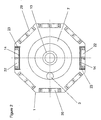
- magnetic systems 20 for forming a plurality of magnetic near fields 21 attached become.
- magnetic systems 20 for forming a plurality of magnetic near fields 21 attached including at least a magnetron magnet system 22, such as shown in FIG. 2, alternately Magnetic systems arranged with NSN or SNS polarity and thus a magnetic tunnel-shaped, looped enclosure of the plasma in the process chamber causes.
- the magnetic systems 20 are formed for near field generation as magnetron magnet systems.
- the individual systems of the coating system are advantageously set in relation to each other by a process control. This makes it possible, in addition to the basic functions of a Vakummbe Anlagenllungsstrom (pump control, safety control loops, etc.), the various plasma-generating systems such as magnetrons with the magnetron supply, ionization chamber 1 and auxiliary anode 13 or carousel 7 and DC power supply 11, and carousel 7 and Medium frequency generator 16, as well as the corresponding adjustment of the gas flows, as well as the control of the optionally different coil currents in a flexible manner to adapt to each other and to optimize for different processes.
- the various plasma-generating systems such as magnetrons with the magnetron supply, ionization chamber 1 and auxiliary anode 13 or carousel 7 and DC power supply 11, and carousel 7 and Medium frequency generator 16, as well as the corresponding adjustment of the gas flows, as well as the control of the optionally different coil currents in a flexible
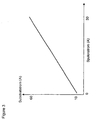
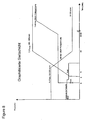
- Figure 3 shows the relationship between substrate current and coil current in use Helmholtz coils to build a magnetic field. It turns out that the substrate current, and thus the plasma intensity directly proportional to the coil current and thus are for magnetic field structure. This clearly shows the positive effect of a superimposed one Magnetic field.
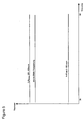
- FIG. 4 shows the course of individual parameters during the application of a Gradient layer shown:
- the substrate bias will be from DC to center frequency with a preferred one Amplitude voltage between 500 and 2500 V and a frequency between 20 and 250 kHz, switched.
- an acetylene ramp is started at 50 sccm and drove over about 30 minutes to 350 sccm.
- the power of the Cr targets used is 7 kW, after another 10 Minutes back to 5 kW, and held there for another 2 minutes constant.
- Apertures are driven in front of the targets and these shut off, bringing the deposition consisting essentially of carbon, small amounts of hydrogen and even lower Quantities of argon atoms built up "pure" DLC layer begins.
- FIGS. 4 and 5 the course of individual parameters during application is shown by way of example of the pure DLC layer: After switching off the Cr targets used is at constant adjusted medium frequency supply and constant flow of argon the acetylene ramp started during the gradient layer about 10 minutes uniformly increased to a flow between about 200-400 sccm. Subsequently The argon flow is continuously applied to a flow between 5 minutes over a period of 5 minutes about 0 - 100 sccm withdrawn. The next 55 minutes will be added to the process consistent settings completed.
- FIG. 6 shows a scanning electron micrograph of a fracture surface of an inventive device DLC layer system. It can be clearly seen that in the area of the cover layer diamond-like carbon is a fine-grained structure, so that the DLC layer has a polycrystalline character.
- FIG. 7 shows, by way of example, the overall course of individual process parameters during the process Applying an inventive DLC layer system.
- FIG. 8 shows, by way of example, the overall course of individual process parameters during the application of an inventive DLC sliding layer system with a graphitized sliding layer.
- the pulsed Substratbias set by means of a voltage ramp to a value between 1500 and 2500 V and then deposited an inlet layer under constant conditions.
- FIG. 9 shows an example of the overall course of individual process parameters during the application of an inventive DLC sliding layer system with an inverse gradient layer.
- the acetylene ramp is started, for example, at 350 sccm and driven for about 30 minutes to 50 sccm.
- the process is preferably continued while maintaining the settings until a desired layer thickness of the inlet layer is reached.
- FIG. 10 shows an example of the course of individual process parameters during the application of a gradient layer as a sliding layer. This can be similar to the transition layer, but also without a metallic adhesive layer, executed.
- FIG. 11 shows, by way of example, the overall course of individual process parameters during the application of an inventive DLC sliding layer system with an H 2 -rich sliding layer.
- a methane ramp is started and, for example, driven from 0 to 100 sccm over about 30 minutes.
- an acetylene ramp is started at 350 sccm and shut down to 120 sccm for about 30 minutes.
- the run-in layer is run as a layer finish with constant parameters.
- the process chamber is pumped down to a pressure of about 10-5 mbar and the process sequence is started.
- a heating process is carried out to bring the substrates to be coated to a higher temperature and to remove volatile substances from the surface.
- an Ar-hydrogen plasma is ignited by means of the low-voltage arc between the ionization chamber and an auxiliary anode.
- Table 1 shows the process parameters of the heating process: Ar flow 75 sccm Substrate Bias Voltage [V] 0 Electricity of low voltage arc 100 A Hydrogen flow 170 sccm Current upper coil Threshold between 20 and 10 A Current lower coil At the same threshold between 20 and 5 A Period between max. and min. coil current 1.5 min heating 20 min
- the Helmholtz coils are used to activate the plasma and become cyclical driven.
- the current of the upper coil is thereby with a period of 1.5 min varies between 20 and 10 A, the current of the lower coil changes in the same clock counterparts between 5 and 20 A.
- the substrates and the annoying adhering to the surfaces heat up Volatile substances are driven into the gas atmosphere, where they are pumped by the vacuum be sucked off.
- an etching process is started by drawing the ions from the low-voltage arc onto the substrates by means of a negative bias voltage of 150V.
- the alignment of the low-voltage arc and the intensity of the plasma are supported by the pair of Helmholtz coils mounted in a horizontal orientation.
- the following table shows the parameters of the etching process.
- the application of the Cr adhesion layer is begun by the Cr magnetron sputtering targets to be activated.
- the Ar gas flow is set at 115 sccm.
- the Cr sputtering targets are driven with a power of 8 kW and become the substrates now rotates past the targets for a time of 6 minutes.
- the self-adjusting pressure range then lies between 10-3 mbar and 10-4 mbar.
- the sputtering process is through the connection of the low-voltage arc and applying a negative DC bias voltage of 75 V supported on the substrate.
- the low voltage arc is turned off and the deposition is active for the remainder of the Cr sputtering time only with the help of the Cr target Plasmas made.
- a plasma is ignited by switching on a sine wave generator.
- Acetylene gas is introduced at an initial pressure of 50 sccm and the flow is increased by 10 sccm every minute.
- the sine plasma generator is set at a frequency of 40 kHz to an amplitude voltage of 2400 V.
- the generator ignites a plasma discharge between the substrate holders and the housing wall.
- the Helmholtz coils attached to the recipient are both activated with a constant current flow of 3 A in the lower coil and 10 A in the upper coil.
- the Cr targets are deactivated.
- the table shows the parameters of the example at a glance: River Argon 50 sccm Flow acetylene 350 sccm Excitation current upper coil 10 A Excitation current lower coil 3 A voltage amplitude 2400 V Excitation frequency f 40 kHz
- the deposition rate is now in the Coating process will range between 0.5 and 4 ⁇ m / h, which also depends on the area to be coated in the process chamber.
- the sine generator and the gas flow are switched off, and the substrates are taken from the process chamber.
- Example 2 provides a procedure similar to Example 1. Unlike example 1, the plasma is generated by a pulse generator.
- the excitation frequency is included 50 kHz with an amplitude voltage of 700V.
- the table shows the parameters of the second example.
- River Argon 50 sccm Flow acetylene 350 sccm Excitation current upper coil 10 A Excitation current lower coil 3 A voltage amplitude 700V Excitation frequency f 40 kHz
- the coating produced has a hardness of 25 GPa, an adhesive strength of HF1 and gives a coefficient of friction of 0.2.
- Properties Example 2 HK about 2400 deposition rate about 1.5 ⁇ m / h liability HF1 resistance > 500k Hydrogen content 13% Coefficient of friction 0.2 Internal tension Approximately 3 GPa
- Example 3 provides a procedure similar to Example 1. In contrast to Example 1, the plasma is excited by a unipolar pulse voltage, the parameters of the experiment are shown in the following table. River Argon 50 sccm Flow acetylene 350 sccm Excitation current upper coil 10 A Excitation current lower coil 3 A voltage amplitude 1150V Excitation frequency f 30 kHz
- the coating produced has the properties described in the following table.
- Example 4 In comparison with Process Example 1, in Example 4, a process without assistance of a longitudinal magnetic field was performed. The current flowing through the two coils was reduced to a value of 0 A.
- the table shows the process parameters. River Argon 50 sccm Flow acetylene 350 sccm Excitation current upper coil 0A Excitation current lower coil 0A voltage amplitude 2400 V Excitation frequency f 40 kHz
- the acetylene ramp can also be delayed by 5-10 minutes Switching on the Cr targets are started. Such a procedure is particularly advantageous if DLC and sliding layer in different process chambers or coating plants be applied. It can also be used instead of the sine wave generator DC voltage source for applying the Suabstratbias be used.
- the Graphitanteil can be switched on by simultaneous or delayed Co-sputtering of carbidic example, WC and / or Graphittargets be increased. If you want the most favorable sliding properties of W or Ta or Nb / C layers It is advantageous to use the Cr targets after the formation of an adhesive or Turn off gradient or downgrade the process and only with the corresponding metal or Metallkarbidtargets to complete.
- the properties of the corresponding DLC layers are Table 8 and ceremoniesNr. 5 6 7 liability HF 1 HF 1 HF 1 resistance ⁇ 100 k ⁇ ⁇ 100 kQ ⁇ 100 k ⁇ Coefficient of friction about 0.10 approx. 0.15 approx. 0.12
- Table 9 shows: protestNr. 8th 9 10 liability HF 1 HF 1 HF 1 resistance ⁇ 1 k ⁇ ⁇ 1 k ⁇ ⁇ 100 k ⁇ Hydrogen content ng ng > 30 atom% Coefficient of friction about 0.08 about 0.07 approx. 0.13
Abstract
Description
Die vorliegende Erfindung betrifft ein Schichtsystem nach Patenanspruch 1, ein Verfahren
nach Patenanspruch 10 sowie eine Vorrichtung nach Patenanspruch 28. Bevorzugte
Ausführungen der Erfindung werden in den Unteransprüchen 2 bis 9, 11 bis 27 und 29
bis 39 sowie in der Beschreibung, Beispielen und Zeichnungen offengelegt.
Trotz der herausragenden Eigenschaften von diamantähnlichem Kohlenstoffschichten
(DLC-Schichten), wie hoher Härte und ausgezeichneter Gleiteigenschaften, und einer langjährigen
weltweiten Forschungstätigkeit, konnten bis heute noch keine reinen DLC-Schichten
hergestellt werden, die auch bei grösseren Schichtdicken (> 1 µm) eine für den
industriellen Einsatz in typischen Verschleissschutzanwendungen ausreichende Schichthaftung
zeigen und eine ausreichende Leitfähigkeit aufweisen, um auf die mit vielen produktionstechnischen
Nachteilen behafteten Hochfrequenz (HF)-Verfahren zur Herstellung verzichten
zu können.The present invention relates to a layer system according to claim 1, a method according to
Despite the outstanding properties of diamond-like carbon layers (DLC layers), such as high hardness and excellent sliding properties, and a long-term worldwide research activity, it has not been possible to produce pure DLC layers, which are still suitable for larger layer thicknesses (> 1 μm) show sufficient adhesion to the industrial use in typical wear protection applications and have sufficient conductivity to be able to dispense with the high frequency (HF) process with many production-related disadvantages for the production.
Als typische Verschleissschutzanwendungen seien hier einerseits Anwendungen im Maschinenbaubereich, wie Schutz vor Gleitverschleiss, Pitting, Kaltverschweissung etc., insbesondere auf Bauteilen mit gegeneinander bewegten Flächen, wie beispielsweise Zahnrädern, Pumpen- und Tassenstössel, Kolbenringe, Injektorennadeln, komplette Lagersätze oder deren einzelne Bestandteile u.v.a. genannt, sowie andererseits Anwendungen im Bereich der Materialbearbeitung zum Schutz der eingesetzten Werkzeuge zur spanenden oder umformenden Bearbeitung sowie bei Spritzgussformen.Typical wear protection applications include applications in the mechanical engineering sector, such as protection against sliding wear, pitting, cold welding, etc., in particular on components with mutually moving surfaces, such as gears, Pump and bucket tappets, piston rings, injector needles, complete bearing sets or their individual components u.v.a. called, as well as applications in the field of Material processing to protect the tools used for cutting or forming Machining and injection molds.
Neben der vielseitigen Anwendungsmöglichkeiten im Verschleissschutzbereich sei hier noch ausdrücklich der Korrosionsschutz als weiterer vielversprechender Anwendungsbereich von derartigen DLC-Schichten genannt.In addition to the versatile applications in the wear protection area, here still expressly the corrosion protection as another promising application called by such DLC layers.
Reine DLC-Schichten können heute auf Grund der hohen Eigenspannungen und der damit verbundenen problematischen Haftung, insbesondere bei hochbeanspruchten Flächen im Verschleissschutz nur mit geringen, für viele Anwendungen unzureichenden Schichtdicken abgeschieden werden oder müssen durch zusätzlichen Einbau von Fremdatomen, wie beispielsweise Silizium, verschiedenen Metallen und Fluor in ihren Eigenschaften verändert werden. Allerdings war die damit erreichte Verringerung der Schichteigenspannungen und Verbesserung der Haftung immer mit einem deutlichem Härteverlust verbunden, der sich gerade im Verschleissschutzbereich oftmals negativ auf die Lebensdauer des jeweils beschichteten Gegenstands auswirken kann.Pure DLC coatings can today due to the high residual stresses and thus associated problematic adhesion, especially in highly stressed areas in the Wear protection only with low, for many applications insufficient layer thicknesses be deposited or need by additional incorporation of foreign atoms, such as Silicon, various metals and fluorine in their properties changed become. However, the reduction in the stratigraphic stresses and thus achieved was Improvement of liability always associated with a significant loss of hardness, which is Especially in the wear protection area often negative on the life of each coated Object.
Ein zusätzliches Aufbringen von Einlaufschichten, die beispielsweise graphitischen Kohlenstoff und/oder eine Mischung aus Metall bzw. Metallkarbid und Kohlenstoff enthalten, konnte daher nicht in Betracht gezogen werden, da einerseits durch die zum Erreichen des Einlaufeffekts notwendige Mindestschichtdicke weitere schädliche Schichteigenspannungen aufgebaut wurden und andererseits die Haftung auf reinen Kohlenstoffschichten problematisch war. Erst solche Schichten können aber durch die Kombination der sehr harten Kohlenstoffschicht, bzw. Diamantschicht mit der darauf abgeschiedenen Gleit- bzw. Einlaufschicht den zunehmenden Anforderungen für Bauteile, wie sie beispielsweise für einzelne Komponenten im modernen Motorenbau gefordert werden entsprechen.An additional application of inlet layers, for example, graphitic carbon and / or a mixture of metal or metal carbide and carbon, could therefore not be taken into account, on the one hand by the Enema effect necessary minimum layer thickness more harmful Strengths were built on the one hand and on the other hand, the liability to clean Carbon layers was problematic. Only such layers can but through the Combination of the very hard carbon layer or diamond layer with it deposited sliding or inlet layer the increasing requirements for components, as required, for example, for individual components in modern engine construction will match.
Bei heute üblichen plasmagestützten Verfahren zur Herstellung von DLC-Schichten werden auf Grund des hohen elektrischen Widerstandes harter DLC-Schichten häufig, um störende Aufladungen während der Beschichtung zu vermeiden, Prozesse mit einem HF-Bias bzw. Plasma (als HF = Hochfrequenz werden im folgenden alle Frequenzen > 10 MHz verstanden), insbesondere mit der Industriefrequenz 13,56 MHz, angewandt. Die bekannten Nachteile dieser Technik, sind schwer beherrschbare Störungen elektronisch empfindlicher Prozesssteuerungseinheiten (HF-Rückkopplungen, Senderwirkung, ...) ein erhöhter Aufwand um HF-Ueberschläge zu vermeiden, Antennenwirkung der zu beschichtenden Substrate und ein damit verbundener relativ grosser Mindestabstand zwischen dem Beschichtungsgut, der eine optimale Raum- und Flächennutzung in der Beschichtungskammer verhindert. So ist bei HF-Verfahren genauestens darauf zu achten, dass es, beispielsweise durch eine zu hohe Beladungsdichte, falsche Substrat / Halterungsabstände etc., nicht zu einer Überlappung von Dunkelräumen kommt, wodurch schädliche Nebenplasmen entstehen. Derartige Nebenplasmen bilden einerseits Energiesenken und belasten so zusätzlich die Plasmageneratoren, andererseits kommt es durch derartige lokale Plasmakonzentrationen häufig zu einer thermischen Überhitzung der Substrate und unerwünschter Graphitisierung der Schicht.In today's conventional plasma-assisted processes for the production of DLC layers due to the high electrical resistance of hard DLC layers, often to disturbing Charging during coating to avoid processes with an RF bias or Plasma (as HF = high frequency are understood in the following all frequencies> 10 MHz), especially with the industrial frequency 13.56 MHz applied. The well-known Disadvantages of this technique, are difficult to control disturbances electronically sensitive Process control units (RF feedback, transmitter effect, ...) increased effort in order to avoid HF-overtopping, antenna effect of the substrates to be coated and an associated relatively large minimum distance between the coating material, which prevents optimal space and land use in the coating chamber. For example, care must be taken with HF procedures to ensure that, for example, through Too high loading density, wrong substrate / support distances, etc., not one Overlapping of dark rooms is the result, causing harmful secondary plasmas. On the one hand, such secondary plasmas create energy sinks and thus additionally burden the Plasma generators, on the other hand, it comes through such local plasma concentrations often to thermal overheating of the substrates and unwanted graphitization the layer.
Auf Grund der bei HF-Prozessen berechneten exponentiellen Abhängigkeit der Substratspannung
von der Substratoberfläche
Ferner ist auf der Anlagenseite bei HF-Prozessen üblicherweise zusätzlicher apparativer
Aufwand notwendig, um Generator- und Plasmaimpedanzen durch elektrische Netzwerke,
wie beispielsweise eine sogenannte Matchbox, während des Prozesses dynamisch aneinander
anzupassen.
Im folgenden werden kurz verschiedene aus dem Stand der Technik bekannte Verfahren
bzw. Schichtsysteme angeführt. Furthermore, on the plant side in HF processes usually additional expenditure on equipment is necessary to dynamically adapt generator and plasma impedances by electrical networks, such as a so-called matchbox, during the process.
In the following, various known from the prior art method or layer systems are briefly mentioned.
Die EP 87 836 offenbart ein DLC-Schichtsystem mit einem 0,1 - 49,1%igen Anteil metallischer Komponenten, welches beispielsweise mittels kathodischem Sputtern abgeschieden wird.EP 87 836 discloses a DLC layer system with a 0.1-49.1% proportion of metallic Components, for example, deposited by means of cathodic sputtering becomes.
Die DE 43 43.354 A1 beschreibt ein Verfahren zur Herstellung eines mehrlagigen Tihaltigen Schichtsystems mit einer Hartstoffschicht aus Titannitriden Titankarbiden und Titanboriden sowie einer reibmindernden C-haltigen Oberflächenschicht, wobei der Ti- und N-Anteil in Richtung der Oberfläche fortschreitend verringert wird.DE 43 43 354 A1 describes a method for producing a multi-layer Tihaltigen Layer system with a hard material layer of titanium nitrides titanium carbides and titanium borides and a Reibmindernden C-containing surface layer, wherein the Ti and N content in the direction of the surface is progressively reduced.
Einen gepulsten Plasmastrahl verwendet das in der US 5 078 848 beschriebene Verfahren zur Herstellung von DLC-Schichten. Auf Grund der gerichteten Teilchenstrahlung aus einer Quelle mit geringem Austrittsquerschnitt eignen sich aber solche Verfahren nur bedingt zur gleichmässigen Beschichtung grösserer Flächen.A pulsed plasma jet uses the method described in US 5,078,848 for the production of DLC layers. Due to the directed particle radiation from a Source with a small outlet cross-section, but such methods are only conditionally to uniform coating of larger surfaces.
Verschiedene CVD-Verfahren bzw. mit solchen Verfahren hergestellte SiDLC/DLC Mischschichten werden in den folgenden Dokumenten beschrieben:Various CVD processes or SiDLC / DLC mixed layers produced by such processes are described in the following documents:
Die EP-A-651 069 beschreibt ein reibminderndes Verschleissschutzsystem aus 2 - 5000 alternierenden DLC und SiDLC-Schichten. Ein Verfahren zur Abscheidung von a-DLC-Schichten mit einer Si-Zwischenschicht und daran anschliessender a-SiC:H-Uebergangszone zur Verbesserung der Haftung wird in der EP-A-600 533 beschrieben. Auch in der EP-A-885 983 und der EP-A-856 592 werden verschiedene Verfahren zur Herstellung solcher Schichten beschrieben. In der EP-A-885 983 beispielsweise wird das Plasma durch ein DC-beheiztes Filament erzeugt und die Substrate mit negativer Gleichspannung oder MF zwischen 20 - 10.000 kHz beaufschlagt (als MF = Mittelfrequenz wird im folgenden der Frequenzbereich zwischen 1 und 10.000 kHz verstanden).EP-A-651 069 describes a friction-reducing wear protection system from 2 to 5000 alternating DLC and SiDLC layers. A method for the deposition of a-DLC layers with an Si intermediate layer and subsequent a-SiC: H transition zone for improving the adhesion is described in EP-A-600 533. Also in EP-A-885 983 and EP-A-856 592 are various methods of preparation such layers described. In EP-A-885 983, for example, the plasma generated by a DC heated filament and the substrates with negative DC voltage or MF between 20 - 10,000 kHz (as MF = center frequency is in following understood the frequency range between 1 and 10,000 kHz).
Die US 4 728 529 beschreibt eine Methode zur Abscheidung von DLC unter Anwendung eines HF-Plasmas, bei der die Schichtbildung in einem Druckbereich zwischen 103 und 1 mbar aus einem sauerstofffreien Kohlenwasserstoffplasma, dem bei Bedarf Edelgas oder Wasserstoff beigemischt wird, erfolgt.US 4,728,529 describes a method for the deposition of DLC using an HF plasma in which the layer formation in a pressure range between 103 and 1 mbar from an oxygen-free hydrocarbon plasma, the noble gas or Hydrogen is added takes place.
Der in der DE-C-195 13 614 beschriebene Prozess verwendet eine bipolare Substratspannung mit einer kürzeren positiven Pulsdauer in einem Druckbereich zwischen 50-1000 Pa. Damit werden Schichten im Bereich von 10 nm bis 10 µm und einer Härte zwischen 15 - 40 GPa abgeschieden.The process described in DE-C-195 13 614 uses a bipolar substrate voltage with a shorter positive pulse duration in a pressure range between 50-1000 Pa. Thus, layers in the range of 10 nm to 10 microns and a hardness between 15 - 40 GPa deposited.
Ein CVD-Verfahren mit unabhängig vom Beschichtungsplasma erzeugter Substratspannung wird in der DE-A-198 26 259 beschrieben, wobei bevorzugt bipolare, jedoch auch andere periodische veränderte Substratspannungen angelegt werden. Dies bedarf jedoch einer relativ aurwendigen, da in zweifacher Ausführung vorzusehenden, elektrischen Versorgungseinheit zur Durchführung des Verfahrens.A CVD method with substrate voltage generated independently of the coating plasma is described in DE-A-198 26 259, preferably bipolar, but also other Periodic changes in substrate voltages are applied. However, this requires a relative aurwendigen, as to be provided in duplicate, electrical supply unit to carry out the process.
Weiters sind Verfahren aus einer Kombination traditioneller Hartstoffschichten mit einer
kohlenstoffreichen Deckschicht mit günstigen Gleiteigenschaften schon länger bekannt.
Beispielsweise offenbart US 5,707,748 eine Schichtkombinationen aus metallhaltigen
Hartstoffschichten (TiN, TiAIVN, WC) und einer weniger harten Metallkarbidschicht mit
zunehmendem Gehalt an graphitisch, d.h. in sp2 Hybridisierung, gebundenem Kohlenstoff.
Durch die guten Gleiteigenschaften von Metall/- bzw. Metallkarbid/Kohlenstoffschichten
(MeC/C) werden diese bevorzugt in Tribosystemen eingesetzt, wo neben dem Schutz des
beschichteten Teils eine Verringerung der Reibungskräfte und/oder ein Schutz des
Gegenkörpers bewirkt werden sollen. Besonders wirkungsvoll haben sich diesbezüglich
MeC/C-Schichten mit einem hohen C-Anteil erwiese, bei denen durch die weiche
Deckschicht einerseits ein Einlaufeffekt, andererseits durch Übertrag von C-Partikeln ein
Schmiereffekt für das ganze Tribosystem erreicht werden kann. Ähnliche
Schichtkombinationen mit einer die Haftung verbessernden metallischen Zwischenschicht
zwischen der Hartstoffschicht und der graphitischen Kohlenstoff enthaltenden Metall- bzw.
MeC-Schicht werden in WO 99-55929 beschrieben. Furthermore, processes from a combination of traditional hard material layers with a carbon-rich cover layer with favorable sliding properties have been known for some time.
For example, US Pat. No. 5,707,748 discloses a layer combination of metal-containing hard material layers (TiN, TiAIVN, WC) and a less hard metal carbide layer with increasing content of carbon bonded graphitically, ie in sp 2 hybridization. Due to the good sliding properties of metal / - or metal carbide / carbon layers (MeC / C), these are preferably used in tribosystems, where in addition to the protection of the coated part, a reduction of the frictional forces and / or protection of the counter body to be effected. In this regard, MeC / C layers with a high C content have proven to be particularly effective, in which the soft cover layer on the one hand achieves an enema effect, and on the other hand, by transferring C particles, a lubricating effect for the entire tribosystem. Similar layer combinations with a adhesion enhancing metallic intermediate layer between the hard material layer and the graphitic carbon-containing metal or MeC layer are described in WO 99-55929.
Der Artikel "DLC multilayer coatings for wear protection" von Deng J. et al., Diamond and Related Materials, Elsevier Science Publishers, Amsterdam, NL, Bd. 4, Nr. 7, 15. Mai 1995, S. 936- 943 offenbart eine DLC Multilayer- Beschichtung als Verschleißschutz. Die DLC-Schicht ist auf einer Ti- Haftschicht und einer Multilayer- Übergangsschicht aus einer Abfolge von TiN, TiCN und TiC aufgebracht. Die Übergangsschicht ist eine vielschichtige Gradientenschicht, in der der Stickstoffgehalt abnimmt und der Kohlenstoffgehalt zur DLC-Schicht hin zunimmt.The article "DLC multilayer coatings for wear protection" by Deng J. et al., Diamond and Related Materials, Elsevier Science Publishers, Amsterdam, NL, vol. 4, no. 7, 15 May 1995, Pp. 936-943 discloses a DLC multilayer coating for wear protection. The DLC layer is on a Ti adhesive layer and a multilayer transition layer of a sequence of TiN, TiCN and TiC applied. The transitional layer is a complex one Gradient layer in which the nitrogen content decreases and the carbon content to the DLC layer increases.
Die Druckschrift FR 2 596 775 zeigt einen Prozess zur Herstellung eines Schichtsystems sowie das Schichtsystem selbst. Die spezielle Anlagengeometrie zielt auf eine möglichst hohe Ionisation des Prozessgases bzw. des Metalldampfes ab. Eine dritte Elektrode ist vorgesehen, um ein Abdriften von Elektronen an die Wände zu verhindern. Eine Elektronenkanone ist im unteren Bereich des Gehäuses angeordnet.The document FR 2 596 775 shows a process for producing a layer system as well as the coating system itself. The special plant geometry aims at a possible high ionization of the process gas or metal vapor. A third electrode is provided to prevent drifting of electrons to the walls. An electron gun is located in the lower part of the housing.
Die US 5,709,784 betrifft eine Vorrichtung zum Beschichten mittels einer Niedervolt- Bogenentladung. Die Vorrichtung umfasst, neben den üblichen Komponenten, insbesondere auch eine Einrichtung zum Anlegen einer Substratbiasspannung an das Substrat, sowie Helmholtz- Spulen zur Erzeugung eines Magnetfelds. Mittels dieser Anlage kann ein Niedervoltbogenprozess durchgeführt werden. Neben einer Kathode und einer Anode ist eine zusätzliche Spannungsquelle zur Erzeugung einer positiven Gleichspannung an der Anode vorgesehen. US 5,709,784 relates to a device for coating by means of a low-voltage arc discharge. The device comprises, in addition to the usual components, in particular also a device for applying a Substratbiasspannung to the substrate, as well Helmholtz coils for generating a magnetic field. By means of this system can a low-voltage arc process be performed. Next to a cathode and an anode is one additional voltage source for generating a positive DC voltage at the anode intended.
Entsprechend ist es die Aufgabe der vorliegenden Erfindung relativ dicke DLC-Schichtsysteme mit hoher Härte und ausgezeichneter Haftfestigkeit zur Verfügung zu stellen, die ausserdem noch eine genügend hohe Leitfähigkeit besitzen, um ohne HF-Bias abgeschieden werden zu können, so dass ein Verfahren und eine Vorrichtung verwendet werden können, die keinen grossen Aufwand erfordern und eine hohe Effektivität für den industriellen Einsatz aufweisen. Entsprechend ist es auch eine Aufgabe der vorliegenden Erfindung ein entsprechendes Verfahren und eine Vorrichtung bereitzustellen.Accordingly, the object of the present invention is relatively thick DLC layer systems to provide with high hardness and excellent adhesion, which also have a sufficiently high conductivity to be deposited without RF bias so that a method and apparatus can be used can, which require little effort and high efficiency for the industrial Use have. Accordingly, it is also an object of the present invention to provide a corresponding method and an apparatus.
Diese Aufgabe wird gelöst durch die Schicht mit den Merkmalen des Anspruchs 1
sowie dem Verfahren nach Anspruch 10 und der Vorrichtung gemäss Anspruch 28.
Vorteilhafte Ausgestaltungen sind Gegenstand der Unteransprüche.This object is achieved by the layer having the features of claim 1
and the method according to
Überraschenderweise hat sich weiters gezeigt, dass es möglich ist, auch relativ dicke DLC-Schichten
mit einer zusätzlichen Schicht mit besonders günstigen Gleit- und falls
erwünscht Einlaufeigenschaften zu versehen, ohne dass dadurch die Haftfestigkeit
verschlechtert wird. Dadurch gelingt es erstmals die grosse Härte von reinen DLC-Schichten
mit den günstigen Gleiteigenschaften von Metallkohlenstoffschichten zu
kombinieren. Dies kann nicht nur durch Aufbringen von Gleitschichten auf erfinderische
DLC-Schichtsysteme, sondern auch durch Anwendung eines der beschriebenen Verfahren
zur Aufbringung einer Gleitschicht auf bekannte DLC-Schichten bzw. DLC-Schichtsysteme
erfolgen.
Aufgabe der vorliegenden Erfindung ist es somit insbesonders auch eine DLC- bzw. eine
Diamantschicht mit einer ausgezeichneter Haftfestigkeit und einem hohen Verschleisswiderstand
zur Verfügung zu stellen, die gegenüber herkömmlichen DLC- bzw. Diamantschichten
verbesserte Gleiteigenschaften und falls erwünscht Einlaufeigenschaften aufweist.
Eine solche DLC-Gleitschichtsystem kann für den Verschleissschutz, den Korrosionsschutz
und zur Verbesserung der Gleiteigenschaften von Vorteil sein, insbesonders dann, wenn bis
jetzt schwer in einem Schichtsystem zu verwirklichende Eigenschaften gleichzeitig
erwünscht sind.
Eine weitere Aufgabe der Erfindung ist es ein Verfahren und eine Vorrichtung zur
Herstellung eines erfindungemässen DLC-Gleitschichtsystems zu Verfügung zu stellen. Surprisingly, it has further been found that it is possible to provide even relatively thick DLC layers with an additional layer with particularly favorable sliding and, if desired, shrinkage properties without thereby impairing the adhesive strength. This makes it possible for the first time to combine the high hardness of pure DLC layers with the favorable sliding properties of metal carbon layers. This can be done not only by applying lubricating layers to inventive DLC layer systems, but also by using one of the described methods for applying a sliding layer on known DLC layers or DLC layer systems.
It is therefore an object of the present invention in particular also to provide a DLC or a diamond layer having an excellent adhesive strength and a high wear resistance, which has improved sliding properties and, if desired, running-in properties compared with conventional DLC or diamond layers. Such a DLC overlay system may be advantageous for wear protection, corrosion protection, and slip resistance, especially when properties which are difficult to realize in a sheeting system are desired at the same time.
A further object of the invention is to provide a method and a device for producing a DLC sliding layer system according to the invention.
Dies wird gemäß den unabhängigen Ansprüchen gelöst.This is solved according to the independent claims.
Ein erfindungsgemässes DLC-Schichtsystem wird durch Herstellen einer Schicht mit folgendem Schichtaufbau erreicht.A DLC layer system according to the invention is achieved by producing a layer with the following layer structure.
Direkt auf dem Substrat befindet sich eine Haftschicht mit mindestens einem Element aus der Gruppe der Elemente der IV, V und VI Nebengruppe sowie Si. Bevorzugt wird eine Haftschicht aus den Elementen Cr oder Ti verwendet, die sich für diesen Zweck als besonders geeignet erwiesen haben.Directly on the substrate there is an adhesive layer with at least one element the group of elements of IV, V and VI subgroup as well as Si. Preferred is a Adhesive layer of the elements Cr or Ti used, which is particularly suitable for this purpose have proved suitable.
Daran schliesst sich eine Uebergansschicht an, die vorzugsweise als Gradientenschicht ausgebildet ist, in deren Verlauf senkrecht zur Substratoberfläche der Metallgehalt ab - und der C-Gehalt zunimmt.This is followed by a transition layer, which is preferably formed as a gradient layer is, in the course perpendicular to the substrate surface of the metal content - and the C content increases.
Die Uebergangsschicht umfasst im wesentlichen Kohlenstoff und mindestens ein Element aus der Gruppe der Elemente, die die Haftschicht bilden. Zusätzlich kann bei einer bevorzugten Ausführungsform Wasserstoff enthalten sein. Darüber hinaus beinhalten sowohl die Uebergangsschicht als auch die Haftschicht unvermeidbare Verunreinigungen, wie sie beispielsweise durch in die Schicht eingebaute Atome aus der umgebenden Atmosphäre gegeben sind, beispielsweise die bei der Herstellung verwendeten Edelgase, wie Argon oder Xenon.The transition layer essentially comprises carbon and at least one element from the group of elements forming the adhesive layer. Additionally, in a preferred Embodiment be contained hydrogen. In addition, both include Transition layer as well as the adhesive layer unavoidable impurities, as for example given by atoms incorporated into the layer from the surrounding atmosphere are, for example, the noble gases used in the production, such as argon or xenon.
Bei der Ausbildung der Uebergangsschicht in Form einer Gradientenschicht kann der Zuwachs des Kohlenstoffs in Richtung der Deckschicht durch Zunahme gegebenenfalls unterschiedlicher karbidischer Phasen, durch Zunahme des freien Kohlenstoffs, bzw. durch eine Mischung derartiger Phasen mit der metallischen Phase der Uebergangsschicht erfolgen. Die Dicke der Gradienten- bzw. Uebergangsschicht kann dabei, wie dem Fachmann bekannt, durch Einstellung geeigneter Prozessrampen eingestellt werden. Die Zunahme des C-Gehalt bzw. Abnahme der metallischen Phase kann kontinuierlich oder stufenweise erfolgen, ferner kann zumindest in einem Teil der Uebergangsschicht auch eine Abfolge metallreicher und C-reicher Einzelschichten zum weiteren Abbau von Schichtspannungen vorgesehen werden. Durch die erwähnten Ausbildungen der Gradientenschicht werden die Materialeigenschaften (beispielsweise E-Modul, Struktur etc.) der Haft- und der abschliessenden DLC-Schicht im wesentlichen kontinuierlich aneinander angepasst und damit der Gefahr der Rissbildung entlang einer sonst auftretenden Metall bzw. Si /DLC-Grenzfläche entgegengewirkt.In the formation of the transition layer in the form of a gradient layer, the increase of the carbon towards the topcoat by increasing, if necessary, different carbide phases, by increasing the free carbon, or by a Mixture of such phases with the metallic phase of the transition layer take place. The thickness of the gradient or transition layer can, as known in the art, be set by setting suitable process ramps. The increase in C content or decrease of the metallic phase can take place continuously or stepwise, Furthermore, at least in a part of the transition layer, a sequence of metal rich and C-rich monolayers for further degradation of layer stresses become. Due to the mentioned embodiments of the gradient layer, the material properties (For example, modulus of elasticity, structure, etc.) of the adhesive and the final DLC layer substantially continuously matched to each other and thus the danger the crack formation along an otherwise occurring metal or Si / DLC interface counteracted.
Den Abschluss des Schichtpakets bildet eine im wesentlichen ausschliesslich aus Kohlenstoff und vorzugsweise Wasserstoff bestehende Schicht, mit einer im Vergleich zur Haft- und Uebergansschicht grösseren Schichtdicke. Zusätzlich zum Kohlenstoff und Wasserstoff können auch hier Edelgase, wie Argon oder Xenon vorkommen. Wesentlich ist hier jedoch, dass auf zusätzliche metallische Elemente oder Silizium vollständig verzichtet wird.The conclusion of the layer package forms a substantially exclusively of carbon and preferably hydrogen-containing layer, with one compared to the adhesive and transition layer greater layer thickness. In addition to carbon and hydrogen can also occur here noble gases, such as argon or xenon. However, it is essential here that is completely dispensed with additional metallic elements or silicon.
Die Härte des gesamten DLC-Schichtsystems ist auf einen Wert grösser 15 GPa, bevorzugt
grösser/gleich 20 GPa eingestellt und eine Haftfestigkeit besser oder gleich HF 3, bevorzugt
besser oder gleich HF 2, insbesondere gleich HF 1 nach VDI 3824 Blatt 4 wird erreicht. Die
Härte wird hierbei über die Knoop Härtemessung mit o,1 N Last, d.h. HK0,1 entsprechen.
Der Oberflächenwiderstand der DLC-Schicht liegt zwischen δ = 10-6Ω und δ = 5MΩ, bevorzugt
zwischen 1Ω und 500 kΩ, bei einem Elektrodenabstand von 20 mm. Gleichzeitig
zeichnet sich die vorliegende DLC-Schicht durch die für DLC typische niedrige Reibkoeffizienten,
bevorzugt µ ≤ 0.3 im Stift / Scheibetest, aus.The hardness of the entire DLC layer system is to a value greater than 15 GPa, preferred
greater than or equal to 20 GPa and an adhesive strength better than or equal to
Die Schichtdicken sind insgesamt > 1 µm, vorzugsweise > 2 µm, wobei die Haftschicht und die Uebergangsschicht vorzugsweise Schichtdicken von 0.05 µm bis 1,5 µm, insbesondere von 0,1 µm bis 0,8 µm aufweisen, während die Deckschicht vorzugsweise eine Dicke von 0,5 µm bis 20 µm, insbesondere 1 µm bis 10 µm hat. The layer thicknesses are in total> 1 .mu.m, preferably> 2 .mu.m, wherein the adhesive layer and the transition layer preferably layer thicknesses of 0.05 .mu.m to 1.5 .mu.m, in particular from 0.1 microns to 0.8 microns, while the top layer preferably has a thickness of 0.5 μm to 20 μm, in particular 1 μm to 10 μm.
Der H-Gehalt ist in der Deckschicht vorzugsweise 5 bis 30 Atom%, insbesondere 10 - 20 Atom%.The H content in the outer layer is preferably 5 to 30 atom%, especially 10 to 20 Atom%.
In REM-Aufnahmen zeigen erfindungsgemässe abgeschiedene DLC-Schichtsysteme Bruchfläche, die im Gegensatz zu herkömmlichen DLC-Schichten, keine glasig-amorphe sondern eine feinkörnige Struktur aufweisen, wobei die Korngrösse bevorzugt ≤ 300 nm, insbesondere ≤ 100 nm beträgt.In SEM images, deposited DLC layer systems according to the invention show fracture surface, unlike conventional DLC layers, not glassy-amorphous but have a fine-grained structure, wherein the grain size preferably ≤ 300 nm, in particular ≤ 100 nm.
In tribologischen Tests unter hoher Belastung zeigt die Beschichtung eine vielfache Lebensdauer gegenüber anderen DLC-Schichten, wie beispielsweise Metallkohlenstoff-, insbesonders WC/C-Schichten. So konnte auf einer mit einer DLC-Schicht versehenen Einspritzdüse für Verbrennungsmotoren im Test nach 1000h nur ein geringfügiger Verschleiss festgestellt werden, wohingegen im selben Test eine mit WC/C beschichtete Düse bereits nach 10h auf Grund eines hohen Oberflächenverschleisses bis in den Grundwerkstoff ausfiel.In tribological tests under high load, the coating shows a multiple lifetime over other DLC layers, such as metal carbon, in particular WC / C layers. So could on a provided with a DLC-layer injector For internal combustion engines in the test after 1000h only a slight wear found whereas, in the same test, a WC / C coated nozzle already appeared after 10 hours Reason for a high surface wear down to the base material precipitated.
Die Schichtrauhigkeit der erfindungsgemässen DLC-Schicht hat vorzugsweise einen Wert von Ra=0.01-0.04; wobei Rz nach DIN gemessen < 0.8 bevorzugt < 0.5 ist.The layer roughness of the DLC layer according to the invention preferably has a value of Ra = 0.01-0.04; where Rz measured to DIN <0.8, preferably <0.5.
Die Vorteile eines erfindungsgemässen DLC-Schichtsystems mit obigen Eigenschaften liegen in der erstmals gelungenen Kombination von grossen Schichtdicken mit ausgezeichneter Haftfestigkeit, die noch eine ausreichende Leitfähigkeit aufweisen, um eine verhältnismässig einfache Prozessführung in der industriellen Produktion zu ermöglichen.The advantages of a novel DLC layer system with the above properties are in the first successful combination of large layer thicknesses with excellent Adhesive strength, which still have sufficient conductivity to a relatively to facilitate simple process control in industrial production.
Trotz der hohen Härte von > 15 GPa, bevorzugt ≥ 20 GPa zeigt die Schicht auf Grund ihrer Struktur und der erfindungsgemässen Verfahrensschritte eine deutlich verbesserte Haftung. Herkömmliche Schichtsysteme benötigen hier eine Dotierung in der Funktionsschicht (DLC), um die Schichtspannung zu reduzieren, was aber auch die Härte reduziert. Despite the high hardness of> 15 GPa, preferably ≥ 20 GPa, the layer shows due to its Structure and the inventive steps a significantly improved adhesion. Conventional layer systems require doping in the functional layer (DLC) to reduce the layer stress, but also reduces the hardness.
Auch REM-Bruchbilder der erfindungsgemässen Schicht zeigen im Gegensatz zu bisher bekannten DLC-Schichten, die die typische Bruchform einer amorphen spröden Schicht mit teils muscheligen Ausbrüchen besitzen, eine feinkörnige gerade Bruchfläche. Schichten mit dem oben beschriebenen Eigenschaftsprofil eignen sich besonders für Anwendungen im Maschinenbau wie zum Beispiel zur Beschichtung von hochbelasteten Pumpen- bzw. Tassenstösseln und Ventiltrieben, Nocken bzw. Nockenwellen wie sie für Kfz-Verbrennungsmotoren und Getriebe verwendet werden, aber auch für den Schutz von hochbelasteten Zahnrädern, Plungern, Pumpenspindeln u.a. Bauteilen bei denen eine besonders harte und glatte Oberfläche mit guten Gleiteigenschaften benötigt wird.REM fractions of the inventive layer show in contrast to previously known DLC layers containing the typical fracture of an amorphous brittle layer have partly mussel-like eruptions, a fine-grained straight fracture surface. Layers with The property profile described above is particularly suitable for applications in the Mechanical engineering, for example for the coating of highly loaded pump or cup tappets and valve trains, cams and camshafts as they are for automotive internal combustion engines and gear are used, but also for the protection of highly loaded Gears, plungers, pump spindles and others. Components in which a special hard and smooth surface with good sliding properties is needed.
Im Werkzeugbereich können dies Schichten auf Grund ihrer hohen Härte und sehr glatten Oberfläche vorteilhaft vor allem für Umform- (Pressen, Stanzen, Tiefziehen, ...) und Spritzgusswerkzeuge, jedoch auch, mit gewissen Einschränkungen bei der Bearbeitung von Eisenwerkstoffen, für Schneidwerkzeuge eingesetzt werden, insbesondere wenn für die Anwendung ein geringer Reibkoeffizient gepaart mit einer hohen Härte notwendig ist.In the tool area, this can be due to their high hardness and very smooth layers Surface advantageous especially for forming (pressing, stamping, deep drawing, ...) and injection molding tools, but also, with certain limitations in the processing of ferrous materials, be used for cutting tools, especially if for the application a low coefficient of friction coupled with a high hardness is necessary.
Die Wachstumsgeschwindigkeit der DLC-Schicht liegt bei etwa 1-3 µm/h, die Schichtspannung
für das ganze System bei 1-4 GPa und somit im üblichen Bereich von harten
DLC-Schichten. Die Leitfähigkeit wird auf Grund der obiger Ausführungen etwa zwischen
δ = 10-6 Ω und δ = 5 MΩ, bevorzugt zwischen δ = 10-3 Ω und δ = 500 kΩ eingestellt
(gemessen wurde hierbei der Oberflächenwiderstand bei einem Abstand der Messelektroden
von 20 mm).
Die mit erfindungsgemäss abgeschiedenen DLC-Schichtsystemen erreichten Gleiteigenschaften
sind zwar günstiger als die anderer beispielsweise nitridischer und/oder karbidischer
Hartstoffschichten, erreichen aber weder die ausserordentlich kleinen Reibkoeffizienten
die sich mit Metall/Kohlenstoffschichten verwirklichen lassen, noch sind sie als
Einlaufschichten geeignet.
Sollen die Gleit- bzw. Einlaufeigenschaften der DLC-Schicht bzw. des DLC-Schichtsystems
weiter verbessert werden, so empfiehlt es sich noch eine abschliessende weichere, einen
relativ grossen Anteil an graphitischen Kohlenstoff enthaltende Gleitschicht aufzubringen.
Letztere kann auch vorteilhaft auf nicht erfinderische DLC-Schichten und -Schichtsysteme
sowie auf Diamanschichten, insbesonders auf nanokirstalline Diamantschichten,
aufgebracht werden.
Im Folgenden wird der Aufbau eines erfindungsgemässen DLC-Gleitschichtsystems
beschrieben, das vorteilhafterweise, jedoch keinesfalls einschränkend, aus einem wie oben
beschriebenen DLC-Schichtsystem mit einer darauf abgelegten Gleitschicht besteht. Überraschenderweise
hat sich gezeigt, dass es mit sehr unterschiedlich aufgebauten Gleitschichten
möglich ist neben der Verbesserung der Gleit- und eventuell Einlaufeigenschaften,
trotz der erhöhten Schichtdicke die ausgezeichnete Haftfestigkeit des DLC-Schichtsystems
für das DLC-Gleitschichtsystem zu erhalten.
Eine, insbesonders zur Anwendung auf oben beschriebene erfinderische DLC-Schichtsystem
besonders geeignete, vorteilhafte Ausführungsform der reibmindernden
Schicht besteht darin eine DLC-Struktur, ohne metallischem Zusatzelement, dafür aber mit
zunehmendem Anteil an sp2-Bindungen, bevorzugt in graphitischer Schichtstruktur
aufzubringen, womit die Härte der Deckschicht herabgesetzt, sowie die Gleit- und
gegebenenfalls Einlaufeigenschaften verbessert werden.
Eine andere vorteilhafte Ausführung der Gleitchicht kann durch Ausbildung einer zweiten,
inversen Gradientenschicht erfolgen, bei der der Metallgehalt zur Oberfläche zu, der C-Gehalt
aber abnimmt. Dabei wird der Metallgehalt solange erhöht, bis der Reibkoeffizient
einen gewünschten niedrigen Wert erreicht. Bevorzugt wird dazu ein oder mehrere Metalle
aus der IV, V, VI Nebengruppe, sowie Si verwendet. Besonders bevorzugt Cr, W, Ta, Nb
und/oder Si. Der Metallanteil der Schichten sollte dabei zwischen 0.1 und 50 atom%,
bevorzugt zwischen 1 und 20 atom% liegen.
Eine weitere bevorzugte Ausführung der reibmindernden Schicht kann durch Aufbringen
einer metallischen bzw. karbidischen, insbesonders einer Cr- oder WC-Zwischenschicht, auf
die im wesentlichen ausschliesslich aus Kohlenstoff und Wasserstoff bestehende Schicht,
hergestellt werden, wobei anschliessend wiederum eine ähnlich der ersten Gradientenschicht
ausgebildete Gradientendeckschicht mit abnehmendem Metall- und zunehmenden C-Gehalt
folgt. Vorteilhafter- aber nicht zwingender Weise wird dabei dasselbe oder dieselben
metallischen Elemente wie in der ersten Gradientenschicht verwendet um die Komplexität
der Beschichtungsvorrichtung möglichst gering zu halten. Auch hier sollte der Metallanteil
der Schichten dabei zwischen 0.1 und 50 atom%, bevorzugt zwischen 1 und 20 atom%
liegen.
Überraschenderweise hat sich gezeigt, dass gerade metallhaltige Gleitschichten auch auf
herkömmlich abgeschiedenen DLC-Schichten eine deutliche Verbesserung der Peformance
bewirken können. Ein Grund für den damit erzielten geringen Einfluss auf die
Gesamthaftung solcher Systeme könnte auf die gut einstellbaren, geringen zusätzlich
eingebrachten Schichtspannungen zurückzuFühren sein.
Für alle drei Möglichkeiten hat es sich als vorteilhaft erwiesen, einen abschliessenden Bereich
mit unveränderter d.h. konstanter Schichtzusammensetzung vorzusehen, um die auf
die jeweilige Anwendung optimierten Eigenschaften der Schicht (z.B. Reibbeiwert, Oberflächenspannung
und Benetzbarkeit, ...) auch über einen gewissen Schichtverschleiss
aufrecht zu erhalten und ein Einlaufen der Schicht zu ermöglichen.
Der Reibbeiwert kann je nach verwendetem Metall und verbleibendem Überschuss an
gaphitischem Kohlenstoff zwischen µ = 0.01 und µ = 0.2 eingestellt werden (bezieht sich
auf Stift / Scheibetest unter Normalatmosphäre mit ca. 50% Luftfeuchte).
Die Härte der DLC-Schicht ist bevorzugt auf einen Wert grösser 15 GPa, bevorzugt
grösser/gleich 20 GPa eingestellt, die Härte der darüberliegenden weicheren Gleitschicht
wird je nach Bedarf eingestellt.
Der integrale Wasserstoffgehalt des erfindungsgemässen Schichtsystems wird bevorzugt auf
einen Gehalt zwischen 5-30 Atom% insbesonders zwischen 10-20 Atom% eingestellt.
Die Schichtrauhigkeit kann auf einen Ra-Wert von unter 0.04 bevorzugt unter 0.01, bzw.
einen RzDIN-Wert von kleiner 0.8 bevorzugt kleiner 0.5 eingestellt werden.
Die Vorteile solcher erfindungsgemässer DLC-Gleitschichtsystems liegen in der
Kombination der grossen Härte der DLC-Schicht, gepaart mit einer gegenüber den bereits
guten Laufverhalten der DLC-Schicht nochmals um bis zu einer Grössenordnung
verbesserten Gleiteigenschaften. So kann beispielsweise der Reibkoeffizient damit unter µ =
0.1 gesenkt werden. Weiters gelingt es damit erstmals auch DLC-Schichten ein
Einlaufverhalten durch anfänglichen Schichtabtrag und graphitische
Gegenkörperschmierung zu verleihen, wodurch auch der Verschleiss eines unbeschichteten
Gegenörpers deutlich verringert werden kann. The growth rate of the DLC layer is about 1-3 μm / h, the layer stress for the whole system at 1-4 GPa and thus in the usual range of hard DLC layers. On the basis of the above statements, the conductivity is set approximately between δ = 10 -6 Ω and δ = 5 MΩ, preferably between δ = 10 -3 Ω and δ = 500 kΩ (measured here was the surface resistance at a distance of the measuring electrodes of 20 mm ).
Although the sliding properties achieved with the DLC layer systems deposited according to the invention are more favorable than those of other nitridic and / or carbide hard coatings, they neither achieve the extremely small coefficients of friction which can be realized with metal / carbon layers, nor are they suitable as running-in layers.
If the sliding or running-in properties of the DLC layer or of the DLC layer system are to be further improved, it is still advisable to apply a final, softer, relatively large proportion of graphitic carbon-containing sliding layer.
The latter can also be advantageously applied to non-inventive DLC layers and layer systems as well as to diamond layers, in particular nanocrystalline diamond layers.
In the following, the structure of a DLC sliding layer system according to the invention is described, which advantageously, but by no means restrictively, consists of a DLC layer system as described above with a sliding layer deposited thereon. Surprisingly, it has been shown that it is possible with very different sliding layers built in addition to the improvement of sliding and possibly enema properties, despite the increased layer thickness to obtain the excellent adhesion of the DLC layer system for the DLC sliding layer system.
A particularly advantageous embodiment of the friction-reducing layer which is particularly suitable for application to the above-described inventive DLC layer system consists in applying a DLC structure without a metallic additional element, but with an increasing proportion of sp 2 bonds, preferably in a graphitic layer structure Hardness of the top layer reduced, and the sliding and possibly enema properties can be improved.
Another advantageous embodiment of the sliding layer can take place by forming a second, inverse gradient layer, in which the metal content to the surface increases, but the C content decreases. The metal content is increased until the friction coefficient reaches a desired low value. Preference is given to one or more metals from the IV, V, VI subgroup, and Si used. Particularly preferably Cr, W, Ta, Nb and / or Si. The metal content of the layers should be between 0.1 and 50 atom%, preferably between 1 and 20 atom%.
A further preferred embodiment of the friction-reducing layer can be produced by applying a metallic or carbide, in particular a Cr or WC intermediate layer to the layer consisting essentially exclusively of carbon and hydrogen, wherein subsequently again a gradient cover layer formed similarly to the first gradient layer with decreasing metal and increasing C content follows. Advantageously, but not necessarily, the same or the same metallic elements as in the first gradient layer are used in order to minimize the complexity of the coating apparatus. Again, the metal content of the layers should be between 0.1 and 50 atom%, preferably between 1 and 20 atom%.
Surprisingly, it has been shown that even metal-containing overlays can also bring about a marked improvement in the performance on conventionally deposited DLC layers. One reason for the resulting low impact on the overall adhesion of such systems could be due to the easily adjustable, low additionally introduced layer stresses.
For all three possibilities, it has proved to be advantageous to provide a final region with unchanged ie constant layer composition in order to maintain the properties of the layer optimized for the respective application (eg coefficient of friction, surface tension and wettability,...) Also over a certain layer wear receive and allow a shrinkage of the layer.
The coefficient of friction can be adjusted between μ = 0.01 and μ = 0.2, depending on the metal used and the excess excess of chapitic carbon (refers to the pin / shake test under normal atmosphere with approx. 50% air humidity).
The hardness of the DLC layer is preferably set to a value greater than 15 GPa, preferably greater than or equal to 20 GPa, the hardness of the overlying softer sliding layer is adjusted as required.
The integral hydrogen content of the layer system according to the invention is preferably set to a content of between 5 and 30 atom%, in particular between 10 and 20 atom%.
The layer roughness can be adjusted to a Ra value of less than 0.04, preferably less than 0.01, or an Rz DIN value of less than 0.8, preferably less than 0.5.
The advantages of such DLC sliding layer system according to the invention lie in the combination of the high hardness of the DLC layer, coupled with a sliding properties which are again improved by up to one order of magnitude compared with the already good running behavior of the DLC layer. For example, the coefficient of friction can thus be reduced below μ = 0.1. Furthermore, for the first time, it is also possible for DLC layers to impart run-in behavior through initial layer removal and graphitic counter-body lubrication, as a result of which the wear of an uncoated counter body can also be significantly reduced.
Weiters kann durch Verwendung einer oben beschriebenen reinen DLC-Schicht eine
niedrigere Rz- bzw. Ra-Zahl, d.h. eine geringere Rauhigkeit der beschichteten Oberflächen,
als mit herkömmlich verwendeten Hartstoffschichten, insbesonders mit dem Arc-Verfahren
aufgebrachten, eingestellt werden. Bei solchen bekannten Hartstoff / Gleitschichtkombinationen
kann durch insbesonders harte Rauhigkeitsspitzen häufig das Einlaufen des
Tribosystems gestört, wenn nicht sogar verhindert und werden, wodurch es zur teilweisen
oder gänzlichen Zerstörung der Oberfläche eines Gegenkörpers kommen kann, insbesonders
wenn dieser nicht selbst durch eine Hartschicht geschützt ist. Dies ist besonders in
Tribosystemen mit hohem Gleitanteil, wie zum Beispiel Kipp- und Gleithebel auf
Tassenstössel, unterschiedliche Verzahnungen u.a. von Bedeutung.
Die Überlegenheit von DLC-Gleitschichtsystemen zeigte sich hier in verschiedenen
Anwendungen sowohl gegenüber bekannten Hartstoff / Gleitschichtkombinationen als auch
gegenüber reinen DLC-Schichtsystemen.
Auch im Werkzeugbereich können dies Schichten auf Grund ihrer hohen Härte und sehr
glatten Oberfläche vorteilhaft vor allem für Umform- (Pressen, Stanzen, Tiefziehen, ...) und
Spritzgusswerzeuge, jedoch auch mit gewissen Einschränkungen bei der Bearbeitung von
Eisenwerkstoffen für Schneidwerkzeuge eingesetzt werden, insbesondere wenn für die
Anwendung ein besonders geringer Reibkoeffizient eventuell gepaart mit einem definiertem
Einlaufeffekt gewünscht wird. Beispielsweise wurde mit erfindunggemäss beschichteten
Bohrern bereits nach einmaligem Einsatz (ein Bohrloch) ein Poliereffekt auf der
Spanablauffläche beobachtet, was beispielsweise für Tieflochbohrungen von Vorteil ist. So
kann bei derartigen erfindungsgemäss beschichteten Werkzeugen auf ein teures
Nachpolieren der Spanablaufflächen verzichtet werden.
Erfindungsgemässe DLC-Gleitschichtsysteme können glatter als herkömmliche beispielsweise
mit Lichtbogenverdampfern abgeschieden Hartstoff / Gleitschichtkombinationen (z.B.
TiA1N/ /WC/C) abgeschieden und einfacher, in einem durchlaufenden Prozess integriert
werden als beispielsweise ebenfalls bekannte Ti-DLC // MoSx-Schichtkombinationen.Furthermore, by using a pure DLC layer described above, a lower Rz or Ra number, ie a lower roughness of the coated surfaces, than with conventionally used hard coatings, in particular applied by the Arc method, can be set. In such known hard / overlay combinations can be disturbed by particularly hard roughness peaks often the running of the tribosystem, if not prevented and become, which can lead to the partial or total destruction of the surface of a counter body, especially if it is not itself protected by a hard layer. This is particularly important in tribosystems with high sliding share, such as tilt and slide lever on bucket tappets, different gears, etc. important.
The superiority of DLC overlay systems has been demonstrated in various applications both over known hard / overlay combinations and over pure DLC layer systems.
Due to their high hardness and very smooth surface, these coatings can also be used advantageously in the tool area, especially for forming (pressing, stamping, deep-drawing, ...) and injection molding tools, but also with certain limitations in the machining of iron materials for cutting tools. in particular if a particularly low coefficient of friction, possibly paired with a defined inlet effect, is desired for the application. For example, with a drill bit coated according to the invention, a polishing effect on the chip discharge surface has already been observed after a single use (a borehole), which is advantageous, for example, for deep hole bores. Thus, in such coated according to the invention tools can be dispensed with an expensive repolishing the chip flow surfaces.
DLC sliding layer systems according to the invention can be deposited more smoothly than conventional hard material / lubricant layer combinations (eg TiAlN / / WC / C) deposited with arc evaporators and can be integrated more easily in a continuous process than, for example, likewise known Ti-DLC // MoSx layer combinations.
Das erfindungsgemässe Verfahren zur Herstellung des DLC-Schichtsystems zeichnet sich
durch die Merkmale gemäß Anspruch 10 aus. The inventive method for producing the DLC layer system is characterized
by the features according to
Die zu beschichtenden Teile werden insbesondere in einer für PVD-Verfahren bekannten Weise gereinigt und auf einer Halterungsvorrichtung montiert. Im Gegensatz zu HF-Verfahren können dabei vorteilhafterweise Halterungsvorrichtungen mit- je nach Teilchengeometrie angepasst - 1, 2 oder auch 3 im wesentlichen parallelen Rotationsachsen verwendet werden, wodurch eine grössere Beladungsdichte erzielt werden kann. Die Halterungsvorrichtung mit den zu beschichtenden Teilen wird in die Prozesskammer einer Beschichtungsanlage gebracht und nach Abpumpen auf einen Startdruck von weniger als 10-4 mbar, vorzugsweise 10-5 mbar wird die Prozessfolge gestartet.The parts to be coated are cleaned in particular in a manner known for PVD methods and mounted on a mounting device. Unlike HF methods can do this advantageously holding devices adapted according to particle geometry - 1, 2 or 3 substantially parallel axes of rotation are used, whereby a greater loading density can be achieved. The mounting device with the to be coated Parts are brought into the process chamber of a coating plant and after pumping to a starting pressure of less than 10-4 mbar, preferably 10-5 mbar the process sequence is started.
Der erste Teil des Prozesses, das Reinigen der Substratoberflächen, wird beispielsweise als Heizprozess durchgeführt, um die noch an der Oberfläche der Teile anhaftenden flüchtigen Substanzen zu entfernen. Dazu wird bevorzugt ein Edelgas -Plasma mittels einer Hochstrom/Niedervoltentladung zwischen einem oder mehreren, in einer an die Prozesskammer angrenzenden Ionisationskammer angeordneten, auf negatives Potential gelegten Filamenten und den auf positives Potential gelegten Halterungsvorrichtungen mit den Teilen gezündet. Dadurch wird ein intensiver Elektronenbeschuss und damit ein Erwärmen der Teile bewirkt. Als besonders günstig hat sich dabei die Verwendung eines Ar/H2-Gemisches erwiesen, da hierbei durch die reduzierende Wirkung des Wasserstoffs gleichzeitig ein Reinigungseffekt der Teileoberflächen erzielt wird. Die Hochstrom/Niedervoltbogenentladung kann dabei mit einem statischen oder vorteilhafterweise im wesentlichen örtlich variabel bewegten magnetischen Feld geführt werden. Statt der oben beschrieben Ionisationskammer kann auch eine Hohlkathode oder eine andere bekannte Ionen- bzw. Elektronenquelle benutzt werden.The first part of the process, cleaning the substrate surfaces, is called, for example, Heating process performed to the still adhering to the surface of the parts volatile To remove substances. For this purpose, a noble gas plasma is preferably by means of a high current / low voltage discharge between one or more, in one to the process chamber arranged adjacent to the ionization chamber, placed on negative potential filaments and ignited the positive potential set holding devices with the parts. This causes an intense electron bombardment and thus a heating of the parts causes. The use of an Ar / H2 mixture has proven to be particularly favorable here, because of the reducing effect of hydrogen at the same time a cleaning effect the part surfaces is achieved. The high current / low voltage arc discharge can be variable with a static or advantageously substantially locally be moved magnetic field. Instead of the ionization chamber described above can also be a hollow cathode or other known ion or electron source used become.
Alternativ können natürlich auch andere Heizverfahren wie z.B. Strahlungsheizen oder induktives Heizen verwendet werden.Alternatively, of course, other heating methods such as e.g. Radiant heating or inductive Heating be used.
Nach Erreichen eines, je nach Grundwerkstoff der Teile festzulegenden Termperaturniveaus, kann zusätzlich oder alternativ als Reinigungsprozess ein Aetzprozess gestartet werden, indem beispielsweise zwischen Ionisationskammer und einer Hilfsanode ein Niedervoltbogen gezündet wird, und die Ionen mittels einer negativen Biasspannung von 50-300 V auf die Teile gezogen werden. Die Ionen bombardieren dort die Oberfläche und entfernen restliche Verunreinigungen. Somit wird eine saubere Oberfläche erzielt. Die Prozessatmosphäre kann neben Edelgasen, wie z.B. Argon auch Wasserstoff enthalten.After reaching a temperature set according to the base material of the parts, additionally or alternatively, an etching process can be started as a cleaning process, for example, by a low-voltage arc between the ionization chamber and an auxiliary anode is ignited, and the ions by means of a negative bias voltage of 50-300 V. be pulled on the parts. The ions bombard the surface there and remove it remaining impurities. Thus, a clean surface is achieved. The process atmosphere may in addition to noble gases, such. Argon also contain hydrogen.
Der Aetzprozess erfolgt durch Anlegen einer gepulsten Substratbiasspannung ohne oder mit Unterstützung durch einen, wie soeben beschriebenen Niedervoltbogen, wobei ein Mittelfrequenzbias im Bereich von 1 bis 10.000 kHz, insbesondere zwischen 20 und 250 kHz verwendet wird.The etching process is carried out by applying a pulsed substrate bias voltage without or with the support of a low-voltage arc, as just described, wherein a medium frequency bias in the range of 1 to 10,000 kHz, in particular between 20 and 250 kHz is used.
Um die Haftung des DLC-Schichtsystems auf dem Substrat zu gewährleisten, wird eine bevorzugt metallische, insbesondere aus Cr oder Ti bestehende Haftschicht mit einem bekannten PVD bzw. Plasma-CVD Verfahren, wie beispielsweise mittels Arcverdampfen, verschiedenen Ionplatingverfahren, bevorzugt jedoch durch kathodisches Sputtern mindestens eines Targets aufgedampft. Zur Unterstützung des Aufdampfens wird am Substrat eine negative Substratbiasspannung angelegt. Der Ionenbeschuss und die damit bewirkte Schichtverdichtung während des Sputterprozesses kann zusätzlich durch einen parallel betriebenen Niedervoltbogen und/oder ein zur Stabilisierung bzw. Intensivierung des Plasmas angelegtes Magnetfeld, und/oder durch das Anlegen einer DC-Biasspannung am Substrat oder durch das Anlegen eines Mittelfrequenzbias zwischen Substrat und Prozesskammer im Bereich von 1 bis 10.000, insbesondere zwischen 20 bis 250 kHz unterstützt werden.To ensure the adhesion of the DLC layer system on the substrate, a preferably metallic, in particular consisting of Cr or Ti adhesive layer with a known PVD or plasma CVD processes, for example by means of arc evaporation, different Ionplatingverfahren, but preferably by cathodic sputtering at least of a target evaporated. To support the vapor deposition on the substrate is a applied negative substrate bias voltage. The ion bombardment and the effect of it Layer compaction during the sputtering process can additionally by a parallel operated Low-voltage arc and / or a stabilization or intensification of the plasma applied magnetic field, and / or by applying a DC bias voltage to the substrate or by the application of a middle frequency bias between substrate and process chamber in Range from 1 to 10,000, in particular between 20 to 250 kHz are supported.
Die Dicke der Haftschicht wird in bekannter Weise durch eine der jeweiligen Anlagengeometrie entsprechenden Wahl der Sputter- bzw. Aufdampfzeit und Leistung eingestellt.The thickness of the adhesive layer is in a known manner by one of the respective plant geometry appropriate choice of sputtering or evaporation time and power set.
Beispielsweise wird bei vorliegender, wie unten beschriebenen, Anlagengeometrie Cr für die Dauer von 6 Minuten von zwei vorteilhafterweise gegenüberliegenden Targets bei einem Druck zwischen 10-4 bis 10-3 mbar, einem Substratbias von Ubias = -75 V und einer Leistung von ca. 8 kW in einer Ar-Atmosphäre gesputtert. For example, given present system geometry Cr as described below the duration of 6 minutes of two advantageously opposite targets at one Pressure between 10-4 to 10-3 mbar, a substrate bias of Ubias = -75 V and a Power of about 8 kW sputtered in an Ar atmosphere.
Nach Aufbringen der Haftschicht wird erfindungsgemäss durch Aufbringen einer Uebergangsschicht ein möglichst fliessender Übergang zwischen Haftschicht und DLC-Schicht sichergestellt.After application of the adhesive layer according to the invention by applying a transition layer a smooth transition between the adhesive layer and the DLC layer ensured.
Das Aufbringen der Uebergangsschicht erfolgt so, dass neben dem plasmagestützten Aufdampfen der Haftschichtkomponenten zeitgleich Kohlenstoff aus der Gasphase abgeschieden wird. Dies erfolgt vorzugsweise über ein Plasma-CVD-Verfahren, bei dem ein kohlenstoffhaltiges Gas, vorzugsweise ein Kohlenwasserstoffgas, insbesondere Acetylen als Reaktionsgas verwendet wird.The application of the transition layer is carried out so that in addition to the plasma-assisted vapor deposition the adhesive layer components at the same time deposited carbon from the gas phase becomes. This is preferably done by a plasma CVD method in which a carbon-containing Gas, preferably a hydrocarbon gas, in particular acetylene as the reaction gas is used.
Während des Aufbringens der Uebergangsschicht wird am Substrat eine insbesondere "gepulste", mittelfrequente Substratbiasspannung angelegt und ein Magnetfeld überlagert.During the application of the transition layer, a particular "pulsed", Medium frequency applied substrate bias voltage and superimposed on a magnetic field.
Zur bevorzugten Ausbildung einer Gradientenschicht wird während des Aufbringens der Uebergangsschicht der Anteil der Kohlenstoffabscheidung mit zunehmender Dicke der Uebergangsschicht schrittweise oder kontinuierlich erhöht, bis letztendlich im wesentlichen nur noch eine Kohlenstoffabscheidung stattfindet.For the preferred formation of a gradient layer during application of the Transition layer The proportion of carbon deposition with increasing thickness of the transition layer increased gradually or continuously until, in the end, essentially only one carbon separation takes place.
In diesem Prozessstadium wird dann als Deckschicht die diamantähnliche Kohlenstoffschicht durch Plasma-CVD-Abscheidung von Kohlenstoff aus der Gasphase erzeugt, wobei als Reaktionsgas ein kohlenstoffhaltiges Gas, vorzugsweise ein Kohlenstoffwassergas, insbesondere Acetylen verwendet wird. Gleichzeitig wird am Substrat weiterhin eine Substratbiasspannung beibehalten und das überlagerte Magnetfeld aufrechterhalten.At this stage of the process, the diamond-like carbon layer then becomes the cover layer produced by plasma CVD deposition of carbon from the gas phase, wherein as the reaction gas, a carbon-containing gas, preferably a carbon dioxide gas, in particular Acetylene is used. At the same time, a substrate bias voltage continues to be applied to the substrate maintain and maintain the superimposed magnetic field.
Bei einer bevorzugten Ausführungsform kann das Reaktionsgas zur Abscheidung von Kohlenstoff zur Bildung der Uebergangsschicht und der Deckschicht aus diamantähnlichem Kohlenstoff neben dem kohlenstoffhaltigen Gas zusätzlich Wasserstoff und Edelgas, vorzugsweise Argon oder Xenon, beinhalten. Der eingestellte Druck in der Prozesskammer beträgt dabei zwischen 10-4 bis 10-2 mbar. In a preferred embodiment, the reaction gas for the deposition of carbon to form the transition layer and the cover layer of diamond-like Carbon in addition to the carbonaceous gas additionally hydrogen and noble gas, preferably Argon or xenon. The set pressure in the process chamber is between 10-4 to 10-2 mbar.
Während des Abscheidens der Deckschicht aus diamantähnlichem Kohlenstoff ist es bevorzugt den Anteil des kohlenstoffhaltigen Gases zu erhöhen und den Anteil an Edelgas, insbesondere Argon zu senken.During the deposition of the diamond-like carbon overcoat, it is preferred to increase the proportion of the carbon-containing gas and the proportion of noble gas, in particular To lower argon.
Die während der Verfahrensschritte zum Aufdampfen der Haftschicht, Aufbringen der Uebergangsschicht und Abscheiden der Deckschicht am Substrat angelegte Substratbiasspannung kann insbesondere bei der Bildung der Uebergangsschicht und der Deckschicht eine Wechselspannung (AC), eine mit AC oder Puls überlagerte Gleichspannung (DC) bzw. modulierte Gleichspannung sein, wie insbesondere eine unipolare (negative) oder bipolare Substratbiasspannung sein, die in einem Mittelfrequenzbereich von 1 bis 10000 kHz, vorzugsweise 20 bis 250 kHz gepulst ist. Die Pulsform kann dabei symmetrisch beispielsweise sinus-, sägezahn-, oder rechteckförmig sein oder asymmetrisch, so dass lange negative und kurze positive Impulszeiten oder grosse negative und kleine positive Amplituden angelegt werden.The during the process steps for vapor deposition of the adhesive layer, applying the transition layer and depositing the cap layer on the substrate applied substrate bias voltage can in particular in the formation of the transition layer and the cover layer a Alternating voltage (AC), a DC or superimposed DC voltage (DC) or modulated DC voltage, in particular a unipolar (negative) or bipolar Substratbiasspannung be in a middle frequency range of 1 to 10000 kHz, preferably 20 to 250 kHz is pulsed. The pulse shape can be symmetrical, for example sinusoidal, sawtooth, or rectangular or asymmetrical, so long negative and short positive pulse times or large negative and small positive amplitudes applied become.
Darüber hinaus wird vorzugsweise während des gesamten Beschichtungsprozesses ein longitudinales Magnetfeld mit gleichmässigen Feldlinienverlauf eingestellt, wobei das Magnetfeld seitlich und/oder räumlich, kontinuierlich oder schrittweise veränderbar ist.In addition, preferably during the entire coating process, a longitudinal Magnetic field set with uniform field line, with the magnetic field laterally and / or spatially, continuously or stepwise changeable.
Vorzugsweise wird, falls für das Aufbringen der Haftschicht ein DC-Bias verwendet wurde, beim Aufbringen der Uebergangsschicht, zunächst an die Halterungsvorrichtung ein Mittelfrequenzgenerator angeschlossen, der seine Sapnnungsimpulse (Regelung über Steuerung der eingebrachten Leistung ist ebenfalls möglich, aber nicht bevorzugt) in Form eines sinus-, oder eines anderen bi- bzw. auch unipolaren Signalverlaufs abgibt. Der verwendete Frequenzbereich liegt hierbei zwischen 1 bis ca. 10.000 kHz, bevorzugt zwischen 20 und 250 kHz, die Amplitudenspannung zwischen 100 und 3.000 V, bevorzugt zwischen 500 und 2.500 V. Vorzugsweise wird der Wechsel der Substratspannung durch Umschalten eines eigens zur Abgabe von Gleich- und Mittelfrequenzspannung ausgelegten Generators durchgeführt. In einer anderen vorteilhaften Ausführungsform wird auch für die Durchführung des Aetz- und Haftbeschichtungsprozesses eine Mittelfrequenzspannung an die Substrate angelegt. Bei Verwendung eine bipolaren Substratspannung hat es sich als besonders vorteilhaft erwiesen asymmetrische Impulsformen anzulegen, beispielsweise kann der positive Impuls entweder kürzer oder mit einer kleineren Spannung als der negative Impuls angelegt wird, da die Elektronen rascher dem Feld folgen und auf Grund Ihrer geringen Masse beim Auftreffen vor allem zu einer zusätzlichen Erwärmung der Teile führen, was besonders bei temperaturempfindlichen Grundwerkstoffen zu einer Schädigung durch Überhitzung führen kann. Dieser Gefahr kann auch bei anderen Signalverläufen durch Vorsehen einer sogenannten "OFF-Time" entgegengewirkt werden, bei der zwischen dem Anlegen einzelner oder mehrerer Signalperioden mit Leistungsanteil (= "ON-Time") ein Nullsignal angelegt wird.Preferably, if a DC bias was used to apply the adhesive layer, when applying the transition layer, first to the mounting device, a middle frequency generator connected, its sapnungsimpulse (regulation via control the introduced power is also possible, but not preferred) in the form of a sinusoidal, or another bi-or unipolar waveform. The frequency range used in this case is between 1 to about 10,000 kHz, preferably between 20 and 250 kHz, the amplitude voltage between 100 and 3,000 V, preferably between 500 and 2.500 V. Preferably, the change of the substrate voltage by switching a specially designed for the delivery of DC and medium frequency voltage generator. In another advantageous embodiment is also for the implementation the etching and adhesion coating process, a medium frequency voltage to the substrates created. When using a bipolar substrate voltage, it has proven to be particularly advantageous proved to apply asymmetric pulse shapes, for example, the positive Pulse either shorter or applied with a smaller voltage than the negative pulse As the electrons follow the field more rapidly and because of their low mass in the Impact mainly lead to additional heating of the parts, which is especially at Temperature-sensitive base materials lead to damage from overheating can. This danger can also be seen in other waveforms by providing a so-called "OFF-time" can be counteracted, between the application of individual or several signal periods with power component (= "ON-time"), a zero signal is applied becomes.
Zeitgleich oder mit einer zeitlichen Verzögerung nach Anlegen des Mittelfrequenzsignals, bei Verwendung eines DC-Bias zum Aufbringen der Haftschicht, bzw. nach Aufdampfen der für die Haftschicht gewünschten Schichtdicke bei Verwendung eines Mittelfrequenzbias, wird eine Kohlenwasserstoffgas, bevorzugt Acetylen mit einem schrittweise oder bevorzugt kontinuierlich ansteigenden Gasfluss in den Rezipienten eingelassen. Ebenso zeitgleich oder mit einer gegebenenfalls unterschiedlichen zeitlichen Verzögerung wird vorzugsweise die Leistung des mindestens einen metallischen oder Si-Targets schrittweise oder kontinuierlich heruntergefahren. Bevorzugt wird dabei das Target bis zu einer, je nach erreichtem Kohlenwasserstofffluss von einem Fachmann leicht zu bestimmenden Mindestleistung heruntergefahren, bei der noch ein stabiler Betrieb ohne Vergiftungserscheinungen durch das Reaktivgas möglich ist. Anschliessend wird das mindestens eine Target bevorzugt mit einer oder mehreren beweglich angeordneten Blenden gegen die Prozesskammer abgeschirmt, und abgeschaltet. Diese Massnahme verhindert weitgehend eine Belegung des Targets mit einer DLC-Schicht, womit auf ein sonst notwendiges Freisputtern zwischen einzelnen DLC-Beschichtungschargen verzichtet werden kann. Bei der nächsten durchzuführenden Charge genügt es ein Hochfahren des mindestens einen Targets bei geschlossenen Blenden vorzusehen, um wieder eine völlig blanke, für das Aufbringen der Haftschicht geeignete Targetoberfläche zu erzielen. At the same time or with a time delay after application of the medium frequency signal, when using a DC bias for applying the adhesive layer, or after vapor deposition the layer thickness desired for the adhesive layer when using a medium frequency bias, is a hydrocarbon gas, preferably acetylene with a stepwise or preferred continuously rising gas flow is admitted into the recipient. Same time or with an optionally different time delay is preferred the performance of the at least one metallic or Si target stepwise or continuously shut down. The target is preferred up to one, depending on the achieved Hydrocarbon flow shut down by a skilled person at an easily determined minimum power, in the still a stable operation without poisoning by the Reactive gas is possible. Subsequently, the at least one target is preferably with a or several movably arranged diaphragms shielded against the process chamber, and shut off. This measure largely prevents occupancy of the target with a DLC layer, with which an otherwise necessary free sputtering between individual DLC coating batches can be waived. At the next batch to be performed is it sufficient to provide a startup of the at least one target with the shutters closed, again to a completely bare, suitable for the application of the adhesive layer target surface to achieve.
Ein wesentlicher Beitrag zur Stabilisierung des erfindungsgemässen DLC-Beschichtungsprozesses
wird durch das Ausbilden eines longitudinalen Magnetfeldes erreicht.
Dieses wird - wenn nicht schon im vorhergehenden Prozessschritt zum Aufbringen
der Haftschicht verwendet - im wesentlichen zeitgleich mit dem Umschalten der Substratspannung
auf den Mittelfrequenzgenerator erfolgen. Das Magnetfeld wird so ausgebildet,
dass ein möglichst, gleichmässiger Feldlinienverlauf in der Prozesskammer gegeben ist.
Dazu wird bevorzugt durch zwei im wesentlichen die Prozesskammer an gegenüberliegenden
Seiten begrenzende elektromagnetische Spulen Strom so eingeleitet, dass an beiden
Spulen ein gleichsinnig gerichtetes, sich gegenseitig verstärkendes Magnetfeld entsteht. Bei
kleineren Kammerabmessungen kann eine ausreichende Wirkung gegebenenfalls auch mit
nur einer Spule erzielt werden. Damit wird eine annähernd gleichmässige Verteilung des
Mittelfrequenzplasmas über grössere Kammervolumen erreicht. Trotzdem kann es durch
unterschiedliche Geometrien der zu beschichtenden Teile bzw. der Halterungsvorrichtungen
immer noch vereinzelt zur Ausbildung von Nebenplasmen kommen, wenn bestimmte geometrische
und elektromagnetische Randbedingungen erfüllt sind. Dem kann durch ein zeitlich
und räumlich veränderbares Magnetfeld entgegengewirkt werden, indem die Spulenströme
miteinander oder bevorzugt gegeneinander verschoben werden. Beispielsweise wird
die erste Spule zunächst während 120 Sekunden durch eine stärkere Stromstärke I durchflossen
als die zweite Spule. Während den darauf folgenden 90 Sekunden ist die Stromstärke
invers, d.h. das zweite Magnetfeld ist stärker als das erste Magnetfeld. Diese Magnetfeldeinstellungen
können periodisch, wie beschrieben, stufenweise oder kontinuierlich vorgenommen
werden und damit durch geeignete Wahl der entsprechenden Spulenströme die
Ausbildung von stabilen Nebenplasmen vermieden werden.
Erst durch die Verwendung des Magnetfelds und der dadurch erreichten signifikanten Erhöhung
der Plasmaintensität ist im Gegensatz zum Stand der Technik möglich auch in niedrigen
Druckbereichen von beispielsweise 10-3 bis 10-2 mbar einen stabilen CVD-Prozess zur
Abscheidung von reinen DLC-Schichten mit hohen Abscheideraten im Bereich von 0,5 bis
5, bevorzugt zwischen 1 - 4 µm/h zu erzielen. Neben dem Substratstrom ist dabei auch die
Plasmaintensität direkt proportional zur Aktivierung des Magnetfeldes. Beide Parameter
hängen zusätzlich von der Grösse der angebotenen, mit einem Bias beaufschlagten Flächen
ab. Durch die Anwendung niedriger Prozessdrücke können glattere Schichten, mit einer
geringeren Anzahl von Wachstumsfehlern sowie geringerer Verunreinigung durch störende
Fremdelemente, abgeschieden werden.An essential contribution to the stabilization of the DLC coating process according to the invention is achieved by the formation of a longitudinal magnetic field. This is done - if not already used in the previous process step for applying the adhesive layer - substantially simultaneously with the switching of the substrate voltage to the middle frequency generator. The magnetic field is formed so that a possible, uniform field line course is given in the process chamber. To this end, current is preferably introduced through two electromagnetic coils which essentially bound the process chamber on opposite sides in such a way that a magnetic field which is directed in the same direction and which reinforces one another is formed on both coils. With smaller chamber dimensions, a sufficient effect may also be achieved with only one coil. This achieves an approximately uniform distribution of the medium-frequency plasma over larger chamber volumes. Nevertheless, due to different geometries of the parts to be coated or of the holding devices, sporadic formation of secondary plasmas may still occasionally occur if certain geometric and electromagnetic boundary conditions are fulfilled. This can be counteracted by a temporally and spatially variable magnetic field by the coil currents are shifted with each other or preferably against each other. For example, the first coil is first flowed through for 120 seconds by a stronger current I than the second coil. During the following 90 seconds, the current is inverse, ie the second magnetic field is stronger than the first magnetic field. These magnetic field settings can be made periodically, as described, stepwise or continuously and thus avoid the formation of stable Nebenplasmen by a suitable choice of the corresponding coil currents.
It is not until the use of the magnetic field and the significant increase in plasma intensity that is achieved that, in contrast to the prior art, that even in low pressure ranges of, for example, 10 -3 to 10 -2 mbar, a stable CVD process for depositing pure DLC layers with high levels is possible To achieve deposition rates in the range of 0.5 to 5, preferably between 1 - 4 microns / h. In addition to the substrate current, the plasma intensity is directly proportional to the activation of the magnetic field. In addition, both parameters depend on the size of the surfaces provided with a bias. By applying lower process pressures, smoother layers can be deposited, with fewer growth defects and less contamination from interfering foreign elements.
Die Wachstumsgeschwindigkeit hängt neben den Prozessparametem auch von der Beladung und der Halterung ab. Insbesonders wirkt sich hierbei aus ob die zu beschichtenden Teile 1-, 2- oder dreifach drehend, auf Magnethalterungen, oder geklemmt bzw. gesteckt befestigt werden. Auch die Gesamtmasse und Plasmadurchgängikeit der Halterungen ist von Bedeutung, so werden beispielsweise mit leichtgebauten Halterungen, z.B. durch Verwendung von Speichentellern, statt Tellern aus Vollmaterial, höhere Wachstumsgeschwindigkeiten und eine insgesamt bessere Schichtqualität erzielt.The rate of growth depends not only on the process parameters but also on the load and the bracket off. In particular, this affects whether the parts to be coated 1-, Twice or three times rotating, mounted on magnetic mounts, or clamped or plugged become. Also, the total mass and Plasmendurchgängikeit the brackets is important for example, with lightly constructed brackets, e.g. through use of Instead of plates made of solid material, higher growth rates and achieved an overall better layer quality.
Zur weiteren Erhöhung des plasmaverstärkenden Magnetfelds können zusätzlich zu dem longitudinalen, die gesamte Prozesskammer durchdringenden Magnetfeld (Fernfeld) weitere lokale Magnetfelder - sogenannte Nahfelder - vorgesehen werden. Besonders vorteilhaft ist dabei eine Anordnung bei der zusätzlich zu mindesten einem Magnetronmagnetsystem des mindestens einen Targets weitere bevorzugt permanente Magnetsysteme an den die Plasmakammer begrenzenden Wänden angebracht werden, die eine ähnliche oder die gleiche magnetische Wirkung wie das mindesten eine Magnetronmagnetsystem haben. Dabei kann entweder bei allen Magnetron- und weiteren Magnetsystemen derselbe Aufbau oder aber bevorzugt eine Umkehrung der Polungen vorgenommen werden. Dadurch ist es möglich die einzelnen Nahfelder der Magnet- bzw. Magnetronmagnetsysteme gleichsam als einen die Prozesskammer umgebenden magnetischen Einschluss auszubilden um somit eine Absorption der freien Elektronen an den Wänden der Prozesskammer zu verhindern.To further increase the plasma-enhancing magnetic field, in addition to the longitudinal, the entire process chamber penetrating magnetic field (far field) more local magnetic fields - so-called near fields - are provided. Is particularly advantageous an arrangement in which in addition to at least one magnetron magnet system of at least one target further preferred permanent magnet systems to the plasma chamber bordering walls that are a similar or the same magnetic Effect like having at least one magnetron magnet system. It can either the same structure in all magnetron and other magnet systems or else Preferably, a reversal of the polarity can be made. This makes it possible the individual near fields of the magnet or magnetron magnet systems as one of the Form process chamber surrounding magnetic confinement and thus absorption to prevent the free electrons on the walls of the process chamber.
Erst durch eine Kombination der wesentlichen Merkmale des erfinderischen Verfahrens ist es möglich, eine wie oben beschriebene Schicht herzustellen. Erst der Einsatz von durch Magnetfelder stabilisierten Plasmen sowie der abgestimmte Einsatz der Substratbiasspannung ermöglicht die Verwendung der für übliche PVD-Prozesse optimierten Halterungen mit hoher Packungsdichte und Prozesssicherheit. Das Verfahren zeigt, wie der Ablauf bzw. die Kombination von Gleichstrom- und Mittelfrequenzplasmen in optimaler Weise für die Abscheidung einer DLC-Schicht eingesetzt werden kann. Only by a combination of the essential features of the inventive method it is possible to produce a layer as described above. Only the use of through Magnetic fields stabilized plasmas and the coordinated use of Substratbiasspannung allows the use of the optimized for conventional PVD processes mounts with high packing density and process reliability. The procedure shows how the process or the combination of DC and medium frequency plasmas in an optimal way for the deposition of a DLC layer can be used.
Zum Aufbau der unterschiedlichen Gleitschichten werden verschiedene Verfahren angewandt.
Zum Abscheiden einer graphitisierten DLC-Schicht wird nach Aufbringen der reinen
DLC-Schicht, bei sonst im wesentlichen gleich oder ähnlich eingestellten
Prozessparametem, die Biaspannung entweder stufenweise oder kontinuierlich auf einen
Wert über 2000 V, vorzugsweise zwischen 2000 und 2500 V eingestellt. Mit steigender
Spannung wächst dabei der Anteil der in graphitischer sp2-Bindung aufwachsenden C-Atome.
Damit können, in besonders einfacher Weise, der davor abgeschiedenen reinen
DLC-Schicht verbesserte Gleiteigenschaften verliehen werden.
Zum Aufbringen einer inverse Gradientenschicht gibt es unterschiedliche Möglichkeiten.
Im einfachsten Fall kann der Prozess zunächst unter Beibehaltung derselben Paramter wie
bei der vorhergehenden DLC-Schicht unter Zuschalten eines oder mehrere metallischen,
bzw. metallkarbidischen. Als vorteilhaft hat es sich jedoch erwiesen, zunächst entweder den
Kohlenwasserstoffanteil im Gasfluss zu erniedrigen, den Edelgasanteil zu erhöhen oder
beide Massnahmen gemeinsam durchzuführen, um ein Vergiften der Targets und damit
instabile Prozesszustände zu vermeiden. Weiters kann ein Anfahren der Targets hinter
zunächst geschlossenen Blenden von Vorteil sein um eventuelle Dropplets auf den
Substraten zu vermeiden. Anschliessend wird die Leistung des mindestens einen Targets
stufenweise oder bevorzugt kontinuierlich bis auf einen Wert erhöht, bei dem die Schicht
bestimmte erwünschte Schichteigenschaften (Reibbeiwert, ...) aufweist. Die übrigen
Parameter werden bevorzugt unverändert belassen, jedoch ist eine zusätzliche Anpassung
falls gewünscht jederzeit möglich. Anschliessend wird der Prozess noch bevorzugt unter
Konstanthaltung der Einstellung zu Ende geführt, bis eine gewünschte Schichtdicke der
inversen Gradientenschicht erreicht ist.
Eine weitere vorteilhafte Möglichkeit zur Ausbildung einer inversen Gradientenschicht ergibt
sich wenn zusätzlich zu oder statt des erwähnten Kohlenwasserstoffgases noch siliziumhaltige
bzw. silizium- und sauerstoff- bzw. stickstoffhaltige Gase, wie beispielsweise
Mono- und Disilane, Siloxane, Hexamethyldisiloxan, Hexamethyldisilazan, Dimethyldiethoxysilan,
Tetramethysilan etc. eingelassen werden um die Eigenschaften der Schicht,
insbesonders deren Härte und Reibkoeffizienten zu beeinflussen. Damit ist es auch möglich
ohne zusätzliches Einschalten eines oder mehrerer Sputtertargets eine Gradientenschicht mit
beispielsweise zur Oberfläche hin ansteigendem Silizium-, Sauerstoff- und /oder Stickstoffgehalt
herzustellen.Various methods are used to construct the different sliding layers.
For depositing a graphitized DLC layer , the bias voltage is adjusted either stepwise or continuously to a value above 2000 V, preferably between 2000 and 2500 V after applying the pure DLC layer, with otherwise substantially the same or similar set Prozessparametem. As the voltage increases, the proportion of carbon atoms growing in graphitic sp 2 bond increases. In this way, in a particularly simple manner, the previously deposited pure DLC layer can be given improved sliding properties.
There are different possibilities for applying an inverse gradient layer . In the simplest case, while retaining the same parameters as in the preceding DLC layer, the process can be carried out with the addition of one or more metallic or metal carbide components. However, it has proven to be advantageous either to first lower the hydrocarbon fraction in the gas flow, to increase the noble gas fraction, or to carry out both measures together in order to avoid poisoning of the targets and thus unstable process conditions. Furthermore, it may be advantageous to approach the targets behind initially closed diaphragms in order to avoid possible dropsplets on the substrates. Subsequently, the power of the at least one target is increased stepwise or preferably continuously up to a value at which the layer has certain desired layer properties (coefficient of friction,...). The remaining parameters are preferably left unchanged, but an additional adjustment is possible at any time if desired. Subsequently, the process is preferably continued while keeping the setting constant until a desired layer thickness of the inverse gradient layer is reached.
A further advantageous possibility for forming an inverse gradient layer results if, in addition to or instead of the mentioned hydrocarbon gas, silicon-containing or silicon- and oxygen- or nitrogen-containing gases, for example mono- and disilanes, siloxanes, hexamethyldisiloxane, hexamethyldisilazane, dimethyldiethoxysilane, tetramethysilane, etc In order to influence the properties of the layer, in particular their hardness and friction coefficients. Thus, it is also possible without additional switching on one or more sputtering targets to produce a gradient layer with, for example, to the surface increasing silicon, oxygen and / or nitrogen content.
Das Aufbringen einer Gleitschicht als Gradientendeckschicht, kann entweder direkt auf
einer DLC-Schicht oder nach Aufbringen einer metallischen bzw. karbidischen Zwischenschicht
erfolgen.
Beispielsweise wird für die Erzeugung der reibmindernden Deckschicht die dazu
verwendete mindestens eine Quelle, ähnlich wie bereits oben beschrieben, allerdings nach
stärkerem gegebenefalls auf 0% Absenken des Kohlenstoffgehalts des Prozessgases
eingeschaltet. Zur Herstellung der reibmindernden Deckschicht können karbidische oder
metallische Targets verwendet werden, wobei die karbidischen Targets den Vorteil bieten
einen insgesamt höheren C-Gehalt, bei sehr hoher Belastbarkeit der Schichten zu
ermöglichen. Der Gehalt an graphitischem Kohlenstoff wird wiederum durch Einlassen
eines C-haltigen Reaktivgases eingestellt, wobei vorteilhafterweise der Gasfluss ab
Einschalten der zur Herstellung der MeC/C-Schicht verwendeten Targets, oder mit einer
zeitlichen Verzögerung, mittels einer Rampenfunktion erhöht und am Schluss der
Beschichtung für eine bestimmte Zeit konstant gehalten wird.
Eine besonders vorteilhafte Ausführung der Schicht ergibt sich, wenn auf der DLC-Schicht
zunächst eine dünne (0.01 -0.9µm) karbidische, wie zum Beispiel WC-Schicht
abgeschieden wird. Überraschenderweise hat sich gezeigt, dass gerade karbidische Schichten
besonders gut als Haftvermittler auf einer bereits abgelegte DLC-Schicht geeignet sind.
Nach aussen hin wird der Schichtaufbau von einer WC/C-Schicht mit einem zunehmenden
C-Gehalt und einer Dicke von ca. 0.1-5 µm abgeschlossen. Vorteilhafterweise wird die
Schichtdicke der MeC/C-Schicht geringer als die der reinen DLC-Schicht gewählt.
Eine weitere bevorzugte Ausführung eines erfinderischen DLC-Gleitschichtsystems ergibt
sich wenn die abschliessende Gleitschicht auf einer Diamantschicht aufgebracht wird, die
beispielsweise mittels einer Hochstromniedervoltbogenentladung oder der Hot-Filament-Technik
abgeschieden wurde. The application of a sliding layer as a gradient cover layer can take place either directly on a DLC layer or after application of a metallic or carbide intermediate layer.
For example, for the generation of the friction-reducing cover layer, the at least one source used for this purpose is, as described above, but turned on more strongly to 0% lowering of the carbon content of the process gas. Carbide or metallic targets can be used to produce the friction-reducing cover layer, with the carbide targets offering the advantage of an overall higher C content, with very high load-bearing capacity of the layers. The content of graphitic carbon is in turn adjusted by introducing a C-containing reactive gas, wherein advantageously the gas flow from switching on the targets used to produce the MeC / C layer, or with a time delay, increased by a ramp function and at the end of the coating for a certain time is kept constant.
A particularly advantageous embodiment of the layer is obtained when a thin (0.01-0.9 μm) carbidic, such as WC layer, is first deposited on the DLC layer. Surprisingly, it has been shown that especially carbide layers are particularly suitable as adhesion promoters on a DLC layer already deposited. To the outside, the layer structure of a WC / C layer with an increasing C content and a thickness of about 0.1-5 microns is completed. Advantageously, the layer thickness of the MeC / C layer is chosen to be smaller than that of the pure DLC layer.
A further preferred embodiment of an inventive DLC sliding layer system results when the final sliding layer is applied to a diamond layer which has been deposited, for example, by means of a high current low voltage arc discharge or the hot filament technique.
Weiterhin wird die oben erwähnte Aufgabe durch Bereitstellung einer Vorrichtung zur Durchführung des Beschichtungsverfahrens nach einem der Merkmalssätze 10 bis 26 gelöst, wobei die Vorrichtung eine Vakuumkammer mit einem Pumpsystem zur Erzeugung eines Vakuums in der Vakuumkammer, Substrathalterungen zur Aufnahme der zu beschichtenden Substrate, mindestens einer Gasversorgungseinheit zum Zudosieren von Prozessgas, mindestens eine Verdamper-Vorrichtung zur Bereitstellung von Beschichtungsmaterial zum Aufdampfen, eine Lichtbogenerzeugungseinrichtung zum Zünden eines Gleichspannungsniedervoltbogens, eine Vorrichtung zur Erzeugung einer Substratbiasspannun und mindestens eine oder mehrere Magnetfelderzeugungseinrichtungen zur Ausbildung eines magnetischen Fernfelds umfasst.Furthermore, the above-mentioned object is achieved by providing a device for Carrying out the coating method according to one of the feature sets 10 to 26, the device having a vacuum chamber with a pumping system for generating a Vacuum in the vacuum chamber, substrate holders for receiving the coated Substrates, at least one gas supply unit for dosing process gas, at least a Verdamper device for providing coating material for vapor deposition, arc generating means for lighting a DC low voltage arc, a device for generating a Substratbiasspannun and at least one or more magnetic field generating means for forming a magnetic Far field includes.
Vorzugsweise werden die Magnetfelderzeugungseinrichtungen durch mindestens eine
Helmholtzspule, vorzugsweise ein Paar von Helmholtzspulen gebildet.
Bei der Verwendung von Helmholtzspulen ist das erzeugbare Magnetfeld bzw. die Magnetflussdichte
durch die Stromstärke in den Spulen sowohl örtlich als auch zeitlich steuerbar.Preferably, the magnetic field generating means are formed by at least one Helmholtz coil, preferably a pair of Helmholtz coils.
When Helmholtz coils are used, the producible magnetic field or the magnetic flux density can be controlled both locally and temporally by the current intensity in the coils.
Eine weitere Möglichkeit zur Erzeugung eines longitudinalen Magnetfeldes ergibt sich, wenn zwei Magnetrons an gegenüberliegenden Seiten des Rezipienten angeordnet werden, und diesen zusätzlich zumindest jeweils eine elektromagnetische Spule zugeordnet ist. Die jeweils zugeordnete Spule wird vorteilhafterweise so angebracht, dass sie im wesentlichen den gesamten seitlichen Umfang der Magnetronanordnung begrenzt. Die Polungen der gegenübeliegenden Magnetronmagnetsysteme werden dabei gegengleich ausgerichtet, d.h. dem Nordpol des einen Systems steht ein Südpol des anderen Systems gegenüber und umgekehrt. Gleichzeitig werden die jeweils zugeordneten Spulen so an eine Stromquelle angeschlossen, dass sich die Felder der Magnetspulen entsprechend einer Helmholtzanordnung zu einem geschlossenen Magnetfeld ergänzen und die Polung der Aussenpole der Magnetronmagnetsysteme und der Magnetspulen gleichsinnig ist. Derartige Vorrichtungen lassen sich vorteilhaft sowohl zur Verstärkung des Magnetronplasmas als auch zur Ehöhung der Ionisation während des Plasma-CVD-Prozeses einsetzen.Another possibility for generating a longitudinal magnetic field results, when two magnetrons are placed on opposite sides of the recipient, and this additionally associated with at least one electromagnetic coil. The each associated coil is advantageously mounted so that they are substantially limited the entire lateral extent of the magnetron. The polish of the opposite magnetron magnet systems are aligned opposite, i. e. the north pole of one system faces a south pole of the other system and vice versa. At the same time, the respective associated coils are connected to a power source connected so that the fields of the magnetic coils according to a Helmholtz arrangement to complement a closed magnetic field and the polarity of the outer poles of Magnetronmagnetsysteme and the magnet coils is in the same direction. Such devices can be advantageous both for amplification of the magnetron plasma and for heightening ionization during the plasma CVD process.
Weiterhin umfasst die Vorrichtung eine Vorrichtung zur Erzeugung einer Substratbiasspannung, die kontinuierlich oder schrittweise die angelegte Substratbiasspannun verändern kann und entsprechend auch bipolar oder unipolar betreibbar ist. Insbesondere ist die Vorrichtung geeignet, eine im Mittelfrequenzbereich gepulste Substratbiasspannung zu erzeugen.Furthermore, the device comprises a device for generating a substrate bias voltage, which continuously or stepwise change the applied substrate bias voltage can and is accordingly bipolar or unipolar operable. In particular, the device suitable for generating a substrate bias voltage pulsed in the middle frequency range.
Die bei der Vorrichtung verwendeten Verdampfvorrichtungen umfassen Sputtertargets, insbesondere Magnetronsputtertargets, Arcquellen, thermische Verdampfer und dergleichen. Vorteilhaft dabei ist, dass die Verdampfervorrichtung von der übrigen Prozesskammer beispielsweise durch schwenkbare Blenden abtrennbar ist.The vaporization devices used in the device include sputtering targets, in particular Magnetron sputtering targets, arc sources, thermal vaporizers and the like. The advantage here is that the evaporator device of the rest of the process chamber, for example can be separated by swiveling panels.
Die Vorrichtung weist vorteilhafterweise eine Substratheizung in Form einer induktiven Heizung, Strahlungsheizung oder dergleichen auf, um die Substrate in einem Heizschritt vor der Beschichtung reinigen zu können. Bevorzugt wird aber das Zünden eines Plasmas verwendet.The device advantageously has a substrate heating in the form of an inductive Heating, radiant heating or the like, in front of the substrates in a heating step to clean the coating. Preferably, however, the ignition of a plasma is used.
Unter anderem dazu ist in der Vorrichtung eine Niedervoltbogenerzeugungseinrichtung vorgesehen, die eine Ionenquelle mit einem Filament, vorzugsweise einem Refraktärfilament, insbesondere aus Wolfram, Tantal oder dergleichen in einer Ionisatioskammer sowie eine Anode und eine Gleichspannungsversorgung umfasst. Die Ionenquelle ist hierbei mit dem negativen Pol der Gleichspannungsversorung verbunden. Vorzugsweise kann der positive Pol der Gleichsapnnungsversorgung wahlweise mit der Anode oder den Substrathalterungen verbunden sein, so dass ein Niedervoltlichtbogen zwischen Ionenquelle und Anode oder Ionenquelle und Substraten gezündet werden kann. Auch die Ionenquelle ist ähnlich wie die Verdampfer-Vorrichtung von der eigentlichen Prozesskammer abtrennbar, z.B. durch eine Lochblende, z.B. aus Wolfram, Tantal oder einem ähnlichen Refraktärmetall. Among other things, a low-voltage arc generating device is provided in the device, an ion source with a filament, preferably a refractory filament, in particular from tungsten, tantalum or the like in an ionization chamber and a Anode and a DC power supply includes. The ion source is here with the negative pole of the DC power supply connected. Preferably, the positive Pole of Gleichsapnnungsversorgung optionally with the anode or the substrate holders be connected so that a low-voltage arc between the ion source and anode or Ion source and substrates can be ignited. Also, the ion source is similar to the Evaporator device can be separated from the actual process chamber, e.g. by a Aperture, e.g. tungsten, tantalum or similar refractory metal.
Um einen gleichmässigen Beschichtungsprozess für alle Seiten der Substrate zu ermöglichen, ist es weiterhin vorgesehen, dass die Substrathalterungen beweglich sind und sich vorzugsweise um mindestens eine oder mehrere Achsen drehen können.To enable a uniform coating process for all sides of the substrates, it is further provided that the substrate holders are movable and preferably can rotate about at least one or more axes.
Durch die vorteilhafte Kombination der mittelfrequenten Substratspannungsversorung und einer Helmholtz-Spulenanordnung, die auch durch seitlich angebrachte, zwei gegenüberliegende Targets umfassende Spulen verwirklicht werden kann, ist es erstmals im industriellen Massstab möglich auch bei tiefen Drücken ein stabiles Mittelfrequenzplasma zur Durchführung eines DLC-Prozesses zu nutzen. Die damit hergestellten Schichten weisen im Gegensatz zu mit anderen Systemen hergestellten DLC-Schichten stark verbesserte Eigenschaften auf.Due to the advantageous combination of the medium-frequency Substratspannungsversorung and a Helmholtz coil assembly, which also by laterally mounted, two opposite Targets comprehensive coils can be realized, it is the first time in industrial Scale possible even at low pressures a stable medium-frequency plasma to carry out a DLC process. The layers produced with it have in contrast to DLC layers made with other systems greatly improved properties on.
Mit vorliegender Beschichtungsanlage und dem oben beschriebenen Verfahren lassen sich erstmals dicke reine DLC-Schichten mit ausgezeichneter Haftung herstellen. Zusätzlich kann bei Änderung der Verfahrensparameter auch ein Grossteil der bisher bekannten Plasmaverfahren zur Herstellung von Metallkohlenstoff- oder Mischschichten mit anderen Elementen wie z.B. Silizium oder F und zur Herstellung von Mehrlagenschichten oder von einfachen, bekannten, mittels PVD- und/oder CVD-Verfahren abgeschiedene Schichtsystemen durchgeführt werden.With existing coating system and the method described above can be For the first time, produce thick, pure DLC coatings with excellent adhesion. additionally When changing the process parameters, a large part of the previously known plasma processes for producing metal-carbon or mixed layers with other elements such as. Silicon or F and for producing multilayers or simple, known, deposited by PVD and / or CVD method layer systems be performed.
Weiters lassen sich zusätzlich DLC-Gleitschichtsysteme mit einstellbarem Gleit- und
Einlaufverhalten abscheiden.
Weitere Vorteile, Kennzeichen und Merkmale von DLC-Gleitschichtsysteme sind in den der
Beschreibung angefügten Merkmalssätzen enthalten.
Weitere Vorteile, Kennzeichen und Merkmale der Erfindung werden anhand der nachfolgenden
detaillierten Beschreibung von bevorzugten Ausführungsformen anhand der beigefügten
Zeichnungen deutlich. Dabei zeigen die Figuren sämtlich in rein schematischer Weise
in
- Figur 1
- eine erfindungsgemässe Vorrichtung im Querschnitt
- Figur 2
- die erfindungsgemässe Vorrichtung der Figur 1 in Draufsicht
Figur 3- Einfluss des Spulenstroms auf den Substratstrom
- Figur 4
- Prozessparameter Gradientenschicht
- Figur 5
- Prozessparameter DLC-Schicht
Figur 6- REM-Bruchaufnahme einer erfindungsgemässen DLC-Schicht
Figur 7- Prozessparameter Gesamtverlauf
Figur 8- Prozessparameter graphitisierte DLC-Schicht
Figur 9- Prozessparameter inverse Gradientenschicht
Figur 10- Prozessparameter Gradientenschicht
Figur 11- Prozessparameter H2-reiche Schicht
Further advantages, characteristics and features of DLC sliding layer systems are included in the feature sets attached to the description.
Further advantages, characteristics and features of the invention will become apparent from the following detailed description of preferred embodiments with reference to the accompanying drawings. The figures show all in a purely schematic manner in
- FIG. 1
- a device according to the invention in cross section
- FIG. 2
- the inventive device of Figure 1 in plan view
- FIG. 3
- Influence of the coil current on the substrate current
- FIG. 4
- Process parameter gradient layer
- FIG. 5
- Process parameters DLC layer
- FIG. 6
- SEM breakage of a DLC layer according to the invention
- FIG. 7
- Process parameters overall course
- FIG. 8
- Process parameter graphitized DLC layer
- FIG. 9
- Process parameters inverse gradient layer
- FIG. 10
- Process parameter gradient layer
- FIG. 11
- Process parameter H 2 -rich layer
FIG. 1 zeigt einen schematischen Querschnitt durch die Prozesskammer 1 einer erfindungsgemässen
Beschichtungsanlage. Die zu beschichtenden Teile 2 sind auf einer bzw. mehreren
Halterungsvorrichtungen 3 montiert, die Mittel zur Erzeugung einer zumindest einfachen 4,
bei Bedarf auch zweifachen 5 Rotation der Teile umfasst. In einer besonders vorteilhaften
Ausführung werden die Halterungsvorrichtungen 3 auf einem zusätzlich um die Anlagenachse
6 drehbaren Karussell 7 positioniert.FIG. 1 shows a schematic cross section through the process chamber 1 of an inventive
Coating plant. The parts to be coated 2 are on one or
Über Gaseinlässe 8 können die unterschiedlichen Prozessgase, insbesondere Ar und Azetylen,
in die Prozesskammer mittels geeigneter, hier nicht dargestellten Regelvorrichtungen
zugeführt werden.Via
Ein hochvakuumtauglicher Pumpstand 9 ist an die Kammer angeflanscht.A high vacuum
Eine Ionenquelle 10 ist vorzugsweise im Bereich der Anlagenachse angeordnet, die an den
negativen Ausgang einer Gleichspannungsversorgung 11 angeschlossen ist. Der positive Pol
der Gleichspannungsversorgung 11 kann je nach Prozessschritt über einen Schalter 12 an
das Karussell 7 bzw. an die Halterungsvorrichtung 3 und die damit elektrisch verbundenen
Teile 2 (Heizprozess) oder an die Hilfsanode 13 (Aetzprozess, bzw. bei Bedarf auch während
der Beschichtungsprozesse) angelegt werden.An
An den Wänden der Prozesskammer 1 ist mindestens eine Verdampferquelle 14, bevorzugt
ein Magnetron oder ein Lichtbogenverdampfer zum Aufbringen der Haft- und Gradientenschicht
vorgesehen. In einer anderen hier nicht dargestellten Ausführungsform der Verdampferquelle
14 kann diese als anodisch geschalteter Tiegel zentral im Boden der Prozesskammer
1 angebracht sein. Dabei wird das Verdampfungsgut zur Herstellung der Uebergangs-
oder Gradientenschicht mittels Erhitzen durch den Niedervoltbogen 15 in die Gasphase
übergeführt.On the walls of the process chamber 1 is at least one
Ferner ist eine zusätzliche elektrische Spannungsversorgung 16 vorgesehen, mit deren Hilfe
an die Substrate eine periodisch veränderliche Mittelfrequenzspannung im Bereich zwischen
1-10.000, bevorzugt zwischen 20 und 250 kHz angelegt werden kann.Further, an additional
Die elektromagnetischen Spulen 17 zur Erzeugung eines longitudinalen, den Plasmaraum durchdringenden Magnetfelds sind an gegenüberliegenden Begrenzungswänden der Prozesskammer 1 angeordnet und werden durch mindestens eine, vorzugsweise zwei getrennte, hier nicht näher dargestellte DC-Spannungsquellen gleichsinnig gespeist.The electromagnetic coils 17 for generating a longitudinal, the plasma space penetrating magnetic field are on opposite boundary walls of the process chamber 1 and are separated by at least one, preferably two separate, fed here not shown DC voltage sources in the same direction.
Alle Beschichtungsversuche wurden auf einer ähnlich FIG. 1 ausgeführten Prozesskammer
folgender Abmessungen durchgeführt:
Als zusätzliche Massnahmen zur Verstärkung bzw. gleichmässigeren Ausformung des Magnetfelds
und damit des MF-Plasmas 18 können an den Seitenwänden 19 der Plasmakammer
1 Magnetsysteme 20 zur Ausbildung mehrerer magnetischer Nahfelder 21 angebracht
werden. Dabei werden vorteilhafterweise gegebenenfalls unter Einbeziehung des mindestens
einen Magnetronmagnesystems 22, wie beispielsweise in FIG. 2 dargestellt, abwechselnd
Magnetsysteme mit NSN bzw. SNS Polung angeordnet und damit ein magnetischer
tunnelförmiger, schleifenförmiger Einschluss des Plasmas in der Prozesskammer bewirkt.As additional measures for the amplification or more uniform shaping of the magnetic field
and thus the
Bevorzugterweise werden die Magnetsysteme 20 für die Nahfelderzeugung als Magnetronmagnetsysteme
ausgebildet.
Die einzelnen Systeme der Beschichtungsanlage werden vorteilhafterweise durch eine Prozesssteuerung
miteinander in Beziehung gesetzt. Damit ist es möglich, neben den Grundfunktionen
einer Vakummbeschichtungsanlage (Pumpstandsteuerung, Sicherheitsregelkreise,
etc.), die verschiedenen plasmaerzeugenden Systeme wie Magnetrons mit der hier nicht
näher beschriebenen Magnetronversorgung, Ionisationskammer 1 und Hilfsanode 13 bzw.
Karussell 7 und Gleichspannungsversorgung 11, sowie Karussell 7 und Mittelfrequenzgenerator
16, sowie die entsprechende Einstellung der Gasflüsse, sowie die Steuerung der gegebenenfalls
unterschiedlichen Spulenströme in flexibler Weise aneinander anzupassen und
für unterschiedliche Prozesse zu optimieren.Preferably, the
The individual systems of the coating system are advantageously set in relation to each other by a process control. This makes it possible, in addition to the basic functions of a Vakummbeschichtungsanlage (pump control, safety control loops, etc.), the various plasma-generating systems such as magnetrons with the magnetron supply, ionization chamber 1 and
Figur 3 zeigt den Zusammenhang zwischen Substratstrom und Spulenstrom bei Verwendung von Helmholtzspulen zum Aufbau eines Magnetfeldes. Es zeigt sich, dass der Substratstrom, und damit die Plasmaintensität direkt proportional zum Spulenstrom und damit zum Magnetfeldaufbau sind. Dies zeigt deutlich die positive Wirkung eines überlagerten Magnetfeldes.Figure 3 shows the relationship between substrate current and coil current in use Helmholtz coils to build a magnetic field. It turns out that the substrate current, and thus the plasma intensity directly proportional to the coil current and thus are for magnetic field structure. This clearly shows the positive effect of a superimposed one Magnetic field.
In Figur 4 wird beispielhaft der Verlauf einzelner Parameter während des Aufbringens einer Gradientenschicht dargestellt: Bei sonst gegenüber der Haftschicht gleich bleibenden Parametern wird der Substratbias von Gleichstrom auf Mittelfrequenz mit einer bevorzugten Amplitudenspannung zwischen 500 und 2500 V und einer Frequenz zwischen 20 und 250 kHz, umgeschaltet. Nach ca. 2 Minuten wird eine Acetylenrampe bei 50 sccm gestartet und über ca. 30 Minuten auf 350 sccm gefahren. Ca. 5 Minuten nach Einschalten des Mittelfrequenzgenerators wird die Leistung der verwendeten Cr-Targets auf 7 kW, nach weiteren 10 Minuten auf 5 kW zurückgenommen, und dort noch 2 Minuten konstant gehalten. Anschliessend werden Blenden vor die Targets gefahren und diese abgeschaltet, womit die Abscheidung der im wesentlichen aus Kohlenstoff-, in geringen Mengen Wasserstoff und noch geringeren Mengen Argonatomen aufgebauten "reinen" DLC-Schicht beginnt.By way of example, FIG. 4 shows the course of individual parameters during the application of a Gradient layer shown: With respect to the adhesive layer otherwise constant parameters For example, the substrate bias will be from DC to center frequency with a preferred one Amplitude voltage between 500 and 2500 V and a frequency between 20 and 250 kHz, switched. After about 2 minutes, an acetylene ramp is started at 50 sccm and drove over about 30 minutes to 350 sccm. Approximately 5 minutes after switching on the medium frequency generator the power of the Cr targets used is 7 kW, after another 10 Minutes back to 5 kW, and held there for another 2 minutes constant. Subsequently Apertures are driven in front of the targets and these shut off, bringing the deposition consisting essentially of carbon, small amounts of hydrogen and even lower Quantities of argon atoms built up "pure" DLC layer begins.
Dazu kann im einfachsten Fall der Prozess mit ausgeschalteten Bedampfungsquellen, im übrigen aber gleichen Parametern wie bei der vorhergehenden Gradientenschicht zu Ende geführt werden. Als vorteilhaft hat es sich jedoch erwiesen, im Laufe der Abscheidung der reinen DLC-Schicht entweder den Kohenwasserstoffanteil im Gasfluss zu erhöhen, den Edelgasanteil abzusenken oder besonders bevorzugt beide Massnahmen gemeinsam durchzuführen. Auch hier kommt wieder einer, wie oben beschriebenen Ausbildung eines longitudinalen Magnetfeldes eine besondere Bedeutung zur Erhaltung eines stabilen Plasmas zu.In the simplest case, the process with switched off steaming sources, in the but the same parameters as in the previous gradient layer come to an end be guided. However, it has proved to be advantageous in the course of the deposition of the pure DLC layer either to increase the proportion of hydrocarbons in the gas flow, the Lower noble gas content or particularly preferred to carry out both measures together. Again, there is again one, as described above, a longitudinal Magnetic field of particular importance for the maintenance of a stable plasma.
In den Figuren 4 und 5 wird beispielhaft der Verlauf einzelner Parameter während des Aufbringens der reinen DLC-Schicht dargestellt: Nach Abschalten der verwendeten Cr-Targets wird bei gleichbleibend eingestellter Mittelfrequenzversorgung und gleichbleibendem Argonfluss die während der Gradientenschicht begonnene Acetylenrampe ca. 10 Minuten gleichförmig bis zu einem Fluss zwischen ca. 200 - 400 sccm gesteigert. Anschliessend wird der Argonfluss über einen Zeitraum von 5 Minuten kontinuierlich auf einen Fluss zwischen ca. 0 - 100 sccm zurückgenommen. Die nächsten 55 Minuten wird der Prozess bei gleichbleibenden Einstellungen zu Ende gefahren.In FIGS. 4 and 5, the course of individual parameters during application is shown by way of example of the pure DLC layer: After switching off the Cr targets used is at constant adjusted medium frequency supply and constant flow of argon the acetylene ramp started during the gradient layer about 10 minutes uniformly increased to a flow between about 200-400 sccm. Subsequently The argon flow is continuously applied to a flow between 5 minutes over a period of 5 minutes about 0 - 100 sccm withdrawn. The next 55 minutes will be added to the process consistent settings completed.
Figur 6 zeigt eine rasterelektronenmikroskopische Aufnahme einer Bruchfläche eines erfindungsgemässen DLC-Schichtsystems. Deutlich ist zu erkennen, dass im Bereich der Deckschicht aus diamantähnlichem Kohlenstoff eine feinkörnige Struktur vorliegt, so dass die DLC-Schicht einen polykristallinen Charakter aufweist.FIG. 6 shows a scanning electron micrograph of a fracture surface of an inventive device DLC layer system. It can be clearly seen that in the area of the cover layer diamond-like carbon is a fine-grained structure, so that the DLC layer has a polycrystalline character.
Figur 7 zeigt beispielhaft den Gesamtverlauf einzelner Prozessparameter während des Aufbringens eines erfinderischen DLC-Schichtsystems. FIG. 7 shows, by way of example, the overall course of individual process parameters during the process Applying an inventive DLC layer system.
Figur 8 zeigt beispielhaft den Gesamtverlauf einzelner Prozessparameter während des Aufbringens
eines erfinderischen DLC-Gleitschichtsystems mit graphitisierter Gleitschicht.
Dazu wird nach Aufbringen der DLC-Schicht, je nach gewünschter Schichtdicke beispielsweise
nach 33 bis 60 Minuten Beschichtungsdauer, bei sonst gleichbleibenden Prozessparametern,
der gepulste Substratbias mittels einer Spannungsrampe auf einen Wert zwischen
1500 und 2500 V eingestellt und anschliessend unter konstanten Bedingungen eine
Einlaufschicht abgeschieden.
Figur 9 zeigt beispielhaft den Gesamtverlauf einzelner Prozessparameter während des Aufbringens
eines erfinderischen DLC-Gleitschichtsystems mit einer inversen Gradientenschicht.
Dazu wird nach Aufbringen der DLC-Schicht, je nach gewünschter Schichtdicke
beispielsweise nach 33 bis 60 Minuten Beschichtungsdauer, die Leistung das mindestens
einen Targets hinter geschlossenen Blenden 10 Minuten, mit 5 kW, hinter den Blenden
freigesputtert, anschließend die Blenden geöffnet und innerhalb von ca. 20 Minuten auf 7
kW hochgefahren. Gleichzeitig wird die Acetylenrampe beispielsweise bei 350 sccm
gestartet und über ca. 30 Minuten auf 50 sccm gefahren. Anschließend wird der Prozess
noch bevorzugt unter Konstanthaltung der Einstellungen zu Ende geführt, bis eine
gewünschte Schichtdicke der Einlaufschicht erreicht ist.
Figur 10 zeigt beispielhaft den Verlauf einzelner Prozessparameter während des Aufbringens
einer Gradientenschicht als Gleitschicht. Diese kann ähnlich wie die
Übergangsschicht, allerdings auch ohne metallische Haftschicht, ausgeführt werden.
Vorteilhafterweise wird auch hier eine Einlaufschicht mit konstanten Parametern als
Schichtabschluss vorgesehen.
Figur 11 zeigt beispielhaft den Gesamtverlauf einzelner Prozessparameter während des Aufbringens
eines erfinderischen DLC-Gleitschichtsystems mit einer H2-reichen Gleitschicht.
Dazu wird nach Aufbringen der DLC-Schicht, eine Methanrampe gestartet und beispielsweise
über ca. 30 Minuten von 0 auf 100 sccm gefahren. Gleichzeitig wird eine Acetylenrampe
beispielsweise bei 350 sccm gestartet und über ca. 30 Minuten auf 120 sccm heruntergefahren.
Die Einlaufschicht wird als Schichtabschluss mit konstanten Parametern gefahren. FIG. 8 shows, by way of example, the overall course of individual process parameters during the application of an inventive DLC sliding layer system with a graphitized sliding layer. For this purpose, after applying the DLC layer, depending on the desired layer thickness, for example, after 33 to 60 minutes coating time, with otherwise constant process parameters, the pulsed Substratbias set by means of a voltage ramp to a value between 1500 and 2500 V and then deposited an inlet layer under constant conditions.
FIG. 9 shows an example of the overall course of individual process parameters during the application of an inventive DLC sliding layer system with an inverse gradient layer. For this purpose, after applying the DLC layer, depending on the desired layer thickness, for example, after 33 to 60 minutes coating time, the performance of the at least one target behind
FIG. 10 shows an example of the course of individual process parameters during the application of a gradient layer as a sliding layer. This can be similar to the transition layer, but also without a metallic adhesive layer, executed. Advantageously, an enema layer with constant parameters is also provided here as a layer closure.
FIG. 11 shows, by way of example, the overall course of individual process parameters during the application of an inventive DLC sliding layer system with an H 2 -rich sliding layer. For this purpose, after applying the DLC layer, a methane ramp is started and, for example, driven from 0 to 100 sccm over about 30 minutes. At the same time, for example, an acetylene ramp is started at 350 sccm and shut down to 120 sccm for about 30 minutes. The run-in layer is run as a layer finish with constant parameters.
Die Prozesskammer wird bis auf einen Druck von etwa 10-5 mbar abgepumpt und die Prozessfolge
gestartet. Als erster Teil des Prozesses wird ein Heizprozess durchgeführt, um die
zu beschichtenden Substrate auf eine höhere Temperatur zu bringen und von flüchtigen
Substanzen an der Oberfläche zu befreien. Bei diesem Prozess wird ein Ar-WasserstoffPlasma
mittels des Niedervoltbogens zwischen der Ionisationskammer und einer Hilfsanode
gezündet. Die folgende Tabelle 1 zeigt die Prozessparameter des Heizprozesse:
Die Helmholtzspulen werden zur Aktivierung des Plasmas eingesetzt und werden zyklisch angesteuert. Der Strom der oberen Spule wird dabei mit einer Periodendauer von 1.5 min zwischen 20 und 10 A variiert, der Strom der unteren Spule wechselt im selben Takt gegengleich zwischen 5 und 20 A. The Helmholtz coils are used to activate the plasma and become cyclical driven. The current of the upper coil is thereby with a period of 1.5 min varies between 20 and 10 A, the current of the lower coil changes in the same clock counterparts between 5 and 20 A.
Dabei erwärmen sich die Substrate und die störenden an der Oberflächen anhaftenden flüchtigen Substanzen werden in die Gasatomsphäre getrieben, wo sie von den Vakuumpumpen abgesaugt werden.The substrates and the annoying adhering to the surfaces heat up Volatile substances are driven into the gas atmosphere, where they are pumped by the vacuum be sucked off.
Wenn eine gleichmässige Temperatur erreicht ist, wird ein Aetzprozess gestartet, indem die
Ionen aus dem Niedervoltbogen mittels einer negativen Biasspannung von 150V auf die
Substrate gezogen werden. Die Ausrichtung des Niedervoltbogens und Intensität des Plasmas
werden dabei von dem in horizontaler Ausrichtung angebrachten Helmholtzspulenpaar
unterstützt. Folgende Tabelle zeigt die Parameter des Aetzprozesses.
Mit der Aufbringung der Cr-Haftschicht wird begonnen, indem die Cr-Magnetron-Sputtertargets aktiviert werden. Der Ar-Gasfluss wird auf 115 sccm eingestellt. Die Cr-Sputter-Targets werden mit einer Leistung von 8 kW angesteuert und die Substrate werden nun für eine Zeit von 6 min an den Targets vorbei rotiert. Der sich einstellende Druckbereich liegt dann zwischen 10-3 mbar und 10-4 mbar. Der Sputterprozess wird durch die Zuschaltung des Niedervoltbogens und das Anlegen einer negativen DC-Biasspannung von 75 V am Substrat unterstützt.The application of the Cr adhesion layer is begun by the Cr magnetron sputtering targets to be activated. The Ar gas flow is set at 115 sccm. The Cr sputtering targets are driven with a power of 8 kW and become the substrates now rotates past the targets for a time of 6 minutes. The self-adjusting pressure range then lies between 10-3 mbar and 10-4 mbar. The sputtering process is through the connection of the low-voltage arc and applying a negative DC bias voltage of 75 V supported on the substrate.
Nach der Hälfte der Cr-Sputterzeit wird der Niedervoltbogen abgeschaltet und die Abscheidung wird für den Rest der Cr-Sputterzeit nur mit Hilfe des vor den Cr-Targets aktiven Plasmas getätigt. After half the Cr sputtering time, the low voltage arc is turned off and the deposition is active for the remainder of the Cr sputtering time only with the help of the Cr target Plasmas made.
Nach Ablauf dieser Zeit wird durch Einschalten eines Sinusgenerators ein Plasma gezündet.
Acetylengas mit einem Anfangsdruck von 50 sccm eingelassen und der Fluss jede Minute
um 10 sccm erhöht.
Der Sinus-Plasmagenerator wird dabei bei einer Frequenz von 40 kHz auf eine Amplitudenspannun
von 2400 V eingestellt. Der Generator zündet zwischen den Substrathalterungen
und der Gehäusewand eine Plasmaentladung. Die am Rezipienten angebrachten Helmholtzspulen
sind dabei beide mit einem konstanten Stromdurchfluss von 3 A in der unteren Spule
und 10 A in der oberen Spule aktiviert. Bei einem Acetylenfluss von 230 sccm werden die
Cr-Targets deaktiviert.After this time, a plasma is ignited by switching on a sine wave generator. Acetylene gas is introduced at an initial pressure of 50 sccm and the flow is increased by 10 sccm every minute.
The sine plasma generator is set at a frequency of 40 kHz to an amplitude voltage of 2400 V. The generator ignites a plasma discharge between the substrate holders and the housing wall. The Helmholtz coils attached to the recipient are both activated with a constant current flow of 3 A in the lower coil and 10 A in the upper coil. At an acetylene flow of 230 sccm, the Cr targets are deactivated.
Wenn der Fluss des Acetylens den Wert von 350 sccm erreicht hat, wird der Ar Fluss auf einen Wert von 50 sccm reduziert.When the flow of acetylene has reached the value of 350 sccm, the Ar flow becomes reduced to a value of 50 sccm.
Die Tabelle zeigt die Parameter des Beispieles im Überblick:
Bei diesen Verhältnissen ist eine hohe Abscheiderate gewährleistet und die Ionisierung des Plasmas wird mit Hilfe des Ar-Gases aufrechterhalten. Die Abscheiderate die sich nun im Beschichtungsprozess einstellt, wird sich im Bereich zwischen 0.5 und 4 µm/h belaufen, was auch von der zu beschichtenden Fläche in der Prozesskammer abhängt.In these conditions, a high deposition rate is ensured and the ionization of the Plasma is maintained by means of the Ar gas. The deposition rate is now in the Coating process will range between 0.5 and 4 μm / h, which also depends on the area to be coated in the process chamber.
Nach Ablauf der Beschichtungszeit wird der Sinus-Generator und der Gasfluss abgestellt, und die Substrate der Prozesskammer entnommen.After the coating time has elapsed, the sine generator and the gas flow are switched off, and the substrates are taken from the process chamber.
Die Eigenschaften der entstehenden Schicht sind der folgenden Tabelle zu entnehmen
Prozessbeispiel 2 sieht eine Durchführung ähnlich Beispiel 1 vor. Im Unterschied zu Beispiel 1 wird das Plasma von einem Pulsgenerator erzeugt. Die Anregungsfrequenz liegt bei 50 kHz mit einer Amplituden-Spannung von 700V.Process Example 2 provides a procedure similar to Example 1. Unlike example 1, the plasma is generated by a pulse generator. The excitation frequency is included 50 kHz with an amplitude voltage of 700V.
Die Tabelle zeigt die Parameter des 2. Beispiels.
Die erzeugte Beschichtung weist eine Härte von 25 GPa, eine Haftfestigkeit von HF1 auf
und ergibt einen Reibbeiwert von 0.2.
Prozessbeispiel 3 sieht eine Durchführung ähnlich Beispiel 1 vor. Im Unterschied zu Beispiel
1 wird das Plasma von einer uni-polaren Pulsspannung angeregt, die Parameter des
Versuchs zeigt folgende Tabelle.
Die erzeugte Beschichtung weist die in der folgenden Tabelle beschriebene Eigenschaften
auf.
In Vergleich zu Prozessbeispiel 1 wurde im Beispiel 4 ein Prozess ohne Unterstützung
durch ein longitudinales Magnetfeld durchgeführt. Der die beiden Spulen durchfliessende
Strom wurde auf einen Wert von 0 A reduziert. Die Tabelle zeigt die Prozessparameter.
Es stellt sich ein Plasma ein, das gegenüber Beispiel 1 erst bei höheren Drücken als bei Beispiel
1 stabil ist, inhomogen über die Prozesskammer verteilt ist und von geometrischen
Effekten sehr stark beeinflusst ist. Deshalb kommt es zu einer in der Prozesskammer inhomogenen
und wegen der bei dem eingestellten Prozessdruck gegenüber Beispiel 1 geringeren
Abscheiderate. Bei den angestrebten Prozessdrücken war eine Plasmabildung ohne den
Einsatz einer zweiten Plasmaquelle wie z.B. einem Target oder dem Zuschalten des Filamentes
nicht möglich. Erst durch den Einsatz der Helmholtzspulen konnte das Plasma in der
Prozesskammer stabilisiert werden und eine homogene Abscheidung über die Höhe der Prozesskammer
erreicht werden. Ohne den Einsatz der Spulen zündete ein Plasma im Bereich
der Ionisationskammer, wo lokal hohe Temperaturen erzeugt werden und Zerstörung befürchtet
werden muss.
1200 - 2500
1200 - 2500
Im Folgenden wurden auf die wie oben beschriebene DLC-Schichten unterschiedliche
Gleitschichten aufgebracht, um ein erfindungsgemässes Schichtsystem herzustellen. Dabei
ist darauf zu achten, dass der alle Plasmavorbehandlungen und Beschichtungsschritte
enthaltende Prozess durchgehend ohne Unterbrechung des Vakuums gefahren wird, um eine
optimale Schichthaftung zu erreichen.
Die Acetylenrampe kann hierbei auch mit einer zeilichen Verzögerung von 5-10 min nach Einschalten der Cr-Targets gestartet werden. Ein solches Vorgehen ist besonders vorteilhaft, wenn DLC- und Gleitschicht in unterschiedlichen Prozesskammern oder Beschichtungsanlagen aufgebracht werden. Dabei kann auch an Stelle des Sinusgenerators eine Gleichspannungsquelle zum Anlegen des Suabstratbias verwendet werden.The acetylene ramp can also be delayed by 5-10 minutes Switching on the Cr targets are started. Such a procedure is particularly advantageous if DLC and sliding layer in different process chambers or coating plants be applied. It can also be used instead of the sine wave generator DC voltage source for applying the Suabstratbias be used.
Weiters kann der Graphitanteil durch gleichzeitiges oder ebenfalls verzögert eingeschaltetes Co-Sputtern von karbidischen beispielsweise WC- und/oder Graphittargets erhöht werden. Will man die besonders günstigen Gleiteigenschaften von W- bzw. Ta oder Nb / C-Schichten nutzen, ist es vorteilhaft die Cr-Targets nach Ausbildung einer Haft- bzw. Gradientenschicht abzuschalten, bzw. herunterzuregeln und den Prozess nur mit den entsprechenden Metall- bzw. Metallkarbidtargets zu Ende zu fahren.Furthermore, the Graphitanteil can be switched on by simultaneous or delayed Co-sputtering of carbidic example, WC and / or Graphittargets be increased. If you want the most favorable sliding properties of W or Ta or Nb / C layers It is advantageous to use the Cr targets after the formation of an adhesive or Turn off gradient or downgrade the process and only with the corresponding metal or Metallkarbidtargets to complete.
Die Eigenschaften der entsprechenden DLC-Schichten sind Tabelle 8 und
- 1.1.
- Prozesskammerprocess chamber
- 2.Second
- zu beschichtende Teileparts to be coated
- 3.Third
- Halterungsvorrichtungmounting device
- 4.4th
- einfache Rotationsimple rotation
- 5.5th
- zweifache Rotationdouble rotation
- 6.6th
- Anlagenachseline of sliding
- 7.7th
- Karussellcarousel
- 8.8th.
- Gaseinlassgas inlet
- 9.9th
- Pumpstandpumping
- 10.10th
- Ionenquelleion source
- 11.11th
- GleichspannungsversorgungDC power supply
- 12.12th
- Schalterswitch
- 13.13th
- Hilfsanodeauxiliary anode
- 14.14th
- Verdampferquelleevaporation source
- 15.15th
- NiedervoltbogenLow-voltage arc
- 16.16th
- Spannungsversorgungpower supply
- 17.17th
- elektromagnetische Spuleelectromagnetic coil
- 18.18th
- MF-PlasmaMF Plasma
- 19.19th
- SeitenwandSide wall
- 20.20th
- Magnetsystememagnet systems
- 21.21st
- Nahfeldernear fields
- 22.22nd
- MagnetronmagnetsystemeMagnetronmagnetsysteme
Claims (39)
- A layer system for wear protection, corrosion protection and for improving the sliding properties and the like including an adhesive layer for arrangement on a substrate, a transition layer for arrangement on the adhesive layer and a cover layer of diamond-like carbon, the adhesive layer including at least one element from the group which contains the elements of the 4th, 5th and 6th sub-group and silicon, the transition layer including carbon and at least one element from the group which contains the elements of the 4th, 5th and 6th sub-group and silicon, characterised in that the cover layer includes substantially diamond-like carbon, has a thickness of 0.5 µm to 20 µm and exclusively contains carbon or carbon and hydrogen, the layer system having a hardness of at least 15 GPa, preferably at least 20 GPa, and an adhesive strength of at least 3 HF in accordance with the measuring method of VDI 3824, Sheet 4.
- A layer system as claimed in Claim 1, characterised in that the transition layer is a single or multiple layer gradient layer whose composition alters continuously or incrementally with a carbon content increasing from the substrate and a decreasing content of at least one element from the group which contains the elements of the 4th, 5th and 6th sub-group and silicon.
- A layer system as claimed in one of the preceding claims, characterised in that the cover layer has a relatively large thickness in comparison to the adhesive layer and to the transition layer.
- Layer systems as claimed in one of the preceding claims, characterised in that the transition layer and/or cover layer additionally includes hydrogen and inevitable impurities, the inevitable impurities including noble gases, particularly argon and xenon.
- A layer system as claimed in Claim 4, characterised in that the cover layer includes a hydrogen content of 5 to 30 Atom%, preferably 10 to 20 Atom%.
- A layer system as claimed in one of the preceding claims, characterised in that the at least one element from the group which includes the elements of the 4th, 5th and 6th sub-group is titanium and/or chromium.
- A layer system as claimed in one of the preceding claims, characterised in that the adhesive layer and the transition layer each have a thickness of 0.05 µm to 1.5 µm, preferably of 0.1 µm to 0.8 µm.
- A layer system as claimed in one of the preceding claims, characterised in that the cover layer has a thickness of 1 µm to 10 µm.
- A layer system as claimed in one of the preceding claims, characterised in that the cover layer consisting of diamond-like carbon has a fine grained layer structure with a roughness value Rz < 0.8, preferably Rz < 0.5.
- A method of producing a layer system, particularly in accordance with one of Claims 1 to 9, on a substrate, characterised in that the method includes:a unipolar or bipolar substrate bias voltage being applied to the substrate, at least during method steps c), d) and e), which is pulsed in a mean frequency range of 1 to 10,000 kHz, preferably 20 to 250 kHz, and the plasma is stabilised by a magnetic field, at least during method steps d) and e).a) introducing the substrate into a vacuum chamber and pumping out until a vacuum with a pressure of less than 10-4 mbar, preferably 10-5 mbar, has been reachedb) cleaning the substrate surfacec) plasma-supported vapour deposition of the adhesive layer onto the substrated) application of the transition layer on the adhesive layer by simultaneous plasma-supported vapour deposition of the adhesive layer components and deposition of carbon from the gas phase,e) application of the diamond-like carbon layer onto the transition layer by plasma-supported deposition of carbon from the gas phase,
- A method as claimed in Claim 10, characterised in that the cleaning of the substrate surface includes a heating step and/or etching step.
- A method as claimed in Claim 11, characterised in that the heating step is effected by radiant heating, inductive heating and/or by electron bombardment.
- A method as claimed in Claim 12, characterised in that the electron bombardment is caused by the ignition of a low voltage arc and the simultaneous application of a continuous AC or AC superimposed bias voltage, particularly such as a pulsed, positive substrate bias voltage.
- A method as claimed in Claim 11, characterised in that the etching step is performed by ion etching, in which a low voltage arc is ignited with a noble gas, preferably argon, and/or hydrogen constituting a process gas and a continuous, negative substrate bias voltage is applied to the substrate.
- A method as claimed in Claim 11, characterised in that the etching step is effected by means of ion etching with a noble gas, preferably argon, and/or hydrogen constituting a process gas, an AC or AC superimposed bias voltage, particularly such as a pulsed, preferably mean frequency, substrate bias voltage is applied.
- A method as claimed in one of Claims 10 to 15, characterised in that the vapour deposition of the adhesive layer is effected by the plasma-CVD method, the PVD method, particularly arc vaporisation, cathodic sputtering, vaporisation from a crucible by means of low voltage arcs, preferably by means of an ion plating method.
- A method as claimed in Claim 16, characterised in that the vapour deposition of the adhesive layer is supported by an additional low voltage arc discharge and a negative substrate bias voltage is applied to the substrate.
- A method as claimed in Claim 16, characterised in that the vapour deposition of the adhesive layer is supported by an additional pulsed substrate bias voltage, an AC or AC superimposed bias voltage, particularly such as a pulsed substrate bias voltage in a mean frequency range of 1 to 20,000 kHz, preferably 20 to 250 kHz.
- A method as claimed in one of Claims 10 to 18, characterised in that a noble gas or a noble gas/hydrogen mixture, preferably an argon/hydrogen mixture, is introduced into the vacuum chamber for the ignition of a plasma.
- A method as claimed in one of Claims 10 to 19, characterised in that the transition layer is formed by simultaneous vapour deposition of at least one element from the group, which contains the elements from the 4th, 5th and 6th sub-group and silicon, in accordance with a method as claimed in one of Claims 16 to 19 and plasma supported deposition of carbon from the gas phase, a carbon-containing gas, preferably a hydrocarbon gas, particularly acetylene being additionally used as a reaction gas.
- A method as claimed in Claim 20, characterised in that the component of the carbon deposition is increased incrementally or continuously with increasing thickness of the transition layer.
- A method as claimed in one of Claims 10 to 21, characterised in that the diamond-like carbon layer constituting the cover layer is produced by plasma-CVD deposition of carbon from the gas phase, a carbon-containing gas, preferably a hydrocarbon gas, particularly acetylene, being used as the reaction gas.
- A method as claimed in one of Claims 20 or 22, characterised in that the reaction gas for depositing carbon includes hydrogen and/or noble gas, preferably argon and/or xenon, in addition to the carbon-containing gas.
- A method as claimed in Claim 23, characterised in that during the deposition of the cover layer of diamond-like carbon, the proportion of the carbon-containing gas is increased and/or the proportion of the noble gas, particularly argon, is reduced.
- A method as claimed in Claim 10, characterised in that the substrate bias voltage is pulsed sinusoidally or such that long negative and short positive pulse times or large negative and slightly positive amplitudes are applied.
- A method as claimed in one of Claims 10 to 25, characterised in that during the cleaning and/or the application of the adhesive layer and/or of the transition layer and/or of the cover layer of diamond-like carbon, a longitudinal magnetic field with a uniform field line shape is superimposed on the substrate, the magnetic field being continuously or incrementally alterable temporally and/or spatially.
- A method as claimed in one of Claims 10 to 26, characterised in that the application of the adhesive layer and/or transition layer and/or cover layer of diamond-like carbon is effected under a pressure of 10-4 mbar to 10-2 mbar.
- Apparatus for coating one or more substrates, particularly for carrying out the coating method as claimed in one of Claims 10 to 27, including a vacuum chamber (1) with a pump system (9) for generating a vacuum in the vacuum chamber (1), substrate holders (3) for receiving the substrates to be coated, at least one gas supply unit (8) for adding metered amounts of process gas, at least one vaporiser device (14) for providing coating material for vapour deposition, an arc generating device (10, 143) for igniting a low voltage DC arc, a device (16) for producing a substrate bias voltage, which is so constructed that the substrate bias voltage is operable in a bipolar manner, preferably with a frequency in a mean frequency range, and including at least one or more magnetic field generating devices (17) for producing a remote magnetic field.
- Apparatus as claimed in Claim 28, characterised in that the magnetic field generating device (17) is constituted by at least one Helmholtz coil.
- Apparatus as claimed in Claim 29, characterised in that the Helmholtz coil is controllable as regards the magnetic flux density which may be produced.
- Apparatus as claimed in one of Claims 28 to 30, characterised in that the vaporiser device (14) includes sputter targets, particularly magnetron sputter targets, arc sources, crucibles heated by means of low voltage arcs, other thermal vaporisers and the like.
- Apparatus as claimed in one of Claims 28 to 31, characterised in that the vaporiser device (14) may be separated from the remainder of the process chamber (1).
- Apparatus as claimed in one of Claims 28 to 32, characterised in that the apparatus further includes a substrate heater in the form of an inductive heater, radiation heater or the like.
- Apparatus as claimed in one of Claims 28 to 33, characterised in that the arc generating device (10, 13) includes an ion source (10) and an anode (13) and a DC supply (11), the ion source (10) being connected to the negative pole of the DC supply (11).
- Apparatus as claimed in Claim 34, characterised in that the positive pole of the DC supply (11) is selectively connectable to the anode (13) or the substrate holders (3).
- Apparatus as claimed in one of Claims 34 or 35, characterised in that the ion source (10) includes a filament, preferably a refractory filament, particularly of tungsten, tantalum or the like, which is disposed in an ionisation chamber which may be separated from the process chamber (1) by a shutter, preferably a refractory shutter, particularly of tungsten, tanatalum or the like.
- Apparatus as claimed in one of Claims 28 to 36, characterised in that the substrate holders (3) are movable, preferably rotatable about at least one or more axes.
- Apparatus as claimed in one of Claims 28 to 37, characterised in that additional permanent magnets (28) are provided for generating a near magnetic field.
- Apparatus as claimed in Claim 38, characterised in that the additional permanent magnets (20) are constructed in an annular manner around the vacuum chamber (1), preferably with an alternating polarity, and are constructed, in particular, in the form of magnetron electron traps.
Applications Claiming Priority (4)
| Application Number | Priority Date | Filing Date | Title |
|---|---|---|---|
| DE10018143A DE10018143C5 (en) | 2000-04-12 | 2000-04-12 | DLC layer system and method and apparatus for producing such a layer system |
| DE10018143 | 2000-04-12 | ||
| PCT/EP2000/013299 WO2001079585A1 (en) | 2000-04-12 | 2000-12-27 | Dlc layer system and method for producing said layer system |
| EP00993868A EP1272683B1 (en) | 2000-04-12 | 2000-12-27 | Dlc layer system and method for producing said layer system |
Related Parent Applications (1)
| Application Number | Title | Priority Date | Filing Date |
|---|---|---|---|
| EP00993868A Division EP1272683B1 (en) | 2000-04-12 | 2000-12-27 | Dlc layer system and method for producing said layer system |
Publications (4)
| Publication Number | Publication Date |
|---|---|
| EP1362931A1 EP1362931A1 (en) | 2003-11-19 |
| EP1362931B1 EP1362931B1 (en) | 2005-07-20 |
| EP1362931B9 true EP1362931B9 (en) | 2005-10-05 |
| EP1362931B2 EP1362931B2 (en) | 2019-08-21 |
Family
ID=7638477
Family Applications (2)
| Application Number | Title | Priority Date | Filing Date |
|---|---|---|---|
| EP03014612.0A Expired - Lifetime EP1362931B2 (en) | 2000-04-12 | 2000-12-27 | Method and apparatus for fabrication of a DLC layer system |
| EP00993868A Expired - Lifetime EP1272683B1 (en) | 2000-04-12 | 2000-12-27 | Dlc layer system and method for producing said layer system |
Family Applications After (1)
| Application Number | Title | Priority Date | Filing Date |
|---|---|---|---|
| EP00993868A Expired - Lifetime EP1272683B1 (en) | 2000-04-12 | 2000-12-27 | Dlc layer system and method for producing said layer system |
Country Status (12)
| Country | Link |
|---|---|
| US (5) | US6740393B1 (en) |
| EP (2) | EP1362931B2 (en) |
| JP (1) | JP4849759B2 (en) |
| KR (1) | KR100762346B1 (en) |
| AT (2) | ATE311483T1 (en) |
| AU (1) | AU2844001A (en) |
| BR (1) | BR0017216A (en) |
| DE (3) | DE10018143C5 (en) |
| ES (2) | ES2252092T3 (en) |
| HK (1) | HK1050553A1 (en) |
| PT (1) | PT1362931E (en) |
| WO (1) | WO2001079585A1 (en) |
Cited By (2)
| Publication number | Priority date | Publication date | Assignee | Title |
|---|---|---|---|---|
| DE102013007146A1 (en) * | 2013-04-25 | 2014-10-30 | Oerlikon Trading Ag, Trübbach | DLC coating with shrinkage layer |
| US9534291B2 (en) | 2013-02-21 | 2017-01-03 | Oerlikon Surface Solutions Ag, Pfäffikon | DLC coating with run-in layer |
Families Citing this family (185)
| Publication number | Priority date | Publication date | Assignee | Title |
|---|---|---|---|---|
| JP3555844B2 (en) | 1999-04-09 | 2004-08-18 | 三宅 正二郎 | Sliding member and manufacturing method thereof |
| US7250196B1 (en) * | 1999-10-26 | 2007-07-31 | Basic Resources, Inc. | System and method for plasma plating |
| DE10018143C5 (en) * | 2000-04-12 | 2012-09-06 | Oerlikon Trading Ag, Trübbach | DLC layer system and method and apparatus for producing such a layer system |
| JP2003231203A (en) * | 2001-08-21 | 2003-08-19 | Toshiba Corp | Carbon film coated member |
| JP4304598B2 (en) * | 2001-09-27 | 2009-07-29 | 株式会社豊田中央研究所 | High friction sliding member |
| DE10149588B4 (en) * | 2001-10-08 | 2017-09-07 | Oerlikon Trading Ag, Trübbach | Process for diamond coating of substrates |
| JP2003206820A (en) * | 2002-01-17 | 2003-07-25 | Keihin Corp | Solenoid fuel injection valve |
| DE10203730B4 (en) * | 2002-01-30 | 2010-09-16 | Fraunhofer-Gesellschaft zur Förderung der angewandten Forschung e.V. | Method for depositing metal-free carbon layers |
| GB0205959D0 (en) * | 2002-03-14 | 2002-04-24 | Teer Coatings Ltd | Apparatus and method for applying diamond-like carbon coatings |
| US20030180450A1 (en) * | 2002-03-22 | 2003-09-25 | Kidd Jerry D. | System and method for preventing breaker failure |
| EP1506326A1 (en) * | 2002-04-25 | 2005-02-16 | Unaxis Balzers Aktiengesellschaft | Structured coating system |
| DE10223844B4 (en) * | 2002-05-28 | 2013-04-04 | Danfoss A/S | Water hydraulic machine |
| JP2004138128A (en) * | 2002-10-16 | 2004-05-13 | Nissan Motor Co Ltd | Sliding member for automotive engine |
| DE10305159B4 (en) * | 2002-11-02 | 2006-12-07 | Rowapack Gmbh Verpackungsdesign Und Stanztechnik | stamping |
| US6969198B2 (en) | 2002-11-06 | 2005-11-29 | Nissan Motor Co., Ltd. | Low-friction sliding mechanism |
| DE10256063A1 (en) * | 2002-11-30 | 2004-06-17 | Mahle Gmbh | Process for coating piston rings for internal combustion engines |
| US7866342B2 (en) * | 2002-12-18 | 2011-01-11 | Vapor Technologies, Inc. | Valve component for faucet |
| US8220489B2 (en) | 2002-12-18 | 2012-07-17 | Vapor Technologies Inc. | Faucet with wear-resistant valve component |
| US8555921B2 (en) | 2002-12-18 | 2013-10-15 | Vapor Technologies Inc. | Faucet component with coating |
| US7866343B2 (en) | 2002-12-18 | 2011-01-11 | Masco Corporation Of Indiana | Faucet |
| DE10259174B4 (en) * | 2002-12-18 | 2006-10-12 | Robert Bosch Gmbh | Use of a tribologically stressed component |
| SE526481C2 (en) | 2003-01-13 | 2005-09-20 | Sandvik Intellectual Property | Surface hardened stainless steel with improved abrasion resistance and low static friction |
| US20060226003A1 (en) * | 2003-01-22 | 2006-10-12 | John Mize | Apparatus and methods for ionized deposition of a film or thin layer |
| WO2004076710A1 (en) * | 2003-02-26 | 2004-09-10 | Sumitomo Electric Industries, Ltd. | Amorphous carbon film, process for producing the same and amorphous carbon film-coated material |
| US20040258547A1 (en) * | 2003-04-02 | 2004-12-23 | Kurt Burger | Pump piston and/or elements sealing the pump piston, in particular a sealing ring of elastomeric material, and a device and method for coating an object of elastomeric material |
| RU2240376C1 (en) * | 2003-05-22 | 2004-11-20 | Ооо "Альбатэк" | Method of forming superhard amorphous carbon coating in vacuum |
| EP1651796B1 (en) * | 2003-07-25 | 2007-01-03 | NV Bekaert SA | Substrate covered with an intermediate coating and a hard carbon coating |
| JP4863152B2 (en) | 2003-07-31 | 2012-01-25 | 日産自動車株式会社 | gear |
| WO2005014761A2 (en) | 2003-08-06 | 2005-02-17 | Nissan Motor Co., Ltd. | Low-friction sliding mechanism, low-friction agent composition and method of friction reduction |
| JP4973971B2 (en) | 2003-08-08 | 2012-07-11 | 日産自動車株式会社 | Sliding member |
| US7771821B2 (en) | 2003-08-21 | 2010-08-10 | Nissan Motor Co., Ltd. | Low-friction sliding member and low-friction sliding mechanism using same |
| EP1508611B1 (en) | 2003-08-22 | 2019-04-17 | Nissan Motor Co., Ltd. | Transmission comprising low-friction sliding members and transmission oil therefor |
| WO2005029538A2 (en) * | 2003-09-22 | 2005-03-31 | Seok Kyun Song | A plasma generating apparatus and an alignment process for liquid crystal displays using the apparatus |
| US20050126497A1 (en) * | 2003-09-30 | 2005-06-16 | Kidd Jerry D. | Platform assembly and method |
| US7824498B2 (en) * | 2004-02-24 | 2010-11-02 | Applied Materials, Inc. | Coating for reducing contamination of substrates during processing |
| US20050193852A1 (en) * | 2004-03-05 | 2005-09-08 | Cooper Clark V. | Transmission system with increased power density |
| JP4572688B2 (en) * | 2004-04-27 | 2010-11-04 | 株式会社豊田中央研究所 | Low friction sliding member |
| EP1769100A1 (en) * | 2004-04-29 | 2007-04-04 | OC Oerlikon Balzers AG | Dlc hard material coatings on bearing materials containing copper |
| JP4543373B2 (en) * | 2004-06-03 | 2010-09-15 | 三菱マテリアル株式会社 | Method for manufacturing a surface-coated cemented carbide cutting tool that exhibits excellent wear resistance in high-speed cutting of non-ferrous materials |
| CN101001976B (en) * | 2004-07-09 | 2010-12-29 | 奥尔利康贸易股份公司(特吕巴赫) | Conductive material comprising an me-dlc hard material coating |
| JP2006116633A (en) * | 2004-10-20 | 2006-05-11 | Osg Corp | Hard film coated tool, coating film and film coating method |
| JP2006138404A (en) * | 2004-11-12 | 2006-06-01 | Kobe Steel Ltd | Sliding member with excellent abrasion resistance in wet environment |
| CH697552B1 (en) * | 2004-11-12 | 2008-11-28 | Oerlikon Trading Ag | Vacuum treatment installation. |
| EP1698713A1 (en) * | 2005-03-01 | 2006-09-06 | Ceco Ltd | Scratch-resistant material and method to manufacture |
| US9659758B2 (en) * | 2005-03-22 | 2017-05-23 | Honeywell International Inc. | Coils utilized in vapor deposition applications and methods of production |
| US9997338B2 (en) * | 2005-03-24 | 2018-06-12 | Oerlikon Surface Solutions Ag, Pfäffikon | Method for operating a pulsed arc source |
| ES2321444T3 (en) | 2005-05-04 | 2009-06-05 | Oerlikon Trading Ag, Trubbach | PLASMA INTENSIFIER FOR A PLASMA TREATMENT INSTALLATION. |
| EP1883717A1 (en) * | 2005-05-26 | 2008-02-06 | NV Bekaert SA | Piston ring having hard multi-layer coating |
| US20060278520A1 (en) * | 2005-06-13 | 2006-12-14 | Lee Eal H | Use of DC magnetron sputtering systems |
| CN1899992A (en) * | 2005-07-19 | 2007-01-24 | 鸿富锦精密工业(深圳)有限公司 | Mould kernel and its preparing method |
| PT1915472T (en) * | 2005-08-18 | 2018-12-06 | Oerlikon Surface Solutions Ag Pfaeffikon | Substrate coated with a layered structure comprising a tetrahedral carbon layer and a softer outer layer |
| DE502006005651D1 (en) * | 2005-09-10 | 2010-01-28 | Ixetic Hueckeswagen Gmbh | Wear resistant coating and method of making same |
| CN100482379C (en) * | 2005-10-27 | 2009-04-29 | 鸿富锦精密工业(深圳)有限公司 | Compression mold core and its preparation method |
| DE102005054132B4 (en) * | 2005-11-14 | 2020-03-26 | Robert Bosch Gmbh | Valve for controlling a fluid with a tribological system |
| US8119240B2 (en) * | 2005-12-02 | 2012-02-21 | United Technologies Corporation | Metal-free diamond-like-carbon coatings |
| WO2007070026A1 (en) * | 2005-12-13 | 2007-06-21 | United Technologies Corporation | Process for deposition of amorphous carbon |
| JP2007162099A (en) * | 2005-12-15 | 2007-06-28 | Toyota Motor Corp | Hard carbon film, production method therefor and sliding member |
| KR100656955B1 (en) * | 2005-12-30 | 2006-12-14 | 삼성전자주식회사 | Appratus for generating ion of ion implanter |
| JP4735309B2 (en) * | 2006-02-10 | 2011-07-27 | トヨタ自動車株式会社 | Cavitation erosion resistant member and method of manufacturing the same |
| US9526814B2 (en) * | 2006-02-16 | 2016-12-27 | Boston Scientific Scimed, Inc. | Medical balloons and methods of making the same |
| JP5030439B2 (en) * | 2006-02-28 | 2012-09-19 | 株式会社リケン | Sliding member |
| JP2007246996A (en) * | 2006-03-16 | 2007-09-27 | Tdk Corp | Protective film, and component for use in internal combustion engine provided with the protective film |
| JP5355382B2 (en) * | 2006-03-28 | 2013-11-27 | スルザー メタプラス ゲーエムベーハー | Sputtering equipment |
| JP2009531545A (en) * | 2006-03-28 | 2009-09-03 | ナムローゼ・フェンノートシャップ・ベーカート・ソシエテ・アノニム | Coating equipment |
| JP4704950B2 (en) * | 2006-04-27 | 2011-06-22 | 株式会社神戸製鋼所 | Amorphous carbon-based hard multilayer film and hard surface member having this film on the surface |
| US8273222B2 (en) * | 2006-05-16 | 2012-09-25 | Southwest Research Institute | Apparatus and method for RF plasma enhanced magnetron sputter deposition |
| WO2007136777A2 (en) * | 2006-05-17 | 2007-11-29 | G & H Technologies Llc | Wear resistant coating |
| AT503288B1 (en) * | 2006-07-26 | 2007-09-15 | Bosch Gmbh Robert | Applying a multilayered wear-resistant coating on coated metallic surfaces by applying an intermediate layer with a decreasing and increasing material content of anti-wear layer over a first- and a second transitional region respectively |
| EP1884978B1 (en) * | 2006-08-03 | 2011-10-19 | Creepservice S.à.r.l. | Process for the coating of substrates with diamond-like carbon layers |
| DE102006037774A1 (en) * | 2006-08-11 | 2008-02-14 | Polysius Ag | Minerals grinding mill has a slip bearing is located between the bearing block and the main machine frame |
| FR2907470B1 (en) | 2006-10-20 | 2009-04-17 | Hef Soc Par Actions Simplifiee | PIECE IN SLIDING CONTACT, IN LUBRICATED REGIME, COATED WITH A THIN LAYER. |
| DE102006049974A1 (en) * | 2006-10-24 | 2008-04-30 | Oerlikon Leybold Vacuum Gmbh | Turbomachine i.e. turbo-molecular pump, has bearing part of safety bearing made of metal, and bearing surface of bearing part provided with surface coating, which is applied using chemical vapor deposition/physical vapor deposition method |
| DE102006058078A1 (en) * | 2006-12-07 | 2008-06-19 | Systec System- Und Anlagentechnik Gmbh & Co. Kg | Vacuum coating system for homogenous PVD coating |
| JP2008163430A (en) * | 2006-12-28 | 2008-07-17 | Jtekt Corp | High corrosion-resistant member and its manufacturing method |
| DE102007047629A1 (en) * | 2007-04-13 | 2008-10-16 | Stein, Ralf | Method of applying a high-strength coating to workpieces and / or materials |
| DE102007019994A1 (en) * | 2007-04-27 | 2008-10-30 | Fraunhofer-Gesellschaft zur Förderung der angewandten Forschung e.V. | Transparent barrier film and method of making same |
| CA2686445C (en) * | 2007-05-25 | 2015-01-27 | Oerlikon Trading Ag, Truebbach | Vacuum treatment installation and vacuum treatment method |
| KR100897323B1 (en) * | 2007-05-30 | 2009-05-14 | 한국생산기술연구원 | Method for coating thin film on material by Plasma-enhanced chemical vapor deposition and physical vapor deposition |
| JP2008310849A (en) * | 2007-06-12 | 2008-12-25 | Fuji Electric Device Technology Co Ltd | Protective film forming method and magnetic recording medium including protective film |
| US20090029067A1 (en) * | 2007-06-28 | 2009-01-29 | Sciamanna Steven F | Method for producing amorphous carbon coatings on external surfaces using diamondoid precursors |
| US8105660B2 (en) * | 2007-06-28 | 2012-01-31 | Andrew W Tudhope | Method for producing diamond-like carbon coatings using PECVD and diamondoid precursors on internal surfaces of a hollow component |
| US8277617B2 (en) * | 2007-08-14 | 2012-10-02 | Southwest Research Institute | Conformal magnetron sputter deposition |
| JP2009127059A (en) * | 2007-11-20 | 2009-06-11 | Tokyo Denki Univ | Method for forming diamond-like carbon film |
| US20090194414A1 (en) * | 2008-01-31 | 2009-08-06 | Nolander Ira G | Modified sputtering target and deposition components, methods of production and uses thereof |
| DE102008011921A1 (en) * | 2008-02-29 | 2009-09-10 | Ks Kolbenschmidt Gmbh | Coating of components of an internal combustion engine to reduce friction, wear and adhesion tendency |
| DE102008016864B3 (en) * | 2008-04-02 | 2009-10-22 | Federal-Mogul Burscheid Gmbh | piston ring |
| TW200942633A (en) * | 2008-04-14 | 2009-10-16 | Yu-Hsueh Lin | Method for plating film on surface of drill and structure of film-plated drill |
| JP2011521106A (en) * | 2008-05-13 | 2011-07-21 | サブ−ワン・テクノロジー・インコーポレーテッド | Method of coating the inner and outer surfaces of pipes in solar and other applications |
| DE102008028542B4 (en) * | 2008-06-16 | 2012-07-12 | Fraunhofer-Gesellschaft zur Förderung der angewandten Forschung e.V. | Method and apparatus for depositing a layer on a substrate by means of a plasma-enhanced chemical reaction |
| JP5244495B2 (en) * | 2008-08-06 | 2013-07-24 | 三菱重工業株式会社 | Parts for rotating machinery |
| TWI399451B (en) * | 2008-09-05 | 2013-06-21 | Yu Hsueh Lin | Method for plating film on surface of transmission mechanism |
| DE102008042896A1 (en) * | 2008-10-16 | 2010-04-22 | Federal-Mogul Burscheid Gmbh | Method for coating a sliding element and sliding element, in particular piston ring or cylinder liner of an internal combustion engine |
| US8332314B2 (en) | 2008-11-05 | 2012-12-11 | Kent Griffin | Text authorization for mobile payments |
| US7939367B1 (en) * | 2008-12-18 | 2011-05-10 | Crystallume Corporation | Method for growing an adherent diamond layer atop an interlayer bonded to a compound semiconductor substrate |
| JP4755262B2 (en) * | 2009-01-28 | 2011-08-24 | 株式会社神戸製鋼所 | Method for producing diamond-like carbon film |
| JP5222764B2 (en) * | 2009-03-24 | 2013-06-26 | 株式会社神戸製鋼所 | Multilayer coating and multilayer coating covering member |
| JP5741891B2 (en) * | 2009-06-19 | 2015-07-01 | 株式会社ジェイテクト | DLC film forming method |
| RU2553803C2 (en) * | 2009-08-07 | 2015-06-20 | Эрликон Трейдинг Аг, Трюббах | Tribology combined with corrosion resistance: new family of pvd- and pacvd coatings |
| DE102009028504C5 (en) * | 2009-08-13 | 2014-10-30 | Federal-Mogul Burscheid Gmbh | Piston ring with a coating |
| JP5816187B2 (en) * | 2009-11-20 | 2015-11-18 | エリコン・サーフェス・ソリューションズ・アクチェンゲゼルシャフト,トリュープバッハ | Vacuum processing chamber and coating equipment |
| US8715789B2 (en) | 2009-12-18 | 2014-05-06 | Sub-One Technology, Inc. | Chemical vapor deposition for an interior of a hollow article with high aspect ratio |
| US9132609B2 (en) * | 2010-03-03 | 2015-09-15 | Taiyo Chemical Industry Co., Ltd. | Method for fixation onto layer comprising amorphous carbon film, and laminate |
| US8747631B2 (en) * | 2010-03-15 | 2014-06-10 | Southwest Research Institute | Apparatus and method utilizing a double glow discharge plasma for sputter cleaning |
| US9169551B2 (en) * | 2010-04-15 | 2015-10-27 | DePuy Synthes Products, Inc. | Coating for a CoCrMo substrate |
| KR101779776B1 (en) * | 2010-04-15 | 2017-09-19 | 신세스 게엠바하 | Coating for a cocrmo substrate |
| EP2385259A1 (en) * | 2010-05-06 | 2011-11-09 | Protec Surface Technologies S.r.L. | Fluid-operated cylinder for a vehicle adapted to handle materials |
| JP5649333B2 (en) * | 2010-06-01 | 2015-01-07 | 株式会社神戸製鋼所 | Ion bombardment apparatus and substrate surface cleaning method using the apparatus |
| MX361608B (en) * | 2010-06-22 | 2018-12-07 | Oerlikon Surface Solutions Ag Pfaeffikon | Arc deposition source having a defined electric field. |
| US9034466B2 (en) * | 2010-07-09 | 2015-05-19 | Daido Metal Company Ltd. | Sliding member |
| US9051967B2 (en) * | 2010-07-09 | 2015-06-09 | Daido Metal Company Ltd. | Sliding member |
| JP5665409B2 (en) * | 2010-08-06 | 2015-02-04 | 株式会社ジェイテクト | Film formation method |
| DE102011009347B4 (en) | 2010-11-29 | 2016-05-12 | Fraunhofer-Gesellschaft zur Förderung der angewandten Forschung e.V. | Process for the preparation of a carbon-containing layer system and apparatus for carrying out the process |
| DE102010062114B4 (en) * | 2010-11-29 | 2014-12-11 | Federal-Mogul Burscheid Gmbh | Sliding element, in particular piston ring, with a coating |
| DE102010052971A1 (en) * | 2010-11-30 | 2012-05-31 | Amg Coating Technologies Gmbh | Workpiece with Si-DLC coating and process for the production of coatings |
| CN102108484B (en) * | 2011-01-18 | 2012-07-04 | 厦门建霖工业有限公司 | Preparation method of double-layer antimicrobial plating |
| CN102108485B (en) * | 2011-01-28 | 2012-03-28 | 厦门建霖工业有限公司 | Method for preparing antibacterial coating on surface of plastic |
| BRPI1100176A2 (en) * | 2011-02-10 | 2013-04-24 | Mahle Metal Leve Sa | engine component |
| US9366219B2 (en) * | 2011-02-11 | 2016-06-14 | Sphenic Technologies Inc | System, circuit, and method for controlling combustion |
| US9528180B2 (en) * | 2011-03-02 | 2016-12-27 | Oerlikon Surface Solutions Ag, Pfaffikon | Sliding component coated with metal-comprising carbon layer for improving wear and friction behavior by tribological applications under lubricated conditions |
| US9217195B2 (en) * | 2011-04-20 | 2015-12-22 | Ntn Corporation | Amorphous carbon film and method for forming same |
| US9909365B2 (en) | 2011-04-29 | 2018-03-06 | Baker Hughes Incorporated | Downhole tools having mechanical joints with enhanced surfaces |
| FR2975404B1 (en) * | 2011-05-19 | 2014-01-24 | Hydromecanique & Frottement | PIECE WITH DLC COATING AND METHOD OF APPLYING DLC COATING |
| DE102011077556A1 (en) | 2011-06-15 | 2012-12-20 | Schaeffler Technologies AG & Co. KG | bearings |
| US9340854B2 (en) * | 2011-07-13 | 2016-05-17 | Baker Hughes Incorporated | Downhole motor with diamond-like carbon coating on stator and/or rotor and method of making said downhole motor |
| JP2011225999A (en) * | 2011-07-21 | 2011-11-10 | Yamaguchi Prefectural Industrial Technology Institute | Plasma processing equipment and film formation method |
| WO2013042765A1 (en) * | 2011-09-22 | 2013-03-28 | Ntn株式会社 | Hard film, hard film formed body, and rolling bearing |
| DE102011116576A1 (en) * | 2011-10-21 | 2013-04-25 | Oerlikon Trading Ag, Trübbach | Drill with coating |
| JP5689051B2 (en) * | 2011-11-25 | 2015-03-25 | 株式会社神戸製鋼所 | Ion bombardment equipment |
| AT511605B1 (en) * | 2011-12-12 | 2013-01-15 | High Tech Coatings Gmbh | CARBON COATING COATING |
| KR101382997B1 (en) * | 2012-02-08 | 2014-04-08 | 현대자동차주식회사 | Surface treatment method for coating layer |
| EP2628817B1 (en) | 2012-02-15 | 2016-11-02 | IHI Hauzer Techno Coating B.V. | A coated article of martensitic steel and a method of forming a coated article of steel |
| EP2628822B1 (en) | 2012-02-15 | 2015-05-20 | IHI Hauzer Techno Coating B.V. | Current insulated bearing components and bearings |
| DE102012007763A1 (en) | 2012-04-20 | 2013-10-24 | Ulrich Schmidt | Modular frame for sockets and switches |
| EP2664690B1 (en) | 2012-05-15 | 2015-09-16 | ZhongAo HuiCheng Technology Co. Ltd. | A magnetron sputtering coating device and the preparation method of a nano-multilayer film |
| RU2494172C1 (en) * | 2012-08-07 | 2013-09-27 | Федеральное государственное бюджетное образовательное учреждение высшего профессионального образования "Казанский национальный исследовательский технологический университет" (ФГБОУ ВПО "КНИТУ") | Method of producing wear-proof coating |
| DE102012214284B4 (en) | 2012-08-10 | 2014-03-13 | Federal-Mogul Burscheid Gmbh | Sliding element, in particular piston ring, with a resistant coating |
| US9793098B2 (en) | 2012-09-14 | 2017-10-17 | Vapor Technologies, Inc. | Low pressure arc plasma immersion coating vapor deposition and ion treatment |
| US9412569B2 (en) | 2012-09-14 | 2016-08-09 | Vapor Technologies, Inc. | Remote arc discharge plasma assisted processes |
| US10056237B2 (en) | 2012-09-14 | 2018-08-21 | Vapor Technologies, Inc. | Low pressure arc plasma immersion coating vapor deposition and ion treatment |
| KR101439131B1 (en) * | 2012-09-21 | 2014-09-11 | 현대자동차주식회사 | Coating material for intake/exhaust valve and the method for manufacturing thereof |
| TWI565353B (en) * | 2012-10-19 | 2017-01-01 | 逢甲大學 | Flexible heating element and manufacturing method thereof |
| JP5564099B2 (en) * | 2012-12-28 | 2014-07-30 | 株式会社リケン | Combination of cylinder and piston ring |
| JP6076112B2 (en) * | 2013-02-07 | 2017-02-08 | 株式会社神戸製鋼所 | Ion bombardment apparatus and substrate surface cleaning method using the apparatus |
| DE102013002911A1 (en) | 2013-02-21 | 2014-08-21 | Oerlikon Trading Ag, Trübbach | Decorative, deep black coating |
| US9308090B2 (en) | 2013-03-11 | 2016-04-12 | DePuy Synthes Products, Inc. | Coating for a titanium alloy substrate |
| US20160281216A1 (en) * | 2013-03-19 | 2016-09-29 | Taiyo Yuden Chemical Technology Co., Ltd. | Structure having stain-proofing amorphous carbon film and method of forming stain-proofing amorphous carbon film |
| WO2014147805A1 (en) * | 2013-03-22 | 2014-09-25 | 日鍛バルブ株式会社 | Dlc coating film and coated valve lifter |
| MY173635A (en) * | 2013-03-29 | 2020-02-12 | Hitachi Metals Ltd | Coated tool and method for producing same |
| JP2014237890A (en) * | 2013-05-10 | 2014-12-18 | 国立大学法人電気通信大学 | Film deposition apparatus of diamond-like carbon film and formation method |
| US20150004362A1 (en) * | 2013-07-01 | 2015-01-01 | General Electric Company | Multilayered coatings with diamond-like carbon |
| DE102013213454B3 (en) * | 2013-07-09 | 2015-01-15 | Friedrich-Alexander-Universität Erlangen - Nürnberg | Tool for use in aluminum casting |
| EP3022327A2 (en) * | 2013-07-19 | 2016-05-25 | Oerlikon Surface Solutions AG, Trübbach | Coatings for forming tools |
| JP6533374B2 (en) * | 2013-11-06 | 2019-06-19 | Dowaサーモテック株式会社 | DLC film deposition method |
| DE102013225608A1 (en) * | 2013-12-11 | 2015-06-11 | Apo Gmbh Massenkleinteilbeschichtung | Apparatus and method for surface treatment of small parts by means of plasma |
| US10233537B2 (en) * | 2014-04-23 | 2019-03-19 | Zhongao Huicheng Technology Co., Ltd. | Artificial joint cup, magnetic control sputtering coating film device and preparation method thereof |
| FR3022560B1 (en) * | 2014-06-18 | 2022-02-25 | Hydromecanique & Frottement | METHOD FOR COATING IN DLC CARBON THE NOSE OF THE CAMS OF A CAM SHAFT, CAMSHAFT THUS OBTAINED AND INSTALLATION FOR THE IMPLEMENTATION OF THIS METHOD |
| JP6044602B2 (en) | 2014-07-11 | 2016-12-14 | トヨタ自動車株式会社 | Deposition equipment |
| JP6308298B2 (en) * | 2014-08-01 | 2018-04-11 | 日立金属株式会社 | Manufacturing method of coated tool |
| US10612123B2 (en) * | 2015-02-04 | 2020-04-07 | The University Of Akron | Duplex surface treatment for titanium alloys |
| CN107532723B (en) | 2015-04-16 | 2019-11-22 | 伊格尔工业股份有限公司 | Slide unit |
| JP6612864B2 (en) * | 2015-05-28 | 2019-11-27 | 京セラ株式会社 | Cutting tools |
| JP6014941B2 (en) * | 2015-07-31 | 2016-10-26 | 地方独立行政法人山口県産業技術センター | Plasma processing apparatus and film forming method |
| US10787737B2 (en) * | 2015-11-12 | 2020-09-29 | National Oilwell DHT, L.P. | Downhole drill bit with coated cutting element |
| CN105734527B (en) * | 2016-03-08 | 2019-01-18 | 仪征亚新科双环活塞环有限公司 | A kind of diamond-like coating, piston ring and preparation process for piston ring surface |
| KR101828508B1 (en) * | 2016-07-13 | 2018-03-29 | 제이와이테크놀로지(주) | Apparatus for fabricating DLC thin film |
| JP6380483B2 (en) | 2016-08-10 | 2018-08-29 | トヨタ自動車株式会社 | Deposition equipment |
| DE102016116123B4 (en) * | 2016-08-30 | 2018-07-19 | Federal-Mogul Valvetrain Gmbh | Low-wear cone piece |
| US10377508B2 (en) | 2016-11-29 | 2019-08-13 | The Boeing Company | Enhanced tooling for interference-fit fasteners |
| WO2019059054A1 (en) * | 2017-09-25 | 2019-03-28 | 住友電気工業株式会社 | Method for manufacturing hard carbon-based coating, and member provided with coating |
| US11183373B2 (en) | 2017-10-11 | 2021-11-23 | Honeywell International Inc. | Multi-patterned sputter traps and methods of making |
| KR102055046B1 (en) * | 2017-12-29 | 2019-12-12 | 트인로드 주식회사 | Punch tool with dlc diamond and thin film double-coated and manufacturing method there of |
| CN108374154B (en) * | 2018-02-26 | 2023-06-13 | 温州职业技术学院 | Diamond-like carbon coating preparation device with composite magnetic field and application thereof |
| US10702862B2 (en) * | 2018-04-13 | 2020-07-07 | U.S. Department Of Energy | Superlubricious carbon films derived from natural gas |
| FR3082526B1 (en) * | 2018-06-18 | 2020-09-18 | Hydromecanique & Frottement | PART COATED WITH A COATING OF HYDROGEN AMORPHIC CARBON ON AN UNDERLAYMENT CONTAINING CHROME, CARBON AND SILICON |
| FR3082527B1 (en) * | 2018-06-18 | 2020-09-18 | Hydromecanique & Frottement | PART COATED WITH A NON-HYDROGEN AMORPHIC CARBON COATING ON AN UNDERLAYMENT CONTAINING CHROME, CARBON AND SILICON |
| DE102018125464B4 (en) * | 2018-10-15 | 2022-09-29 | PiKa GbR (Vertretungsberechtigter Gesellschafter: Markus Pittroff, 91278 Pottenstein) | Saw chain for working wood and plastic and method for manufacturing a saw link |
| EP3650583A1 (en) | 2018-11-08 | 2020-05-13 | Nanofilm Technologies International Pte Ltd | Ta-c based coatings with improved hardness |
| CN110066982A (en) * | 2019-04-17 | 2019-07-30 | 厦门阿匹斯智能制造系统有限公司 | A kind of Distribution of Magnetic Field method of PVD plated film producing line magnetron sputtering |
| CN111676452A (en) * | 2020-06-29 | 2020-09-18 | 哈尔滨奥瑞德光电技术有限公司 | Method for efficiently plating superhard film |
| US11664214B2 (en) | 2020-06-29 | 2023-05-30 | Applied Materials, Inc. | Methods for producing high-density, nitrogen-doped carbon films for hardmasks and other patterning applications |
| US11664226B2 (en) | 2020-06-29 | 2023-05-30 | Applied Materials, Inc. | Methods for producing high-density carbon films for hardmasks and other patterning applications |
| CN111748789B (en) * | 2020-07-10 | 2022-06-24 | 哈尔滨工业大学 | Device and method for depositing pure DLC (Diamond like carbon) by enhancing glow discharge through graphite cathode arc |
| EP3964356A1 (en) * | 2020-09-03 | 2022-03-09 | Boegli-Gravures SA | A method and system for manufacturing an embossing device by using an etch mask |
| US20240117493A1 (en) * | 2021-02-09 | 2024-04-11 | Oerlikon Surface Solutions Ag, Pfäffikon | Arc-beam position monitoring and position control in picvd coating systems |
| RU2763357C1 (en) * | 2021-04-13 | 2021-12-28 | Александр Васильевич Вахрушев | Method for obtaining high-quality films by mechanical vibration of the substrate |
Family Cites Families (182)
| Publication number | Priority date | Publication date | Assignee | Title |
|---|---|---|---|---|
| US50681A (en) * | 1865-10-31 | Improvement in photographic lenses | ||
| US91154A (en) * | 1869-06-08 | Improvement in attaching- handles to picks | ||
| US50689A (en) * | 1865-10-31 | Improvement in gaging and ullaging casks | ||
| US3287630A (en) * | 1964-03-02 | 1966-11-22 | Varian Associates | Apparatus for improving the uniformity of magnetic fields |
| US3458426A (en) * | 1966-05-25 | 1969-07-29 | Fabri Tek Inc | Symmetrical sputtering apparatus with plasma confinement |
| DD133688A1 (en) † | 1977-08-04 | 1979-01-17 | Klaus Bewilogua | METHOD FOR PRODUCING DIAMOND-CONTAINING LAYERS HIGH RESISTANCE TO HAZARDS |
| US4276570A (en) * | 1979-05-08 | 1981-06-30 | Nancy Burson | Method and apparatus for producing an image of a person's face at a different age |
| DE3260505D1 (en) * | 1981-01-23 | 1984-09-13 | Takeda Chemical Industries Ltd | Alicyclic compounds, their production and use |
| DE3246361A1 (en) * | 1982-02-27 | 1983-09-08 | Philips Patentverwaltung Gmbh, 2000 Hamburg | CARBON-CONTAINING SLIP LAYER |
| US4486286A (en) * | 1982-09-28 | 1984-12-04 | Nerken Research Corp. | Method of depositing a carbon film on a substrate and products obtained thereby |
| US4602280A (en) * | 1983-12-05 | 1986-07-22 | Maloomian Laurence G | Weight and/or measurement reduction preview system |
| US4698256A (en) * | 1984-04-02 | 1987-10-06 | American Cyanamid Company | Articles coated with adherent diamondlike carbon films |
| US4877677A (en) * | 1985-02-19 | 1989-10-31 | Matsushita Electric Industrial Co., Ltd. | Wear-protected device |
| FR2583250B1 (en) * | 1985-06-07 | 1989-06-30 | France Etat | METHOD AND DEVICE FOR EXCITTING A MICROWAVE PLASMA WITH ELECTRONIC CYCLOTRONIC RESONANCE |
| CH664768A5 (en) * | 1985-06-20 | 1988-03-31 | Balzers Hochvakuum | METHOD FOR COATING SUBSTRATES IN A VACUUM CHAMBER. |
| DD243514B1 (en) * | 1985-12-17 | 1989-04-26 | Karl Marx Stadt Tech Hochschul | HARD COATINGS FOR MECHANICAL AND CORROSIVE CLADDED PARTS |
| JPS62188776A (en) | 1986-01-14 | 1987-08-18 | Sumitomo Electric Ind Ltd | Opposed target type sputtering device |
| FR2596775B1 (en) | 1986-04-07 | 1992-11-13 | Univ Limoges | MULTI-LAYER HARD COATING MADE BY ION DEPOSITION OF TITANIUM NITRIDE, TITANIUM CARBONITRIDE AND I-CARBON |
| JPS63195266A (en) * | 1987-02-10 | 1988-08-12 | Semiconductor Energy Lab Co Ltd | Timepiece coated with carbon film |
| KR900008505B1 (en) * | 1987-02-24 | 1990-11-24 | 세미콘덕터 에너지 라보라터리 캄파니 리미티드 | Microwave enhanced cvd method for depositing carbon |
| DE3706340A1 (en) * | 1987-02-27 | 1988-09-08 | Winter & Sohn Ernst | METHOD FOR APPLYING A WEAR PROTECTIVE LAYER AND PRODUCT PRODUCED THEREOF |
| DE3708716C2 (en) * | 1987-03-18 | 1993-11-04 | Hans Prof Dr Rer Nat Oechsner | HIGH FREQUENCY ION SOURCE |
| EP0286306B1 (en) * | 1987-04-03 | 1993-10-06 | Fujitsu Limited | Method and apparatus for vapor deposition of diamond |
| US4926791A (en) * | 1987-04-27 | 1990-05-22 | Semiconductor Energy Laboratory Co., Ltd. | Microwave plasma apparatus employing helmholtz coils and ioffe bars |
| US5113493A (en) * | 1987-05-11 | 1992-05-12 | Liberty Life Insurance Co. | Full speed animation system for low-speed computers and method |
| JPS63286334A (en) * | 1987-05-19 | 1988-11-24 | Idemitsu Petrochem Co Ltd | Laminate and its manufacture |
| KR920002864B1 (en) * | 1987-07-20 | 1992-04-06 | 가부시기가이샤 히다찌세이사꾸쇼 | Apparatus for treating matrial by using plasma |
| ES2022946T5 (en) † | 1987-08-26 | 1996-04-16 | Balzers Hochvakuum | PROCEDURE FOR THE CONTRIBUTION OF LAYERS ON SUBSTRATES. |
| NL8800345A (en) * | 1988-02-12 | 1989-09-01 | Philips Nv | CUTTING UNIT FOR A SHAVER AND SHAVER EQUIPPED WITH THIS CUTTING UNIT. |
| JP2610469B2 (en) * | 1988-02-26 | 1997-05-14 | 株式会社 半導体エネルギー研究所 | Method for forming carbon or carbon-based coating |
| US5411797A (en) * | 1988-04-18 | 1995-05-02 | Board Of Regents, The University Of Texas System | Nanophase diamond films |
| EP0403552B1 (en) † | 1988-08-25 | 1994-12-14 | Hauzer Industries Bv | Physical vapor deposition dual coating apparatus and process |
| US4952273A (en) * | 1988-09-21 | 1990-08-28 | Microscience, Inc. | Plasma generation in electron cyclotron resonance |
| US4918031A (en) * | 1988-12-28 | 1990-04-17 | American Telephone And Telegraph Company,At&T Bell Laboratories | Processes depending on plasma generation using a helical resonator |
| US4919974A (en) * | 1989-01-12 | 1990-04-24 | Ford Motor Company | Making diamond composite coated cutting tools |
| US4992153A (en) | 1989-04-26 | 1991-02-12 | Balzers Aktiengesellschaft | Sputter-CVD process for at least partially coating a workpiece |
| US5266409A (en) * | 1989-04-28 | 1993-11-30 | Digital Equipment Corporation | Hydrogenated carbon compositions |
| CZ278295B6 (en) † | 1989-08-14 | 1993-11-17 | Fyzikalni Ustav Avcr | Process of sputtering layers and apparatus for making the same |
| EP0413853B1 (en) † | 1989-08-21 | 1996-01-31 | Balzers Aktiengesellschaft | Workpiece coated with a solid solution crystalline layer, process and apparatus for its manufacture |
| GB9006073D0 (en) † | 1990-03-17 | 1990-05-16 | D G Teer Coating Services Limi | Magnetron sputter ion plating |
| EP0469204B1 (en) * | 1990-08-03 | 1997-01-15 | Fujitsu Limited | Method for vapour deposition of diamond film |
| DE4029270C1 (en) * | 1990-09-14 | 1992-04-09 | Balzers Ag, Balzers, Li | |
| KR930011413B1 (en) * | 1990-09-25 | 1993-12-06 | 가부시키가이샤 한도오따이 에네루기 겐큐쇼 | Plasma cvd method for using pulsed waveform |
| DE4035131C2 (en) * | 1990-11-05 | 1995-09-21 | Balzers Hochvakuum | Method and device for uniform heating of heating material, in particular of substrates to be coated, in a vacuum chamber |
| DE4126852A1 (en) * | 1991-08-14 | 1993-02-18 | Krupp Widia Gmbh | TOOL WITH WEAR-RESISTANT DIAMOND CUTTING, METHOD FOR THE PRODUCTION THEREOF AND THE USE THEREOF |
| US6692359B1 (en) * | 1991-02-15 | 2004-02-17 | America Online, Inc. | Method of interfacing on a computer network by visual representations of users, method of interacting and computer network |
| JPH07109034B2 (en) * | 1991-04-08 | 1995-11-22 | ワイケイケイ株式会社 | Hard multilayer film forming body and method for producing the same |
| US5147687A (en) * | 1991-05-22 | 1992-09-15 | Diamonex, Inc. | Hot filament CVD of thick, adherent and coherent polycrystalline diamond films |
| DE69232403T2 (en) * | 1991-08-06 | 2002-08-22 | Canon Kk | Three-dimensional model processing method and device |
| US5541003A (en) * | 1991-10-31 | 1996-07-30 | Tdk Corporation | Articles having diamond-like protective thin film |
| EP0542628B1 (en) * | 1991-11-12 | 2001-10-10 | Fujitsu Limited | Speech synthesis system |
| US5989511A (en) * | 1991-11-25 | 1999-11-23 | The University Of Chicago | Smooth diamond films as low friction, long wear surfaces |
| US5555426A (en) * | 1992-01-08 | 1996-09-10 | International Business Machines Corporation | Method and apparatus for disseminating messages to unspecified users in a data processing system |
| US5416899A (en) * | 1992-01-13 | 1995-05-16 | Massachusetts Institute Of Technology | Memory based method and apparatus for computer graphics |
| US5680481A (en) * | 1992-05-26 | 1997-10-21 | Ricoh Corporation | Facial feature extraction method and apparatus for a neural network acoustic and visual speech recognition system |
| US5537662A (en) * | 1992-05-29 | 1996-07-16 | Casio Computer Co., Ltd. | Electronic montage composing apparatus |
| US5439492A (en) * | 1992-06-11 | 1995-08-08 | General Electric Company | Fine grain diamond workpieces |
| US5306408A (en) * | 1992-06-29 | 1994-04-26 | Ism Technologies, Inc. | Method and apparatus for direct ARC plasma deposition of ceramic coatings |
| JP3336682B2 (en) * | 1992-07-02 | 2002-10-21 | 住友電気工業株式会社 | Hard carbon film |
| JPH06111287A (en) * | 1992-09-30 | 1994-04-22 | Matsushita Electric Ind Co Ltd | Magnetic recording medium |
| US5420801A (en) * | 1992-11-13 | 1995-05-30 | International Business Machines Corporation | System and method for synchronization of multimedia streams |
| EP0598598B1 (en) * | 1992-11-18 | 2000-02-02 | Canon Information Systems, Inc. | Text-to-speech processor, and parser for use in such a processor |
| US5640590A (en) * | 1992-11-18 | 1997-06-17 | Canon Information Systems, Inc. | Method and apparatus for scripting a text-to-speech-based multimedia presentation |
| US5637373A (en) * | 1992-11-19 | 1997-06-10 | Semiconductor Energy Laboratory Co., Ltd. | Magnetic recording medium |
| US5387178A (en) * | 1992-11-23 | 1995-02-07 | Moses; Gary L. | Multi-stimuli chair |
| BE1006711A3 (en) * | 1992-12-02 | 1994-11-22 | Vito | METHOD FOR APPLYING A diamond-like carbon coating on steel, iron or alloys thereof. |
| US5638502A (en) * | 1992-12-25 | 1997-06-10 | Casio Computer Co., Ltd. | Device for creating a new object image relating to plural object images |
| US5249554A (en) * | 1993-01-08 | 1993-10-05 | Ford Motor Company | Powertrain component with adherent film having a graded composition |
| US5237967A (en) * | 1993-01-08 | 1993-08-24 | Ford Motor Company | Powertrain component with amorphous hydrogenated carbon film |
| US5431963A (en) * | 1993-02-01 | 1995-07-11 | General Electric Company | Method for adhering diamondlike carbon to a substrate |
| US5645900A (en) * | 1993-04-22 | 1997-07-08 | The United States Of America As Represented By The Administrator Of The National Aeronautics And Space Administration | Diamond composite films for protective coatings on metals and method of formation |
| SE9301596L (en) * | 1993-05-10 | 1994-05-24 | Televerket | Device for increasing speech comprehension when translating speech from a first language to a second language |
| US5860064A (en) * | 1993-05-13 | 1999-01-12 | Apple Computer, Inc. | Method and apparatus for automatic generation of vocal emotion in a synthetic text-to-speech system |
| US5387288A (en) * | 1993-05-14 | 1995-02-07 | Modular Process Technology Corp. | Apparatus for depositing diamond and refractory materials comprising rotating antenna |
| US5626963A (en) * | 1993-07-07 | 1997-05-06 | Sanyo Electric Co., Ltd. | Hard-carbon-film-coated substrate and apparatus for forming the same |
| DE4421144C2 (en) * | 1993-07-21 | 2003-02-13 | Unaxis Balzers Ag | Coated tool with increased service life |
| AU7381594A (en) † | 1993-07-29 | 1995-02-28 | Institute Of Physics Academy Of Sciences Of The Czech Republic | Method and device for magnetron sputtering |
| BE1008229A3 (en) * | 1993-10-29 | 1996-02-20 | Vito | METHOD FOR APPLYING A WEAR PROTECTIVE LAYER TO A SUBSTRATE |
| US5347306A (en) * | 1993-12-17 | 1994-09-13 | Mitsubishi Electric Research Laboratories, Inc. | Animated electronic meeting place |
| DE4343354C2 (en) * | 1993-12-18 | 2002-11-14 | Bosch Gmbh Robert | Process for producing a hard material layer |
| JPH07175710A (en) * | 1993-12-20 | 1995-07-14 | Canon Inc | Data managing method and device therefor |
| US5657426A (en) * | 1994-06-10 | 1997-08-12 | Digital Equipment Corporation | Method and apparatus for producing audio-visual synthetic speech |
| KR0136632B1 (en) | 1994-07-26 | 1998-05-15 | 김은영 | Vtr head drum coated with diamond hard carbon dual films and the manufacturing method |
| US5779925A (en) * | 1994-10-14 | 1998-07-14 | Fujitsu Limited | Plasma processing with less damage |
| WO1996028270A1 (en) * | 1995-03-09 | 1996-09-19 | Citizen Watch Co., Ltd. | Guide bush and method for forming a hard carbon film on an internal circumferential surface of said bush |
| DE19513614C1 (en) * | 1995-04-10 | 1996-10-02 | Fraunhofer Ges Forschung | Bipolar pulsed plasma CVD of carbon@ layer on parts with complicated geometry |
| US5688557A (en) * | 1995-06-07 | 1997-11-18 | Lemelson; Jerome H. | Method of depositing synthetic diamond coatings with intermediates bonding layers |
| US5647834A (en) * | 1995-06-30 | 1997-07-15 | Ron; Samuel | Speech-based biofeedback method and system |
| US5745360A (en) * | 1995-08-14 | 1998-04-28 | International Business Machines Corp. | Dynamic hypertext link converter system and process |
| US5712000A (en) † | 1995-10-12 | 1998-01-27 | Hughes Aircraft Company | Large-scale, low pressure plasma-ion deposition of diamondlike carbon films |
| US5818461A (en) * | 1995-12-01 | 1998-10-06 | Lucas Digital, Ltd. | Method and apparatus for creating lifelike digital representations of computer animated objects |
| SE519244C2 (en) * | 1995-12-06 | 2003-02-04 | Telia Ab | Device and method of speech synthesis |
| US5880731A (en) * | 1995-12-14 | 1999-03-09 | Microsoft Corporation | Use of avatars with automatic gesturing and bounded interaction in on-line chat session |
| FR2743089B1 (en) * | 1995-12-28 | 1998-04-17 | Commissariat Energie Atomique | METHOD FOR THE DEPOSITION OF A COATING BY COUPLING OF THE TECHNIQUES OF PHYSICAL DEPOSITION IN VAPOR PHASE AND CHEMICAL DEPOSITION IN VAPOR ASSISTED PLASMA, COATING THUS OBTAINED AND SUBSTRATE COVERED WITH THIS COATING |
| US5781186A (en) * | 1996-02-02 | 1998-07-14 | Lucent Technologies Inc. | Arrangement for specifying presentation of multimedia message components |
| US6069622A (en) * | 1996-03-08 | 2000-05-30 | Microsoft Corporation | Method and system for generating comic panels |
| DE29615190U1 (en) | 1996-03-11 | 1996-11-28 | Balzers Verschleissschutz Gmbh | Plant for coating workpieces |
| JPH09266096A (en) * | 1996-03-28 | 1997-10-07 | Hitachi Ltd | Plasma treatment device, and plasma treatment method using it |
| US5923337A (en) * | 1996-04-23 | 1999-07-13 | Image Link Co., Ltd. | Systems and methods for communicating through computer animated images |
| JP2947170B2 (en) * | 1996-05-29 | 1999-09-13 | 日本電気株式会社 | Line-symmetric figure shaping device |
| US6233544B1 (en) * | 1996-06-14 | 2001-05-15 | At&T Corp | Method and apparatus for language translation |
| US6075905A (en) * | 1996-07-17 | 2000-06-13 | Sarnoff Corporation | Method and apparatus for mosaic image construction |
| JPH1082390A (en) * | 1996-07-18 | 1998-03-31 | Sanyo Electric Co Ltd | Sliding member, compressor and rotary compressor |
| DE19635736C2 (en) † | 1996-09-03 | 2002-03-07 | Saxonia Umformtechnik Gmbh | Diamond-like coating |
| EP1067210A3 (en) * | 1996-09-06 | 2002-11-13 | Sanyo Electric Co., Ltd. | Method for providing a hard carbon film on a substrate and electric shaver blade |
| US5732232A (en) * | 1996-09-17 | 1998-03-24 | International Business Machines Corp. | Method and apparatus for directing the expression of emotion for a graphical user interface |
| US5857099A (en) * | 1996-09-27 | 1999-01-05 | Allvoice Computing Plc | Speech-to-text dictation system with audio message capability |
| US6064383A (en) * | 1996-10-04 | 2000-05-16 | Microsoft Corporation | Method and system for selecting an emotional appearance and prosody for a graphical character |
| US6343141B1 (en) * | 1996-10-08 | 2002-01-29 | Lucent Technologies Inc. | Skin area detection for video image systems |
| JPH10137861A (en) † | 1996-11-05 | 1998-05-26 | Sky Alum Co Ltd | Drawing and ironing method |
| US5963217A (en) * | 1996-11-18 | 1999-10-05 | 7Thstreet.Com, Inc. | Network conference system using limited bandwidth to generate locally animated displays |
| US6122606A (en) * | 1996-12-10 | 2000-09-19 | Johnson; William J. | System and method for enhancing human communications |
| CA2278709A1 (en) * | 1997-01-27 | 1998-08-13 | Benjamin Slotznick | System for delivering and displaying primary and secondary information |
| US5942317A (en) * | 1997-01-31 | 1999-08-24 | International Business Machines Corporation | Hydrogenated carbon thin films |
| CA2277977C (en) * | 1997-02-04 | 2006-10-31 | N.V. Bekaert S.A. | A coating comprising layers of diamond like carbon and diamond like nanocomposite compositions |
| US6078700A (en) * | 1997-03-13 | 2000-06-20 | Sarachik; Karen B. | Method and apparatus for location and inspecting a two-dimensional image including co-linear features |
| JP3609591B2 (en) * | 1997-09-25 | 2005-01-12 | 三洋電機株式会社 | Hard carbon thin film and manufacturing method thereof |
| US6066399A (en) | 1997-03-19 | 2000-05-23 | Sanyo Electric Co., Ltd. | Hard carbon thin film and method of forming the same |
| JP3378758B2 (en) * | 1997-03-19 | 2003-02-17 | 三洋電機株式会社 | Method of forming amorphous carbon-based coating |
| JPH10259482A (en) * | 1997-03-19 | 1998-09-29 | Sanyo Electric Co Ltd | Formation of hard carbon coating |
| US5933151A (en) * | 1997-03-26 | 1999-08-03 | Lucent Technologies Inc. | Simulated natural movement of a computer-generated synthesized talking head |
| JP3848723B2 (en) * | 1997-03-31 | 2006-11-22 | 株式会社日立製作所 | Mounting structure of semiconductor device and inspection method thereof |
| US6175857B1 (en) * | 1997-04-30 | 2001-01-16 | Sony Corporation | Method and apparatus for processing attached e-mail data and storage medium for processing program for attached data |
| US6014689A (en) * | 1997-06-03 | 2000-01-11 | Smith Micro Software Inc. | E-mail system with a video e-mail player |
| DE19825983C2 (en) * | 1997-06-11 | 2002-12-12 | Fraunhofer Ges Forschung | Process for applying composite gradient layers containing diamond and carbide phases |
| US6372303B1 (en) * | 1997-06-16 | 2002-04-16 | Robert Bosch Gmbh | Method and device for vacuum-coating a substrate |
| US6215505B1 (en) * | 1997-06-20 | 2001-04-10 | Nippon Telegraph And Telephone Corporation | Scheme for interactive video manipulation and display of moving object on background image |
| US6018774A (en) * | 1997-07-03 | 2000-01-25 | Yobaby Productions, Llc | Method and system for creating messages including image information |
| JP3224760B2 (en) * | 1997-07-10 | 2001-11-05 | インターナショナル・ビジネス・マシーンズ・コーポレーション | Voice mail system, voice synthesizing apparatus, and methods thereof |
| JPH1149506A (en) * | 1997-07-31 | 1999-02-23 | Kyocera Corp | Ornamental member |
| US6075857A (en) * | 1997-09-11 | 2000-06-13 | Ooltewah Manufacturing, Inc. | Motor cycle helmet headset |
| DE19740793C2 (en) * | 1997-09-17 | 2003-03-20 | Bosch Gmbh Robert | Process for coating surfaces by means of a system with sputter electrodes and use of the process |
| JPH1192935A (en) * | 1997-09-19 | 1999-04-06 | Daido Steel Co Ltd | Wear resistant hard carbon coating |
| EP1034507A2 (en) * | 1997-12-01 | 2000-09-13 | Arsev H. Eraslan | Three-dimensional face identification system |
| US6726993B2 (en) † | 1997-12-02 | 2004-04-27 | Teer Coatings Limited | Carbon coatings, method and apparatus for applying them, and articles bearing such coatings |
| US6417853B1 (en) * | 1998-02-05 | 2002-07-09 | Pinnacle Systems, Inc. | Region based moving image editing system and method |
| US6466213B2 (en) * | 1998-02-13 | 2002-10-15 | Xerox Corporation | Method and apparatus for creating personal autonomous avatars |
| US6433784B1 (en) * | 1998-02-26 | 2002-08-13 | Learn2 Corporation | System and method for automatic animation generation |
| US6195631B1 (en) * | 1998-04-15 | 2001-02-27 | At&T Corporation | Method and apparatus for automatic construction of hierarchical transduction models for language translation |
| CA2273188A1 (en) * | 1999-05-28 | 2000-11-28 | Interquest Inc. | Method and apparatus for encoding/decoding image data |
| BE1011927A3 (en) † | 1998-05-20 | 2000-03-07 | Vito | Plasma method for deposition of coatings. |
| US6173250B1 (en) * | 1998-06-03 | 2001-01-09 | At&T Corporation | Apparatus and method for speech-text-transmit communication over data networks |
| US6405225B1 (en) * | 1998-06-17 | 2002-06-11 | Microsoft Corporation | Integrating email functionality into a word processor by incorporating an email GUI within the word processor |
| JP2000008155A (en) * | 1998-06-25 | 2000-01-11 | Sumitomo Electric Ind Ltd | Hard carbon film-coated member |
| US6366949B1 (en) * | 1998-07-30 | 2002-04-02 | Maila Nordic Ab | Method and arrangement relating to communication in a network |
| US6230111B1 (en) * | 1998-08-06 | 2001-05-08 | Yamaha Hatsudoki Kabushiki Kaisha | Control system for controlling object using pseudo-emotions and pseudo-personality generated in the object |
| US6782431B1 (en) * | 1998-09-30 | 2004-08-24 | International Business Machines Corporation | System and method for dynamic selection of database application code execution on the internet with heterogenous clients |
| IT1315446B1 (en) * | 1998-10-02 | 2003-02-11 | Cselt Centro Studi Lab Telecom | PROCEDURE FOR THE CREATION OF THREE-DIMENSIONAL FACIAL MODELS TO START FROM FACE IMAGES. |
| US6163794A (en) * | 1998-10-23 | 2000-12-19 | General Magic | Network system extensible by users |
| US6219638B1 (en) * | 1998-11-03 | 2001-04-17 | International Business Machines Corporation | Telephone messaging and editing system |
| JP2000209425A (en) * | 1998-11-09 | 2000-07-28 | Canon Inc | Device and method for processing image and storage medium |
| KR100311234B1 (en) * | 1999-01-18 | 2001-11-02 | 학교법인 인하학원 | Enhanced inductively coupled plasma reactor |
| US6385586B1 (en) * | 1999-01-28 | 2002-05-07 | International Business Machines Corporation | Speech recognition text-based language conversion and text-to-speech in a client-server configuration to enable language translation devices |
| US6449634B1 (en) * | 1999-01-29 | 2002-09-10 | Digital Impact, Inc. | Method and system for remotely sensing the file formats processed by an E-mail client |
| JP3711411B2 (en) * | 1999-04-19 | 2005-11-02 | 沖電気工業株式会社 | Speech synthesizer |
| US6553341B1 (en) * | 1999-04-27 | 2003-04-22 | International Business Machines Corporation | Method and apparatus for announcing receipt of an electronic message |
| US6393107B1 (en) * | 1999-05-25 | 2002-05-21 | Lucent Technologies Inc. | Method and apparatus for creating and sending structured voicemail messages |
| US7149690B2 (en) * | 1999-09-09 | 2006-12-12 | Lucent Technologies Inc. | Method and apparatus for interactive language instruction |
| US6522333B1 (en) * | 1999-10-08 | 2003-02-18 | Electronic Arts Inc. | Remote communication through visual representations |
| US6384829B1 (en) * | 1999-11-24 | 2002-05-07 | Fuji Xerox Co., Ltd. | Streamlined architecture for embodied conversational characters with reduced message traffic |
| US6680934B1 (en) * | 1999-12-02 | 2004-01-20 | Nortel Networks Limited | System, device and method for expediting control flow in a communication system |
| DE19960092A1 (en) † | 1999-12-14 | 2001-07-12 | Bosch Gmbh Robert | Coating process |
| US6377925B1 (en) * | 1999-12-16 | 2002-04-23 | Interactive Solutions, Inc. | Electronic translator for assisting communications |
| US6766299B1 (en) * | 1999-12-20 | 2004-07-20 | Thrillionaire Productions, Inc. | Speech-controlled animation system |
| CA2400037A1 (en) * | 2000-02-14 | 2001-08-23 | Adriana Guzman | System and method for graphical programming |
| US6593539B1 (en) * | 2000-02-25 | 2003-07-15 | George Miley | Apparatus and methods for controlling charged particles |
| US6539354B1 (en) * | 2000-03-24 | 2003-03-25 | Fluent Speech Technologies, Inc. | Methods and devices for producing and using synthetic visual speech based on natural coarticulation |
| DE10018143C5 (en) * | 2000-04-12 | 2012-09-06 | Oerlikon Trading Ag, Trübbach | DLC layer system and method and apparatus for producing such a layer system |
| AU2001255787A1 (en) * | 2000-05-01 | 2001-11-12 | Lifef/X Networks, Inc. | Virtual representatives for use as communications tools |
| US6784901B1 (en) * | 2000-05-09 | 2004-08-31 | There | Method, system and computer program product for the delivery of a chat message in a 3D multi-user environment |
| US6545682B1 (en) * | 2000-05-24 | 2003-04-08 | There, Inc. | Method and apparatus for creating and customizing avatars using genetic paradigm |
| US6453294B1 (en) * | 2000-05-31 | 2002-09-17 | International Business Machines Corporation | Dynamic destination-determined multimedia avatars for interactive on-line communications |
| TW517210B (en) * | 2000-08-31 | 2003-01-11 | Bextech Inc | A method for generating speaking expression variation without distortion in 2D picture using polygon computation |
| US6976082B1 (en) * | 2000-11-03 | 2005-12-13 | At&T Corp. | System and method for receiving multi-media messages |
| US6990452B1 (en) * | 2000-11-03 | 2006-01-24 | At&T Corp. | Method for sending multi-media messages using emoticons |
| US7091976B1 (en) * | 2000-11-03 | 2006-08-15 | At&T Corp. | System and method of customizing animated entities for use in a multi-media communication application |
| US7203648B1 (en) * | 2000-11-03 | 2007-04-10 | At&T Corp. | Method for sending multi-media messages with customized audio |
| US7035803B1 (en) * | 2000-11-03 | 2006-04-25 | At&T Corp. | Method for sending multi-media messages using customizable background images |
| US7085259B2 (en) * | 2001-07-31 | 2006-08-01 | Comverse, Inc. | Animated audio messaging |
| US20030046348A1 (en) * | 2001-08-29 | 2003-03-06 | Pinto Albert Gregory | System and method of converting video to bitmap animation for use in electronic mail |
| US20030046160A1 (en) * | 2001-09-06 | 2003-03-06 | Paz-Pujalt Gustavo R. | Animated electronic message and method of producing |
| US6919892B1 (en) * | 2002-08-14 | 2005-07-19 | Avaworks, Incorporated | Photo realistic talking head creation system and method |
-
2000
- 2000-04-12 DE DE10018143A patent/DE10018143C5/en not_active Expired - Lifetime
- 2000-04-18 US US09/551,883 patent/US6740393B1/en not_active Expired - Lifetime
- 2000-12-27 AU AU28440/01A patent/AU2844001A/en not_active Abandoned
- 2000-12-27 EP EP03014612.0A patent/EP1362931B2/en not_active Expired - Lifetime
- 2000-12-27 AT AT00993868T patent/ATE311483T1/en active
- 2000-12-27 ES ES00993868T patent/ES2252092T3/en not_active Expired - Lifetime
- 2000-12-27 BR BR0017216-2A patent/BR0017216A/en not_active IP Right Cessation
- 2000-12-27 EP EP00993868A patent/EP1272683B1/en not_active Expired - Lifetime
- 2000-12-27 US US10/257,678 patent/US7160616B2/en not_active Expired - Lifetime
- 2000-12-27 DE DE50010785T patent/DE50010785D1/en not_active Expired - Lifetime
- 2000-12-27 PT PT03014612T patent/PT1362931E/en unknown
- 2000-12-27 ES ES03014612T patent/ES2244870T3/en not_active Expired - Lifetime
- 2000-12-27 JP JP2001576965A patent/JP4849759B2/en not_active Expired - Lifetime
- 2000-12-27 WO PCT/EP2000/013299 patent/WO2001079585A1/en active IP Right Grant
- 2000-12-27 KR KR1020027013744A patent/KR100762346B1/en active IP Right Grant
- 2000-12-27 AT AT03014612T patent/ATE299956T1/en active
- 2000-12-27 DE DE50011775T patent/DE50011775D1/en not_active Expired - Lifetime
-
2003
- 2003-04-14 HK HK03102687A patent/HK1050553A1/en not_active IP Right Cessation
-
2004
- 2004-02-05 US US10/771,331 patent/US20040219294A1/en not_active Abandoned
-
2008
- 2008-01-11 US US12/013,003 patent/US7601405B2/en not_active Expired - Fee Related
-
2009
- 2009-08-19 US US12/543,869 patent/US20100018464A1/en not_active Abandoned
Cited By (2)
| Publication number | Priority date | Publication date | Assignee | Title |
|---|---|---|---|---|
| US9534291B2 (en) | 2013-02-21 | 2017-01-03 | Oerlikon Surface Solutions Ag, Pfäffikon | DLC coating with run-in layer |
| DE102013007146A1 (en) * | 2013-04-25 | 2014-10-30 | Oerlikon Trading Ag, Trübbach | DLC coating with shrinkage layer |
Also Published As
| Publication number | Publication date |
|---|---|
| EP1362931A1 (en) | 2003-11-19 |
| WO2001079585A1 (en) | 2001-10-25 |
| DE10018143B4 (en) | 2006-05-04 |
| JP2004501793A (en) | 2004-01-22 |
| PT1362931E (en) | 2005-09-30 |
| DE50011775D1 (en) | 2006-01-05 |
| JP4849759B2 (en) | 2012-01-11 |
| EP1362931B1 (en) | 2005-07-20 |
| DE10018143A1 (en) | 2001-10-25 |
| ES2244870T3 (en) | 2005-12-16 |
| BR0017216A (en) | 2003-06-10 |
| US20080311310A1 (en) | 2008-12-18 |
| EP1362931B2 (en) | 2019-08-21 |
| ATE299956T1 (en) | 2005-08-15 |
| US20100018464A1 (en) | 2010-01-28 |
| US20040219294A1 (en) | 2004-11-04 |
| DE10018143C5 (en) | 2012-09-06 |
| US6740393B1 (en) | 2004-05-25 |
| US20040038033A1 (en) | 2004-02-26 |
| KR100762346B1 (en) | 2007-10-02 |
| EP1272683A1 (en) | 2003-01-08 |
| US7601405B2 (en) | 2009-10-13 |
| DE50010785D1 (en) | 2005-08-25 |
| ES2252092T3 (en) | 2006-05-16 |
| HK1050553A1 (en) | 2003-06-27 |
| KR20030063109A (en) | 2003-07-28 |
| AU2844001A (en) | 2001-10-30 |
| US7160616B2 (en) | 2007-01-09 |
| EP1272683B1 (en) | 2005-11-30 |
| ATE311483T1 (en) | 2005-12-15 |
Similar Documents
| Publication | Publication Date | Title |
|---|---|---|
| EP1362931B9 (en) | Method and apparatus for fabrication of a DLC layer system | |
| EP0990061B1 (en) | Method and device for vacuum-coating a substrate | |
| EP1863947B1 (en) | Hard material layer | |
| EP2148939B1 (en) | Vacuum treatment unit and vacuum treatment process | |
| CN101501813B (en) | Process and apparatus for the modification of surfaces | |
| EP1423551B1 (en) | Method for producing a nanostructured functional coating and a coating that can be produced according to said method | |
| EP2236641B1 (en) | Method for pre-treating substrates for PVD procedures | |
| EP1120473B1 (en) | Cutting tool having carbonitride coating | |
| EP0748395B1 (en) | Process for producing layers of cubic boron nitride | |
| EP0744472B1 (en) | Vacuum coated composite sintered body and method of its production | |
| WO2008155051A1 (en) | Pdv method and pdv device for producing low friction, wear resistant, functional coatings, and coatings produced therewith | |
| EP3423609A1 (en) | Hydrogen-free carbon coating having zirconium adhesive layer | |
| DD275264A1 (en) | CVD PROCESS FOR THE SEPARATION OF SILICON NITRIDE LAYERS OF DIFFERENT MODIFICATIONS |
Legal Events
| Date | Code | Title | Description |
|---|---|---|---|
| PUAI | Public reference made under article 153(3) epc to a published international application that has entered the european phase |
Free format text: ORIGINAL CODE: 0009012 |
|
| 17P | Request for examination filed |
Effective date: 20030915 |
|
| AC | Divisional application: reference to earlier application |
Ref document number: 1272683 Country of ref document: EP Kind code of ref document: P |
|
| AK | Designated contracting states |
Kind code of ref document: A1 Designated state(s): AT BE CH CY DE DK ES FI FR GB GR IE IT LI LU MC NL PT SE TR |
|
| 17Q | First examination report despatched |
Effective date: 20040309 |
|
| REG | Reference to a national code |
Ref country code: HK Ref legal event code: DE Ref document number: 1060375 Country of ref document: HK |
|
| AKX | Designation fees paid |
Designated state(s): AT BE CH CY DE DK ES FI FR GB GR IE IT LI LU MC NL PT SE TR |
|
| GRAP | Despatch of communication of intention to grant a patent |
Free format text: ORIGINAL CODE: EPIDOSNIGR1 |
|
| GRAA | (expected) grant |
Free format text: ORIGINAL CODE: 0009210 |
|
| GRAS | Grant fee paid |
Free format text: ORIGINAL CODE: EPIDOSNIGR3 |
|
| AC | Divisional application: reference to earlier application |
Ref document number: 1272683 Country of ref document: EP Kind code of ref document: P |
|
| AK | Designated contracting states |
Kind code of ref document: B1 Designated state(s): AT BE CH CY DE DK ES FI FR GB GR IE IT LI LU MC NL PT SE TR |
|
| PG25 | Lapsed in a contracting state [announced via postgrant information from national office to epo] |
Ref country code: IE Free format text: LAPSE BECAUSE OF FAILURE TO SUBMIT A TRANSLATION OF THE DESCRIPTION OR TO PAY THE FEE WITHIN THE PRESCRIBED TIME-LIMIT Effective date: 20050720 |
|
| REG | Reference to a national code |
Ref country code: GB Ref legal event code: FG4D Free format text: NOT ENGLISH |
|
| REG | Reference to a national code |
Ref country code: CH Ref legal event code: NV Representative=s name: TROESCH SCHEIDEGGER WERNER AG Ref country code: CH Ref legal event code: EP |
|
| REG | Reference to a national code |
Ref country code: IE Ref legal event code: FG4D Free format text: LANGUAGE OF EP DOCUMENT: GERMAN |
|
| REF | Corresponds to: |
Ref document number: 50010785 Country of ref document: DE Date of ref document: 20050825 Kind code of ref document: P |
|
| REG | Reference to a national code |
Ref country code: PT Ref legal event code: SC4A Effective date: 20050810 |
|
| REG | Reference to a national code |
Ref country code: SE Ref legal event code: TRGR |
|
| PG25 | Lapsed in a contracting state [announced via postgrant information from national office to epo] |
Ref country code: DK Free format text: LAPSE BECAUSE OF FAILURE TO SUBMIT A TRANSLATION OF THE DESCRIPTION OR TO PAY THE FEE WITHIN THE PRESCRIBED TIME-LIMIT Effective date: 20051020 Ref country code: GR Free format text: LAPSE BECAUSE OF FAILURE TO SUBMIT A TRANSLATION OF THE DESCRIPTION OR TO PAY THE FEE WITHIN THE PRESCRIBED TIME-LIMIT Effective date: 20051020 |
|
| GBT | Gb: translation of ep patent filed (gb section 77(6)(a)/1977) | ||
| REG | Reference to a national code |
Ref country code: ES Ref legal event code: FG2A Ref document number: 2244870 Country of ref document: ES Kind code of ref document: T3 |
|
| PG25 | Lapsed in a contracting state [announced via postgrant information from national office to epo] |
Ref country code: CY Free format text: LAPSE BECAUSE OF FAILURE TO SUBMIT A TRANSLATION OF THE DESCRIPTION OR TO PAY THE FEE WITHIN THE PRESCRIBED TIME-LIMIT Effective date: 20051227 |
|
| PG25 | Lapsed in a contracting state [announced via postgrant information from national office to epo] |
Ref country code: MC Free format text: LAPSE BECAUSE OF NON-PAYMENT OF DUE FEES Effective date: 20051231 |
|
| REG | Reference to a national code |
Ref country code: IE Ref legal event code: FD4D |
|
| PLBI | Opposition filed |
Free format text: ORIGINAL CODE: 0009260 |
|
| PLAB | Opposition data, opponent's data or that of the opponent's representative modified |
Free format text: ORIGINAL CODE: 0009299OPPO |
|
| 26 | Opposition filed |
Opponent name: FRAUNHOFER-GESELLSCHAFT ZUR FOERDERUNG DER ANGEWAN Effective date: 20060220 |
|
| R26 | Opposition filed (corrected) |
Opponent name: FRAUNHOFER-GESELLSCHAFT ZUR FOERDERUNG DER ANGEWAN Effective date: 20060220 |
|
| ET | Fr: translation filed | ||
| PLBI | Opposition filed |
Free format text: ORIGINAL CODE: 0009260 |
|
| PLAX | Notice of opposition and request to file observation + time limit sent |
Free format text: ORIGINAL CODE: EPIDOSNOBS2 |
|
| NLR1 | Nl: opposition has been filed with the epo |
Opponent name: FRAUNHOFER-GESELLSCHAFT ZUR FOERDERUNG DER ANGEWAN |
|
| 26 | Opposition filed |
Opponent name: IONBOND AG OLTEN Effective date: 20060420 Opponent name: HAUZER TECHNO-COATING B.V. Effective date: 20060419 Opponent name: NV BEKAERT SA Effective date: 20060420 Opponent name: FRAUNHOFER-GESELLSCHAFT ZUR FOERDERUNG DER ANGEWAN Effective date: 20060220 Opponent name: METAPLAS IONON OBERFLAECHENVEREDELUNGSTECHNIK GMBH Effective date: 20060420 |
|
| NLR1 | Nl: opposition has been filed with the epo |
Opponent name: FRAUNHOFER-GESELLSCHAFT ZUR FOERDERUNG DER ANGEWAN |
|
| NLR1 | Nl: opposition has been filed with the epo |
Opponent name: NV BEKAERT SA Opponent name: IONBOND AG OLTEN Opponent name: METAPLAS IONON OBERFLAECHENVEREDELUNGSTECHNIK GMBH Opponent name: HAUZER TECHNO-COATING B.V. Opponent name: FRAUNHOFER-GESELLSCHAFT ZUR FOERDERUNG DER ANGEWAN |
|
| PLAF | Information modified related to communication of a notice of opposition and request to file observations + time limit |
Free format text: ORIGINAL CODE: EPIDOSCOBS2 |
|
| PLAF | Information modified related to communication of a notice of opposition and request to file observations + time limit |
Free format text: ORIGINAL CODE: EPIDOSCOBS2 |
|
| REG | Reference to a national code |
Ref country code: CH Ref legal event code: PFA Owner name: OC OERLIKON BALZERS AG Free format text: UNAXIS BALZERS AKTIENGESELLSCHAFT# #FL-9496 BALZERS (LI) -TRANSFER TO- OC OERLIKON BALZERS AG#PATENTABTEILUNG POSTFACH 1000#9496 BALZERS (LI) |
|
| PLBB | Reply of patent proprietor to notice(s) of opposition received |
Free format text: ORIGINAL CODE: EPIDOSNOBS3 |
|
| REG | Reference to a national code |
Ref country code: CH Ref legal event code: PUE Owner name: OERLIKON TRADING AG, TRUEBBACH Free format text: OC OERLIKON BALZERS AG#PATENTABTEILUNG POSTFACH 1000#9496 BALZERS (LI) -TRANSFER TO- OERLIKON TRADING AG, TRUEBBACH#HAUPTSTRASSE#9477 TRUEBBACH (CH) |
|
| RAP2 | Party data changed (patent owner data changed or rights of a patent transferred) |
Owner name: OC OERLIKON BALZERS AG |
|
| NLT2 | Nl: modifications (of names), taken from the european patent patent bulletin |
Owner name: OC OERLIKON BALZERS AG Effective date: 20070321 |
|
| PLAB | Opposition data, opponent's data or that of the opponent's representative modified |
Free format text: ORIGINAL CODE: 0009299OPPO |
|
| PLAB | Opposition data, opponent's data or that of the opponent's representative modified |
Free format text: ORIGINAL CODE: 0009299OPPO |
|
| RAP2 | Party data changed (patent owner data changed or rights of a patent transferred) |
Owner name: OERLIKON TRADING AG, TRUEBBACH |
|
| REG | Reference to a national code |
Ref country code: HK Ref legal event code: WD Ref document number: 1060375 Country of ref document: HK |
|
| REG | Reference to a national code |
Ref country code: GB Ref legal event code: 732E Free format text: REGISTERED BETWEEN 20101125 AND 20101201 |
|
| PLAB | Opposition data, opponent's data or that of the opponent's representative modified |
Free format text: ORIGINAL CODE: 0009299OPPO |
|
| R26 | Opposition filed (corrected) |
Opponent name: SULZER METAPLAS GMBH Effective date: 20060420 |
|
| PLAB | Opposition data, opponent's data or that of the opponent's representative modified |
Free format text: ORIGINAL CODE: 0009299OPPO |
|
| R26 | Opposition filed (corrected) |
Opponent name: IHI IONBOND AG Effective date: 20060420 |
|
| PLAB | Opposition data, opponent's data or that of the opponent's representative modified |
Free format text: ORIGINAL CODE: 0009299OPPO |
|
| PLBP | Opposition withdrawn |
Free format text: ORIGINAL CODE: 0009264 |
|
| R26 | Opposition filed (corrected) |
Opponent name: FRAUNHOFER-GESELLSCHAFT ZUR FOERDERUNG DER ANGEWAN Effective date: 20060220 |
|
| REG | Reference to a national code |
Ref country code: FR Ref legal event code: PLFP Year of fee payment: 16 |
|
| RAP2 | Party data changed (patent owner data changed or rights of a patent transferred) |
Owner name: OERLIKON SURFACE SOLUTIONS AG, TRUEBBACH |
|
| PLAB | Opposition data, opponent's data or that of the opponent's representative modified |
Free format text: ORIGINAL CODE: 0009299OPPO |
|
| PLAY | Examination report in opposition despatched + time limit |
Free format text: ORIGINAL CODE: EPIDOSNORE2 |
|
| R26 | Opposition filed (corrected) |
Opponent name: HAUZER TECHNO-COATING B.V. Effective date: 20060419 |
|
| PLBC | Reply to examination report in opposition received |
Free format text: ORIGINAL CODE: EPIDOSNORE3 |
|
| RIC2 | Information provided on ipc code assigned after grant |
Ipc: C23C 28/04 20060101AFI20160422BHEP Ipc: C23C 16/26 20060101ALI20160422BHEP Ipc: H01J 37/32 20060101ALI20160422BHEP Ipc: C23C 28/00 20060101ALI20160422BHEP Ipc: F16C 33/04 20060101ALI20160422BHEP Ipc: C23C 16/02 20060101ALI20160422BHEP |
|
| PLAB | Opposition data, opponent's data or that of the opponent's representative modified |
Free format text: ORIGINAL CODE: 0009299OPPO |
|
| R26 | Opposition filed (corrected) |
Opponent name: FRAUNHOFER-GESELLSCHAFT ZUR FOERDERUNG DER ANGEWAN Effective date: 20060220 |
|
| REG | Reference to a national code |
Ref country code: FR Ref legal event code: PLFP Year of fee payment: 17 |
|
| REG | Reference to a national code |
Ref country code: FR Ref legal event code: PLFP Year of fee payment: 18 |
|
| PLAH | Information related to despatch of examination report in opposition + time limit modified |
Free format text: ORIGINAL CODE: EPIDOSCORE2 |
|
| PLAY | Examination report in opposition despatched + time limit |
Free format text: ORIGINAL CODE: EPIDOSNORE2 |
|
| PGFP | Annual fee paid to national office [announced via postgrant information from national office to epo] |
Ref country code: TR Payment date: 20171206 Year of fee payment: 18 |
|
| PLAB | Opposition data, opponent's data or that of the opponent's representative modified |
Free format text: ORIGINAL CODE: 0009299OPPO |
|
| R26 | Opposition filed (corrected) |
Opponent name: FRAUNHOFER-GESELLSCHAFT ZUR FOERDERUNG DER ANGEWAN Effective date: 20060220 |
|
| PLBC | Reply to examination report in opposition received |
Free format text: ORIGINAL CODE: EPIDOSNORE3 |
|
| REG | Reference to a national code |
Ref country code: CH Ref legal event code: PK Free format text: BERICHTIGUNGEN |
|
| RIC2 | Information provided on ipc code assigned after grant |
Ipc: F16C 33/04 20060101ALI20160422BHEP Ipc: C23C 16/02 20060101ALI20160422BHEP Ipc: H01J 37/32 20060101ALI20160422BHEP Ipc: C23C 28/00 20060101ALI20160422BHEP Ipc: C23C 16/26 20060101ALI20160422BHEP Ipc: C23C 28/04 20060101AFI20160422BHEP |
|
| PGFP | Annual fee paid to national office [announced via postgrant information from national office to epo] |
Ref country code: NL Payment date: 20181221 Year of fee payment: 19 Ref country code: ES Payment date: 20190131 Year of fee payment: 19 |
|
| PUAH | Patent maintained in amended form |
Free format text: ORIGINAL CODE: 0009272 |
|
| STAA | Information on the status of an ep patent application or granted ep patent |
Free format text: STATUS: PATENT MAINTAINED AS AMENDED |
|
| REG | Reference to a national code |
Ref country code: CH Ref legal event code: AELC |
|
| 27A | Patent maintained in amended form |
Effective date: 20190821 |
|
| AK | Designated contracting states |
Kind code of ref document: B2 Designated state(s): AT BE CH CY DE DK ES FI FR GB GR IE IT LI LU MC NL PT SE TR |
|
| REG | Reference to a national code |
Ref country code: DE Ref legal event code: R102 Ref document number: 50010785 Country of ref document: DE |
|
| REG | Reference to a national code |
Ref country code: NL Ref legal event code: MP Effective date: 20050720 |
|
| PG25 | Lapsed in a contracting state [announced via postgrant information from national office to epo] |
Ref country code: NL Free format text: LAPSE BECAUSE OF FAILURE TO SUBMIT A TRANSLATION OF THE DESCRIPTION OR TO PAY THE FEE WITHIN THE PRESCRIBED TIME-LIMIT Effective date: 20050720 Ref country code: FI Free format text: LAPSE BECAUSE OF FAILURE TO SUBMIT A TRANSLATION OF THE DESCRIPTION OR TO PAY THE FEE WITHIN THE PRESCRIBED TIME-LIMIT Effective date: 20190821 |
|
| PGFP | Annual fee paid to national office [announced via postgrant information from national office to epo] |
Ref country code: SE Payment date: 20191223 Year of fee payment: 20 Ref country code: PT Payment date: 20191206 Year of fee payment: 20 |
|
| PG25 | Lapsed in a contracting state [announced via postgrant information from national office to epo] |
Ref country code: ES Free format text: LAPSE BECAUSE OF FAILURE TO SUBMIT A TRANSLATION OF THE DESCRIPTION OR TO PAY THE FEE WITHIN THE PRESCRIBED TIME-LIMIT Effective date: 20190821 |
|
| PGFP | Annual fee paid to national office [announced via postgrant information from national office to epo] |
Ref country code: BE Payment date: 20191223 Year of fee payment: 20 Ref country code: LU Payment date: 20191223 Year of fee payment: 20 Ref country code: FR Payment date: 20191223 Year of fee payment: 20 |
|
| PGFP | Annual fee paid to national office [announced via postgrant information from national office to epo] |
Ref country code: AT Payment date: 20191220 Year of fee payment: 20 |
|
| PGFP | Annual fee paid to national office [announced via postgrant information from national office to epo] |
Ref country code: DE Payment date: 20200227 Year of fee payment: 20 Ref country code: IT Payment date: 20191223 Year of fee payment: 20 Ref country code: GB Payment date: 20191226 Year of fee payment: 20 |
|
| PGFP | Annual fee paid to national office [announced via postgrant information from national office to epo] |
Ref country code: CH Payment date: 20200113 Year of fee payment: 20 |
|
| REG | Reference to a national code |
Ref country code: DE Ref legal event code: R071 Ref document number: 50010785 Country of ref document: DE |
|
| REG | Reference to a national code |
Ref country code: GB Ref legal event code: PE20 Expiry date: 20201226 |
|
| PG25 | Lapsed in a contracting state [announced via postgrant information from national office to epo] |
Ref country code: GB Free format text: LAPSE BECAUSE OF EXPIRATION OF PROTECTION Effective date: 20201226 |
|
| REG | Reference to a national code |
Ref country code: BE Ref legal event code: MK Effective date: 20201227 |
|
| REG | Reference to a national code |
Ref country code: AT Ref legal event code: MK07 Ref document number: 299956 Country of ref document: AT Kind code of ref document: T Effective date: 20201227 |
|
| PG25 | Lapsed in a contracting state [announced via postgrant information from national office to epo] |
Ref country code: PT Free format text: LAPSE BECAUSE OF EXPIRATION OF PROTECTION Effective date: 20210108 |
|
| REG | Reference to a national code |
Ref country code: SE Ref legal event code: EUG |
|
| PG25 | Lapsed in a contracting state [announced via postgrant information from national office to epo] |
Ref country code: TR Free format text: LAPSE BECAUSE OF NON-PAYMENT OF DUE FEES Effective date: 20201227 |