EP1359267A2 - Kernsockelleiste - Google Patents
Kernsockelleiste Download PDFInfo
- Publication number
- EP1359267A2 EP1359267A2 EP03008392A EP03008392A EP1359267A2 EP 1359267 A2 EP1359267 A2 EP 1359267A2 EP 03008392 A EP03008392 A EP 03008392A EP 03008392 A EP03008392 A EP 03008392A EP 1359267 A2 EP1359267 A2 EP 1359267A2
- Authority
- EP
- European Patent Office
- Prior art keywords
- core
- thickness
- skirting board
- floor
- material core
- Prior art date
- Legal status (The legal status is an assumption and is not a legal conclusion. Google has not performed a legal analysis and makes no representation as to the accuracy of the status listed.)
- Granted
Links
Images

Classifications
-
- E—FIXED CONSTRUCTIONS
- E04—BUILDING
- E04F—FINISHING WORK ON BUILDINGS, e.g. STAIRS, FLOORS
- E04F19/00—Other details of constructional parts for finishing work on buildings
- E04F19/02—Borders; Finishing strips, e.g. beadings; Light coves
- E04F19/04—Borders; Finishing strips, e.g. beadings; Light coves for use between floor or ceiling and wall, e.g. skirtings
- E04F19/045—Hygienic or watertight plinths
-
- E—FIXED CONSTRUCTIONS
- E04—BUILDING
- E04F—FINISHING WORK ON BUILDINGS, e.g. STAIRS, FLOORS
- E04F19/00—Other details of constructional parts for finishing work on buildings
- E04F19/02—Borders; Finishing strips, e.g. beadings; Light coves
- E04F19/04—Borders; Finishing strips, e.g. beadings; Light coves for use between floor or ceiling and wall, e.g. skirtings
- E04F19/0459—Borders; Finishing strips, e.g. beadings; Light coves for use between floor or ceiling and wall, e.g. skirtings characterised by the fixing method
- E04F19/0477—Plinths fixed by means of adhesive
-
- E—FIXED CONSTRUCTIONS
- E04—BUILDING
- E04F—FINISHING WORK ON BUILDINGS, e.g. STAIRS, FLOORS
- E04F19/00—Other details of constructional parts for finishing work on buildings
- E04F19/02—Borders; Finishing strips, e.g. beadings; Light coves
- E04F19/04—Borders; Finishing strips, e.g. beadings; Light coves for use between floor or ceiling and wall, e.g. skirtings
- E04F2019/0404—Borders; Finishing strips, e.g. beadings; Light coves for use between floor or ceiling and wall, e.g. skirtings characterised by the material
- E04F2019/0422—Borders; Finishing strips, e.g. beadings; Light coves for use between floor or ceiling and wall, e.g. skirtings characterised by the material of organic plastics with or without reinforcements or filling materials
-
- E—FIXED CONSTRUCTIONS
- E04—BUILDING
- E04F—FINISHING WORK ON BUILDINGS, e.g. STAIRS, FLOORS
- E04F19/00—Other details of constructional parts for finishing work on buildings
- E04F19/02—Borders; Finishing strips, e.g. beadings; Light coves
- E04F19/04—Borders; Finishing strips, e.g. beadings; Light coves for use between floor or ceiling and wall, e.g. skirtings
- E04F2019/0404—Borders; Finishing strips, e.g. beadings; Light coves for use between floor or ceiling and wall, e.g. skirtings characterised by the material
- E04F2019/0431—Borders; Finishing strips, e.g. beadings; Light coves for use between floor or ceiling and wall, e.g. skirtings characterised by the material of two or more materials
Definitions
- the invention relates to a core skirting with Material core, a plastic jacket and one on the Bottom of the skirting arranged bottom edge profile soft elastic material, which on the room side by a predetermined Dimension survives.
- - Material core means in particular a core made of wood materials, e.g. B. from MDF (medium Densified Fibers). Such wood-based material cores can be z. B. from MDF boards.
- plastic coating can be, for example, a casing act from a polypropylene material to which the The underside of the skirting board is made of a soft elastic Injection molded thermoplastic material based on polyolefin is.
- a core skirting board of the type described above is known (cf. EP 1 114 901 A2).
- the bottom edge profile forms an elastic sealing lip, as it were, which bumps on the floor should compensate.
- these core skirting boards proven.
- the well-known core skirting boards also lay in the area of corners. Is to it is known to use predetermined areas with the aid of a notch punch to punch out of the core skirting so that the Core skirting board in both outside corners and inside corners fits into spaces.
- the invention has for its object a core skirting of the kind described in the introduction to create which universal and especially in connection with parquet floors, Laminate floors or the like simple and functional can be used.
- the invention teaches at Generic core skirting that the material core has such a thickness and / or the bottom end profile survives to such an extent that with the core skirting a gap of a given width between one Floor covering, in particular a parquet floor or laminate floor or the like and an associated wall can be bridged is.
- the core skirting board according to the invention is characterized by a relatively thick material core and if necessary by a relatively wide Bottom edge profile, so that a core skirting board arises with which is also proportional wide expansion joints from z. B. 20 mm between one Parquet floor or a laminate floor and a wall without Have more bridged. So that are the advantages of known core skirting boards no longer on use restricted with carpets or PVC flooring.
- the material core has a thickness which is approximately that overhang of the floor end profile on the room side corresponds.
- the width of the joint becomes approximately Half through the thick material core, if necessary with its sheathing, and half of the room side Bridged bottom profile, which is an elastic Sealing lip forms.
- the material core can have a thickness have, which is about half the width of the to be bridged Fugue corresponds. But there is also Possibility that the material core has a greater thickness than the bottom edge profile and / or a larger one Thickness than half the width of the joint.
- the thickness of the material core is preferably at least 9 mm. According to a particularly preferred embodiment of the invention it is provided that the material core has a thickness of 9 mm to 11 mm, preferably 10 mm.
- the plastic jacket itself can have a thickness on both sides from Z. B. 0.4 mm to 0.5 mm. Accordingly is the thickness of the material core with the jacket in about 10 mm to 12 mm, preferably 11 mm.
- the supernatant of the floor end profile on the room side is at least 10 mm, suitably 10 mm to 12 mm, preferably 11 mm.
- a core skirting with a material core 1, a plastic jacket 2 and with one the bottom edge profile arranged on the underside of the skirting board 3 represented from soft elastic material.
- This bottom edge profile 3 forms an elastic sealing lip and protrudes on the room side by a predetermined amount M.
- Material core 1 is a core of one Wood material, namely made of MDF, which made of appropriate MDF boards is made.
- the plastic jacket 2 consists of a polyolefin, preferably one Polypropylene material.
- the bottom edge profile forming the sealing lip 3 consists of a soft elastic Thermoplastic material based on polyolefin, which is in one piece is connected to the plastic casing 2, for example is molded onto this.
- a wall end profile 4 in the area of the top of the bar to the Plastic casing connected to a wall end profile 4 is.
- This consists of the same material as the bottom end profile 3 and should bumps in the wall Compensate during assembly.
- the wall edge profile also stands for this wall side by a predetermined dimension L, for Example by up to 2 mm, over.
- the roof-like, so to speak Wall end profile 4 is ⁇ by a predetermined angle angled against the associated wall and the material core 1.
- the bottom end profile 3 is one predetermined angle ⁇ to the horizontal against the assigned Angled floor.
- both the wall end profile 4 and that Bottom end profile 3 each one to the outer edge of the profile tapering, for example conically tapering Have cross-section.
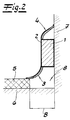
- Fig. 2 shows the core skirting board according to the invention installation in the area of a laminate flooring 5.
- This floor covering 5 is laid on a sub-floor 6 in such a way that between flooring 5 and wall 7 a Expansion joint 8 given width B results.
- the expansion joint is in Fig. 1, which shows the unassembled state, also hinted at.
- the width B of this expansion joint 8 is 20 mm in the exemplary embodiment.
- the figures show now that the material core 1 has such a thickness D. and the bottom edge profile 3 protrudes by such a dimension M, that with the core skirting board, the joint 8 of the given Width B between the laminate flooring 5 and the Wall 7 is bridged.
- the material core 1 according to the invention is essential is thicker than the material cores of conventional core skirting boards.
- the material core 1 has a thickness D, which approximately the overhang M of the floor end profile on the room side 3 corresponds, that is, the joint 8 becomes one Half of the material core 1 with its casing 2 and bridged by the sealing lip 3 to the other half.
- the material core 1 is approximately a thickness D has half the width 1 ⁇ 2 B of the one to be bridged Expansion joint 8 corresponds.
- the material core 1 has a thickness D of 10 mm on.
- Thickness d of approximately 11 mm, since the casing is on the wall side a thickness of 0.5 mm and a thickness of 0.4 mm on the room side having.
- the protrusion M of the sealing lip 3 is in unmounted condition in about 11 mm, so that - without the Projection L of the wall end profile 4 - a total thickness G the core skirting on the underside of 22 mm in unmounted condition.
- the core skirting can be assembled by gluing or nailing or screws. This is not shown in the figures shown.
Landscapes
- Engineering & Computer Science (AREA)
- Architecture (AREA)
- Civil Engineering (AREA)
- Structural Engineering (AREA)
- Floor Finish (AREA)
- Laminated Bodies (AREA)
- Building Environments (AREA)
- Transition And Organic Metals Composition Catalysts For Addition Polymerization (AREA)
- Acyclic And Carbocyclic Compounds In Medicinal Compositions (AREA)
Abstract
Description
- Fig. 1
- eine erfindungsgemäße Kernsockelleiste im Querschnitt in unmontiertem Zustand und
- Fig. 2
- den Gegenstand nach Fig. 1 nach erfolgter Montage im Bereich Wand/Boden.
Claims (8)
- Kernsockelleiste mit einem Werkstoffkern (1), einer Kunststoffummantelung (2) und einem an der Leistenunterseite angeordneten Bodenabschlussprofil (3) aus weichelastischem Material, welches raumseitig um ein vorgegebenes Maß (M) übersteht, dadurch gekennzeichnet, dass der Werkstoffkern (1) eine solche Dicke (D) aufweist und/oder das Bodenabschlussprofil (3) um ein solches Maß (M) übersteht, dass eine Dehnungsfuge (8) vorgegebener Breite (B) zwischen einem Bodenbelag (5) insbesondere einem Parkettboden oder Laminatboden oder dergleichen und einer zugeordneten Wand (7) überbrückbar ist.
- Kernsockelleiste nach Anspruch 1, dadurch gekennzeichnet, dass der Werkstoffkern (1) eine Dicke (D) aufweist, welche in etwa dem raumseitigen Überstand (M) des Bodenabschlussprofils (3) entspricht.
- Kernsockelleiste nach Anspruch 1 oder 2, dadurch gekennzeichnet, dass der Werkstoffkern (1) eine Dicke (D) aufweist, welche in etwa der halben Breite der zu überbrückenden Dehnungsfuge (8) entspricht.
- Kernsockelleiste nach einem der Ansprüche 1 bis 3, dadurch gekennzeichnet, dass der Werkstoffkern (1) eine Dicke (D) von 9 mm bis 11 mm, vorzugsweise 10 mm aufweist.
- Werkstoffkern nach einem der Ansprüche 1 bis 4, dadurch gekennzeichnet, dass der Werkstoffkern (1) mit der Kunststoffummantelung (2) eine Dicke (d) von 10 mm bis 12 mm, vorzugsweise 11 mm aufweist.
- Kernsockelleiste nach einem der Ansprüche 1 bis 5, dadurch gekennzeichnet, dass der Überstand (M) des Bodenabschlussprofils (3) 10 mm bis 12 mm, vorzugsweise 11 mm beträgt.
- Kernsockelleiste nach einem der Ansprüche 1 bis 6, dadurch gekennzeichnet, dass der Werkstoffkern (1) als Holzwerkstoffkern z. B. aus MDF, vorzugsweise aus einer MDF-Platte ausgebildet ist.
- Kernsockelleiste nach einem der Ansprüche 1 bis 7, dadurch gekennzeichnet, dass die Kunststoffummantelung (2) aus einem Polyolefin, vorzugsweise aus Polypropylen besteht und das Bodenabschlussprofil (3) aus weichelastischem Thermoplastmaterial auf Polyolefinbasis besteht.
Applications Claiming Priority (2)
| Application Number | Priority Date | Filing Date | Title |
|---|---|---|---|
| DE20206984U | 2002-05-03 | ||
| DE20206984U DE20206984U1 (de) | 2002-05-03 | 2002-05-03 | Kernsockelleiste |
Publications (3)
| Publication Number | Publication Date |
|---|---|
| EP1359267A2 true EP1359267A2 (de) | 2003-11-05 |
| EP1359267A3 EP1359267A3 (de) | 2006-08-30 |
| EP1359267B1 EP1359267B1 (de) | 2008-10-15 |
Family
ID=7970777
Family Applications (1)
| Application Number | Title | Priority Date | Filing Date |
|---|---|---|---|
| EP03008392A Expired - Lifetime EP1359267B1 (de) | 2002-05-03 | 2003-04-11 | Kernsockelleiste |
Country Status (3)
| Country | Link |
|---|---|
| EP (1) | EP1359267B1 (de) |
| AT (1) | ATE411436T1 (de) |
| DE (2) | DE20206984U1 (de) |
Cited By (4)
| Publication number | Priority date | Publication date | Assignee | Title |
|---|---|---|---|---|
| EP1719855A2 (de) * | 2005-05-06 | 2006-11-08 | W. Döllken & Co GmbH | Deckleiste, insbesondere Sockelleiste für den Wand/Boden-Übergang |
| US10550584B2 (en) * | 2009-07-27 | 2020-02-04 | Gregory A. Amundson | Flexible corner trim product |
| EP3808922A1 (de) * | 2019-10-15 | 2021-04-21 | APU Schönberg GmbH | Sockelleiste, deckenleiste und fenster- oder türstock-dämmleiste |
| EP3795775B1 (de) * | 2019-09-13 | 2022-08-24 | APU Schönberg GmbH | Sockelleiste, deckenleiste und fenster- oder türstock-dämmleiste |
Families Citing this family (3)
| Publication number | Priority date | Publication date | Assignee | Title |
|---|---|---|---|---|
| DE102005011439A1 (de) * | 2005-03-12 | 2006-09-14 | Rehau Ag + Co. | Dekorprofilkörper mit Dichtfunktion |
| DE202008015223U1 (de) | 2008-11-05 | 2010-03-25 | Sondermann, Frank | Sockelleiste zum Abdecken eines Belagsrandes |
| DE202012103084U1 (de) | 2012-08-15 | 2012-09-07 | W. Döllken & Co. GmbH | Kernsockelleiste |
Citations (1)
| Publication number | Priority date | Publication date | Assignee | Title |
|---|---|---|---|---|
| EP1114901A2 (de) | 2000-01-08 | 2001-07-11 | W. Döllken & Co GmbH | Kernsockelleiste |
Family Cites Families (3)
| Publication number | Priority date | Publication date | Assignee | Title |
|---|---|---|---|---|
| DE6750177U (de) * | 1968-09-02 | 1969-01-02 | Dynamit Nobel Ag | Sockelleiste |
| DE2100668C3 (de) * | 1971-01-08 | 1974-05-09 | Rich. Ermecke Ohg, 5944 Fleckenberg | Sockelleiste aus Holz mit einer allseitigen Kunststoffummantelung |
| DE19860319C2 (de) * | 1998-12-24 | 2001-05-17 | Theodor Rusler | Multifunktions-Fußbodenleiste |
-
2002
- 2002-05-03 DE DE20206984U patent/DE20206984U1/de not_active Expired - Lifetime
-
2003
- 2003-04-11 DE DE50310635T patent/DE50310635D1/de not_active Expired - Lifetime
- 2003-04-11 EP EP03008392A patent/EP1359267B1/de not_active Expired - Lifetime
- 2003-04-11 AT AT03008392T patent/ATE411436T1/de not_active IP Right Cessation
Patent Citations (1)
| Publication number | Priority date | Publication date | Assignee | Title |
|---|---|---|---|---|
| EP1114901A2 (de) | 2000-01-08 | 2001-07-11 | W. Döllken & Co GmbH | Kernsockelleiste |
Cited By (6)
| Publication number | Priority date | Publication date | Assignee | Title |
|---|---|---|---|---|
| EP1719855A2 (de) * | 2005-05-06 | 2006-11-08 | W. Döllken & Co GmbH | Deckleiste, insbesondere Sockelleiste für den Wand/Boden-Übergang |
| EP1719855A3 (de) * | 2005-05-06 | 2008-08-06 | W. Döllken & Co GmbH | Deckleiste, insbesondere Sockelleiste für den Wand/Boden-Übergang |
| US10550584B2 (en) * | 2009-07-27 | 2020-02-04 | Gregory A. Amundson | Flexible corner trim product |
| US11401720B2 (en) | 2009-07-27 | 2022-08-02 | Amundson Technology, Llc | Flexible corner trim product |
| EP3795775B1 (de) * | 2019-09-13 | 2022-08-24 | APU Schönberg GmbH | Sockelleiste, deckenleiste und fenster- oder türstock-dämmleiste |
| EP3808922A1 (de) * | 2019-10-15 | 2021-04-21 | APU Schönberg GmbH | Sockelleiste, deckenleiste und fenster- oder türstock-dämmleiste |
Also Published As
| Publication number | Publication date |
|---|---|
| DE20206984U1 (de) | 2002-09-12 |
| DE50310635D1 (de) | 2008-11-27 |
| EP1359267B1 (de) | 2008-10-15 |
| ATE411436T1 (de) | 2008-10-15 |
| EP1359267A3 (de) | 2006-08-30 |
Similar Documents
| Publication | Publication Date | Title |
|---|---|---|
| DE4215273C2 (de) | Belag zur Verkleidung von Boden-, Wand- und/oder Deckenflächen, insbesondere in der Art eines Riemenfußbodens | |
| DE10302727B4 (de) | Paneel, insbesondere Fußbodenpaneel | |
| WO2002001018A1 (de) | Fussbodenplatte | |
| DE29803708U1 (de) | Paneel, insbesondere für Fußbodenbeläge | |
| DE19636021C2 (de) | Verschalung oder Verkleidung | |
| WO2020182453A1 (de) | HARTES FUßBODENPANEEL ZUR SCHWIMMENDEN VERLEGUNG UNTER AUSBILDUNG EINES FUßBODENPANEELVERBUNDES | |
| DE20214622U1 (de) | Verlegesystem für Bodenplatten | |
| EP1114901B1 (de) | Kernsockelleiste | |
| EP1359267B1 (de) | Kernsockelleiste | |
| DE102004023158A1 (de) | Flächiges Element sowie Verfahren zur Bildung von seitlichen Verbindungsmitteln an miteinander verbindbaren flächigen Elementen | |
| DE102005044185A1 (de) | Decken- oder Wandverkleidungsplatte | |
| EP3015621B1 (de) | Sockelleiste, deckenleiste und fenster- oder türstock-dämmleiste sowie verfahren zum herstellen solcher leisten | |
| EP1709887B1 (de) | Eckverbinder für eine Leisteneckverkleidung | |
| DE102005039692A1 (de) | Halterung für eine Randleiste eines Fußbodens | |
| DE10220049A1 (de) | Vorrichtung zur Befestigung von Sockelleisten | |
| DE10302961B4 (de) | Wandabschlussleiste | |
| DE202007008087U1 (de) | Vorrichtung zur Ausbildung eines Anschlussüberganges zwischen zwei rechtwinklig aneinander angrenzenden Flächen mit starren Belägen | |
| DE10051404A1 (de) | Boden- oder Wandpaneel | |
| DE3729378C2 (de) | ||
| EP3399119A1 (de) | Vorrichtung zur dehnfugenverkleidung zwischen mit belägen verkleideten fussbodenabschnitten | |
| EP2527562A1 (de) | Verfahren zur Herstellung einer Eckverkleidung für den Stoßbereich eines Wandhochzuges und danach hergestellte Eckverkleidung | |
| EP1183138A1 (de) | Parkettlamelle, deren verwendung zur herstellung eines paneels oder parkettelementes, sowie hieraus hergestelltes parkettelement und verfahren zur herstellung einer parkettlamelle | |
| EP0405108A1 (de) | L-förmige Abschlussschiene | |
| EP1710371A1 (de) | Eckverkleidung für den Stossbereich eines Wandhochzuges | |
| DE10112958B4 (de) | Fussbodenpaneel |
Legal Events
| Date | Code | Title | Description |
|---|---|---|---|
| PUAI | Public reference made under article 153(3) epc to a published international application that has entered the european phase |
Free format text: ORIGINAL CODE: 0009012 |
|
| AK | Designated contracting states |
Kind code of ref document: A2 Designated state(s): AT BE BG CH CY CZ DE DK EE ES FI FR GB GR HU IE IT LI LU MC NL PT RO SE SI SK TR |
|
| AX | Request for extension of the european patent |
Extension state: AL LT LV MK |
|
| PUAL | Search report despatched |
Free format text: ORIGINAL CODE: 0009013 |
|
| AK | Designated contracting states |
Kind code of ref document: A3 Designated state(s): AT BE BG CH CY CZ DE DK EE ES FI FR GB GR HU IE IT LI LU MC NL PT RO SE SI SK TR |
|
| AX | Request for extension of the european patent |
Extension state: AL LT LV MK |
|
| 17P | Request for examination filed |
Effective date: 20061109 |
|
| 17Q | First examination report despatched |
Effective date: 20061205 |
|
| AKX | Designation fees paid |
Designated state(s): AT BE BG CH CY CZ DE DK EE ES FI FR GB GR HU IE IT LI LU MC NL PT RO SE SI SK TR |
|
| 17Q | First examination report despatched |
Effective date: 20061205 |
|
| GRAP | Despatch of communication of intention to grant a patent |
Free format text: ORIGINAL CODE: EPIDOSNIGR1 |
|
| RTI1 | Title (correction) |
Free format text: SKIRTING BOARD WITH A CORE |
|
| GRAS | Grant fee paid |
Free format text: ORIGINAL CODE: EPIDOSNIGR3 |
|
| GRAA | (expected) grant |
Free format text: ORIGINAL CODE: 0009210 |
|
| AK | Designated contracting states |
Kind code of ref document: B1 Designated state(s): AT BE BG CH CY CZ DE DK EE ES FI FR GB GR HU IE IT LI LU MC NL PT RO SE SI SK TR |
|
| REG | Reference to a national code |
Ref country code: GB Ref legal event code: FG4D Free format text: NOT ENGLISH Ref country code: CH Ref legal event code: EP |
|
| REG | Reference to a national code |
Ref country code: IE Ref legal event code: FG4D Free format text: LANGUAGE OF EP DOCUMENT: GERMAN |
|
| REF | Corresponds to: |
Ref document number: 50310635 Country of ref document: DE Date of ref document: 20081127 Kind code of ref document: P |
|
| REG | Reference to a national code |
Ref country code: SE Ref legal event code: TRGR |
|
| PG25 | Lapsed in a contracting state [announced via postgrant information from national office to epo] |
Ref country code: ES Free format text: LAPSE BECAUSE OF FAILURE TO SUBMIT A TRANSLATION OF THE DESCRIPTION OR TO PAY THE FEE WITHIN THE PRESCRIBED TIME-LIMIT Effective date: 20090126 Ref country code: BG Free format text: LAPSE BECAUSE OF FAILURE TO SUBMIT A TRANSLATION OF THE DESCRIPTION OR TO PAY THE FEE WITHIN THE PRESCRIBED TIME-LIMIT Effective date: 20090115 |
|
| PG25 | Lapsed in a contracting state [announced via postgrant information from national office to epo] |
Ref country code: SI Free format text: LAPSE BECAUSE OF FAILURE TO SUBMIT A TRANSLATION OF THE DESCRIPTION OR TO PAY THE FEE WITHIN THE PRESCRIBED TIME-LIMIT Effective date: 20081015 Ref country code: FI Free format text: LAPSE BECAUSE OF FAILURE TO SUBMIT A TRANSLATION OF THE DESCRIPTION OR TO PAY THE FEE WITHIN THE PRESCRIBED TIME-LIMIT Effective date: 20081015 Ref country code: PT Free format text: LAPSE BECAUSE OF FAILURE TO SUBMIT A TRANSLATION OF THE DESCRIPTION OR TO PAY THE FEE WITHIN THE PRESCRIBED TIME-LIMIT Effective date: 20090316 |
|
| REG | Reference to a national code |
Ref country code: IE Ref legal event code: FD4D |
|
| PG25 | Lapsed in a contracting state [announced via postgrant information from national office to epo] |
Ref country code: EE Free format text: LAPSE BECAUSE OF FAILURE TO SUBMIT A TRANSLATION OF THE DESCRIPTION OR TO PAY THE FEE WITHIN THE PRESCRIBED TIME-LIMIT Effective date: 20081015 Ref country code: DK Free format text: LAPSE BECAUSE OF FAILURE TO SUBMIT A TRANSLATION OF THE DESCRIPTION OR TO PAY THE FEE WITHIN THE PRESCRIBED TIME-LIMIT Effective date: 20081015 Ref country code: IE Free format text: LAPSE BECAUSE OF FAILURE TO SUBMIT A TRANSLATION OF THE DESCRIPTION OR TO PAY THE FEE WITHIN THE PRESCRIBED TIME-LIMIT Effective date: 20081015 Ref country code: RO Free format text: LAPSE BECAUSE OF FAILURE TO SUBMIT A TRANSLATION OF THE DESCRIPTION OR TO PAY THE FEE WITHIN THE PRESCRIBED TIME-LIMIT Effective date: 20081015 |
|
| PLBE | No opposition filed within time limit |
Free format text: ORIGINAL CODE: 0009261 |
|
| STAA | Information on the status of an ep patent application or granted ep patent |
Free format text: STATUS: NO OPPOSITION FILED WITHIN TIME LIMIT |
|
| PG25 | Lapsed in a contracting state [announced via postgrant information from national office to epo] |
Ref country code: CZ Free format text: LAPSE BECAUSE OF FAILURE TO SUBMIT A TRANSLATION OF THE DESCRIPTION OR TO PAY THE FEE WITHIN THE PRESCRIBED TIME-LIMIT Effective date: 20081015 |
|
| 26N | No opposition filed |
Effective date: 20090716 |
|
| PG25 | Lapsed in a contracting state [announced via postgrant information from national office to epo] |
Ref country code: SK Free format text: LAPSE BECAUSE OF FAILURE TO SUBMIT A TRANSLATION OF THE DESCRIPTION OR TO PAY THE FEE WITHIN THE PRESCRIBED TIME-LIMIT Effective date: 20081015 |
|
| BERE | Be: lapsed |
Owner name: W. DOLLKEN & CO. G.M.B.H. Effective date: 20090430 |
|
| REG | Reference to a national code |
Ref country code: CH Ref legal event code: PL |
|
| EUG | Se: european patent has lapsed | ||
| GBPC | Gb: european patent ceased through non-payment of renewal fee |
Effective date: 20090411 |
|
| NLV4 | Nl: lapsed or anulled due to non-payment of the annual fee |
Effective date: 20091101 |
|
| REG | Reference to a national code |
Ref country code: FR Ref legal event code: ST Effective date: 20091231 |
|
| PG25 | Lapsed in a contracting state [announced via postgrant information from national office to epo] |
Ref country code: CH Free format text: LAPSE BECAUSE OF NON-PAYMENT OF DUE FEES Effective date: 20090430 Ref country code: LI Free format text: LAPSE BECAUSE OF NON-PAYMENT OF DUE FEES Effective date: 20090430 |
|
| PG25 | Lapsed in a contracting state [announced via postgrant information from national office to epo] |
Ref country code: NL Free format text: LAPSE BECAUSE OF NON-PAYMENT OF DUE FEES Effective date: 20091101 |
|
| PG25 | Lapsed in a contracting state [announced via postgrant information from national office to epo] |
Ref country code: FR Free format text: LAPSE BECAUSE OF NON-PAYMENT OF DUE FEES Effective date: 20091222 Ref country code: GB Free format text: LAPSE BECAUSE OF NON-PAYMENT OF DUE FEES Effective date: 20090411 Ref country code: MC Free format text: LAPSE BECAUSE OF NON-PAYMENT OF DUE FEES Effective date: 20090430 |
|
| PG25 | Lapsed in a contracting state [announced via postgrant information from national office to epo] |
Ref country code: BE Free format text: LAPSE BECAUSE OF NON-PAYMENT OF DUE FEES Effective date: 20090430 |
|
| PG25 | Lapsed in a contracting state [announced via postgrant information from national office to epo] |
Ref country code: AT Free format text: LAPSE BECAUSE OF NON-PAYMENT OF DUE FEES Effective date: 20090411 |
|
| PG25 | Lapsed in a contracting state [announced via postgrant information from national office to epo] |
Ref country code: IT Free format text: LAPSE BECAUSE OF NON-PAYMENT OF DUE FEES Effective date: 20090411 |
|
| PG25 | Lapsed in a contracting state [announced via postgrant information from national office to epo] |
Ref country code: LU Free format text: LAPSE BECAUSE OF NON-PAYMENT OF DUE FEES Effective date: 20090411 |
|
| PG25 | Lapsed in a contracting state [announced via postgrant information from national office to epo] |
Ref country code: SE Free format text: LAPSE BECAUSE OF NON-PAYMENT OF DUE FEES Effective date: 20090412 |
|
| PG25 | Lapsed in a contracting state [announced via postgrant information from national office to epo] |
Ref country code: HU Free format text: LAPSE BECAUSE OF FAILURE TO SUBMIT A TRANSLATION OF THE DESCRIPTION OR TO PAY THE FEE WITHIN THE PRESCRIBED TIME-LIMIT Effective date: 20090416 |
|
| PG25 | Lapsed in a contracting state [announced via postgrant information from national office to epo] |
Ref country code: TR Free format text: LAPSE BECAUSE OF FAILURE TO SUBMIT A TRANSLATION OF THE DESCRIPTION OR TO PAY THE FEE WITHIN THE PRESCRIBED TIME-LIMIT Effective date: 20081015 |
|
| PG25 | Lapsed in a contracting state [announced via postgrant information from national office to epo] |
Ref country code: CY Free format text: LAPSE BECAUSE OF FAILURE TO SUBMIT A TRANSLATION OF THE DESCRIPTION OR TO PAY THE FEE WITHIN THE PRESCRIBED TIME-LIMIT Effective date: 20081015 |
|
| PG25 | Lapsed in a contracting state [announced via postgrant information from national office to epo] |
Ref country code: GR Free format text: LAPSE BECAUSE OF FAILURE TO SUBMIT A TRANSLATION OF THE DESCRIPTION OR TO PAY THE FEE WITHIN THE PRESCRIBED TIME-LIMIT Effective date: 20081015 |
|
| REG | Reference to a national code |
Ref country code: DE Ref legal event code: R082 Ref document number: 50310635 Country of ref document: DE Representative=s name: ANDREJEWSKI - HONKE PATENT- UND RECHTSANWAELTE, DE Ref country code: DE Ref legal event code: R081 Ref document number: 50310635 Country of ref document: DE Owner name: DOELLKEN-KUNSTSTOFFVERARBEITUNG GMBH, DE Free format text: FORMER OWNER: W. DOELLKEN & CO. GMBH, 45964 GLADBECK, DE Ref country code: DE Ref legal event code: R081 Ref document number: 50310635 Country of ref document: DE Owner name: DOELLKEN-WEIMAR GMBH, DE Free format text: FORMER OWNER: W. DOELLKEN & CO. GMBH, 45964 GLADBECK, DE Ref country code: DE Ref legal event code: R081 Ref document number: 50310635 Country of ref document: DE Owner name: DOELLKEN PROFILES GMBH, DE Free format text: FORMER OWNER: W. DOELLKEN & CO. GMBH, 45964 GLADBECK, DE |
|
| REG | Reference to a national code |
Ref country code: DE Ref legal event code: R082 Ref document number: 50310635 Country of ref document: DE Representative=s name: ANDREJEWSKI - HONKE PATENT- UND RECHTSANWAELTE, DE Ref country code: DE Ref legal event code: R081 Ref document number: 50310635 Country of ref document: DE Owner name: DOELLKEN-WEIMAR GMBH, DE Free format text: FORMER OWNER: DOELLKEN-KUNSTSTOFFVERARBEITUNG GMBH, 45964 GLADBECK, DE Ref country code: DE Ref legal event code: R081 Ref document number: 50310635 Country of ref document: DE Owner name: DOELLKEN PROFILES GMBH, DE Free format text: FORMER OWNER: DOELLKEN-KUNSTSTOFFVERARBEITUNG GMBH, 45964 GLADBECK, DE |
|
| REG | Reference to a national code |
Ref country code: DE Ref legal event code: R082 Ref document number: 50310635 Country of ref document: DE Representative=s name: ANDREJEWSKI HONKE PATENT- UND RECHTSANWAELTE P, DE Ref country code: DE Ref legal event code: R082 Ref document number: 50310635 Country of ref document: DE Representative=s name: ANDREJEWSKI - HONKE PATENT- UND RECHTSANWAELTE, DE Ref country code: DE Ref legal event code: R081 Ref document number: 50310635 Country of ref document: DE Owner name: DOELLKEN PROFILES GMBH, DE Free format text: FORMER OWNER: DOELLKEN-WEIMAR GMBH, 99428 NOHRA, DE |
|
| REG | Reference to a national code |
Ref country code: DE Ref legal event code: R082 Ref document number: 50310635 Country of ref document: DE Representative=s name: ANDREJEWSKI HONKE PATENT- UND RECHTSANWAELTE P, DE Ref country code: DE Ref legal event code: R081 Ref document number: 50310635 Country of ref document: DE Owner name: DOELLKEN PROFILES GMBH, DE Free format text: FORMER OWNER: DOELLKEN PROFILES GMBH, 99428 NOHRA, DE |
|
| PGFP | Annual fee paid to national office [announced via postgrant information from national office to epo] |
Ref country code: DE Payment date: 20220307 Year of fee payment: 20 |
|
| REG | Reference to a national code |
Ref country code: DE Ref legal event code: R071 Ref document number: 50310635 Country of ref document: DE |