EP1359035B1 - Luftauslassdüse - Google Patents
Luftauslassdüse Download PDFInfo
- Publication number
- EP1359035B1 EP1359035B1 EP03008518A EP03008518A EP1359035B1 EP 1359035 B1 EP1359035 B1 EP 1359035B1 EP 03008518 A EP03008518 A EP 03008518A EP 03008518 A EP03008518 A EP 03008518A EP 1359035 B1 EP1359035 B1 EP 1359035B1
- Authority
- EP
- European Patent Office
- Prior art keywords
- outlet
- air
- displacer
- accordance
- air outlet
- Prior art date
- Legal status (The legal status is an assumption and is not a legal conclusion. Google has not performed a legal analysis and makes no representation as to the accuracy of the status listed.)
- Expired - Lifetime
Links
Images


Classifications
-
- F—MECHANICAL ENGINEERING; LIGHTING; HEATING; WEAPONS; BLASTING
- F24—HEATING; RANGES; VENTILATING
- F24F—AIR-CONDITIONING; AIR-HUMIDIFICATION; VENTILATION; USE OF AIR CURRENTS FOR SCREENING
- F24F13/00—Details common to, or for air-conditioning, air-humidification, ventilation or use of air currents for screening
- F24F13/02—Ducting arrangements
- F24F13/06—Outlets for directing or distributing air into rooms or spaces, e.g. ceiling air diffuser
- F24F13/062—Outlets for directing or distributing air into rooms or spaces, e.g. ceiling air diffuser having one or more bowls or cones diverging in the flow direction
-
- B—PERFORMING OPERATIONS; TRANSPORTING
- B60—VEHICLES IN GENERAL
- B60H—ARRANGEMENTS OF HEATING, COOLING, VENTILATING OR OTHER AIR-TREATING DEVICES SPECIALLY ADAPTED FOR PASSENGER OR GOODS SPACES OF VEHICLES
- B60H1/00—Heating, cooling or ventilating devices
- B60H1/34—Nozzles; Air-diffusers
- B60H1/345—Nozzles; Air-diffusers with means for adjusting divergence, convergence or oscillation of air stream
Definitions
- the invention relates to an air outlet nozzle after the The preamble of claim 1 as disclosed in DE 19807292.
- Air outlet nozzles used with control devices that have a allow targeted control of the exiting air jet.
- a vehicle occupant steers a focused one and tempered air jet after a certain time of itself away, to avoid unpleasant drafts.
- the heating or cooling capacity must be increased, to create a comfortable for the occupant temperature, since the air jet not the occupants directly, but primarily other things in the vehicle heats or cools. Will the inmate in contrast directly illuminated with a diffuse air jet, so Drafts are avoided and the heating or Cooling capacity can be reduced.
- an air outlet nozzle which has three mutually displaceable Heilleitgitter.
- the Air grilles are in the air outlet level of Air outlet arranged, with a grille firmly with the nozzle is connected and two of the grid parallel to the fixed mounted air grille are displaced.
- By the Moving the air grilles form differently inclined air ducts, so that the exit direction of the Air jet is controllable.
- the disadvantage here is that the Air grille have a high flow resistance and that only the air outlet direction, but not the Spreading of the air jet is controllable.
- an air outlet is known, the one rotationally symmetrical housing and a rigid baffle plate having. This is fixed in the outlet cross section of the Air outlet arranged. Inside the case are radial arranged circumferentially swirl vanes. By axial displacement the swirl vanes inside the air outlet can the Diffusivity of the exiting air jet can be controlled.
- the disadvantage here is the high flow obstruction by the Swirl vanes, which results in large losses.
- GB 624,932 shows an air outlet nozzle with a fixed baffle plate and a housing with radial Air intake. Inside the housing are air guide elements arranged axially adjustable. Depending on the axial position of the Air guide elements guide these together with the baffle plate radially in the nozzle housing incoming air in the area between 180 and 90 degrees around, making the air adjustable emerges radially or axially.
- the disadvantage here is the through radial air inlet direction caused relatively large volume of construction the air nozzle. Also, the flow resistance of this Air outlet nozzle due to the air deflection relatively high.
- the present invention is based on the object, a Air outlet nozzle with adjustable diffuser air jet to create a compact, as well as a large one achievable air jet spread at low Has flow losses
- the Air outlet nozzle easy and / or comfortable to use and have low noise.
- a Displacer In the mouth area of the air outlet nozzle is a Displacer arranged, which is axially displaceable, i. in the direction of the central longitudinal axis of the air outlet nozzle is displaceable, and an adjustable Strömungsversperrung having.
- the displacement body can in the mouth of the Air nozzle may be arranged in the air outlet plane or else be brought out of the mouth area out, so that it is arranged outside the nozzle housing.
- Displacement body may have this swiveling blades, which are preferably arranged V-shaped or annular.
- the displacement body have an elastic membrane, with the lamellae or interacts with bars or rod-shaped slats and a rounded outer contour of the displacement body forms.
- the entire outer contour or individual Boundary surfaces of the displacement body of the elastic Membrane are formed.
- An embodiment of the invention provides an air-permeable Displacement body before, the air permeability adjustable is.
- the air permeability can be adjustable so that the Displacer in undressed position, d. H. in the Area of the mouth level, minimum flow resistance, d. H. has maximum air permeability and / or in extended Position, d. H. outside the nozzle housing, maximum Flow resistance, d. H. minimal air permeability having.
- the displacement body can handle different flow profiles to allow a homogeneous over its cross section or one have inhomogeneous air permeability.
- the displacement body is an inhomogeneous Air permeability, d. H. in locally defined areas having different air permeability.
- the displacement body can be several layered perforated plates with differently divided hole pattern or grid with have different pitch, so depending on the position the perforated plates or grid to each other a local different air permeability can be adjusted. This is a distraction of the air jet in a certain Direction possible.
- the inhomogeneous Air permeability of the displacer one in time variable, preferably periodic control of Outlet direction of the air steel possible. By tilting the Displacement body with respect to the nozzle outlet cross-section is also a direction setting of the exiting Air jet possible.
- An embodiment of the invention provides that the Displacer connected to a nozzle orifice element is, which is axially pulled out of the nozzle housing.
- the Side walls of the nozzle orifice element have recesses for radial escape of air, leaving no or only one low flow obstruction occurs. It is provided that the nozzle orifice element substantially the same cross section and / or diameter as the nozzle housing, wherein the Cross section and / or diameter of the nozzle orifice element be slightly larger or smaller than that of the nozzle housing can, leaving the walls of the nozzle orifice element positively within or outside of the nozzle housing its side walls abut.
- the nozzle orifice member may also be over on the side walls of the Nozzle housing arranged guide rails axially displaceable be stored. Similarly, a central, centered in the Be provided nozzle housing arranged guide rail.
- the displacement body at a fixed position outside the nozzle housing or in the Be arranged outlet port.
- the nozzle housing having an adjusting device.
- the adjusting device can mechanical and / or electrical and / or mechatronic Actuators for adjusting the position and / or shape and / or the Cross-section and / or the air permeability of Have displacement body.
- the Adjusting device mechanically and / or automatically operated, preferably remotely controllable, so that the exit direction and / or diffusivity of the air jet over the Adjustment device manually and / or after a preselected Program sequence or timing is controllable.
- An application of the air outlet nozzle is particularly suitable for heating and / or air conditioning and / or ventilation systems for vehicles intended.
- Air outlet of the heating and / or air conditioning control so that in addition to a directional air outlet at high speed, a diffused air outlet with low speed is adjustable to z. B. unpleasant drafts avoid.
- the air outlet nozzle must be comfortable, d. H. To be as quiet as possible and should be as little space claim.
- an air outlet nozzle 1 is shown schematically.
- the air outlet 1 can z. B. in the cockpit area or in a center console be designed as Heilauslassdüse a heating and / or air conditioning of a passenger car.
- the air outlet nozzle 1 has a housing 11 at the end an air duct or an air distribution system is arranged. On the downstream side of the housing 11, the Heilauslassdüse 1 an outlet port 12 with a Displacer 13 on. The displacement body 13 is with a nozzle orifice member 14 is connected.
- the central longitudinal axis 21 of the air outlet nozzle is shown in dashed lines and runs approximately at right angles to the mouth plane that runs along the Line A - A runs.
- the nozzle orifice member 14 has side walls which are the same shaped cross-section at slightly larger dimensions such as have the housing 11.
- the side walls of the Nozzle orifice element 14 thus comprises the housing 11 positively and are mounted axially displaceable thereon. So can the nozzle orifice member 14 together with the thereto fixed displacer 13 forward, z. B. in one Vehicle interior into being moved.
- the side walls the nozzle orifice member 14 have in the front, to the Displacer 13 directed towards section, recesses on, allowing the most unhindered flow of air in allow predominantly radial direction.
- a drive device 18 engages between the nozzle housing 11 and the nozzle orifice member 14 for shifting the Nozzle orifice element and / or for controlling the Air permeability of the displacement body 13, so that the Characteristics of the air outlet nozzle automatically driven is changeable.
- the drive device 18 is provided with a Control device 17 which is a control element 20 for manually controlling the air outlet nozzle 1.
- the control device 17 the Air outlet 1 also programmable or Timed control, so that from the air outlet 1 escaping air jet using pre-selectable programs or Timing is controlled automatically.
- the air outlet nozzle 1 is controllable by the control device 17 such that the Air jet the concerns of a heating and / or cooling phase a connected heating and / or air conditioning optimally equivalent.
- the control device 17th to connect with an automatic climate control or in such an automatic integrate.
- the displacement body 13 with the Nozzle orifice member 14 in a retracted position, so that the displacement body 13 flush with the housing 11th completes.
- the recesses in the side walls of the nozzle orifice member 14 are of the nozzle housing 11th covered.
- the air jet enters the Figures indicated by arrows, focused in the axial direction from the air outlet 1 from.
- the flow resistance of the Displacement body 13 is for maximum air flow rate minimally adjusted.
- the Displacer 13 closes the nozzle orifice member 14 to Interior down.
- the recesses of the nozzle orifice element 14 are no longer from the side walls of the nozzle housing 11 concealed but freely permeable, so that from the Air outlet 1 exiting air flow in approximately Radial direction can escape through the same. In this Position occurs the air jet diffuse.
- the Beam widening be controlled such that different amounts of air through the displacement body on the one hand and the recesses on the other.
- Ratio determines the diffusivity of the air flow.
- This Ratio can be determined by the variables of position and / or Strömungsversperrung of the displacement body in conjunction with adjust the cross section and the arrangement of the recesses.
- the recesses in the side walls of the Nozzle orifice element 14 has a comparable cross-sectional area as the nozzle cross-section itself, arise itself at maximum beam expansion hardly additional losses, in Comparison with a freely permeable air nozzle known Design type. Due to this beam expansion in combination with low pressure losses, the air outlet 1 in principle Flow characteristics of an air outlet nozzle with essential larger cross-section, so that de facto a Enlargement of the nozzle cross-section with constant Nozzle dimensions results.
- FIG. 3 shows an example of the displacement body 13 with three gratings 19a, 19b and 19c arranged one behind the other in the flow direction.
- the individual grids 19a, 19b and 19c are arranged parallel to one another and designed to be displaceable relative to one another.
- the grid arrangement with the least flow obstruction, ie the largest air permeability of the displacement body 13 is shown, as he z. B. is usually used with focused air jet. All three grids 19a, 19b and 19c are arranged in alignment one behind the other, so that a maximum freely flowable surface results between the grid struts.
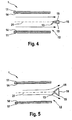
- FIGS. 4 and 5 show an exemplary embodiment of the air outlet nozzle 1 with a shape-variable displacement body 13.
- the Beerauslassdüse 1 is constructed as described above, but here the nozzle orifice member 14 is disposed in the nozzle housing 11 inside.
- the displacement body 13 is connected via not shown connecting webs with the nozzle orifice member 14 and can be moved by moving the nozzle orifice member 14 in the axial direction.
- the displacement body 13 has two fins 15, the V-shaped arranged and pivotally connected to each other.
- the pointed end of the V-shaped slats points to Flow into the interior of the air outlet nozzle 1.
- the fins 15 are enveloped by an elastic membrane 16, which the Outer contour of the displacement body 13 forms.
- FIG 4 is a position of the fins 15 with low Flow resistance or cross section of the displacement body 13 shown.
- the air jet occurs here essentially axially from the housing 11 of the air nozzle 1 and is characterized by the Displacement body 13 only slightly influenced.
- For minimal Strahlauf termed the slats 15 can parallel to each other be aligned.
- Figure 5 is a position of the fins 15 with larger Flow resistance or cross section of the displacement body 13 shown.
- the air jet is here by the Displacer 13 radially deflected so that it widened becomes.
Landscapes
- Engineering & Computer Science (AREA)
- Mechanical Engineering (AREA)
- Physics & Mathematics (AREA)
- Thermal Sciences (AREA)
- Chemical & Material Sciences (AREA)
- Combustion & Propulsion (AREA)
- General Engineering & Computer Science (AREA)
- Air-Flow Control Members (AREA)
- Duct Arrangements (AREA)
- Nozzles (AREA)
Description
- Figur 1:
- eine schematische Darstellung einer Luftauslassdüse mit fokussiertem Luftstrahl,
- Figur 2:
- eine schematische Darstellung der Luftauslassdüse mit diffusem Luftstrahl,
- Figur 3:
- eine schematische Darstellung eines Verdrängungskörpers mit einstellbarer Luftdurchlässigkeit,
- Figur 4:
- eine schematische Darstellung einer Luftauslassdüse mit einem formveränderbaren Verdrängungskörper und fokussiertem Luftstrahl,
- Figur 5:
- eine schematische Darstellung einer Luftauslassdüse mit einem formveränderbaren Verdrängungskörper und diffusem Luftstrahl.
Claims (20)
- Luftauslassdüse für eine Lüftungsanlage, insbesondere in einem Fahrzeug,
mit einem eine Auslassmündung aufweisenden Düsengehäuse mit Düsenmündungselement und einem im Mündungsbereich in der Luftströmung angeordneten Verdrängungskörper, der mit dem Düsenmündungselement verbunden ist,
dass die Position des Verdrängungskörpers (13) in axialer Richtung relativ zu der Auslassmündung (12) einstellbar ist, indem er von einer Position in der Auslassmündung (12) in eine Position außerhalb des Düsengehäuses (11) verschiebbar ist,
dadurch gekennzeichnet, dass der Verdrängungskörper (13) eine einstellbare Strömungsversperrung aufweist. - Luftauslassdüse nach Anspruch 1,
dadurch gekennzeichnet, dass der Verdrängungskörper (13) in der Position in der Auslassmündung (12) minimale Strömungsversperrung aufweist. - Luftauslassdüse nach Anspruch 1 oder 2,
dadurch gekennzeichnet, dass der Verdrängungskörper (13) in einer Position außerhalb des Düsengehäuses (11) hohe Strömungsversperrung aufweist. - Luftauslassdüse nach einem der Ansprüche 1 bis 3,
dadurch gekennzeichnet, dass der Verdrängungskörper (13) einen einstellbaren Querschnitt und/oder eine einstellbare variable Form aufweist. - Luftauslassdüse nach einem der Ansprüche 1 bis 4,
dadurch gekennzeichnet, dass der Verdrängungskörper (13) verstellbare Lamellen (15) oder Stäbe aufweist, wobei die Lamellen (15) vorzugsweise V-förmig angeordnet sind. - Luftauslassdüse nach einem der Ansprüche 1 bis 5,
dadurch gekennzeichnet, dass der Verdrängungskörper (13) eine elastische Membran (16) aufweist. - Luftauslassdüse nach Anspruch 5 oder 6,
dadurch gekennzeichnet, dass die Membran (16) und/oder die Lamellen (15) und/oder Stäbe zum Einstellen von unterschiedlich geformten Begrenzungsflächen und/oder Querschnitten des Verdrängungskörpers (13) ausgebildet ist bzw. sind. - Luftauslassdüse nach einem der Ansprüche 1 bis 3,
dadurch gekennzeichnet, dass der Verdrängungskörper (13) eine einstellbare Luftdurchlässigkeit aufweist. - Luftauslassdüse nach Anspruch 8,
dadurch gekennzeichnet, dass der Verdrängungskörper (13) eine über seinen Querschnitt homogene Luftdurchlässigkeit aufweist. - Luftauslassdüse nach Anspruch 8,
dadurch gekennzeichnet, dass der Verdrängungskörper (13) eine in lokal abgegrenzten Flächen unterschiedlich einstellbare Luftdurchlässigkeit aufweist. - Luftauslassdüse nach einem der Ansprüche 8 bis 10,
dadurch gekennzeichnet, dass der Verdrängungskörper (13) mehrere, vorzugsweise drei gegeneinander verschiebbare Gitter (19a, 19b, 19c) und/oder Lochbleche aufweist. - Luftauslassdüse nach einem der Ansprüche 8 bis 11,
dadurch gekennzeichnet, dass das Düsenmündungselement (14) in axialer Richtung aus dem Düsengehäuse (11) ausziehbar ausgebildet ist, indem das Düsenmündungselement (14) Seitenwände aufweist, die so ausgebildet sind, dass das Düsenmündungselement (14) weitgehend gleichen Querschnitt bei geringfügig größeren oder kleineren Dimensionen wie das Düsengehäuse (11) aufweist und dessen Seitenwände an Wänden des Düsengehäuses (11) formschlüssig anliegend geführt sind. - Luftauslassdüse nach einem der Ansprüche 8 bis 11,
dadurch gekennzeichnet, dass das Düsenmündungselement (14) in axialer Richtung aus dem Düsengehäuse (11) ausziehbar ausgebildet ist, indem das Düsenmündungselement (14) über Schienen in dem Düsengehäuse (11) verschiebbar gelagert ist, wobei die Schienen zwischen Düsengehäusewand und Düsenmündungselement (14) oder an zentraler Stelle in dem Düsengehäuse (11) entlang der Mittellängsachse (21) verlaufend angeordnet sind. - Luftauslassdüse nach Anspruch 12,
dadurch gekennzeichnet, dass die Seitenwände des Düsenmündungselementes (14) im Bereich des Verdrängungskörpers (13) Aussparungen aufweist, die zum radialen Austritt von Luft ausgebildet sind. - Luftauslassdüse nach Anspruch 14,
dadurch gekennzeichnet, dass die Aussparungen des Düsenmündungselementes (14) bei eingeschobenem Düsenmündungselement (14) von dem Düsengehäuse (11) abgedeckt sind und bei ausgezogenem Düsenmündungselement (14) frei durchströmbar sind. - Luftauslassdüse nach einem der Ansprüche 8 bis 15,
dadurch gekennzeichnet, dass der Verdrängungskörper (13) am äußeren Ende des Düsenmündungselements (14) angeordnet ist und den Querschnitt des Düsenmündungselements (14) zumindest teilweise abdeckt, vorzugsweise senkrecht zu dessen Seitenwänden angeordnet ist. - Luftauslassdüse nach einem der Ansprüche 1 bis 16,
dadurch gekennzeichnet, dass das Düsengehäuse (11) eine Verstellvorrichtung (17) zum Einstellen der Strömungsversperrung, vorzugsweise der Luftdurchlässigkeit und/oder der Position und/oder der Form, des Verdrängungskörpers (13) aufweist. - Luftauslassdüse nach Anspruch 17,
dadurch gekennzeichnet, dass die Verstellvorrichtung (17) ein manuelles Bedienelement (20) aufweist oder mit einem solchen verbunden ist, das zum manuellen Verstellen der Strömungsversperrung, vorzugsweise der Luftdurchlässigkeit und/oder der Position und/oder der Form des Verdrängungskörpers (13) ausgebildet ist. - Luftauslassdüse nach Anspruch 17 oder 18,
dadurch gekennzeichnet, dass die Verstellvorrichtung (17) zum automatischen Verstellen der Strömungsversperrung, vorzugsweise der Luftdurchlässigkeit und/oder der Position und/oder der Form des Verdrängungskörpers (13) ausgebildet ist, vorzugsweise nach einem vorgebbaren Zeitablauf und/oder Programmablauf. - Luftauslassdüse nach einem der Ansprüche 17 bis 19,
dadurch gekennzeichnet, dass die Verstellvorrichtung (17) die Strömungsversperrung, vorzugsweise die Luftdurchlässigkeit und/oder die Position und/oder die Form des Verdrängungskörpers (13) so steuert, dass bei jeder Einstellung der durch den Verdrängungskörper (13) hervorgerufene Druckverlust gleich groß ist, so dass die ausströmende Luftmenge konstant ist.
Applications Claiming Priority (2)
| Application Number | Priority Date | Filing Date | Title |
|---|---|---|---|
| DE10219696A DE10219696B4 (de) | 2002-05-02 | 2002-05-02 | Luftauslassdüse |
| DE10219696 | 2002-05-02 |
Publications (3)
| Publication Number | Publication Date |
|---|---|
| EP1359035A2 EP1359035A2 (de) | 2003-11-05 |
| EP1359035A3 EP1359035A3 (de) | 2004-11-10 |
| EP1359035B1 true EP1359035B1 (de) | 2005-10-05 |
Family
ID=28798974
Family Applications (1)
| Application Number | Title | Priority Date | Filing Date |
|---|---|---|---|
| EP03008518A Expired - Lifetime EP1359035B1 (de) | 2002-05-02 | 2003-04-12 | Luftauslassdüse |
Country Status (3)
| Country | Link |
|---|---|
| US (1) | US6805624B2 (de) |
| EP (1) | EP1359035B1 (de) |
| DE (2) | DE10219696B4 (de) |
Families Citing this family (29)
| Publication number | Priority date | Publication date | Assignee | Title |
|---|---|---|---|---|
| DE10114524B4 (de) * | 2001-03-21 | 2004-02-19 | Bombardier Transportation Gmbh | Verfahren und Anordnung zur Klimatisierung schnellfahrender Fahrzeuge |
| WO2004080739A1 (de) | 2003-03-13 | 2004-09-23 | Behr Gmbh & Co. Kg | Luftausströmer, insbesondere für ein kraftfahrzeug und ein zugehöriges luftausströmverfahren |
| DE10353182A1 (de) * | 2003-11-13 | 2005-06-16 | Behr Gmbh & Co. Kg | Düsenanordnung, insbesondere für ein Kraftfahrzeug |
| DE102004003196A1 (de) * | 2004-01-22 | 2005-08-18 | Daimlerchrysler Ag | Belüftungseinrichtung für ein Kraftfahrzeug |
| DE102004023495A1 (de) | 2004-05-10 | 2005-12-08 | Behr Gmbh & Co. Kg | Luftströmung, insbesondere für ein Kraftfahrzeug |
| FR2877271B1 (fr) * | 2004-11-03 | 2007-02-02 | Faurecia Interieur Ind Snc | Aerateur de systeme de ventilation de l'habitacle d'un vehicule |
| DE102004057316A1 (de) * | 2004-11-27 | 2006-06-01 | Fischer Automotive Systems Gmbh | Lufteinleitvorrichtung |
| DE102005029340B3 (de) * | 2005-06-24 | 2007-03-08 | Daimlerchrysler Ag | Luftauslassdüse |
| DE102005050250B4 (de) * | 2005-10-20 | 2014-08-21 | Volkswagen Ag | Luftausströmer für die Klimatisierung eines Fahrzeuginnenraumes |
| DE102006017376A1 (de) * | 2006-04-11 | 2007-10-18 | Behr Gmbh & Co. Kg | Luftzuführungskanal |
| JP4506758B2 (ja) * | 2006-05-23 | 2010-07-21 | トヨタ自動車株式会社 | 空調装置の吹出口構造 |
| US7980929B2 (en) * | 2007-02-06 | 2011-07-19 | Toyota Motor Engineering & Manufacturing North America, Inc. | Instrument panel vent |
| FR2912960B1 (fr) * | 2007-02-28 | 2009-05-22 | Faurecia Interieur Ind Snc | Aerateur d'un systeme de ventilation d'un vehicule automobile et planche de bord de vehicule ainsi equipee. |
| SE531336C2 (sv) * | 2007-07-02 | 2009-02-24 | Scania Cv Ab | Luftutsläppsdysa |
| DE102007049141A1 (de) * | 2007-10-12 | 2009-04-16 | Bayerische Motoren Werke Aktiengesellschaft | Luftausströmeinrichtung für Fahrzeugklimaanlagen |
| DE102008035154B3 (de) * | 2008-07-28 | 2009-09-17 | AKT altmärker Kunststoff-Technik GmbH | Luftauslassdüse |
| DE102009005891B4 (de) * | 2009-01-23 | 2015-03-26 | Audi Ag | Luftausströmer für ein Belüftungssystem eines Kraftfahrzeugs |
| DE102009017911B4 (de) * | 2009-04-17 | 2013-09-19 | Airbus Operations Gmbh | Luftauslass, Ruheraum, Verwendung eines Luftauslasses und Fahrzeug |
| JP5597423B2 (ja) * | 2009-05-29 | 2014-10-01 | 豊田合成株式会社 | 空調用レジスタ |
| DE102010002083A1 (de) * | 2010-02-18 | 2011-08-18 | Behr GmbH & Co. KG, 70469 | Vorrichtung |
| DE102012224482A1 (de) * | 2012-12-28 | 2014-07-03 | Behr Gmbh & Co. Kg | Luftausströmdüse |
| EP3306217B1 (de) * | 2016-10-04 | 2020-02-12 | Lindinvent AB | Zuluftvorrichtung zur steuerung des zuluftstroms |
| DE102017218610A1 (de) * | 2017-10-18 | 2019-04-18 | Bayerische Motoren Werke Aktiengesellschaft | Luftausströmeinheit |
| JP6869196B2 (ja) * | 2018-01-25 | 2021-05-12 | しげる工業株式会社 | 車両用レジスタ装置 |
| EP3693198B1 (de) * | 2019-02-07 | 2021-05-19 | Ningbo Geely Automobile Research & Development Co. Ltd. | Entlüftungsvorrichtung für ein belüftungssystem eines fahrzeugs |
| CN110108014A (zh) * | 2019-05-17 | 2019-08-09 | 太原理工大学 | 角式自控送风系统 |
| KR102907535B1 (ko) | 2021-01-18 | 2026-01-05 | 현대모비스 주식회사 | 차량용 메쉬형 에어벤트 장치 |
| US12098861B1 (en) * | 2024-01-31 | 2024-09-24 | King Faisal University | Smart vent/duct cover for controlling and cooling temperatures individual rooms |
| DE102024118208A1 (de) | 2024-06-27 | 2025-03-20 | Audi Aktiengesellschaft | Luftausströmer für ein Kraftfahrzeug, Fahrzeugkomponente mit einem solchen Luftausströmer und Kraftfahrzeug mit einer solchen Fahrzeugkomponente |
Family Cites Families (28)
| Publication number | Priority date | Publication date | Assignee | Title |
|---|---|---|---|---|
| US261476A (en) * | 1882-07-18 | Damper | ||
| US184955A (en) * | 1876-12-05 | Improvement in ventilating-skylights for vessels | ||
| US2367104A (en) * | 1943-02-06 | 1945-01-09 | Demuth Charles | Variable volume air distributor |
| GB624932A (en) * | 1947-07-12 | 1949-06-20 | Frederick Charles Stewart | Improvements in air distributor devices |
| US2558421A (en) * | 1948-03-05 | 1951-06-26 | W B Connor Engineering Corp | Diffuser with a detachable deflector member |
| US3000291A (en) * | 1958-01-20 | 1961-09-19 | Sandor J Zsarnoti | Ventilator-air purifier combination |
| US3082676A (en) * | 1959-06-30 | 1963-03-26 | Carrier Corp | Air distributing unit |
| US3299797A (en) * | 1964-09-02 | 1967-01-24 | John P Dry | Combined air diffuser and lighting fixture |
| US3554111A (en) * | 1968-11-29 | 1971-01-12 | Carrier Corp | Air conditioning terminal |
| US3600856A (en) * | 1970-02-09 | 1971-08-24 | Eldon L Burn | Closure mechanism for panel opening |
| US3765316A (en) * | 1971-04-05 | 1973-10-16 | E Skoch | Adjustable and closeable air diffuser |
| US3732799A (en) * | 1971-06-11 | 1973-05-15 | Anlibema Ltd | Air conditioning terminal units |
| US3799046A (en) * | 1972-04-06 | 1974-03-26 | Mitco Corp | Diffuser valve |
| SE419127B (sv) * | 1979-11-26 | 1981-07-13 | Gemla Plast Ab | Luftdon for tillforsel av obehandlad uteluft till ett rum |
| CH664806A5 (fr) * | 1985-07-01 | 1988-03-31 | Marius Thiebaud | Soupape automatique de regulation du debit d'air soutire d'un local par une installation de ventilation mecanique. |
| SE451444B (sv) * | 1986-09-29 | 1987-10-12 | Saab Scania Ab | Munstycke for utslepp av ventilationsluft fran ventilationssystem |
| US4800804A (en) * | 1987-08-06 | 1989-01-31 | Tennessee Plastics, Inc. | Variable air flow diffuser |
| ES2057573T3 (es) * | 1989-07-04 | 1994-10-16 | Laszlo Sandor | Dispositivo para regular el flujo de medios gaseosos o liquidos, especialmente aire. |
| ES2032645T3 (es) * | 1989-09-12 | 1993-02-16 | Siemens Aktiengesellschaft | Tobera de corriente de salida para instalaciones de ventilacion y de aire acondicionado. |
| DE4139099C2 (de) * | 1991-11-28 | 1997-04-30 | Krantz Tkt Gmbh | Luftauslaß |
| US5385503A (en) * | 1992-12-01 | 1995-01-31 | Bowles Fluidics Corporation | Temperature controller air outlet |
| US5333835A (en) * | 1993-07-22 | 1994-08-02 | American Standard Inc. | Electric motor driven air valve |
| DE19612764C2 (de) * | 1996-03-30 | 1999-04-15 | Mueller Erwin Gmbh & Co | Luftauslaß, insbesondere Deckenluftauslaß |
| US5800259A (en) * | 1996-09-03 | 1998-09-01 | B & B Molders, L.L.C. | Grill assembly |
| DE19648736C1 (de) * | 1996-11-25 | 1998-01-15 | Daimler Benz Ag | Belüftungsdüse |
| DE19807292B4 (de) * | 1997-03-01 | 2007-09-13 | Volkswagen Ag | Belüftungsvorrichtung für einen Innenraum |
| US6149513A (en) * | 1999-07-12 | 2000-11-21 | Carrier Corporation | Ceiling grille for air conditioner of recreational vehicle |
| US6527194B1 (en) * | 2000-10-06 | 2003-03-04 | Donald Burke | Flow control damper |
-
2002
- 2002-05-02 DE DE10219696A patent/DE10219696B4/de not_active Expired - Fee Related
-
2003
- 2003-04-12 DE DE50301286T patent/DE50301286D1/de not_active Expired - Fee Related
- 2003-04-12 EP EP03008518A patent/EP1359035B1/de not_active Expired - Lifetime
- 2003-05-02 US US10/428,150 patent/US6805624B2/en not_active Expired - Fee Related
Also Published As
| Publication number | Publication date |
|---|---|
| DE50301286D1 (de) | 2005-11-10 |
| DE10219696B4 (de) | 2007-10-11 |
| EP1359035A2 (de) | 2003-11-05 |
| US6805624B2 (en) | 2004-10-19 |
| EP1359035A3 (de) | 2004-11-10 |
| DE10219696A1 (de) | 2003-11-20 |
| US20040033776A1 (en) | 2004-02-19 |
Similar Documents
| Publication | Publication Date | Title |
|---|---|---|
| DE10219696B4 (de) | Luftauslassdüse | |
| DE19648736C1 (de) | Belüftungsdüse | |
| EP1656271A1 (de) | Luftausstr mer, insbesondere für ein kraftfahrzeug | |
| DE102009007037A1 (de) | Ausströmdüse einer Belüftungsvorrichtung oder Klimaanlage für Fahrzeuge | |
| WO2007000263A1 (de) | Luftauslassdüse | |
| EP3290245A1 (de) | Luftausströmer | |
| DE102017118450A1 (de) | Luftausströmer für ein Fahrzeug | |
| EP1985482B1 (de) | Komfortdüse | |
| DE102008021015A1 (de) | Vorrichtung zur Mischung von gasförmigen Medien und zum Absperren eines Querschnitts | |
| EP1270286B1 (de) | Luftleitvorrichtung, insbesondere eines Fahrzeugs | |
| DE10063189B4 (de) | Belüftungsvorrichtung | |
| EP1243450B1 (de) | Strömungsauslassvorrichtung, insbesondere für ein Fahrzeuginnenraum-Belüftungssystem | |
| EP0988165B1 (de) | Luftstromregulierungsdüse zur belüftung eines kraftfahrzeuginnenraumes | |
| DE102004039950A1 (de) | Luftleitvorrichtung, insbesondere für den Innenraum von Fahrzeugen | |
| DE19518280A1 (de) | Vorrichtung zur Heizung und/oder Belüftung des Fahrgastraums | |
| EP1972475B1 (de) | Luftausströmer | |
| DE102006001798B4 (de) | Luftausströmer und Belüftungssystem mit einem Luftausströmer | |
| EP1747109B1 (de) | Luftausströmer, insbesondere für ein kraftfahrzeug | |
| EP0368017B1 (de) | Luftausströmorgan für den Innenraum von Kraftfahrzeugen | |
| DE102008016238A1 (de) | Lüftdüse | |
| DE102015101970B4 (de) | Belüftungseinrichtung für ein Fahrzeugarmaturenbrett | |
| EP0816772B1 (de) | Luftauslass | |
| DE102019206851A1 (de) | Klimatisierungseinrichtung für ein Kraftfahrzeug, Kraftfahrzeug | |
| EP1228916A2 (de) | Instrumententafel für ein Fahrzeug, insbesondere für ein Kraftfahrzeug | |
| DE102017218610A1 (de) | Luftausströmeinheit |
Legal Events
| Date | Code | Title | Description |
|---|---|---|---|
| PUAI | Public reference made under article 153(3) epc to a published international application that has entered the european phase |
Free format text: ORIGINAL CODE: 0009012 |
|
| AK | Designated contracting states |
Kind code of ref document: A2 Designated state(s): AT BE BG CH CY CZ DE DK EE ES FI FR GB GR HU IE IT LI LU MC NL PT RO SE SI SK TR |
|
| AX | Request for extension of the european patent |
Extension state: AL LT LV MK |
|
| PUAL | Search report despatched |
Free format text: ORIGINAL CODE: 0009013 |
|
| AK | Designated contracting states |
Kind code of ref document: A3 Designated state(s): AT BE BG CH CY CZ DE DK EE ES FI FR GB GR HU IE IT LI LU MC NL PT RO SE SI SK TR |
|
| AX | Request for extension of the european patent |
Extension state: AL LT LV MK |
|
| 17P | Request for examination filed |
Effective date: 20041007 |
|
| GRAP | Despatch of communication of intention to grant a patent |
Free format text: ORIGINAL CODE: EPIDOSNIGR1 |
|
| AKX | Designation fees paid |
Designated state(s): DE FR GB IT |
|
| GRAS | Grant fee paid |
Free format text: ORIGINAL CODE: EPIDOSNIGR3 |
|
| GRAA | (expected) grant |
Free format text: ORIGINAL CODE: 0009210 |
|
| AK | Designated contracting states |
Kind code of ref document: B1 Designated state(s): DE FR GB IT |
|
| REG | Reference to a national code |
Ref country code: GB Ref legal event code: FG4D Free format text: NOT ENGLISH |
|
| REF | Corresponds to: |
Ref document number: 50301286 Country of ref document: DE Date of ref document: 20051110 Kind code of ref document: P |
|
| GBT | Gb: translation of ep patent filed (gb section 77(6)(a)/1977) |
Effective date: 20051212 |
|
| ET | Fr: translation filed | ||
| PLBE | No opposition filed within time limit |
Free format text: ORIGINAL CODE: 0009261 |
|
| STAA | Information on the status of an ep patent application or granted ep patent |
Free format text: STATUS: NO OPPOSITION FILED WITHIN TIME LIMIT |
|
| 26N | No opposition filed |
Effective date: 20060706 |
|
| PGFP | Annual fee paid to national office [announced via postgrant information from national office to epo] |
Ref country code: DE Payment date: 20090422 Year of fee payment: 7 Ref country code: FR Payment date: 20090414 Year of fee payment: 7 Ref country code: IT Payment date: 20090422 Year of fee payment: 7 |
|
| PGFP | Annual fee paid to national office [announced via postgrant information from national office to epo] |
Ref country code: GB Payment date: 20090421 Year of fee payment: 7 |
|
| REG | Reference to a national code |
Ref country code: FR Ref legal event code: CA Ref country code: FR Ref legal event code: CD |
|
| GBPC | Gb: european patent ceased through non-payment of renewal fee |
Effective date: 20100412 |
|
| REG | Reference to a national code |
Ref country code: FR Ref legal event code: ST Effective date: 20101230 |
|
| PG25 | Lapsed in a contracting state [announced via postgrant information from national office to epo] |
Ref country code: FR Free format text: LAPSE BECAUSE OF NON-PAYMENT OF DUE FEES Effective date: 20100430 |
|
| PG25 | Lapsed in a contracting state [announced via postgrant information from national office to epo] |
Ref country code: DE Free format text: LAPSE BECAUSE OF NON-PAYMENT OF DUE FEES Effective date: 20101103 |
|
| PG25 | Lapsed in a contracting state [announced via postgrant information from national office to epo] |
Ref country code: IT Free format text: LAPSE BECAUSE OF NON-PAYMENT OF DUE FEES Effective date: 20100412 Ref country code: GB Free format text: LAPSE BECAUSE OF NON-PAYMENT OF DUE FEES Effective date: 20100412 |