EP1358945B2 - Düsenanordnung für eine Vorrichtung zum Auftragen von fliessfähigem Material auf ein Substrat - Google Patents
Düsenanordnung für eine Vorrichtung zum Auftragen von fliessfähigem Material auf ein Substrat Download PDFInfo
- Publication number
- EP1358945B2 EP1358945B2 EP03017309A EP03017309A EP1358945B2 EP 1358945 B2 EP1358945 B2 EP 1358945B2 EP 03017309 A EP03017309 A EP 03017309A EP 03017309 A EP03017309 A EP 03017309A EP 1358945 B2 EP1358945 B2 EP 1358945B2
- Authority
- EP
- European Patent Office
- Prior art keywords
- substrate
- liquid
- mouthpiece
- valve body
- supply channel
- Prior art date
- Legal status (The legal status is an assumption and is not a legal conclusion. Google has not performed a legal analysis and makes no representation as to the accuracy of the status listed.)
- Expired - Lifetime
Links
Images


Classifications
-
- B—PERFORMING OPERATIONS; TRANSPORTING
- B05—SPRAYING OR ATOMISING IN GENERAL; APPLYING FLUENT MATERIALS TO SURFACES, IN GENERAL
- B05C—APPARATUS FOR APPLYING FLUENT MATERIALS TO SURFACES, IN GENERAL
- B05C5/00—Apparatus in which liquid or other fluent material is projected, poured or allowed to flow on to the surface of the work
- B05C5/02—Apparatus in which liquid or other fluent material is projected, poured or allowed to flow on to the surface of the work the liquid or other fluent material being discharged through an outlet orifice by pressure, e.g. from an outlet device in contact or almost in contact, with the work
- B05C5/027—Coating heads with several outlets, e.g. aligned transversally to the moving direction of a web to be coated
- B05C5/0275—Coating heads with several outlets, e.g. aligned transversally to the moving direction of a web to be coated flow controlled, e.g. by a valve
-
- B—PERFORMING OPERATIONS; TRANSPORTING
- B05—SPRAYING OR ATOMISING IN GENERAL; APPLYING FLUENT MATERIALS TO SURFACES, IN GENERAL
- B05C—APPARATUS FOR APPLYING FLUENT MATERIALS TO SURFACES, IN GENERAL
- B05C5/00—Apparatus in which liquid or other fluent material is projected, poured or allowed to flow on to the surface of the work
- B05C5/02—Apparatus in which liquid or other fluent material is projected, poured or allowed to flow on to the surface of the work the liquid or other fluent material being discharged through an outlet orifice by pressure, e.g. from an outlet device in contact or almost in contact, with the work
- B05C5/0225—Apparatus in which liquid or other fluent material is projected, poured or allowed to flow on to the surface of the work the liquid or other fluent material being discharged through an outlet orifice by pressure, e.g. from an outlet device in contact or almost in contact, with the work characterised by flow controlling means, e.g. valves, located proximate the outlet
- B05C5/0237—Fluid actuated valves
-
- B—PERFORMING OPERATIONS; TRANSPORTING
- B05—SPRAYING OR ATOMISING IN GENERAL; APPLYING FLUENT MATERIALS TO SURFACES, IN GENERAL
- B05C—APPARATUS FOR APPLYING FLUENT MATERIALS TO SURFACES, IN GENERAL
- B05C5/00—Apparatus in which liquid or other fluent material is projected, poured or allowed to flow on to the surface of the work
- B05C5/02—Apparatus in which liquid or other fluent material is projected, poured or allowed to flow on to the surface of the work the liquid or other fluent material being discharged through an outlet orifice by pressure, e.g. from an outlet device in contact or almost in contact, with the work
- B05C5/0254—Coating heads with slot-shaped outlet
Definitions
- the present invention relates to an applicator device according to the preamble of claim 1.
- Such an application device of the type mentioned is z. B. from the EP-A-0 329 829 and from US 3,854,631 known.
- Such a device for applying flowable material to a movable substrate in particular for the intermittent application of liquid adhesive, for example, used to coat film-shaped substrates with liquid adhesive, such as hot melt adhesive, surface.
- Such application devices are often provided with at least one feed channel for supplying flowable material, at least one nozzle arrangement with at least one outlet channel connected to the feed channel and opening into an outlet opening for dispensing material and with a valve arrangement for interrupting the flow of material, a movable valve body and a Valve seat, wherein the valve body cooperates with the valve seat such that the material flow is interrupted by movement of the valve body in a closed position and released into an open position.
- a so-called intermittent order is made, i.
- intervals in which the valve body is in the open position and material is applied to the substrate alternate with intervals in which the valve body is in the closed position, so that the material application is interrupted.
- intermittent order very short intervals are often realized in order to realize order zones with small distances to each other.
- the flow of material must be interrupted up to 1000 times per minute in some applications.
- the request pattern created on the substrate is made the requirement that a material application zone on the substrate has sharply delimited edges.
- a material application zone on the substrate has sharply delimited edges.
- Prior art nozzle assemblies e.g. B. EP 0 329 829
- have a substantially straight contact portion which establishes contact between the nozzle assembly and the substrate.
- the disadvantage here is that it can come to material accumulation between the nozzle assembly and the substrate. This can result in fuzzy boundary lines at the application zones on the substrate.
- the present invention has for its object to provide an application device of the type mentioned, can be made with the sharply defined material application zones on a substrate.
- the object is achieved with an application device according to claim 1.
- Such an applicator device ensures that a substrate in contact with the contact area is always optimally guided to the outlet opening of the nozzle arrangement.
- an optimal alignment of the substrate is always realized relative to the outlet opening.
- the film-like substrate is pressed by means of rollers with a (small) contact pressure against the contact area of the nozzle assembly.
- the substrate is not exactly arranged in a plane, but may have a slightly curved course. Such a curved course in the prior art devices having a substantially straight contact portion results in material accumulation between the nozzle assembly and the substrate.
- the contact region extends, starting from the outlet opening, counter to the direction of movement of the substrate.
- a previously described guidance of the film is thus realized.
- the curved portion is formed partially circular in cross section. In this way, a cheap guide can be realized in a structurally simple manner.
- the application behavior can be optimized according to the invention in that a tear-off edge is formed in the direction of movement of the substrate, just behind the outlet opening, at which the substrate comes out of contact with the contact section on its path of movement. In this way it can be prevented that accumulates material between the substrate - in the form of a film - and the lower portion of the nozzle assembly, which prevents a clean, sharply limited application of adhesive.
- the nozzle arrangement is designed as a slot nozzle arrangement in which the feed channel for the material opens via the channel of the mouthpiece receiver into a distributor channel, to which at least one outlet channel with a slot-shaped outlet opening is connected downstream.
- the outer contact area extends from the exit opening in a direction opposite to the direction of application of the workable material to the substrate.
- the invention is advantageously further developed in that a straight through-bore is formed in the mouthpiece receptacle as a channel for supplying material in the distribution channel, which is fed with material from the supply channel and whose lower outlet opening opens into the distribution channel.
- the through-hole is arranged obliquely in relation to a main surface of the substrate during operation.
- This embodiment can be further developed in that the longitudinal axis of the through-hole forms an angle of approximately 45 ° with the main surface of the substrate.
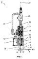
- the device shown for the application of liquid adhesive to a relative to the device in the direction of the arrow shown movable substrate 1 has an applicator head 2.
- the upper part of the applicator head 2 comprises an electro-pneumatically actuable control part 4 (see. Fig. 4 ) mounted on a base 6.
- a nozzle assembly 8 is mounted on the underside of the base 6.
- the base 6 is in turn mounted on a stationary carrier, not shown.
- the control part 4 is connected by means of two compressed air lines 10, 11 to a compressed air source, not shown, which provides approximately a pressure of 6 bar. With the help of a solenoid valve 12, the control part 4 can be acted upon with compressed air.
- the base 6 is formed with a bore 7 into which a lower portion of the control part 4 is inserted.
- In the base 6 are in the upper part of two connecting holes 21, 23, which can be selectively connected to a compressed air line.
- the bore 23 is closed with a plug 25.
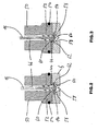
- valve assembly essentially comprises a valve body 14, a rod-shaped shank portion 16 connected thereto, and a valve seat 44.
- the valve body 14 cooperates with the valve seat 44 such that material flow is achieved by movement of the valve body 14 is interrupted in a closed position and released by movement in an open position. The valve body 14 comes into contact with the valve seat by movement against the flow direction of the material to interrupt the flow of material.
- a differential pressure piston 18 is attached to the upper movable shaft portion 16.
- the piston 18 is arranged axially displaceably in a bore 20 in a base body 22.
- the piston 18 is formed with a central bore 20 in which a part of the shaft portion 16 is arranged.
- a nut 24 is screwed, which secures the piston 18 to the shaft portion 16.
- a gas-filled space 26 is provided, which is acted upon by gas pressure. As a result, a force can be applied to the piston 18.
- a further gas-filled space 28 is formed within the bore 20 in the base body 22, which is acted upon by means of a connection channel 30 through the line with compressed air 10.
- the piston 18 has an upper active surface 34, which is larger than a lower active surface 36, so that at the same pressure in the spaces 26 and 30, different forces acting on the piston 18 act.
- the piston would - in Fig. 4 down - are pressed in the direction of the nozzle assembly 8, so that the valve body 14 is pressed into its open position.
- the piston 18 is sealed in a manner not described in detail with O-rings relative to the base body 22.
- a spiral spring 32 is arranged, which acts with its spring force on the piston 18 and this - in Fig. 4 upwards - biased in the closed position of the valve assembly.
- the solenoid valve 12 (FIG. Fig. 1 ) open.
- a pressure is generated in the space 26 which corresponds approximately to that of the compressed air source and which acts on the active surface 34.
- the pressure of the compressed air source prevails throughout.
- the piston 18 is moved in the direction of the substrate 1.
- the solenoid valve 12 is switched so that the pressure in the space 26 is reduced.
- compressed air is discharged from the solenoid valve 12 to the environment.
- the piston 18 is pressed by the force acting on the effective surface 36 resulting force "up” and the valve body 14 is moved to the closed position.
- the spring force of the spring 32 supports.
- the shaft portion 16 of the valve 14 has a notch 38 as a mark, which is visible from the outside through a viewing window 40 in the control part 4, so that the position of the movable, attached to the shaft portion 16 valve body 14 is externally visible.
- an adhesive feed channel 46 is formed in a lower portion of the control member 4 which can be fed by means of a connector 48 with adhesive from an adhesive source ,
- the feed channel 46 is formed substantially as a cylindrical bore within a (ring) body 50.
- a ring 52 is fixed, which is also provided with a central through-hole which is part of the feed channel 46.
- valve seat 44 is formed in the FIGS. 2 and 3 is shown as an annular edge.
- the valve seat 44 may be adapted to the shape of the valve body 14. It can be sanded and hardened.
- O-ring 54 of the ring 52 is realtiv sealed to the base 6.
- the valve body 14 is disposed within a substantially cylindrical space 56 formed in the base 6. The space 56 is followed in the flow direction by a passage 58, can flow through the adhesive into the nozzle assembly 8.
- the integrally formed with the shaft portion 16 valve body 14 is formed as well as the shaft portion 16 rotationally symmetrical and has a subsequent to the shaft portion 16 frusto-conical portion 60 which is in contact with the valve seat 44 in the closed position, as in Fig. 3 is shown.
- the section 60 is followed downstream by a substantially circular disk-shaped portion 62 which further downstream in a turn frusto-conical portion 64 which marks the lower end of the body 14.
- the body 14 initially has a widening cross section, then a constant cross section and further downstream a tapering cross section. It has an outer diameter which is greater than the inner diameter of the feed channel 46, so that upon movement of the shaft portion 16 together with the valve body 14 latter comes to rest on the valve seat 44.
- the diameter of the shaft portion 16 is less than that of the feed channel 46, so that an annular channel is formed between the two.
- valve body 14 may be formed substantially as a ball or disc, which is attached to the shaft portion 16, preferably formed integrally therewith.
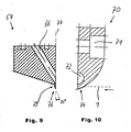
- a passage opens into a channel 66 formed inside the nozzle arrangement 8 which is designed as a slot nozzle arrangement, which channel is formed in an in Fig. 9 illustrated mouthpiece receptacle 68 is formed as a straight through hole.
- the channel 66 is disposed obliquely relative to a vertical axis.
- a mouthpiece 70 mounted separately in Fig. 10 is shown and screwed by means of a bore 71 arranged bolt on the mouthpiece receptacle 68. I'm mounted in Fig.
- FIG. 1 illustrated state opens an elliptical lower opening of the inclined channel 66 in a horizontally disposed in operation distribution channel 72, in which the adhesive is passed into a plurality of outlet channels, not shown, arranged in a conventional manner by means of a between the mouthpiece receptacle 66 and the mouthpiece 70 Spacer plates are formed.
- the outlet channels are formed as elongated slots and open at a lower end of the nozzle assembly 8 (FIG. Fig. 1 ) into slit-shaped outlet openings, from which material can be dispensed.
- the nozzle arrangement 8 has an outer contact area 74, which is in contact with the substrate moving at least in part relative to the outlet opening during the application and which is arranged on the mouthpiece 70.
- the contact region 74 has, as from the Fig. 1 and 10 it can be seen, a relative to the substrate 1 diverging, curved portion. It extends from an exit opening opposite to the direction of movement of the substrate 1 - in Fig. 1 to the left - and is in cross section ( Fig. 10 ) formed part-circular.
- the substrate is flat and lies against the contact region 74, it may however have a slightly curved course, for example if it is designed as a foil guided by rollers.
- the moving substrate 1 is guided from the curved portion of the contact area 74 to the exit opening or the plurality of exit openings of the slot nozzle arrangement arranged in juxtaposition to one another, as in FIG Fig. 10 is indicated by a dashed line. If the outlet opening of the nozzle arrangement during operation is not aligned exactly relative to the substrate 1, for example because the substrate is not guided by a guide device exactly on a desired path or because the entire application head 2 is not exactly located in a desired position on the carrier, then Substrate from the contact portion also guided to the outlet opening.
- the nozzle arrangement 8 has a tear-off edge 76 which is arranged on the mouthpiece receptacle 68.
- the tear-off edge runs an edge 79 of the mouthpiece receptacle 68 in an opposite to an axis 77 (and thus in the Fig. With respect to a vertical axis) acute angle.
- the angle between the edge 79 and the axis 77 is about 20 °.
- FIGS. 5 and 6 show an alternative embodiment of a device according to the invention for applying flowable material, in which two previously described with reference to Fig. 1 to 4 described application heads 78, 80 attached to a base 82 and are arranged substantially perpendicular to each other.
- the device thus has two supply channels which supply a common nozzle arrangement 84 with adhesive.
- the two valve arrangements of the application heads 78 and 80 are controlled electro-pneumatically by means of a control device 77.
- the nozzle assembly 84 has, as previously with reference to FIGS FIGS. 9 and 10 described, a mouthpiece receptacle 86 and attached to this mouthpiece 88.
- the mouthpiece 88 is formed with a curved contact region 74 which at least partially engages a substrate.
- the two valve arrangements of the application heads 78, 80 are controllable such that in a first operating state both valve assemblies release the feed channel 46 for a material flow at the same time and in a second operating state the valve arrangements alternately release or close the respective feed channel 46. In this way, either an alternately intermittent operation of the two guns 78, 80 or a simultaneous flow of material through both guns 78, 80 can be realized. If the two feed channels 46 are fed from different material sources (not shown), during the first operating state the two materials originating from the different material sources can be mixed with one another and applied to a substrate or alternately apply the different materials in the second operating state.
- Fig. 7 shows a part of the application head 78 and the control device 77 and compressed air lines 90, 92, through which the control part for moving the valve body 14 can be acted upon with compressed air.
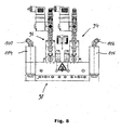
- FIG. 8 Figure 5 shows another alternate embodiment of a flowable material applicator having two guns 94, 96 arranged in parallel and feeding a slot nozzle assembly 98 with material.
- the applicator heads 94, 96 of this device are formed substantially identical, as the basis of the Fig. 1 - 4th described application head 2, and are controllable in the same way as previously with reference to the Fig. 5-7 described device, so that reference is made to the above description.
- By means of two ports 100, 102 and two adhesive filters 104, 106 is adhesive to two terminals 48 in the control part 4 (see. Fig. 4 ).
- the adhesive streams are independent of each other by means of two individually controllable valve arrangements of the applicator heads 94, 96 way described controllable and feed the common slot nozzle assembly 98th
- liquid adhesive or other flowable material by means of supply lines (not shown) in a gun 2, introduced and introduced into the feed channel 46 of a control part 4.
- the material flows into the nozzle assembly 8, there through the obliquely formed in the mouthpiece receiver 68 channel 66 in the substantially horizontal distribution channel 72 in the mouthpiece 70.
- the material is distributed in the distribution channel 72 on a plurality of slot-shaped outlet channels and flows toward the plurality of slit-shaped exit openings at the lower end of the nozzle assembly 8 to be discharged therefrom and applied to the moving substrate 1.
- the substrate may be a thin film of plastic, which is guided by means of several rollers.
- the substrate lies substantially in one plane and is in contact with the contact region 74, more precisely with a part of the curved portion of the contact region 74.
- the nozzle assembly 8 is formed as a slot nozzle arrangement for a flat application, it could also be formed as a nozzle assembly whose outlet openings have other shapes.
- the application heads can be controlled with the aid of the control device 77 such that a continuous or discontinuous intermittent material application is made to the substrate.
- the valve body 14 can be opened or closed up to about 1200 times during one minute.
- the piston 18 In intermittent operation, the piston 18 is acted upon by the lines 10, 11, 90, 92 with compressed air, which can be provided in the spaces 26 and 28 with varying pressures.
- the piston 18 In the open position of the valve body 14, the piston 18 by a force acting in the direction of the substrate 1 downward force in the in Fig. 2 pressed position shown.
- the solenoid valve 12 Fig. 1
- compressed air acts on the piston 18. Since the effective area 34 is greater than the effective area 36, the piston is moved in the direction of the substrate 1.
- the force of the spring 32 acts on the piston 18 on the one hand, and at the same time generates a force in the same direction, the size of which can be calculated essentially as the product of pressure and effective area 36.
- the piston 18 is now moved upwardly together with the shaft portion 16, so that the valve body 14 is moved toward the valve seat 44 until it is in contact with the valve body 44, as in Fig. 3 is shown.
- valve body 14 By the movable arrangement of the valve body 14, this acts within the cylindrical space 56 during the closing movement in the manner of a piston disposed within a cylinder and generates a pressure reduction in the cylindrical space 56. Further adhesive adheres to the surface of the valve body 14, so that the adhering Material together with the opposite to the flow direction of the material during the material application moving valve body 14 is "pulled" up.
- valve assemblies of the two guns can be controlled with the aid of the control device that the valve assemblies alternately enable or close the supply channel for a material flow, so that a job image can be produced on the substrate 1, which has very small gaps between individual application zones and small widths of the application zones depending on a predetermined speed of the substrate 1. This may be desirable, for example, if the integral substrate 1 during the application is to be separated later into several parts, each of which is provided with a defined zone with material application.
- the device can be switched by means of the control device in such a way that both application heads have simultaneously opened valve arrangements, so that material flows through both supply channels is conveyed to the outlet openings (or an outlet opening) and applied. If one of the two valve assemblies is brought into the closed position, in which the material flow is interrupted by the supply channel, while the other valve assembly remains in the open position, as compared to the operating condition in which both valve assemblies are in the open position, a lesser material leakage through the opening (or outlet). If one valve arrangement is operated continuously and the other is operated intermittently, an application pattern can be produced on the substrate 1, which zone has stronger and lower application on the substrate.
Landscapes
- Coating Apparatus (AREA)
Priority Applications (1)
| Application Number | Priority Date | Filing Date | Title |
|---|---|---|---|
| DE29724771U DE29724771U1 (de) | 1996-12-23 | 1997-12-11 | Vorrichtung zum Auftragen von fließfähigem Material auf ein Substrat, insbesondere zum intermittierenden Auftragen von flüssigen Klebstoff |
Applications Claiming Priority (3)
| Application Number | Priority Date | Filing Date | Title |
|---|---|---|---|
| DE29622341U | 1996-12-23 | ||
| DE29622341U DE29622341U1 (de) | 1996-12-23 | 1996-12-23 | Vorrichtung zum Auftragen von fließfähigem Material auf ein Substrat, insbesondere zum intermittierenden Auftragen von flüssigem Klebstoff |
| EP97121817A EP0850697B1 (de) | 1996-12-23 | 1997-12-11 | Vorrichtung zum Auftragen von fliessfähigem Material auf ein Substrat, insbesondere zum intermittierenden Auftragen von flüssigem Klebstoff |
Related Parent Applications (2)
| Application Number | Title | Priority Date | Filing Date |
|---|---|---|---|
| EP97121817A Division EP0850697B1 (de) | 1996-12-23 | 1997-12-11 | Vorrichtung zum Auftragen von fliessfähigem Material auf ein Substrat, insbesondere zum intermittierenden Auftragen von flüssigem Klebstoff |
| EP97121817.7 Division | 1997-12-11 |
Publications (4)
| Publication Number | Publication Date |
|---|---|
| EP1358945A2 EP1358945A2 (de) | 2003-11-05 |
| EP1358945A3 EP1358945A3 (de) | 2004-03-10 |
| EP1358945B1 EP1358945B1 (de) | 2006-01-25 |
| EP1358945B2 true EP1358945B2 (de) | 2011-03-23 |
Family
ID=8033739
Family Applications (2)
| Application Number | Title | Priority Date | Filing Date |
|---|---|---|---|
| EP03017309A Expired - Lifetime EP1358945B2 (de) | 1996-12-23 | 1997-12-11 | Düsenanordnung für eine Vorrichtung zum Auftragen von fliessfähigem Material auf ein Substrat |
| EP97121817A Expired - Lifetime EP0850697B1 (de) | 1996-12-23 | 1997-12-11 | Vorrichtung zum Auftragen von fliessfähigem Material auf ein Substrat, insbesondere zum intermittierenden Auftragen von flüssigem Klebstoff |
Family Applications After (1)
| Application Number | Title | Priority Date | Filing Date |
|---|---|---|---|
| EP97121817A Expired - Lifetime EP0850697B1 (de) | 1996-12-23 | 1997-12-11 | Vorrichtung zum Auftragen von fliessfähigem Material auf ein Substrat, insbesondere zum intermittierenden Auftragen von flüssigem Klebstoff |
Country Status (5)
| Country | Link |
|---|---|
| US (1) | US6164568A (sv) |
| EP (2) | EP1358945B2 (sv) |
| JP (1) | JP3902851B2 (sv) |
| CA (1) | CA2225658A1 (sv) |
| DE (3) | DE29622341U1 (sv) |
Families Citing this family (27)
| Publication number | Priority date | Publication date | Assignee | Title |
|---|---|---|---|---|
| JP3399881B2 (ja) * | 1999-07-29 | 2003-04-21 | 東レエンジニアリング株式会社 | 間欠供給用バルブおよび間欠塗布装置 |
| DE10010952A1 (de) * | 2000-03-06 | 2001-09-27 | Nordson Corp Westlake | Vorrichtung und Verfahren zum intermittierenden Auftragen von fliessfähigem Material |
| US6334554B1 (en) | 2000-04-17 | 2002-01-01 | Illinois Tool Works Inc. | Snuffback valve for hot melt adhesive |
| US6592056B2 (en) * | 2000-07-04 | 2003-07-15 | Konica Corporation | Gluing device, bookbinding apparatus with the gluing device and image forming apparatus with bookbinding apparatus |
| GB2375978B (en) * | 2001-05-29 | 2004-08-04 | C B Kaymich & Company Ltd | Adhesive applicator apparatus |
| US6669057B2 (en) | 2001-10-31 | 2003-12-30 | Nordson Corporation | High-speed liquid dispensing modules |
| US6688580B2 (en) | 2001-10-31 | 2004-02-10 | Nordson Corporation | Adjustable die for a fluid dispenser and method |
| US6673152B2 (en) * | 2001-11-07 | 2004-01-06 | Nordson Corporation | Right angle gluer |
| US7455882B2 (en) | 2004-09-13 | 2008-11-25 | The Gillette Company | Method of applying adhesive to electrochemical cell components |
| DE102004058542A1 (de) * | 2004-12-03 | 2006-06-08 | Nordson Corporation, Westlake | Rotationsauftragskopf und Etikettieranlage zum Aufbringen von Etiketten |
| US7771556B2 (en) | 2005-07-01 | 2010-08-10 | Nordson Corporation | Apparatus and process to apply adhesive during labeling operations |
| US8474660B2 (en) * | 2006-11-15 | 2013-07-02 | Nordson Corporation | Dispensing apparatus having a pivot actuator |
| US8061564B2 (en) * | 2006-11-15 | 2011-11-22 | Nordson Corporation | Liquid dispensing apparatus including an attachment member |
| US8256374B2 (en) * | 2007-04-11 | 2012-09-04 | Nordson Corporation | Apparatus and methods for profile wrapping laminates |
| DE102008018881B4 (de) * | 2008-03-11 | 2020-10-01 | Atlas Copco Ias Gmbh | Verfahren und Vorrichtung zum Auftragen eines viskosen Materials auf ein Werkstück sowie Verwendung eines Nadelventils für eine Vorrichtung zum Auftragen eines viskosen Materials auf ein Werkstück |
| EP2480492B1 (en) * | 2009-09-21 | 2019-11-06 | Nordson Corporation | Pneumatically actuated liquid dispensing valve |
| US9346075B2 (en) | 2011-08-26 | 2016-05-24 | Nordson Corporation | Modular jetting devices |
| US8708246B2 (en) | 2011-10-28 | 2014-04-29 | Nordson Corporation | Positive displacement dispenser and method for dispensing discrete amounts of liquid |
| DE202011107265U1 (de) | 2011-10-31 | 2013-02-11 | Nordson Corporation | Abgabemodul, Auftragskopf und Düsenstock zur Abgabe eines Fluids, insbesondere Heißschmelzklebstoff |
| CN104096659A (zh) * | 2014-07-17 | 2014-10-15 | 苏州博众精工科技有限公司 | 一种点胶机构 |
| US10124303B2 (en) | 2014-09-05 | 2018-11-13 | Nordson Corporation | Apparatus and methods for dispensing small beads of viscous material |
| US9889599B2 (en) * | 2015-09-15 | 2018-02-13 | Illinois Tool Works Inc. | Multi-temperature contact applicator |
| JP6452850B2 (ja) | 2016-08-16 | 2019-01-16 | 株式会社サンツール | サックバック式塗布ガンユニット |
| DE102016118694A1 (de) * | 2016-10-02 | 2018-04-05 | Ba Assembly & Turnkey Systems Gmbh | Vorrichtung zum Auftrag eines viskosen Materials |
| JP6452851B2 (ja) * | 2016-12-23 | 2019-01-16 | 株式会社サンツール | サックバック式間欠塗布システム。 |
| DE102018101801A1 (de) * | 2018-01-26 | 2019-08-01 | Scheugenpflug Ag | Verfahren zum flächigen, lückenlosen Auftragen eines viskosen Substrates auf einer Platte |
| BR112023004357A2 (pt) * | 2020-09-09 | 2023-04-04 | Spraying Systems Co | Conjunto de bico de pulverização de distribuição de líquido |
Citations (1)
| Publication number | Priority date | Publication date | Assignee | Title |
|---|---|---|---|---|
| EP0945757B1 (en) † | 1992-10-20 | 2005-04-20 | Fuji Photo Film Co., Ltd. | Coating apparatus |
Family Cites Families (26)
| Publication number | Priority date | Publication date | Assignee | Title |
|---|---|---|---|---|
| US2766484A (en) * | 1951-10-24 | 1956-10-16 | Mccorquodale Colour Display | Apparatus for use in depositing fluid or viscous materials on surfaces |
| US3854631A (en) * | 1973-05-04 | 1974-12-17 | L Moen | Automatic dispenser for hot fluids under pressure |
| US4484711A (en) * | 1981-04-27 | 1984-11-27 | Spiridon Constantinescu | Shower head adapted to stop and to allow the flow of mixed water |
| AT376175B (de) * | 1982-10-07 | 1984-10-25 | Johannes Zimmer | Vorrichtung zum gleichmaessigen auftragen von fliessfaehigen medien |
| IT1180523B (it) * | 1984-08-22 | 1987-09-23 | Gd Spa | Valvola per l'erogazione di liquidi in particolare colla |
| US4678100A (en) * | 1985-06-17 | 1987-07-07 | Loctite Corporation | Variable flow rate dispensing valve assembly |
| US4667879A (en) * | 1985-08-21 | 1987-05-26 | Nordson Corporation | Thermoplastic material applicator having an adjustable slot nozzle |
| US4687137A (en) * | 1986-03-20 | 1987-08-18 | Nordson Corporation | Continuous/intermittent adhesive dispensing apparatus |
| JPS63143931A (ja) * | 1986-12-08 | 1988-06-16 | Nordson Kk | 液体の混合比率の設定調整方法とその装置 |
| DE3804856A1 (de) * | 1988-02-17 | 1989-08-31 | Macon Gmbh Klebstoff Auftragsg | Vorrichtung zum flaechigen auftragen von leim oder dergleichen |
| EP0329813A1 (de) * | 1988-02-26 | 1989-08-30 | Nordson Corporation | Ventilanordnung zum intermittierenden Auftragen eines flüssigen Klebstoffes auf ein Substrat |
| GB2219627B (en) * | 1988-06-10 | 1992-10-28 | Orbital Eng Pty | Improvements relating to nozzles for in-cylinder fuel injection systems |
| US5094399A (en) * | 1988-09-26 | 1992-03-10 | Technadyne Engineering Corporation | Application of thermal-cure materials |
| DE8812493U1 (sv) * | 1988-10-04 | 1990-02-01 | Claassen, Henning J., 2120 Lueneburg, De | |
| JPH0426065U (sv) * | 1990-06-20 | 1992-03-02 | ||
| US5022358A (en) * | 1990-07-24 | 1991-06-11 | North American Philips Corporation | Low energy hydraulic actuator |
| DE4117999A1 (de) * | 1991-06-01 | 1992-12-03 | Erno Raumfahrttechnik Gmbh | Vorrichtung zur steuerung eines fluessigkeitsstromes |
| DE4211942C2 (de) * | 1992-04-09 | 1995-09-07 | Wallner Harald | Klebstoffauftragventil |
| US5277342A (en) * | 1992-12-11 | 1994-01-11 | Loctite Corporation | Sealless dispensing apparatus |
| DE4304068A1 (de) * | 1993-02-11 | 1994-08-18 | Peter Swoboda | Einspritzventil |
| JP3565574B2 (ja) * | 1993-12-27 | 2004-09-15 | 松下電器産業株式会社 | 粘性体塗布装置 |
| US5499745A (en) * | 1994-02-18 | 1996-03-19 | Nordson Corporation | Apparatus for mixing and dispensing two chemically reactive materials |
| FR2717107B1 (fr) * | 1994-03-11 | 1996-04-26 | Renault | Installation et procédé pour la distribution simultanée de plusieurs doses ponctuelles de volume déterminé d'un produit pâteux. |
| IT233246Y1 (it) * | 1994-04-13 | 2000-01-26 | Sagitta Off Mec | Dispositivo di erogazione continua di sostanze dense e/o vischiose con asta cilindrica coassialmente scorrevole |
| DE4447016A1 (de) * | 1994-12-30 | 1996-07-11 | Focke & Co | Düsenaggregat zum Auftragen von Leim |
| DE29613761U1 (de) * | 1996-08-09 | 1996-12-05 | Lenhardt Maschinenbau | Vorrichtung zum Auftragen eines plastischen Abstandhalters auf eine Glastafel |
-
1996
- 1996-12-23 DE DE29622341U patent/DE29622341U1/de not_active Expired - Lifetime
-
1997
- 1997-12-11 DE DE59712557T patent/DE59712557D1/de not_active Expired - Lifetime
- 1997-12-11 DE DE59711829T patent/DE59711829D1/de not_active Expired - Lifetime
- 1997-12-11 EP EP03017309A patent/EP1358945B2/de not_active Expired - Lifetime
- 1997-12-11 EP EP97121817A patent/EP0850697B1/de not_active Expired - Lifetime
- 1997-12-22 US US08/996,390 patent/US6164568A/en not_active Expired - Lifetime
- 1997-12-23 CA CA002225658A patent/CA2225658A1/en not_active Abandoned
- 1997-12-24 JP JP35464197A patent/JP3902851B2/ja not_active Expired - Fee Related
Patent Citations (1)
| Publication number | Priority date | Publication date | Assignee | Title |
|---|---|---|---|---|
| EP0945757B1 (en) † | 1992-10-20 | 2005-04-20 | Fuji Photo Film Co., Ltd. | Coating apparatus |
Also Published As
| Publication number | Publication date |
|---|---|
| DE29622341U1 (de) | 1997-04-03 |
| EP0850697A3 (de) | 1999-07-21 |
| EP1358945A2 (de) | 2003-11-05 |
| EP0850697B1 (de) | 2004-08-04 |
| JP3902851B2 (ja) | 2007-04-11 |
| DE59711829D1 (de) | 2004-09-09 |
| JPH10192763A (ja) | 1998-07-28 |
| EP1358945A3 (de) | 2004-03-10 |
| US6164568A (en) | 2000-12-26 |
| DE59712557D1 (de) | 2006-04-13 |
| EP0850697A2 (de) | 1998-07-01 |
| CA2225658A1 (en) | 1998-06-23 |
| EP1358945B1 (de) | 2006-01-25 |
Similar Documents
| Publication | Publication Date | Title |
|---|---|---|
| EP1358945B2 (de) | Düsenanordnung für eine Vorrichtung zum Auftragen von fliessfähigem Material auf ein Substrat | |
| DE3721593C2 (sv) | ||
| DE19714029C2 (de) | Auftragskopf | |
| DE69635817T2 (de) | Modul mit verminderter Öffnung und auswechselbarem Sitz | |
| EP1181105B1 (de) | Vorrichtung zum auftragen von fluid | |
| DE19882393B4 (de) | Beschichtungsvorrichtung | |
| DE2100771A1 (de) | Gerät zum Auftragen von Fluiden | |
| DE60117431T2 (de) | Klebstoffdüse mit einem geteilten Auslass | |
| DE19807973C1 (de) | Spritzvorrichtung zum Zerstäuben von Flüssigkeiten | |
| EP2145695A1 (de) | Vorrichtung zur Klebstoffapplikation | |
| DE202006014743U1 (de) | Vorrichtung zum Auftragen von Fluiden wie Klebstoff, insbesondere Schmelzkleber | |
| EP1352691A2 (de) | Rotationskopf mit Verschlussleisten | |
| EP0224916A1 (de) | Vorrichtung zum intermittierenden Auftragen von flüssigem Klebstoff | |
| DE102014010843B4 (de) | Dosierdüse und Verfahren zum dosierten Auftragen hochviskoser Medien | |
| DE102008006205A1 (de) | Florstreichvorrichtung für eine Papier-/Kartonbahn | |
| EP0406529B1 (de) | Streicheinrichtung | |
| DE202006019724U1 (de) | Vorrichtung mit Schlitzdüsenanordnung zum Abgeben von Fluid | |
| EP0366962B1 (de) | Schlitzdüse | |
| DE2145131C3 (de) | Vorrichtung zum gleichmäßigen und stufenlos veränderbaren Einölen von kontinuierlich bewegtem Walzgut, insbesondere von Blechbändern oder -tafeln | |
| DE29724771U1 (de) | Vorrichtung zum Auftragen von fließfähigem Material auf ein Substrat, insbesondere zum intermittierenden Auftragen von flüssigen Klebstoff | |
| DE19949100B4 (de) | Druckkammerrakel zum Auftragen eines Mediums auf eine Walze | |
| EP1070551B1 (de) | Vorrichtung zur dosierten Abgabe von strömenden Medien | |
| EP1383613A1 (de) | Vorrichtung und verfahren zum abgeben von fluid auf ein relativ zu der vorrichtung bewegbares substrat | |
| EP0732152A1 (de) | Vorrichtung zum Auftragen von flüssigen Medien | |
| EP0274082A2 (de) | Spritzvorrichtung für Beregnungsanlagen |
Legal Events
| Date | Code | Title | Description |
|---|---|---|---|
| PUAI | Public reference made under article 153(3) epc to a published international application that has entered the european phase |
Free format text: ORIGINAL CODE: 0009012 |
|
| AC | Divisional application: reference to earlier application |
Ref document number: 0850697 Country of ref document: EP Kind code of ref document: P |
|
| AK | Designated contracting states |
Kind code of ref document: A2 Designated state(s): CH DE ES FR GB IT LI |
|
| PUAL | Search report despatched |
Free format text: ORIGINAL CODE: 0009013 |
|
| RIN1 | Information on inventor provided before grant (corrected) |
Inventor name: HERING, ERNST Inventor name: BURMESTER, GUNTHER Inventor name: KUFNER, HUBERT Inventor name: GRUMMT, ANDREW Inventor name: BURMESTER, THOMAS Inventor name: SEEDORF, HANS-JOACHIM Inventor name: BORNKESSEL, ANDREAS Inventor name: MUELLER, MANFRED Inventor name: LOHSE, DONALD |
|
| AK | Designated contracting states |
Kind code of ref document: A3 Designated state(s): CH DE ES FR GB IT LI |
|
| RIC1 | Information provided on ipc code assigned before grant |
Ipc: 7B 05C 11/10 B Ipc: 7B 05C 5/02 A |
|
| 17P | Request for examination filed |
Effective date: 20040910 |
|
| AKX | Designation fees paid |
Designated state(s): DE GB |
|
| GRAP | Despatch of communication of intention to grant a patent |
Free format text: ORIGINAL CODE: EPIDOSNIGR1 |
|
| RTI1 | Title (correction) |
Free format text: NOZZLE ARRANGEMENT FOR A DEVICE FOR APPLYING A FLOWABLE MATERIAL ONTO A SUBSTRATE |
|
| GRAS | Grant fee paid |
Free format text: ORIGINAL CODE: EPIDOSNIGR3 |
|
| GRAA | (expected) grant |
Free format text: ORIGINAL CODE: 0009210 |
|
| AC | Divisional application: reference to earlier application |
Ref document number: 0850697 Country of ref document: EP Kind code of ref document: P |
|
| AK | Designated contracting states |
Kind code of ref document: B1 Designated state(s): DE GB |
|
| REG | Reference to a national code |
Ref country code: GB Ref legal event code: FG4D Free format text: NOT ENGLISH |
|
| REF | Corresponds to: |
Ref document number: 59712557 Country of ref document: DE Date of ref document: 20060413 Kind code of ref document: P |
|
| GBT | Gb: translation of ep patent filed (gb section 77(6)(a)/1977) |
Effective date: 20060503 |
|
| PLBI | Opposition filed |
Free format text: ORIGINAL CODE: 0009260 |
|
| PLAX | Notice of opposition and request to file observation + time limit sent |
Free format text: ORIGINAL CODE: EPIDOSNOBS2 |
|
| 26 | Opposition filed |
Opponent name: APRO TECHNOLOGIE GMBH Effective date: 20061024 Opponent name: ITW DYNATEC GMBH Effective date: 20061025 |
|
| PGFP | Annual fee paid to national office [announced via postgrant information from national office to epo] |
Ref country code: GB Payment date: 20061221 Year of fee payment: 10 |
|
| PLAF | Information modified related to communication of a notice of opposition and request to file observations + time limit |
Free format text: ORIGINAL CODE: EPIDOSCOBS2 |
|
| PLAF | Information modified related to communication of a notice of opposition and request to file observations + time limit |
Free format text: ORIGINAL CODE: EPIDOSCOBS2 |
|
| PLBB | Reply of patent proprietor to notice(s) of opposition received |
Free format text: ORIGINAL CODE: EPIDOSNOBS3 |
|
| PLBP | Opposition withdrawn |
Free format text: ORIGINAL CODE: 0009264 |
|
| GBPC | Gb: european patent ceased through non-payment of renewal fee |
Effective date: 20071211 |
|
| PLAB | Opposition data, opponent's data or that of the opponent's representative modified |
Free format text: ORIGINAL CODE: 0009299OPPO |
|
| PG25 | Lapsed in a contracting state [announced via postgrant information from national office to epo] |
Ref country code: GB Free format text: LAPSE BECAUSE OF NON-PAYMENT OF DUE FEES Effective date: 20071211 |
|
| APBM | Appeal reference recorded |
Free format text: ORIGINAL CODE: EPIDOSNREFNO |
|
| APBP | Date of receipt of notice of appeal recorded |
Free format text: ORIGINAL CODE: EPIDOSNNOA2O |
|
| APAH | Appeal reference modified |
Free format text: ORIGINAL CODE: EPIDOSCREFNO |
|
| PLAB | Opposition data, opponent's data or that of the opponent's representative modified |
Free format text: ORIGINAL CODE: 0009299OPPO |
|
| APBQ | Date of receipt of statement of grounds of appeal recorded |
Free format text: ORIGINAL CODE: EPIDOSNNOA3O |
|
| PLAB | Opposition data, opponent's data or that of the opponent's representative modified |
Free format text: ORIGINAL CODE: 0009299OPPO |
|
| R26 | Opposition filed (corrected) |
Opponent name: APRO TECHNOLOGIE GMBH Effective date: 20061024 |
|
| APBU | Appeal procedure closed |
Free format text: ORIGINAL CODE: EPIDOSNNOA9O |
|
| PUAH | Patent maintained in amended form |
Free format text: ORIGINAL CODE: 0009272 |
|
| STAA | Information on the status of an ep patent application or granted ep patent |
Free format text: STATUS: PATENT MAINTAINED AS AMENDED |
|
| 27A | Patent maintained in amended form |
Effective date: 20110323 |
|
| AK | Designated contracting states |
Kind code of ref document: B2 Designated state(s): DE GB |
|
| REG | Reference to a national code |
Ref country code: DE Ref legal event code: R102 Ref document number: 59712557 Country of ref document: DE Effective date: 20110323 |
|
| PGFP | Annual fee paid to national office [announced via postgrant information from national office to epo] |
Ref country code: DE Payment date: 20141211 Year of fee payment: 18 |
|
| REG | Reference to a national code |
Ref country code: DE Ref legal event code: R119 Ref document number: 59712557 Country of ref document: DE |
|
| PG25 | Lapsed in a contracting state [announced via postgrant information from national office to epo] |
Ref country code: DE Free format text: LAPSE BECAUSE OF NON-PAYMENT OF DUE FEES Effective date: 20160701 |