EP1356903A1 - Schneidkopf für Schneideinrichtungen zum Schneiden von Gipskartonplatten und plattenförmigen Bauelementen aus ähnlichen Materialien - Google Patents
Schneidkopf für Schneideinrichtungen zum Schneiden von Gipskartonplatten und plattenförmigen Bauelementen aus ähnlichen Materialien Download PDFInfo
- Publication number
- EP1356903A1 EP1356903A1 EP03009112A EP03009112A EP1356903A1 EP 1356903 A1 EP1356903 A1 EP 1356903A1 EP 03009112 A EP03009112 A EP 03009112A EP 03009112 A EP03009112 A EP 03009112A EP 1356903 A1 EP1356903 A1 EP 1356903A1
- Authority
- EP
- European Patent Office
- Prior art keywords
- cutting
- cutting head
- wheel
- plate
- head according
- Prior art date
- Legal status (The legal status is an assumption and is not a legal conclusion. Google has not performed a legal analysis and makes no representation as to the accuracy of the status listed.)
- Granted
Links
- 238000005520 cutting process Methods 0.000 title claims abstract description 104
- 239000000463 material Substances 0.000 title claims description 8
- 229910052602 gypsum Inorganic materials 0.000 title description 4
- 239000010440 gypsum Substances 0.000 title description 4
- 239000011505 plaster Substances 0.000 title 1
- 238000000926 separation method Methods 0.000 claims description 5
- 238000007654 immersion Methods 0.000 claims description 3
- 230000005540 biological transmission Effects 0.000 claims description 2
- 238000005096 rolling process Methods 0.000 claims description 2
- 239000000428 dust Substances 0.000 description 6
- 238000004519 manufacturing process Methods 0.000 description 6
- 239000004566 building material Substances 0.000 description 5
- 238000003754 machining Methods 0.000 description 4
- 238000000034 method Methods 0.000 description 3
- 239000000945 filler Substances 0.000 description 2
- 238000009434 installation Methods 0.000 description 2
- 238000005192 partition Methods 0.000 description 2
- 238000010276 construction Methods 0.000 description 1
- 230000006698 induction Effects 0.000 description 1
- 238000003475 lamination Methods 0.000 description 1
- 238000003801 milling Methods 0.000 description 1
- 238000009418 renovation Methods 0.000 description 1
- 239000002699 waste material Substances 0.000 description 1
- XLYOFNOQVPJJNP-UHFFFAOYSA-N water Substances O XLYOFNOQVPJJNP-UHFFFAOYSA-N 0.000 description 1
- 239000002023 wood Substances 0.000 description 1
Images

Classifications
-
- B—PERFORMING OPERATIONS; TRANSPORTING
- B28—WORKING CEMENT, CLAY, OR STONE
- B28D—WORKING STONE OR STONE-LIKE MATERIALS
- B28D1/00—Working stone or stone-like materials, e.g. brick, concrete or glass, not provided for elsewhere; Machines, devices, tools therefor
- B28D1/22—Working stone or stone-like materials, e.g. brick, concrete or glass, not provided for elsewhere; Machines, devices, tools therefor by cutting, e.g. incising
- B28D1/24—Working stone or stone-like materials, e.g. brick, concrete or glass, not provided for elsewhere; Machines, devices, tools therefor by cutting, e.g. incising with cutting discs
-
- B—PERFORMING OPERATIONS; TRANSPORTING
- B26—HAND CUTTING TOOLS; CUTTING; SEVERING
- B26B—HAND-HELD CUTTING TOOLS NOT OTHERWISE PROVIDED FOR
- B26B25/00—Hand cutting tools involving disc blades, e.g. motor-driven
-
- B—PERFORMING OPERATIONS; TRANSPORTING
- B26—HAND CUTTING TOOLS; CUTTING; SEVERING
- B26D—CUTTING; DETAILS COMMON TO MACHINES FOR PERFORATING, PUNCHING, CUTTING-OUT, STAMPING-OUT OR SEVERING
- B26D1/00—Cutting through work characterised by the nature or movement of the cutting member or particular materials not otherwise provided for; Apparatus or machines therefor; Cutting members therefor
- B26D1/01—Cutting through work characterised by the nature or movement of the cutting member or particular materials not otherwise provided for; Apparatus or machines therefor; Cutting members therefor involving a cutting member which does not travel with the work
- B26D1/12—Cutting through work characterised by the nature or movement of the cutting member or particular materials not otherwise provided for; Apparatus or machines therefor; Cutting members therefor involving a cutting member which does not travel with the work having a cutting member moving about an axis
- B26D1/14—Cutting through work characterised by the nature or movement of the cutting member or particular materials not otherwise provided for; Apparatus or machines therefor; Cutting members therefor involving a cutting member which does not travel with the work having a cutting member moving about an axis with a circular cutting member, e.g. disc cutter
- B26D1/24—Cutting through work characterised by the nature or movement of the cutting member or particular materials not otherwise provided for; Apparatus or machines therefor; Cutting members therefor involving a cutting member which does not travel with the work having a cutting member moving about an axis with a circular cutting member, e.g. disc cutter coacting with another disc cutter
-
- B—PERFORMING OPERATIONS; TRANSPORTING
- B26—HAND CUTTING TOOLS; CUTTING; SEVERING
- B26D—CUTTING; DETAILS COMMON TO MACHINES FOR PERFORATING, PUNCHING, CUTTING-OUT, STAMPING-OUT OR SEVERING
- B26D3/00—Cutting work characterised by the nature of the cut made; Apparatus therefor
- B26D3/06—Grooving involving removal of material from the surface of the work
Definitions
- the invention relates to a cutting head, which in Devices for processing, primarily the cutting of Plasterboard, plasterboard, wood-based panels or the like, can be used.
- the cut is made before processing on site such building material panels to the desired dimensions.
- Two techniques are used primarily. These are used to produce linear separations Components positioned horizontally.
- the plates are then turned over and the underside of the separating layer is cut through. This method is known from DE 19937140 and US 2952025. Subsequently, the building material panels are provided with a spatula if necessary, which is produced manually using an edge planer.
- plates for use in Construction area can be cut using a water jet.
- this cutting is not with plasterboard can be used because the plate material is characterized by the would dissolve moisture.
- DE 3044467 which is a Hand cutter with wallpaper blades for cutting suggests.
- the document DE 195 12 403 A1 describes a device for cutting plasterboard on both sides, which consists of a cutting head which has cutting wheels engaging in the surface.
- the disadvantage of this solution is the fact that with different material thicknesses and when the scoring knives acting on both sides wear out, the cutting heads need to be adjusted or readjusted. Furthermore, this solution always requires two opposing cutting tools and only the cardboard layers on the top and bottom of the board are severed so that the board must then be broken.
- JP 05154832 A which on the top and on the bottom two each Has pairs of cutting wheels, which overlaps the Cut through material.
- the disadvantage of this Device that propulsion driven by Cutting wheels or by roller transport, which is only allows low cutting performance.
- DD 47327 Also known from DD 47327 is a device which creates scratches on the top and bottom of the workpiece.
- the feed is realized by driven cutting / scoring wheels, which are arranged on both sides in an axis to each other.
- the function of the abutment for absorbing the cutting forces is taken over by the opposing cutting wheels. It is again disadvantageous that only the top and bottom of the plate are scratched, so that the plate then has to be broken.
- the invention accordingly has the task of a To provide solution that has the disadvantages mentioned largely avoids the machining process during generation mechanized with high accuracy and edge quality, reduces dust pollution and a significant increase the working speed.
- Figure 1 shows the cutting head according to the invention, which consists of a basic body on which a front print wheel 2, a front drive wheel 3, a Cutting wheel 5, an abutment 6, a rear pressure wheel 7 and a rear drive wheel 8 are arranged.
- the front printing wheel 2 is arranged so that it is on the top of the plate 1 runs.
- the front one runs parallel to the front printing wheel 2 Drive wheel 3 on the underside of the plate 1 to the front print wheel 2.
- a cutting wheel 5 engaging in the surface of the plate 1 is arranged in the cutting direction behind the front drive wheel 3. This cutting wheel 5 is dimensioned such that it penetrates the plate 1 with its cutting edge to such an extent that the plate parts are completely separated.
- This abutment preferably runs parallel to the axis Cutting wheel 5 and is in a special embodiment provided a gap into which the cutting knife 5, which preferably as a rolling knife with a circumferential cutting edge a maximum thickness of 1.5 mm and in one Cutting edge angle ⁇ is less than 30 °, plunges, this immersion gap by max. 20% wider than that Cutting knife is.
- the entire cutting head has on its rear side in the cutting direction a pair of rear pressure wheel 7 and rear drive wheel 8, which corresponds in position to one another to the pairing of front pressure wheel 2 and front drive wheel 3.
- the inventive design of the cutting head enables all machining operations to be carried out on one side, preferably the top of the building material panel.
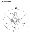
- Figure 2 shows one in a special design arranged bevel cutting head 9, which for generating the Spatula is used.
- This bevel cutting head 9 is preferably arranged to be connectable in the cutting direction between the front printing wheel 2 and the cutting wheel 5.
- the bevel cutting head 9 consists of two bevel wheels 4 arranged symmetrically and transversely to the cutting axis and in the cutting angle ⁇ to be produced. These chamfer wheels 4 are adjustable with respect to one another at a cutting angle ⁇ and incline toward the plate 1 to be machined.
- the bevel and the diameter of the bevel wheels 4 define the bevel to be introduced into the plate in terms of its width and depth
- the bevel wheels 4 are designed as roller knives with a circumferential cutting edge in such a way that these bevel wheels 4 have an angle ⁇ a of 90 ° with respect to their axis 10 with respect to their axis 10.
- the base body of the cutting head consists of two fork-shaped spars arranged parallel to one another, between which the upper part and the lower part of the cutting head are arranged and guided.
- the pressure and drive wheels are guided in such a way that the contact pressure required for the cutting process is generated for the pressure and drive wheels.
- the cutting head is preferably driven by an electric gear motor.
- the rear drive wheel 8 is preferably driven via a drive shaft and a clutch.
- the rear drive wheel 8 is preferably connected to the front drive wheel 3 by means of a toothed belt, so that both drive wheels realize a uniform feed.
- the cutting head is placed on the plate 1 to be cut so that the front drive wheel 3 and the front pressure wheel 2 are on the plate 1 and the feed through the front drive wheel 3 pulls the cutting head onto the plate 1.
- the optional bevel cutting head 9 is immersed with the bevel wheels 4 and the later filler bevel is cut.
- the subsequent cutting wheel 5 separates the material at the deepest point of the spatula introduced, whereby it dips into the abutment 6 and is guided laterally by the latter.
- the bevel cutting head 9 is not installed, the The plate is only cut through by the cutting wheel 5.
- the rear pressure wheel 7 and the rear drive wheel 8 move on the table in such a way that both drive wheels 3 and 8 induce the feed of the cutting head during the main cutting movement.
- the rear drive wheel 8 takes over the induction of the feed force alone.
- the device according to the invention advantageously enables the production of the filler bevel and the precise separation of the plasterboard in one operation. Almost no dust is produced even at high cutting speeds.
Landscapes
- Engineering & Computer Science (AREA)
- Mechanical Engineering (AREA)
- Life Sciences & Earth Sciences (AREA)
- Forests & Forestry (AREA)
- Mining & Mineral Resources (AREA)
- Processing Of Stones Or Stones Resemblance Materials (AREA)
- Knives (AREA)
- Magnetic Heads (AREA)
- Devices For Post-Treatments, Processing, Supply, Discharge, And Other Processes (AREA)
Abstract
Description
Bekannt ist dies Verfahren aus der DE 19937140 und der US 2952025.
Im Anschluss daran werden die Baustoffplatten bei Notwendigkeit mit einer Spachtelfase versehen, die mittels eines Kantenhobels manuell hergestellt wird.
Nachteilig wirkt sich bei dieser Lösung die Tatsache aus, dass bei unterschiedlichen Materialstärken und bei Abnutzung der beidseitig wirkenden Ritzmesser ein Ein- bzw. Nachstellen der Schneidköpfe erforderlich ist. Desweiteren werden bei dieser Lösung immer zwei sich gegenüberstehende Schneidwerkzeuge benötigt und es werden lediglich die Kartonschichten auf der Plattenober- und Unterseite durchtrennt, so daß die Platte anschließend gebrochen werden muss.
Der Vorschub wird durch angetriebene Schneid-/ Ritzrädchen realisiert, die beidseitig in Achse zueinander angeordnet sind.
Die Funktion des Widerlagers zum Aufnehmen der Schneidkräfte wird gemäß dieser technischen Lösung durch die sich gegenüber liegenden Schneidräder übernommen.
Nachteilig ist wiederum, daß lediglich die Plattenober- und Unterseite geritzt werden, so daß die Platte anschließend gebrochen werden muss.
Dieses Schneidrad 5 ist dabei so dimensioniert, daß es mit seiner Schneidkante die Platte 1 soweit durchdringt, daß eine vollständige Trennung der Plattenteile erfolgt.
Der erfindungsgemäße Schneidkopf ermöglicht durch seine erfindungsgemäße konstruktive Gestaltung, dass sämtliche Bearbeitungsvorgänge auf einer Seite, vorzugsweise der Oberseite der Baustoffplatte, erfolgen.
Der Fasenschneidkopf 9 besteht aus zwei quer zur Schneidachse symmetrisch und im zu produzierenden Schneidwinkel α angeordnete Fasenrädern 4.
Diese Fasenräder 4 sind in einem Schneidwinkel α einstellbar zueinander und zu der zu bearbeitenden Platte 1 zu neigen. Mittels der Neigung und des Durchmessers der Fasenräder 4 wird die in die Platte einzubringende Fase in ihrer Breite und Tiefe definiert
Dabei erfolgt die Führung der Druck- und Antriebsräder so, dass die für den Schneidvorgang notwendige Anpresskraft für die Druck- und Antriebsräder erzeugt wird.
Mittels dieses Elektrogetriebemotors wird vorzugsweise über eine Antriebswelle und eine Kupplung das hintere Antriebsrad 8 angetrieben.
Zur weiteren Kraftübertragung ist das hintere Antriebsrad 8 vorzugsweise mittels eines Zahnriemens mit dem vorderen Antriebsrad 3 verbunden, so dass beide Antriebsräder einen gleichmäßigen Vorschub realisieren.
Beim Beginn des Schneidvorganges wird der Schneidkopf so auf die zu schneidende Platte 1 aufgesetzt, dass sich das vordere Antriebsrad 3 und das vordere Druckrad 2 auf der Platte 1 befinden und der Vorschub durch das vordere Antriebsrad 3 den Schneidkopf auf die Platte 1 zieht.
Dabei taucht der optionale Fasenschneidkopf 9 mit den Fasenrädern 4 ein und es wird die spätere Spachtelfase geschnitten.
Das nachfolgende Schneidrad 5 trennt das Material an der tiefsten Stelle der eingebrachten Spachtelfase, wobei es in das Widerlager 6 eintaucht und von diesem seitlich geführt wird.
Beim Austauchen der Schneideinrichtung aus der geschnittenen Platte 1 übernimmt das hintere Antriebsrad 8 die Induzierung der Vorschubkraft allein.
Dabei wird selbst bei hohen Schnittgeschwindigkeiten nahezu kein Staub produziert.
Claims (11)
- Schneidkopf für Schneideinrichtungen zum Schneiden von Gipskartonplatten und plattenförmigen Bauelementen aus ähnlichen Materialien, bestehend aus einem Schneidkopf, welcher aus einem Grundkörper besteht, an welchem ein vorderes Druckrad (2), ein vorderes Antriebsrad (3), ein Schneidrad (5), ein Widerlager (6), ein hinteres Druckrad (7) sowie ein hinteres Antriebsrad (8) angeordnet sind, wobei das vordere Druckrad (2) so angeordnet ist, daß es auf der Oberseite der Platte (1) und achsparallel zu dem auf der Unterseite der Platte (1) laufenden vorderen Antriebsrad (3) läuft, daß in Schneidrichtung hinter dem vorderen Druckrad (2) ein in die Oberfläche der Platte (1) eingreifendes Schneidrad (5) angeordnet ist, welches so dimensioniert ist, daß es mit seiner Schneidkante die Platte (1) soweit durchdringt, daß eine vollständige Trennung der Plattenteile erfolgt, daß unterhalb der Platte (1) ein Widerlager (6) angeordnet ist und daß in Schneidrichtung hinter dem Schneidrad (5) eine Paarung aus hinterem Druckrad (7) und hinterem Antriebsrad (8) angeordnet ist, welches in seiner Lage zueinander der Paarung aus vorderem Druckrad (2) und vorderem Antriebsrad (3) entspricht.
- Schneidkopf nach Anspruch 1, dadurch gekennzeichnet, daß das Schneidmesser (5) ein Rollmesser mit umlaufender Schneide mit einer maximalen Dicke von 1,5 mm und in einem Schneidenwinkel ε kleiner 30°augestaltet ist.
- Schneidkopf nach Anspruch 1, dadurch gekennzeichnet, daß das Widerlager (6) eine Rolle ist, welche achsparallel zu dem Schneidrad (5) angeordnet ist und welche mit einem Eintauchspalt für des Schneidmesser (5) versehen ist.
- Schneidkopf nach Anspruch 3, dadurch gekennzeichnet, daß der Eintauchspalt um max. 20 % breiter als das Schneidmesser ist.
- Schneidkopf nach Anspruch 1, dadurch gekennzeichnet, daß zur Erzeugung der Spachtelfase vor dem Schneidmesser (5) ein vorweglaufender, zuschaltbarer Fasenschneidkopf (9) angeordnet ist.
- Schneidkopf nach Anspruch 5, dadurch gekennzeichnet, daß der Fasenschneidkopf (9) zwei quer zur Schneidachse symmetrisch und im zu produzierenden Schneidwinkel α angeordnete Fasenräder (4) aufweist.
- Schneidkopf nach Anspruch 6, dadurch gekennzeichnet, daß die Fasenräder (4) in einem Schneidwinkel α einstellbar zueinander und zu der zu bearbeitenden Platte (1) zu neigen sind.
- Schneidkopf nach Anspruch 6, dadurch gekennzeichnet, daß die Fasenräder (4) Rollmesser mit umlaufender Schneide sind und daß diese Messer zur Außenseite der Spachtelfase, bezogen auf ihre Achse 10 einen Schneidenwinkel βa von 90° aufweisen.
- Schneidkopf nach Anspruch 1, dadurch gekennzeichnet, daß der Grundkörper des Schneidkopfes aus zwei gabelförmig parallel zueinander angeordneten Holmen, zwischen welchen das Oberteil und das Unterteil des Schneidkopfes angeordnet und geführt werden, besteht.
- Schneidkopf nach Anspruch 1, dadurch gekennzeichnet, daß der Antrieb des Schneidkopfes mittels eines Elektrogetriebemotors auf ein Antriebsrad erfolgt.
- Schneidkopf nach Anspruch 10, dadurch gekennzeichnet, daß das mittels des Elektrogetriebemotors angetriebene Antriebsrad mittels einer Kraftübertragung mit dem anderen Antriebsrad verbunden ist.
Applications Claiming Priority (2)
| Application Number | Priority Date | Filing Date | Title |
|---|---|---|---|
| DE10218580A DE10218580C1 (de) | 2002-04-26 | 2002-04-26 | Schneidkopf für Schneideinrichtungen zum Schneiden von Gipskartonplatten und plattenförmigen Bauelementen aus ähnlichen Materialien |
| DE10218580 | 2002-04-26 |
Publications (2)
| Publication Number | Publication Date |
|---|---|
| EP1356903A1 true EP1356903A1 (de) | 2003-10-29 |
| EP1356903B1 EP1356903B1 (de) | 2006-07-26 |
Family
ID=27588616
Family Applications (1)
| Application Number | Title | Priority Date | Filing Date |
|---|---|---|---|
| EP03009112A Expired - Lifetime EP1356903B1 (de) | 2002-04-26 | 2003-04-19 | Schneidkopf für Schneideinrichtungen zum Schneiden von Gipskartonplatten und plattenförmigen Bauelementen aus ähnlichen Materialien |
Country Status (4)
| Country | Link |
|---|---|
| EP (1) | EP1356903B1 (de) |
| AT (1) | ATE333969T1 (de) |
| DE (2) | DE10218580C1 (de) |
| PL (1) | PL359832A1 (de) |
Families Citing this family (1)
| Publication number | Priority date | Publication date | Assignee | Title |
|---|---|---|---|---|
| GB0514654D0 (en) * | 2005-07-16 | 2005-08-24 | Artex Rawlplug Ltd | Cutter |
Citations (6)
| Publication number | Priority date | Publication date | Assignee | Title |
|---|---|---|---|---|
| US4614138A (en) * | 1985-05-29 | 1986-09-30 | Altman James E | Cutter for plaster board and the like |
| US5027515A (en) * | 1989-07-07 | 1991-07-02 | Murdock Clifford R | Drywall twin cutting block |
| JPH05154832A (ja) * | 1991-12-03 | 1993-06-22 | Sekisui Chem Co Ltd | 石膏ボード切断装置 |
| JPH08132386A (ja) * | 1994-11-07 | 1996-05-28 | Okabe Co Ltd | 建築用ボード類の無粉塵切断装置 |
| DE19512403A1 (de) * | 1995-04-03 | 1996-10-10 | Volker Wirth | Vorrichtung zum Schneiden von Gipskartonplatten |
| JP2000237475A (ja) * | 1999-02-22 | 2000-09-05 | Shoji Kubo | 石膏ボード等の面取り具 |
Family Cites Families (2)
| Publication number | Priority date | Publication date | Assignee | Title |
|---|---|---|---|---|
| DD47327A (de) * | ||||
| DE4414322C2 (de) * | 1994-04-25 | 2002-01-31 | Rigips Gmbh | Verfahren zum gleichzeitigen Abfasen der Querkanten mindestens zweier übereinanderliegenden Gipskastenplatten |
-
2002
- 2002-04-26 DE DE10218580A patent/DE10218580C1/de not_active Expired - Fee Related
-
2003
- 2003-04-19 EP EP03009112A patent/EP1356903B1/de not_active Expired - Lifetime
- 2003-04-19 AT AT03009112T patent/ATE333969T1/de not_active IP Right Cessation
- 2003-04-19 DE DE50304326T patent/DE50304326D1/de not_active Expired - Fee Related
- 2003-04-24 PL PL03359832A patent/PL359832A1/xx unknown
Patent Citations (6)
| Publication number | Priority date | Publication date | Assignee | Title |
|---|---|---|---|---|
| US4614138A (en) * | 1985-05-29 | 1986-09-30 | Altman James E | Cutter for plaster board and the like |
| US5027515A (en) * | 1989-07-07 | 1991-07-02 | Murdock Clifford R | Drywall twin cutting block |
| JPH05154832A (ja) * | 1991-12-03 | 1993-06-22 | Sekisui Chem Co Ltd | 石膏ボード切断装置 |
| JPH08132386A (ja) * | 1994-11-07 | 1996-05-28 | Okabe Co Ltd | 建築用ボード類の無粉塵切断装置 |
| DE19512403A1 (de) * | 1995-04-03 | 1996-10-10 | Volker Wirth | Vorrichtung zum Schneiden von Gipskartonplatten |
| JP2000237475A (ja) * | 1999-02-22 | 2000-09-05 | Shoji Kubo | 石膏ボード等の面取り具 |
Non-Patent Citations (3)
| Title |
|---|
| PATENT ABSTRACTS OF JAPAN vol. 017, no. 552 (M - 1491) 5 October 1993 (1993-10-05) * |
| PATENT ABSTRACTS OF JAPAN vol. 1996, no. 09 30 September 1996 (1996-09-30) * |
| PATENT ABSTRACTS OF JAPAN vol. 2000, no. 12 3 January 2001 (2001-01-03) * |
Also Published As
| Publication number | Publication date |
|---|---|
| PL359832A1 (en) | 2003-11-03 |
| ATE333969T1 (de) | 2006-08-15 |
| DE10218580C1 (de) | 2003-08-14 |
| DE50304326D1 (de) | 2006-09-07 |
| EP1356903B1 (de) | 2006-07-26 |
Similar Documents
| Publication | Publication Date | Title |
|---|---|---|
| DE60200802T2 (de) | Schneide- oder Sägemaschine und Methode zum Bearbeiten eines Objekts | |
| EP1392481B1 (de) | Verfahren zur herstellung eines dreidimensional biegeverformbaren flächenelementes | |
| EP2699375B1 (de) | Vorrichtung zur materialtrennung mit dünner schnittfuge | |
| DE2818421A1 (de) | Spindel- oder getriebekasten fuer eine maschine zum aufteilen von vorzugsweise kunststoffbeschichteten holzplatten | |
| DE102007029918B4 (de) | Bearbeitungsaggregat | |
| EP1815931B1 (de) | Vorritzsägeblätter und ihr Einstellverfahren | |
| EP0919342A2 (de) | Flächenschleifmaschine | |
| EP0211838B1 (de) | Säge- und zerspanungseinrichtung für holzstämme | |
| DE202007010479U1 (de) | Plattenaufteilsäge | |
| DE19929583B4 (de) | Vorrichtung und Verfahren zur Vorbereitung plattenartigen Materials für abgewinkelte Verschalungen | |
| DE10218580C1 (de) | Schneidkopf für Schneideinrichtungen zum Schneiden von Gipskartonplatten und plattenförmigen Bauelementen aus ähnlichen Materialien | |
| DE2057778A1 (de) | Verfahren zum Herstellen von Profilhoelzern und Maschine zum Durchfuehren dieses Verfahrens | |
| EP3684572B1 (de) | Verfahren zum bearbeiten von werkstücken, computerprogrammprodukt, sowie werkstückbearbeitungsanlage | |
| DE20206608U1 (de) | Schneidkopf für Schneideinrichtungen zum Schneiden von Gipskartonplatten und plattenförmigen Bauelementen aus ähnlichen Materialien | |
| DE3151276A1 (de) | "als handgeraet ausgebildetes trenn- und schneidegeraet, insbesondere zum zerschneiden von asbest, plexiglas, beschichteten formstuecken od.dgl." | |
| DE102017011825B4 (de) | Verfahren zum Auftrennen länglicher Werkstücke aus Holz, Kunststoff und dergleichen in Lamellen sowie Bearbeitungsmaschine zur Durchführung eines solchen Verfahrens | |
| DE3027486A1 (de) | Verfahren und vorrichtung zum aufteilen einer platte aus spanplattenmaterial | |
| DE3924714A1 (de) | Vorrichtung zur bearbeitung einer randflaeche | |
| EP2353817B1 (de) | Holzflicksystem | |
| DE2415006B2 (de) | Verfahren zur herstellung von fensterrahmen mit glashalteleiste aus holz und vorrichtung zur durchfuehrung des verfahrens | |
| DE2602921A1 (de) | Verfahren zum trennen von moebelbauplatten sowie einrichtung zur durchfuehrung dieses verfahrens | |
| EP1136163A2 (de) | Kreissägemaschine mit eine Vorritzeinrichtung | |
| DE2449772C3 (de) | Verfahren, Werkzeug und Vorrichtung zum Bearbeiten der Wicklungsnuten von Generatorläufern | |
| DE2201882B2 (de) | ||
| DE3046381C2 (de) | Verfahren und Vorrichtung zur Herstellung von Friesen und Lamellen für Lamellentüren |
Legal Events
| Date | Code | Title | Description |
|---|---|---|---|
| PUAI | Public reference made under article 153(3) epc to a published international application that has entered the european phase |
Free format text: ORIGINAL CODE: 0009012 |
|
| 17P | Request for examination filed |
Effective date: 20030509 |
|
| AK | Designated contracting states |
Kind code of ref document: A1 Designated state(s): AT BE BG CH CY CZ DE DK EE ES FI FR GB GR HU IE IT LI LU MC NL PT RO SE SI SK TR |
|
| AX | Request for extension of the european patent |
Extension state: AL LT LV MK |
|
| AKX | Designation fees paid |
Designated state(s): AT BE BG CH CY CZ DE DK EE ES FI FR GB GR HU IE IT LI LU MC NL PT RO SE SI SK TR |
|
| GRAP | Despatch of communication of intention to grant a patent |
Free format text: ORIGINAL CODE: EPIDOSNIGR1 |
|
| RIC1 | Information provided on ipc code assigned before grant |
Ipc: B28D 1/24 20060101ALI20060111BHEP Ipc: B26B 25/00 20060101ALI20060111BHEP Ipc: B26D 1/24 20060101AFI20060111BHEP Ipc: B26D 3/02 20060101ALI20060111BHEP Ipc: B26D 5/20 20060101ALI20060111BHEP |
|
| GRAC | Information related to communication of intention to grant a patent modified |
Free format text: ORIGINAL CODE: EPIDOSCIGR1 |
|
| GRAS | Grant fee paid |
Free format text: ORIGINAL CODE: EPIDOSNIGR3 |
|
| GRAA | (expected) grant |
Free format text: ORIGINAL CODE: 0009210 |
|
| AK | Designated contracting states |
Kind code of ref document: B1 Designated state(s): AT BE BG CH CY CZ DE DK EE ES FI FR GB GR HU IE IT LI LU MC NL PT RO SE SI SK TR |
|
| PG25 | Lapsed in a contracting state [announced via postgrant information from national office to epo] |
Ref country code: CZ Free format text: LAPSE BECAUSE OF FAILURE TO SUBMIT A TRANSLATION OF THE DESCRIPTION OR TO PAY THE FEE WITHIN THE PRESCRIBED TIME-LIMIT Effective date: 20060726 Ref country code: SK Free format text: LAPSE BECAUSE OF FAILURE TO SUBMIT A TRANSLATION OF THE DESCRIPTION OR TO PAY THE FEE WITHIN THE PRESCRIBED TIME-LIMIT Effective date: 20060726 Ref country code: SI Free format text: LAPSE BECAUSE OF FAILURE TO SUBMIT A TRANSLATION OF THE DESCRIPTION OR TO PAY THE FEE WITHIN THE PRESCRIBED TIME-LIMIT Effective date: 20060726 Ref country code: RO Free format text: LAPSE BECAUSE OF FAILURE TO SUBMIT A TRANSLATION OF THE DESCRIPTION OR TO PAY THE FEE WITHIN THE PRESCRIBED TIME-LIMIT Effective date: 20060726 Ref country code: NL Free format text: LAPSE BECAUSE OF FAILURE TO SUBMIT A TRANSLATION OF THE DESCRIPTION OR TO PAY THE FEE WITHIN THE PRESCRIBED TIME-LIMIT Effective date: 20060726 Ref country code: IE Free format text: LAPSE BECAUSE OF FAILURE TO SUBMIT A TRANSLATION OF THE DESCRIPTION OR TO PAY THE FEE WITHIN THE PRESCRIBED TIME-LIMIT Effective date: 20060726 Ref country code: FI Free format text: LAPSE BECAUSE OF FAILURE TO SUBMIT A TRANSLATION OF THE DESCRIPTION OR TO PAY THE FEE WITHIN THE PRESCRIBED TIME-LIMIT Effective date: 20060726 Ref country code: IT Free format text: LAPSE BECAUSE OF FAILURE TO SUBMIT A TRANSLATION OF THE DESCRIPTION OR TO PAY THE FEE WITHIN THE PRESCRIBED TIME-LIMIT;WARNING: LAPSES OF ITALIAN PATENTS WITH EFFECTIVE DATE BEFORE 2007 MAY HAVE OCCURRED AT ANY TIME BEFORE 2007. THE CORRECT EFFECTIVE DATE MAY BE DIFFERENT FROM THE ONE RECORDED. Effective date: 20060726 Ref country code: GB Free format text: LAPSE BECAUSE OF FAILURE TO SUBMIT A TRANSLATION OF THE DESCRIPTION OR TO PAY THE FEE WITHIN THE PRESCRIBED TIME-LIMIT Effective date: 20060726 |
|
| REG | Reference to a national code |
Ref country code: GB Ref legal event code: FG4D Free format text: NOT ENGLISH |
|
| REG | Reference to a national code |
Ref country code: CH Ref legal event code: EP |
|
| REG | Reference to a national code |
Ref country code: IE Ref legal event code: FG4D Free format text: LANGUAGE OF EP DOCUMENT: GERMAN |
|
| REF | Corresponds to: |
Ref document number: 50304326 Country of ref document: DE Date of ref document: 20060907 Kind code of ref document: P |
|
| PG25 | Lapsed in a contracting state [announced via postgrant information from national office to epo] |
Ref country code: SE Free format text: LAPSE BECAUSE OF FAILURE TO SUBMIT A TRANSLATION OF THE DESCRIPTION OR TO PAY THE FEE WITHIN THE PRESCRIBED TIME-LIMIT Effective date: 20061026 Ref country code: DK Free format text: LAPSE BECAUSE OF FAILURE TO SUBMIT A TRANSLATION OF THE DESCRIPTION OR TO PAY THE FEE WITHIN THE PRESCRIBED TIME-LIMIT Effective date: 20061026 Ref country code: BG Free format text: LAPSE BECAUSE OF FAILURE TO SUBMIT A TRANSLATION OF THE DESCRIPTION OR TO PAY THE FEE WITHIN THE PRESCRIBED TIME-LIMIT Effective date: 20061026 |
|
| PG25 | Lapsed in a contracting state [announced via postgrant information from national office to epo] |
Ref country code: ES Free format text: LAPSE BECAUSE OF FAILURE TO SUBMIT A TRANSLATION OF THE DESCRIPTION OR TO PAY THE FEE WITHIN THE PRESCRIBED TIME-LIMIT Effective date: 20061106 |
|
| PG25 | Lapsed in a contracting state [announced via postgrant information from national office to epo] |
Ref country code: PT Free format text: LAPSE BECAUSE OF FAILURE TO SUBMIT A TRANSLATION OF THE DESCRIPTION OR TO PAY THE FEE WITHIN THE PRESCRIBED TIME-LIMIT Effective date: 20061226 |
|
| NLV1 | Nl: lapsed or annulled due to failure to fulfill the requirements of art. 29p and 29m of the patents act | ||
| GBV | Gb: ep patent (uk) treated as always having been void in accordance with gb section 77(7)/1977 [no translation filed] |
Effective date: 20060726 |
|
| REG | Reference to a national code |
Ref country code: IE Ref legal event code: FD4D |
|
| PGFP | Annual fee paid to national office [announced via postgrant information from national office to epo] |
Ref country code: DE Payment date: 20070320 Year of fee payment: 5 |
|
| EN | Fr: translation not filed | ||
| PLBE | No opposition filed within time limit |
Free format text: ORIGINAL CODE: 0009261 |
|
| STAA | Information on the status of an ep patent application or granted ep patent |
Free format text: STATUS: NO OPPOSITION FILED WITHIN TIME LIMIT |
|
| 26N | No opposition filed |
Effective date: 20070427 |
|
| REG | Reference to a national code |
Ref country code: CH Ref legal event code: PL |
|
| BERE | Be: lapsed |
Owner name: MUHLNER, GUNTER-RAINER Effective date: 20070430 |
|
| PG25 | Lapsed in a contracting state [announced via postgrant information from national office to epo] |
Ref country code: CH Free format text: LAPSE BECAUSE OF NON-PAYMENT OF DUE FEES Effective date: 20070430 Ref country code: LI Free format text: LAPSE BECAUSE OF NON-PAYMENT OF DUE FEES Effective date: 20070430 |
|
| PG25 | Lapsed in a contracting state [announced via postgrant information from national office to epo] |
Ref country code: BE Free format text: LAPSE BECAUSE OF NON-PAYMENT OF DUE FEES Effective date: 20070430 |
|
| PG25 | Lapsed in a contracting state [announced via postgrant information from national office to epo] |
Ref country code: FR Free format text: LAPSE BECAUSE OF FAILURE TO SUBMIT A TRANSLATION OF THE DESCRIPTION OR TO PAY THE FEE WITHIN THE PRESCRIBED TIME-LIMIT Effective date: 20070511 Ref country code: GR Free format text: LAPSE BECAUSE OF FAILURE TO SUBMIT A TRANSLATION OF THE DESCRIPTION OR TO PAY THE FEE WITHIN THE PRESCRIBED TIME-LIMIT Effective date: 20061027 |
|
| PG25 | Lapsed in a contracting state [announced via postgrant information from national office to epo] |
Ref country code: EE Free format text: LAPSE BECAUSE OF FAILURE TO SUBMIT A TRANSLATION OF THE DESCRIPTION OR TO PAY THE FEE WITHIN THE PRESCRIBED TIME-LIMIT Effective date: 20060726 |
|
| PG25 | Lapsed in a contracting state [announced via postgrant information from national office to epo] |
Ref country code: AT Free format text: LAPSE BECAUSE OF NON-PAYMENT OF DUE FEES Effective date: 20070419 |
|
| PG25 | Lapsed in a contracting state [announced via postgrant information from national office to epo] |
Ref country code: FR Free format text: LAPSE BECAUSE OF FAILURE TO SUBMIT A TRANSLATION OF THE DESCRIPTION OR TO PAY THE FEE WITHIN THE PRESCRIBED TIME-LIMIT Effective date: 20060726 |
|
| PG25 | Lapsed in a contracting state [announced via postgrant information from national office to epo] |
Ref country code: DE Free format text: LAPSE BECAUSE OF NON-PAYMENT OF DUE FEES Effective date: 20081101 |
|
| PG25 | Lapsed in a contracting state [announced via postgrant information from national office to epo] |
Ref country code: MC Free format text: LAPSE BECAUSE OF NON-PAYMENT OF DUE FEES Effective date: 20070430 |
|
| PG25 | Lapsed in a contracting state [announced via postgrant information from national office to epo] |
Ref country code: LU Free format text: LAPSE BECAUSE OF NON-PAYMENT OF DUE FEES Effective date: 20070419 Ref country code: CY Free format text: LAPSE BECAUSE OF FAILURE TO SUBMIT A TRANSLATION OF THE DESCRIPTION OR TO PAY THE FEE WITHIN THE PRESCRIBED TIME-LIMIT Effective date: 20060726 |
|
| PG25 | Lapsed in a contracting state [announced via postgrant information from national office to epo] |
Ref country code: HU Free format text: LAPSE BECAUSE OF FAILURE TO SUBMIT A TRANSLATION OF THE DESCRIPTION OR TO PAY THE FEE WITHIN THE PRESCRIBED TIME-LIMIT Effective date: 20070127 Ref country code: TR Free format text: LAPSE BECAUSE OF FAILURE TO SUBMIT A TRANSLATION OF THE DESCRIPTION OR TO PAY THE FEE WITHIN THE PRESCRIBED TIME-LIMIT Effective date: 20060726 |