EP1349372A2 - Système de formation d'image - Google Patents
Système de formation d'image Download PDFInfo
- Publication number
- EP1349372A2 EP1349372A2 EP03015116A EP03015116A EP1349372A2 EP 1349372 A2 EP1349372 A2 EP 1349372A2 EP 03015116 A EP03015116 A EP 03015116A EP 03015116 A EP03015116 A EP 03015116A EP 1349372 A2 EP1349372 A2 EP 1349372A2
- Authority
- EP
- European Patent Office
- Prior art keywords
- image
- digital copying
- processing
- copying machine
- forming apparatus
- Prior art date
- Legal status (The legal status is an assumption and is not a legal conclusion. Google has not performed a legal analysis and makes no representation as to the accuracy of the status listed.)
- Granted
Links
- 238000012545 processing Methods 0.000 claims abstract description 213
- 238000004891 communication Methods 0.000 claims abstract description 47
- 230000006870 function Effects 0.000 claims description 123
- 230000000007 visual effect Effects 0.000 claims description 3
- 238000003860 storage Methods 0.000 claims description 2
- 230000015654 memory Effects 0.000 description 90
- 238000000034 method Methods 0.000 description 81
- 230000008569 process Effects 0.000 description 67
- 239000004973 liquid crystal related substance Substances 0.000 description 49
- 230000032258 transport Effects 0.000 description 13
- 238000010130 dispersion processing Methods 0.000 description 10
- 241001270131 Agaricus moelleri Species 0.000 description 8
- 230000006835 compression Effects 0.000 description 6
- 238000007906 compression Methods 0.000 description 6
- 230000007704 transition Effects 0.000 description 6
- 238000012790 confirmation Methods 0.000 description 5
- 239000006185 dispersion Substances 0.000 description 5
- 238000012546 transfer Methods 0.000 description 5
- 230000008859 change Effects 0.000 description 4
- 238000006243 chemical reaction Methods 0.000 description 4
- 238000010586 diagram Methods 0.000 description 4
- 238000012805 post-processing Methods 0.000 description 4
- 230000004044 response Effects 0.000 description 4
- 230000005540 biological transmission Effects 0.000 description 3
- 230000015572 biosynthetic process Effects 0.000 description 3
- 238000010276 construction Methods 0.000 description 3
- 238000012937 correction Methods 0.000 description 3
- 238000003825 pressing Methods 0.000 description 3
- 239000004065 semiconductor Substances 0.000 description 3
- 238000004088 simulation Methods 0.000 description 3
- 238000003786 synthesis reaction Methods 0.000 description 3
- 238000013519 translation Methods 0.000 description 3
- 230000007423 decrease Effects 0.000 description 2
- 238000000605 extraction Methods 0.000 description 2
- 230000000873 masking effect Effects 0.000 description 2
- 230000007246 mechanism Effects 0.000 description 2
- 230000003287 optical effect Effects 0.000 description 2
- 238000009966 trimming Methods 0.000 description 2
- 230000015556 catabolic process Effects 0.000 description 1
- 238000004140 cleaning Methods 0.000 description 1
- 239000002131 composite material Substances 0.000 description 1
- 238000006731 degradation reaction Methods 0.000 description 1
- 230000001419 dependent effect Effects 0.000 description 1
- 238000011161 development Methods 0.000 description 1
- 230000018109 developmental process Effects 0.000 description 1
- 208000002173 dizziness Diseases 0.000 description 1
- 238000003379 elimination reaction Methods 0.000 description 1
- 238000009432 framing Methods 0.000 description 1
- 230000014509 gene expression Effects 0.000 description 1
- 239000011521 glass Substances 0.000 description 1
- 238000012423 maintenance Methods 0.000 description 1
- 238000007726 management method Methods 0.000 description 1
- 238000005259 measurement Methods 0.000 description 1
- 238000012986 modification Methods 0.000 description 1
- 230000004048 modification Effects 0.000 description 1
- 238000011112 process operation Methods 0.000 description 1
- 230000003134 recirculating effect Effects 0.000 description 1
Images


Classifications
-
- H—ELECTRICITY
- H04—ELECTRIC COMMUNICATION TECHNIQUE
- H04N—PICTORIAL COMMUNICATION, e.g. TELEVISION
- H04N1/00—Scanning, transmission or reproduction of documents or the like, e.g. facsimile transmission; Details thereof
- H04N1/32—Circuits or arrangements for control or supervision between transmitter and receiver or between image input and image output device, e.g. between a still-image camera and its memory or between a still-image camera and a printer device
- H04N1/32502—Circuits or arrangements for control or supervision between transmitter and receiver or between image input and image output device, e.g. between a still-image camera and its memory or between a still-image camera and a printer device in systems having a plurality of input or output devices
- H04N1/32523—Circuits or arrangements for control or supervision between transmitter and receiver or between image input and image output device, e.g. between a still-image camera and its memory or between a still-image camera and a printer device in systems having a plurality of input or output devices a plurality of output devices
-
- H—ELECTRICITY
- H04—ELECTRIC COMMUNICATION TECHNIQUE
- H04N—PICTORIAL COMMUNICATION, e.g. TELEVISION
- H04N1/00—Scanning, transmission or reproduction of documents or the like, e.g. facsimile transmission; Details thereof
- H04N1/32—Circuits or arrangements for control or supervision between transmitter and receiver or between image input and image output device, e.g. between a still-image camera and its memory or between a still-image camera and a printer device
- H04N1/32502—Circuits or arrangements for control or supervision between transmitter and receiver or between image input and image output device, e.g. between a still-image camera and its memory or between a still-image camera and a printer device in systems having a plurality of input or output devices
- H04N1/32545—Distributing a job or task among a plurality of input devices or a plurality of output devices
- H04N1/32555—Large jobs, i.e. performing identical parts of the same job on different devices
-
- H—ELECTRICITY
- H04—ELECTRIC COMMUNICATION TECHNIQUE
- H04N—PICTORIAL COMMUNICATION, e.g. TELEVISION
- H04N1/00—Scanning, transmission or reproduction of documents or the like, e.g. facsimile transmission; Details thereof
- H04N1/40—Picture signal circuits
-
- H—ELECTRICITY
- H04—ELECTRIC COMMUNICATION TECHNIQUE
- H04N—PICTORIAL COMMUNICATION, e.g. TELEVISION
- H04N1/00—Scanning, transmission or reproduction of documents or the like, e.g. facsimile transmission; Details thereof
- H04N1/00127—Connection or combination of a still picture apparatus with another apparatus, e.g. for storage, processing or transmission of still picture signals or of information associated with a still picture
- H04N1/00204—Connection or combination of a still picture apparatus with another apparatus, e.g. for storage, processing or transmission of still picture signals or of information associated with a still picture with a digital computer or a digital computer system, e.g. an internet server
-
- H—ELECTRICITY
- H04—ELECTRIC COMMUNICATION TECHNIQUE
- H04N—PICTORIAL COMMUNICATION, e.g. TELEVISION
- H04N2201/00—Indexing scheme relating to scanning, transmission or reproduction of documents or the like, and to details thereof
- H04N2201/0008—Connection or combination of a still picture apparatus with another apparatus
- H04N2201/001—Sharing resources, e.g. processing power or memory, with a connected apparatus or enhancing the capability of the still picture apparatus
-
- H—ELECTRICITY
- H04—ELECTRIC COMMUNICATION TECHNIQUE
- H04N—PICTORIAL COMMUNICATION, e.g. TELEVISION
- H04N2201/00—Indexing scheme relating to scanning, transmission or reproduction of documents or the like, and to details thereof
- H04N2201/0077—Types of the still picture apparatus
- H04N2201/0081—Image reader
-
- H—ELECTRICITY
- H04—ELECTRIC COMMUNICATION TECHNIQUE
- H04N—PICTORIAL COMMUNICATION, e.g. TELEVISION
- H04N2201/00—Indexing scheme relating to scanning, transmission or reproduction of documents or the like, and to details thereof
- H04N2201/0077—Types of the still picture apparatus
- H04N2201/0082—Image hardcopy reproducer
-
- H—ELECTRICITY
- H04—ELECTRIC COMMUNICATION TECHNIQUE
- H04N—PICTORIAL COMMUNICATION, e.g. TELEVISION
- H04N2201/00—Indexing scheme relating to scanning, transmission or reproduction of documents or the like, and to details thereof
- H04N2201/0077—Types of the still picture apparatus
- H04N2201/0087—Image storage device
Definitions
- This application is a Divisional Application of EP-Application 02 006 898.7-2202 and relates to an image-forming system that has a plurality of image-processing apparatuses, such as digital copying machines, wherein the image-forming apparatuses are connected with each other through a communication apparatus.
- digital copying machines that are presently introduced into the market as image-forming apparatuses read the original image by using an image-reading section, subject the original image that has just been read to a specified image processing by using an image-processing section, and then print the image information by using a recording section. Therefore, in the digital copying machine of this type, an image is copied onto a sheet of paper by using only the image-processing functions that are provided in the digital copying machine.
- Japanese Laid-Open Patent Publication 53-116834/1978 Tokukoushou 53-116834 discloses an arrangement wherein a plurality of image-reading apparatuses and a plurality of image-recording apparatuses are connected through a control section.
- an original image that has been read by any of the image-reading apparatuses is printed by any of the image-recording apparatuses.
- This arrangement makes it possible to shorten the stand-by time of the image-reading apparatus that is caused by processes, such as an exchanging process of originals in the image-reading apparatuses.
- Japanese Laid-Open Patent Publication 61-198958/1986 discloses an image-forming system wherein a plurality of copying machines, each having an image-reading section and an image-recording section, are connected to a control device.
- an image signal that is to be recorded is supplied to the plurality of copying machines in a distributed manner, and copying operations are carried out by the copying machines in parallel with one another.
- An object of the present invention is to offer an image-forming system that can reduce economic burden on the user of a digital copying machine.
- the image-forming system of the present invention includes: an image-forming system, comprising: a main image-forming apparatus; at least one auxiliary image-forming apparatus; and a communication apparatus for connecting the main and auxiliary image-forming apparatuses for transmitting and receiving image information with each other, wherein each of the main and auxiliary image-forming apparatuses includes: an image-recording section for forming a visual image in accordance with the image information; and an input section for inputting an instruction about the processing at the image-forming apparatus, the at least one auxiliary image-forming apparatus including a control section capable of outputting the image information to the main image-forming apparatus in accordance with the input instruction for the predetermined processing on the image information; the main image-forming apparatus including: a processing section for carrying out the predetermined processing on the image information; and a control section for supplying to the processing section the image information inputted via the communication apparatus and for outputting the image information processed here via the communication apparatus to the auxiliary image-forming apparatus, wherein the main image-forming apparatus includes
- the image information is obtained by, for example, reading a document image with a scanner.
- the control section outputs the image information via the communication apparatus to the processable image-forming apparatus.
- the predetermined processing is carried out on the image information in its processing section.
- the processed image information is transmitted via the communication apparatus e.g. to the first-mentioned image-forming apparatus via the communication apparatus of the processable image-forming apparatus. Therefore, in the first-mentioned image-forming apparatus, that has received the processed image information, the image information is made into a visual image by the image-recording section.
- the image processing can be carried out by the processable image-forming apparatus connected to the first-mentioned image forming apparatus via the communication apparatus. Therefore, in the image-forming system, as the processable image-forming apparatus has the predetermined, for example, image-processing function, the other image-forming apparatuses are not necessarily provided with the image-forming function individually. This decreases economic burden on the user of the image-forming apparatuses.
- the example of the image-forming system includes a plurality of digital copying machines as image-forming apparatuses connected through a communication apparatus.
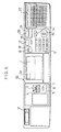
- Fig. 2 is a cross-sectional view showing the entire structure of a digital copying machine 30 which is one example of the above-mentioned digital copying machine.
- the digital copying machine 30 is provided with a scanner section 31, a laser printer section 32 that functions as an image-recording section, and a post-processing device 34 that includes a sorter.
- the scanner section 31 is provided with a document platen 35 made of transparent glass, a recirculating automatic document feeder 36 (hereinafter, referred to as RADF) for automatically supplying and feeding documents onto the document platen 35 and a scanner unit 40 that functions as a document image reading unit for scanning and reading an image of a document that has been placed on the document platen 35.
- the document image that has been read by the scanner unit 40 is sent as image information, that is, as image data, to an image-processing section, which will be described later, and predetermined image processing is carried out on the image data.
- the RADF 36 is a device that automatically feeds a plurality of documents that have been set on a predetermined document tray all together one by one onto the document platen 35 of the scanner section 31.
- the RADF 36 is provided with a transport path for one-sided documents, transport paths for double-sided documents, a transport-path switching mechanism and other mechanisms so that one side or double sides of a document can be scanned by the scanner unit 40 in accordance with selection made by the user.
- the scanner unit 40 is provided with a first scanning unit 40a, a second scanning unit 40b, an optical lens 43 and a CCD (Charge Coupled Device) 44.
- the first scanning unit 40a is composed of a lamp reflector assembly 41 that irradiates with light the surface of a document placed on the document platen 35 so as to scan it, and a second reflection mirror 42a.
- the second scanning unit 40b is composed of second and third reflection mirrors 42b and 42c.
- the first to third reflection mirrors 42a to 42c direct reflected light from the document to the CCD 44.
- the optical lens 43 converges the image of reflected light from the document onto the CCD 44 as an image thereon.
- the CCD 44 is an element that converts an image of reflected light from the document into an electric image signal.
- the scanner section 31 While successively placing documents onto the document platen 35, the scanner section 31 allows the scanner unit 40 to move along the lower surface of the document platen 35 and reads the document image so as to convert it into image data, through cooperative operations between the RADF 36 and the scanner unit 40.
- the image data, thus obtained from the scanner section 31, is sent to an image-processing section which will be described later, and after it has been subjected to various processes, the resulting data is temporarily stored in a memory 73 of the image-processing section. Thereafter, the image data is supplied to the laser printer section 32 in accordance with an instruction for output, and recorded onto a sheet of paper as an image.
- the laser printer section 32 is provided thereon with a laser-writing unit 46, and an electrophotographic process section 47 for forming images, and is provided thereunder with a paper store and transport section 55.
- the laser-writing unit 46 has a semiconductor laser for releasing a laser light beam in response to the image data from the memory 73, a polygon mirror for deflecting the laser light beam with a constant angular velocity, an f- lens for correcting the laser light beam that has been subjected to the deflection with a constant angular velocity so that it is subjected to a constant-velocity deflection on the photoconductor drum 48 in the electrophotographic process section 47, and other parts.
- the electrophotographic process section 47 is provided with the photoconductor drum 48, and devices, such as a charger, a developing device, a transfer device, a separating device, a cleaning device and a fixing device 49, all of which are disposed around the photoconductor drum 48.
- a transport path 50 is placed on the downstream side of the fixing device 49 in a transporting direction of a sheet of paper on which an image has been formed.
- the transport path 50 is separated into a transport path 57 that connects to the post-processing device 34 and a transport path 58 that connects to the sheet of paper store and transport section 55.
- the paper store and transport section 55 has a first cassette 51, a second cassette 52, a double-side copying unit 53 and a multilayered manual tray 54. Stacks of paper are housed in the first and second cassettes 51 and 52. When the user selects a cassette that contains paper of a desired size, sheets of paper are fed one by one from the stack of paper in the cassette, and successively transported toward the electrophotographic process section 47.
- the double-side copying unit 53 is either for reversing the front and back sides of a sheet of paper on which the image is formed by the electrophotographic process section 47 and then feeding the sheet of paper again to the electrophotographic process section 47, or for feeding the sheet of paper again to the electrophotographic process section 47 without reversing it.
- the image data which has been read from the memory 73, is released as a laser light beam from the laser writing unit 46, and formed as an electrostatic latent image on the surface of the photoconductor drum 48 in the electrophotographic process section 47.
- the electrostatic latent image is visualized as a toner image, and the toner image is electrostatically transferred onto a sheet of paper that has been transported from the paper store and transport section 55, and then is fixed on the sheet of paper by the fixing device 49.
- the sheet of paper on which the image has been formed in this manner is sent from the fixing device 49 to the post-processing device 34 through the transport path 50, or again to the electrophotographic process section 47 through the transport paths 50 and 58 and the double-side copying unit 53.
- the image-processing section carries out image processing on the image data of the document that has been obtained from the scanner section 31.
- the image-processing section is provided with an image-data input section 70, an image-data processing section 71, an image-data output section 72, a memory 73 that functions as an image information memory section and a print control unit 74 (hereinafter, referred to as PCU) that functions as a control section.
- PCU print control unit
- the PCU 74 which controls the entire operations of the digital copying machine 30, is constituted by a CPU (Central Processing Unit).
- the memory 73 which stores image data, is constituted by a RAM (Random Access Memory), a hard disk and other parts.
- the image-data input section 70 has a CCD section 70a, a histogram processing section 70b and an error-dispersion processing section 70c.
- the image-data input section 70 converts image data of a document that has been read by the CCD 42 into binary coded data, and processes the image data by using the error-dispersion method while representing the data as binary digital quantity in the histogram, thereby temporarily storing the resulting data in the memory 73.
- analog signals which correspond to respective pixel densities of the image data, are analog-to-digital converted, and then subjected to an MTF correction and a black-and-white correction, or a gamma correction, and the resulting signals are released to the histogram processing section 70b as digital signals with 256 gray scales (8 bit).
- the digital signals released from the CCD section 70a are added individually for the respective pixel densities of 256 gray scales; thus, density information (histogram data) is obtained.
- the histogram data is sent to the error-dispersion processing section 70c as pixel data, and also sent to the PCU 74, if necessary.
- the digital signals of 8 bits/pixel, released from the CCD section 70a are converted into one bit (binary coded) by the error-dispersion method which is one type of pseudo intermediate processing, that is, by the method for reflecting the error of binary coded digits to the binary coding decision between the adjacent pixels; thus, redistributing operations for exactly reproducing the densities of local regions of a document are carried out.
- the error-dispersion method which is one type of pseudo intermediate processing, that is, by the method for reflecting the error of binary coded digits to the binary coding decision between the adjacent pixels; thus, redistributing operations for exactly reproducing the densities of local regions of a document are carried out.
- the image-data processing section 71 is provided with multi-value processing sections 71a and 71b, a synthesis processing section 71c, a density-conversion processing section 71d, a magnification processing section 71e, an image-processing section 71f, an error-dispersion processing section 71g and a compression processing section 71h.
- the image-data processing section 71 serves as a processing section for converting the inputted image data into image date that is desired by the user. Various processes are carried out in this section until final output image data has been stored in the memory 73. Additionally, the above-mentioned processing sections, contained in the image-data processing section 71, are used on demand, and are not necessarily used.
- the image data that has been binary coded in the error-dispersion processing section 70c is again converted into data with 256 gray scales.
- logical operations that is, OR, AND or exclusive-OR operation, are selectively carried out for each pixel.
- the data used in this operation is pixel data stored in the memory 73 and bit data from a pattern generator (PG).
- the relationship of the output density to the input density is properly set with respect to the data with 256 gray scales based upon a predetermined gray-scale conversion table.
- the magnification processing section 71e pixel data (density value) on a target pixel that is to be obtained after a specified change in magnification is found by carrying out an interpolating process based on the inputted known data in accordance with a specified magnification. Thereafter, in accordance with the pixel data, the change in magnification is carried out in the sub-scanning direction, and then is carried out in the scanning direction.
- the image-processing section 71f various kinds of image processing is carried out on the inputted pixel data. Moreover, information extraction with respect to data rows, such as feature extraction, is carried out.
- the error-dispersion processing section 71g the same process as that carried out in the error-dispersion processing section 70c in the image-data input section 70 is carried out.
- the compression processing section 71h the binary data is compressed by a coding process that is referred to as "run length".
- the compression is operated in the last processing loop at the time when the final output image data has been complete.
- the image-data output section 72 is provided with a restoring section 72a, a multi-value processing section 72b, an error-dispersion processing section 72c and a laser output section 72d.
- the image-data output section 72 restores the image data that has been stored in the memory 73 in a compressed state so as to again convert it to the original data with 256 gray scales, carries out an error dispersion for quaternary data that provides smoother intermediate gray-scale expressions than binary data, and then transmits the resulting data to the laser output section 72d.
- the restoring section 72a the image data that has been compressed by the compression processing section 71h is restored.
- the multi-value processing section 72b carries out the same process as that carried out in the multi-value processing sections 71a and 71b in the image-data processing section 71.
- the error-dispersion processing section 72c carries out the same process as that carried out in the error-dispersion processing section 70c in the image-data input section 70.
- the digital pixel data is converted to a laser on/off signal in accordance with a control signal from a sequence controller which is not shown.
- the semiconductor laser in the laser-writing unit 46 is turned ON/OFF in response to the on/off signal, thereby allowing an electrostatic latent image to be written on the photoconductor drum 48.
- data which is dealt in the image-data input section 70 and the image-data output section 72, is basically stored in the memory 73 in the form of binary data so as to save the capacity of the memory 73; however, the data may be processed in the form of quarterary data in order to prevent the degradation of image data.
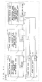
- Fig. 4 shows the arrangement of the control system effected by the PCU 74.
- Fig. 4 the following parts and sections are connected to the PCU 74: a desk-related load 75, an RADF-related load 76, an operation panel unit 77, a sorter control unit 78, a scanner-related load 79, a printer-related load 80 and the aforementioned image-data processing section 71.
- the PCU 74 supervises the above-mentioned parts by sequential control, and releases control signals to the respective parts upon controlling them.
- the desk-related load 75 is a load related to motors, clutches and other parts in the multi-stage paper-feed unit 33 and the sorter of the post-processing device 34 except for the digital copying machine main body.
- the RADF-related load 76 is a load related to motors, clutches, switches and other parts in the RADF 36.
- the scanner-related load 79 is a load related to motors, solenoids and other parts in the scanner unit 40.
- the printer-related load 80 is a load related to motors, solenoids, a high-voltage power source and other parts in the electrophotographic process section 47.
- the sorter control unit 78 which is provided with a CPU, controls the operation of the sorter in accordance with the control signal from the PCU 74.
- the operation panel unit 77 which has a CPU, is an input section for various settings such as copying modes, instructions, etc. that are inputted by the user to the digital copying machine 30.
- the operation panel unit 77 transfers a control signal, for example, corresponding to a copying mode that has been set by the user through an input operation, to the PCU 74.
- the PCU 74 operates the digital copying machine 30 in accordance with the corresponding mode in response to the control signal.
- the PCU 74 also transfers to the operation panel unit 77 a control signal that indicates the operation state of the digital copying machine 30.
- the operation panel unit 77 displays the current state on its display section in accordance with the control signal.
- the memory 73 connected to the image-data processing section 71, is constituted by a main memory 73a and a hard disk 73b which are made of, for example, semiconductor memories.
- An image-data communication unit 81 is connected to the main memory 73a.
- the image-data communication unit 81 is installed so as to make possible information communications with other digital information apparatuses through image data, image-control signals, etc.
- the image-data communication unit 81 corresponds to an interface 93a and a communication line 96.
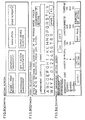
- the operation panel unit 77 is provided with an operation panel 90 which functions as an input section, as shown in Fig. 5.
- a liquid crystal display 1 which is a display section of a touch panel system, is placed in the center thereof.
- a screen-switching instruction area 1a is disposed on one part of the screen of the liquid crystal display 1.
- the screen-switching instruction area 1a is used for inputting an instruction for switching the display screen of the liquid crystal display 1 to a screen for selecting image-editing functions.
- various editing functions are displayed in a list on the screen of the liquid crystal display 1 so as to make it possible to select desired functions, as will be described later. In this case, when the user presses an area of a desired editing function among display areas of the various editing functions, the specified editing function is set.
- a brightness adjusting dial 2 which adjusts the brightness of the screen of the liquid crystal display 1, is placed on its left-end position as shown in Fig. 5.
- a magnification automatic setting key 3, a zoom key 4, fixed magnification keys 5 and 6, and an equal magnification key 7 are provided between the dial 2 and the liquid crystal display 1.
- the magnification automatic setting key 3 is used for setting the mode for automatically selecting the copy magnification
- the zoom key 4 is used for setting the copy magnification at a rate of 1 percentage point.
- the fixed magnification keys 5 and 6 are used for selecting a fixed magnification
- the equal magnification key 7 is used for returning the copy magnification to the reference magnification (equal magnification).
- a number setting key 13, a clear key 14, a start key 15, an all cancellation key 16, an interruption key 17, an operation guide key 18, a message forwarding key 19, a memory-transmission mode key 20, a copy/facsimile mode switching key 21, and one-touch dial key 22 are disposed.
- the number setting key 13 is used for setting the number of copies, and the clear key 14 is operated when the number of sheets is cleared, or when a continuous copying operation is stopped in the middle of the operation.
- the start key 15 is used for instructing the start of a copy process, and the all cancellation key 16 is used for cancelling all the presently set modes so as to return the machine to the reference state.
- the interruption key 17 is operated when upon a continuous copying process, another document is to be copied.
- the operation guide key 18 is operated when the user does not know how to use the digital copying machine 30, and upon pressing the key, the liquid crystal display 1 displays how to operate the digital copying machine 30.
- the message forwarding key 19 is used for switching the display of messages that have been displayed by the operation of the operation guide key 18 in a successive forwarding manner.
- the memory-transmission mode key 20, the copy/facsimile mode switching key 21, and the one-touch dial key 22 are setting keys related to facsimile mode.
- the memory-transmission mode key 20 is used for instructing that the transmit document be transmitted after having been temporarily stored in the memory
- the copy/facsimile mode switching key 21 is used for switching modes of the digital copying machine 30 between the copy and facsimile.
- the one-touch dial key 22 is used for dialing the phone to a receiver whose telephone number has been preliminarily stored in the digital copying machine 30 by a one-touch operation.
- the above-mentioned arrangement of the operation panel 90 related to various kinds, layout, etc. of keys is merely given as one example, and it may be modified depending on various functions to be installed in the digital copying machine 30.
- the liquid crystal display 1 is, for example, allowed to give the following displays on the screen: a basic screen as shown in Fig. 6(a), the first-function setting screen shown in Fig. 6(b), the second-function setting screen shown in Fig. 6(c), an image-quality setting screen shown in Fig. 7(a), a post-process setting screen as shown in Fig. 7(b), an initial setting screen shown in Fig. 8(a), a finger-print registration screen shown in Fig. 8(b), a department-management setting screen shown in Fig. 8(c), a limiter setting screen shown in Fig. 9(a), a simulation screen shown in Fig. 9(b), and other screens which will be described later.
- the basic screen is provided with a function setting region, an image-quality setting region, a post-process setting region, an initial setting region, an operation region for set-function confirmation and a cassette-setting region. These regions correspond to setting keys 101a through 101f. Moreover, the basic screen includes a set-cassette display, a density display, a copy-number display and a magnification display. When the above-mentioned operation region for set-function confirmation is operated, functions that have been set in the present image-forming system are displayed on the liquid crystal display 1.
- the first-function setting screen is provided with regions for setting various editing functions, such as mirror image, slanted character, inversion, shading, trimming and masking. These regions correspond to setting keys 102a through 102f. Moreover, operation regions are set so as to provide transitions to the basic screen and the next screen.
- the second-function setting screen is provided with regions for setting editing functions, such as synthesis and an independent change in magnification, and translation functions. These regions correspond to setting keys 103a through 103c. Moreover, operation regions are set so as to provide transitions to the basic screen and the next screen.
- the image-quality setting screen includes setting regions for setting the density, HI-FI (high-image-quality copying mode), background-elimination mode, automatic-magnification-change mode, character mode, character-photograph mixed mode, photograph mode and magnification.
- HI-FI high-image-quality copying mode
- background-elimination mode background-elimination mode
- automatic-magnification-change mode character mode
- character-photograph mixed mode photograph mode and magnification.
- displays are provided for density and magnification.
- the post-process setting screen is provided with an input region for determining whether a document in question is one-sided or double-sided, an input region for determining whether copying in question is made on one side or on double sides, and a setting region for binding functions. Moreover, setting regions for post-process functions, such as staple sorter, sorter and finish, and a setting region for electronic RDH are placed.
- the initial setting screen is provided with setting regions for various modes, such as finger-print registration, department management, simulation, maintenance management, new function registration, and output-device selection, as well as an operation region for making a transition to the basic screen.
- Transitions to the respective screens are carried out in accordance with the sequence shown in Fig. 10.
- the basic screen is first displayed, and on this display screen, when any of the function setting region, image-quality setting region, post-process setting region and initial setting region is pressed, the display screen is allowed to transfer to the screen corresponding to the specified region.
- the screen is switched to the first-function setting screen, and if the operation region for making a transition to the next screen is pressed on this screen, the screen is switched to the second-function setting screen (NEXT-function setting screen).
- the operation region for making a transition to the basic screen is pressed, the screen is switched to the basic screen.
- the screen when a slanted-character function setting region is pressed, the screen is switched to the slanted-character setting screen as shown in Fig. 12(c).
- This screen corresponds to, for example, function-2 parameter setting screen in Fig. 10.
- the slanted-character setting screen is provided with an angle input key 106a that is a setting region for a slanted angle and a setting completion key 106b that is an input region for setting completion. Furthermore, the resulting slanted angle is displayed.
- the screen of the liquid crystal display 1 is switched to a corresponding parameter setting screen such as the above-mentioned slanted-character setting screen.
- Table 1 shows examples of image-editing functions and their process operations that are provided in the present image-forming system and that can be set by the operations of the above-mentioned function setting regions.
- the image-editing functions that are set in the present image-forming system are not intended to be limited thereby.
- other functions such as a function for making a fair copy of hand-written characters and images, may be provided.
- Image-editing functions Outline of processing Independent change in magnification Sets different magnifications with respect to the longitudinal and lateral directions of a document image. Sharpness Adjusts the image quality of a copy.
- Margin for binding Makes a margin in a copy with a desired width. Erasure of frame Makes a copy with its frame erased.
- Centering Makes a copy virtually in the center of a sheet of copy paper. 2 copies in one set Copies a book. Address copy Outputs a copy image with an address synthesized therein. Multishot Combines and copies images from a plurality of pages on one sheet. Trimming Copies only a specified portion. Masking Makes a copy with a specified portion erased. Shifting function Makes a copy with a document image shifted to a desired position. Composite function Composes and copies a plurality of document images. Black-white inversion Makes a copy with a negative/positive inversion. Net process Makes a copy with a net providing/erasing process. Shading Makes a copy with shades. Framing Makes a copy with its image framed.
- Slanted image Makes a copy with its image slanted.
- Mirror image Makes a copy with its image inverted like a mirror image.
- Repeat copy Copies a plurality of the same images on one sheet.
- 2 in 1 copy Copies a set of two documents on one sheet.
- Dated copy Makes a copy with the date written therein.
- Center mark Copies an image with a center mark added thereto.
- Enlarged divisional output Copies an enlarged document onto a plurality of sheets in a divided manner.
- High-image-quality process Makes a copy using a high-image-quality process.
- the present image-forming system is composed of digital information apparatuses installed in an office.
- the image-forming system shown in Fig. 11 is provided with digital copying machines 91 through 93, a scanner 94 and a printer 95 that functions as image-forming apparatuses.
- the digital copying machine 91 is a low-function, inexpensive, memoryless one, and merely has basic editing functions.
- “memoryless” means that although a page memory capable of storing a lot of image data is not provided, at least a line memory required for carrying out normal jobs for image data in a digital copying machine is provided.
- basic editing functions are those functions, such as black-white inversion, that can be carried out without the need for a page memory.
- the scanner function provided by the scanner unit 40 in Fig. 2
- the scanner function provided by the scanner unit 40 in Fig. 2
- the copy speed is set to 20 CPM (20 sheets/minute), which is typical for low-speed models.
- the printer function provided by the laser printer section 32, is set to 400 DPI in the case of a monochrome process, and an interface (I/F) 91a is also installed.
- the digital copying machine 92 has a scanner function of a resolution of 400 DPI in the case of a monochrome process, a printer function of 400 DPI in the case of a monochrome process, and a copy speed of 40 CPM, which are typical for middle-class apparatuses. Further, there are installed various editing functions, a memory of 64 bytes (a capacity corresponding to 4 pages in A4-size with 400 DPI, 8 bits/pixel) that functions as a page memory, and an interface 92a. The memory is referred to as the main memory 73a shown in Fig. 4.
- the digital copying machine 93 has a scanner function of a resolution of 400 DPI in the case of a monochrome process, a printer function of 400 DPI in the case of a monochrome process, and a high copy speed of 60 CPM. Further, there are installed various editing functions, a character-recognizing function, a coding function for bit data, and a memory of a large capacity of 500 M bytes (a capacity corresponding to 100 pages in A4-size with 400 DPI, 8 bits/pixel at a compression rate of 1/4) that functions as a page memory, which are regarded as high-class functions. Therefore, the digital copying machine 93 makes it possible to carry out a process for changing the order of pages of image data and also to store document data in various formats.
- the above-mentioned memory corresponds to a memory including the main memory 73a and the hard disk 73b shown in Fig. 4. Further, the digital copying machine 93 is provided with an interface 93a.
- the scanner 94 which can read color images, has a resolution of 600 DPI.
- the printer 95 which can print color images, has a recording density of 600 DPI.
- These scanner 94 and printer 95 is provided with an interface 94a and an interface 95a respectively.
- the digital copying machine 91, digital copying machines 92 and 93, scanner 94 and printer 95 are connected through the respective interfaces 91a to 95a and the communication line 96, and allowed to transmit and receive data with each other. Therefore, the communication apparatus is constituted by the interfaces 91a to 95a, communication line 96 and PCU 74.
- kinds of data handled by the communication apparatus are, for example, bit data such as image data (gray scale data for every pixel, e.g., 8 bits, 256 gray scales) and command codes.
- the communication apparatus is capable of transmitting high gray-scale images, such as nature images, highly accurately.
- the communication apparatus is capable of reducing data amount of text data, such as characters, by coding it and then transmitting the coded data at a high speed.
- image data with gray scales such as nature images may be generally handled with the Dither technique (method) that is one of area gray scale methods for compressing data amount, the error-dispersion method, and other methods, and then transferred.
- the error-dispersion method is carried out in advance in respective devices.
- the format for transmitted data is set in accordance with a format that can be handled by the respective digital copying machines 91 to 93 or the printer 95. Therefore, for example, in a digital copying machine having received image data that is to be outputted onto a sheet of paper, the image data is inputted to the laser printer section 32 and then converted to a data row required when writing in the image-processing section; thereafter, the image data is outputted.
- the interfaces 91a to 95a are defined by protocol and communication speed that are individually specified. An appropriate standard is therefore selected depending upon content of transmitted data (e.g., data amount), relative locations of the devices (e.g., distances) etc. Moreover, in the present image-forming system, devices are not always in one-to-one connection with each other. A plurality of devices may be connected to the common communication line 96, as in a dizzy chain. Therefore, the devices are provided with respective addresses so that the interfaces 91a to 95a can recognize the receiver of image data. Moreover, the interfaces 91a through 95a employ as the standard, for example, Ethernet that is a network capable of transferring image data at high speeds. Furthermore, the interfaces 91a through 95a are compatible with commonly-used standards such as SCSI (Small Computer System Interface) and RS-232C.
- each of the digital copying machines 91 through 93 has a FAX function for transmitting and receiving data through a telephone line and a printer mode for printing document data released from a personal computer, a word processor and other devices.
- digital copying machines that are installed in the respective offices have a lot of variations in their functions depending on their prices, capacities of image memory and other aspects, and various types of them are used depending on purposes for use in respective offices and degrees of demand for various functions. Therefore, with respect to the digital copying machines installed in the offices, a number of commodities may be used without being limited to the digital copying machines 91 through 93.
- the following table 2 shows one example of image-editing functions that are provided in the digital copying machines 91 through 93.
- the present image-forming system is so arranged that the digital copying machine 93 having the most image-processing functions and the memory 73 of a large capacity functions as the main image-forming apparatus, i.e., the main digital copying machine, and the other digital copying machines 91 and 92, scanner 94 and printer 95 are connected to the digital copying machine 93.
- the other digital copying machines 91 and 92 are so arranged that they can use the image-processing functions and the memory 73 of the digital copying machine 93.
- image data is transmitted from one of the digital copying machines 91 and 92 to the digital copying machine 93, which then carries out predetermined image processing on the above-mentioned image data.
- the resulting image data is returned to, for example, the original digital copying machine and then outputted onto a sheet of paper as an image.
- image data is transmitted from one of the digital copying machines 91 and 92 to the digital copying machine 93, the memory 73 of which stores the image data.
- the image data is returned to, for example, the original digital copying machine when necessary.
- the PCU 74 in the digital copying machine 91 makes a judgement as to whether or not the set functions include any function that is inoperable in the digital copying machine 91 (S3).
- the digital copying machine 91 does not have a "slanted-character” function although it has a "black-white inversion” function. Therefore, the result of judgement at S3 is "YES". Accordingly, the information that "slanted character” is inoperable in the digital copying machine 91 and the information that the digital copying machine 93 should be used for processing "slanted character” are displayed on the liquid crystal display 1 (S4). Such a display screen is shown in Fig. 12(b).
- the digital copying machine 91 does not have a page memory and only has a line memory, the image data is successively processed as image data that is read line by line.
- the line memory is installed, for example, inside the PCU 74, and used when the PCU 74 is operated.
- the image data that has been subjected to the "black-white inversion” process is successively transferred to the digital copying machine 93 (S8).
- a control-use command code that is, a command code for instructing the "slanted-character” process
- image data that is to be subjected to the "slanted-character” process are inputted to the digital copying machine 93 through the interface 91a, the communication line 96 and the interface 93a.
- a scramble process is carried out on the image data before the transmission of the image data (S7).
- modem are provided to convert digital data into signals that are appropriate for transmission via the communication line 96.
- the scramble process is carried out so as to prevent the image data from leaking out.
- the communication apparatus carries out communication via a general purpose network
- a number of unidentified people can freely access the network, and there is a possibility that data flowing through the network might be illegally taken by a person such as a hacker. Therefore, such leakage of image data is prevented by the scrambling process.
- the digital copying machine 93 unscrambles the data sent from the digital copying machine 91 (S9). Then, the digital copying machine 93 confirms the contents of process that are requested through a command code, and carries out a "slanted-character" process on the image data that has already subjected to the "black-white” inversion process in accordance with the contents of the request (S10).
- the digital copying machine 93 After the processes on the image data are completed, the digital copying machine 93 carries out the scramble process (S11) on the image data that are already subjected to those processes. Then, in the reverse order from the previous case, the digital copying machine 93 sends back the image data to the digital copying machine 91 that is the sender of the image data (S12).
- the digital copying machine 91 unscrambles the received data (S13) and outputs the image data on a sheet of paper as an image (S14).
- the digital copying machine 91 here operates in the same manner as the digital copying machines 30 that is already explained.
- the image-editing can be carried out by assigning it to the digital copying machine 93. Therefore, the digital copying machines 91 and 92 other than the digital copying machine 93 are not necessarily provided with as high image-editing functions and the like as the digital copying machine 93 is.
- the operation is designed so that the process is assigned to the digital copying machine 93 after the execution key 112a is pressed in S5; however, the operation may be alternatively designed so that if a function that is inoperable in the digital copying machine 91 side is selected in S3, the process is assigned to the digital copying machine 93 without confirming in S5 whether or not the execution key 112a has been pressed.
- the operation is designed so that the image data already subjected to processes in the digital copying machine 93 is returned to the digital copying machine 91 that is the sender of the image data, and the image is then outputted by the digital copying machine 91; however, the operation may be alternatively designed so that an apparatus to which the already processed image data is returned is selected in accordance with various conditions, and the image is outputted by the selected digital copying machine or printer.
- the present image-forming system may be arranged so that the operations S21 through S26 shown in Fig. 13 are carried out between the operations S13 and S14.
- the memory 73 capable of storing image data for a plurality of pages is needed to carry out these operations. Therefore, the operations are carried out by a communicating operation of the digital copying machines 92 and 93 in the image-forming system shown in Fig. 11.
- the digital copying machines 91 through 93 are designed, for example, to be capable of displaying "Waiting time: N seconds" on the liquid crystal display 1, as shown in Fig. 14. Meanwhile, the user may leave the digital copying machine 92 unattended after confirming the above-mentioned display.
- the image processing may be completed and the image may be outputted when the user is not present.
- the image processing may be completed and the image may be outputted when the user is not present.
- the present digital copying machine is designed so that the user can select either the operation 1 ⁇ or 2 ⁇ .
- Fig. 14 shows a display in the operation 3 ⁇ .
- the progress of the image processing is indicated in percent.
- the progress indicated as 100 % means that the image data that is already subjected to the image processing is stored in the memory 73.
- the image data that is already processed in the digital copying machine 93 is stored in the memory 73 page by page (S21). Thereafter, as the storing is completed with respect to the previous image data (S22), the PCU 74 judges in advance whether or not a direct print instruction has been inputted (S23). If there is a direct print instruction, the operation proceeds to S14 and the laser printer section 32 outputs the image data.
- the direct print instruction is an instruction to order the laser printer section 32 to output the processed image data as soon as the digital copying machine 92 receives the processed image data. The order of the instruction is inputted by pressing the start key 15 shown in Fig. 5, for example, after a predetermined image-processing function is set.
- the processed image data is not outputted and the PCU 74 is in a stand-by state until a print instruction is inputted by the user pressing the start key 15. In this state, for example, if the start key 15 is pressed, the operation proceeds to S14, and the processed image data is outputted. If a confirmation key 104a is pressed in the above-mentioned stand-by state, since the image processing is completed, the display of the liquid crystal display 1 shown in Fig. 14 indicates that the progress is 100 % and that the waiting time is 0 second, and also shows a message that the image processing is completed.
- Fig. 14 shows a display example of the liquid crystal display 1 when the confirmation key 104a is pressed before the image processing in the digital copying machine 93 is completed.
- the present image-forming system is arranged so that digital copying machines can copy documents by using the memory 73 of the digital copying machine 93.
- the operation of the present image-forming system of this kind is provisionally explained with the communicating operation of the digital copying machines 92 and 93.
- the digital copying machine 92 is provided with an electronic RDH function.
- This electronic RDH is for temporarily storing all image data of, for example, a 10 page document in a memory, and sequentially calling the image data page by page from the memory in a repeated manner until 20 sets of copied documents are made.
- the electronic RDH can be selected by operating the function-setting key 101a shown in Fig. 6(a).
- an electronic RDH setting key is displayed, for example, on the second-function setting screen shown in Fig. 6(c) by operating the function-setting key 101a.
- the digital copying machine 92 has a page memory of 64 M bytes as the memory 73. Therefore, the page memory can successively read 4 pages in A4-size document of the image data of 256 gray scales. This capacity is large enough to copy documents by temporarily storing document image in a normal copying process. However, if, for example, 10 pages of document image is to be copied for a plurality of sets with the electronic RDH, the page memory is short for 6 pages. Therefore, in this case, the memory 73 of the digital copying machine 93 is used to carry out the electronic RDH. Referring to the flow chart in Fig. 15, the following description will discuss the operation in this case.
- the electronic RDH is selected in the digital copying machine 92, and documents are set on the RADF 36 shown in Fig. 2 (S31).
- the start key 15 shown in Fig. 5 is turned ON (S32)
- the RADF 36 sequentially transports the documents, image of which is to be read by the scanner unit 40.
- the image data thus obtained is sequentially stored in the memory 73 (S33).
- the image data is sequentially subjected to the density conversion process, the magnification process in accordance with the setting, and other processes in the image-data processing section 71 (S34).
- an external-memory selection key 121a shown in Fig. 16(a) is set on the liquid crystal display 1, and memory capacity is indicated by an available memory amount display section 121b.
- the message display shown in Fig. 16(a) is not carried out.
- the empty capacity of the memory 73 becomes less than the memory capacity required for reading the remaining document (S35). If the external-memory selection key 121a is not pressed in advance (S36), a message indicating that an external memory is needed is displayed on the liquid crystal display 1 (S37) as shown in Fig. 16(a).
- the liquid crystal display 1 displays a message shown in Fig. 16(b).
- the external-memory selection key 121a is displayed in an inverted state, and the display at the available memory amount display section 121b is a capacity display including the capacity of the memory 73 of the digital copying machine 93.
- the image data is transmitted to the digital copying machine 93 (S40) to use the memory 73 of the digital copying machine 93 as the external memory.
- the display of the liquid crystal display 1 at this time is shown in Fig. 16(c).
- the image data transmitted in this case is either image data sequentially read afterwards or image data already read and stored in the memory 73.
- the transmission operation of the image data is carried out in the same manner as the sending operation of the image data mentioned earlier.
- the digital copying machine 93 stores the received image data in the memory 73 thereof.
- the operations S33 through S40 are repeated until there is no more document to be read (S41). Thereafter, as the reading of all the documents is completed, if the external memory is in use (S42), the image data is transmitted from the digital copying machine 93 to the digital copying machine 92 in accordance with an output sequence and outputted as images on sheets of paper (S43). In this case, the images are outputted sequentially from the last page of the documents. Moreover, the image data is read from respective memories in the same manner as it is written: if the image data is read from the memory 73 of the digital copying machine 92, it is read through a data line in the digital copying machine 92, and if the image data is read from the digital copying machine 93, it is read through the communication line 96.
- the page memory of the digital copying machine 92 is arranged to be used only for storing the image data read from the document image; however, a region corresponding to a few pages that is a part of the page memory may be arranged to be always set aside for control operation of the digital copying machine 92.
- the present image-forming system is arranged so that if the digital copying machine 93 that functions as the main digital copying machine is assigned by another digital copying machine a process, such as image processing and storage, that surpasses the processing abilities of the digital copying machine 93, the display that the processing cannot be carried out in the digital copying machine 93 is carried out by the liquid crystal display 1 of the digital copying machine that has assigned the process.
- the operation in this case is as follows.
- the PCU 74 of the digital copying machine 93 confirms contents of assignment by another digital copying machine.
- the digital copying machine 93 carries out the process: if inoperable, the digital copying machine 93 sends data indicating that the process is inoperable in the digital copying machine that has assigned the process.
- the digital copying machine that has assigned the process displays the data on the liquid crystal display 1 upon receiving it.
- the digital copying machine 93 that functions as the main digital copying machine grasps processing functions of the other digital copying machines, i.e., the digital copying machines 91 and 92, that make up the present image-forming system, and the total image-processing abilities of the system.
- the digital copying machine 93 is also designed to convey information about the total processing abilities of the system to other digital copying machines.
- the digital copying machine 93 starts communication with other digital copying machines (S51), and gathers from the other copying machines information about image-processing functions thereof (S52). Thereafter, the digital copying machine 93 sorts out and manages the obtained information (S53), and transmits the information to the other digital copying machines (S54).
- the digital copying machines including the digital copying machine 93, are thereby enabled to display, on the liquid crystal displays 1, image-processing functions of the digital copying machines incorporated in the image-forming system. Therefore, the user of the respective digital copying machines can confirm the functions of the digital copying machines according to the display.
- the present image-forming system is arranged so that in a case when image processing is assigned to the digital copying machine 93 that functions as the main digital copying machine, and also, for example, in a case when this digital copying machine 93 cannot carry out the image processing in accordance with the assignment, the digital copying machine 93 further assigns the process to a digital copying machine that is capable of carrying out the processing.
- the digital copying machine 93 stores in the memory 73 data about contents of the image-processing assignment and image data to be processed, that have been transmitted from the digital copying machine that has assigned the processing, and further transmits the data to a selected digital copying machine and assigns the processing thereto.
- the digital copying machine 93 that has a large memory capacity, is appropriate as the main digital copying machine.
- the digital copying machine that assigns the processing corresponds to the digital copying machine 91
- the digital copying machine selected by the digital copying machine 93 as the digital copying machine that carries out the processing corresponds to the digital copying machine 92.
- Conditions for the digital copying machine selected by the main digital copying machine are: for instance, a digital copying machine that is standing by, has an ability to carry out processing at high speeds, has image-processing functions of a new version, and has a large enough empty capacity left in the memory 73.
- the superiority order of the digital copying machines in the system with respect to functions thereof is changed, and also the image-forming system includes digital copying machines that have the same image-processing function and that have memories of the same capacity. Therefore, if a digital copying machine of the latest version or of the largest memory capacity is selected from the digital copying machines having the same image-processing functions as the copying machine that is to be assigned the image processing, the image data can be processed at high speeds and with high quality. The same conditions for selection are applied in a case when the main digital copying machine is set.
- the image processing can be carried out in a short period of time. Therefore, the image-forming system can quickly respond to an instruction and demand of the user.
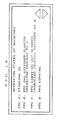
- the digital copying machine 93 is provided with a management function for grasping present operation states of the other digital copying machines, as well as the above-mentioned management function for the total processing abilities of the system that has been explained in accordance with the flow chart in Fig. 17. Referring to the flow chart in Fig. 18, the following description will discuss operations of this function.
- the digital copying machine 93 starts communication with other digital copying machines (S61), and gathers from the other copying machines information about operation states thereof (S62).
- the PCUs 74 manage the states of the respective digital copying machines. Therefore, the above-mentioned information is obtained by accessing the PCUs 74. Thereafter, the digital copying machine 93 sorts out the obtained information (S63), and transmits the sorted state data of the digital copying machines to the digital copying machines (S64).
- the digital copying machines are thereby enabled to display, for example, as shown in Fig. 19 on the liquid crystal display 1 in accordance with the above-mentioned state data.
- PPA corresponds to the digital copying machine 92
- PPB corresponds to the digital copying machine 91
- PPC corresponds to the digital copying machine 93
- PPD to the printer 95.
- the above-mentioned management functions facilitates management of the whole image-forming system by a serviceman and the like.
- the digital copying machine that assigns the processing transmits to the digital copying machine 93 a command code representing contents of the image processing and image data to be processed.
- the digital copying machine 93 stores the data in the memory 73, confirms the assigned image data in accordance with this data, and selects a digital copying machine that is capable of carrying out the image processing (S72).
- the digital copying machine 93 selects the most appropriate digital copying machine from the digital copying machines selected in S72 in accordance with the above-mentioned conditions (S73). Thereafter, the digital copying machine 93 transmits to the selected digital copying machine the image data and command code for ordering the image processing. The selected digital copying machine thereby carries out the assigned image processing (S74).
- the processed image data is returned via the digital copying machine 93 to, for example, the digital copying machine that has assigned the processing.
- the laser printer section 32 of that digital copying machine outputs the processed image data as an image.
- the system may be arranged so that the processed image data is outputted by the laser printer section 32 of the digital copying machine that has carried out the image processing.
- the system is arranged so that the digital copying machine 93 selects a digital copying machine that carries out the image processing and the selected digital copying machine automatically carries out the image processing.
- the system may be arranged to leave to selection by the user the decision whether the processing is to be carried out by the digital copying machine selected by the digital copying machine 93.
- the digital copying machine finally selected by the digital copying machine 93 in S73 is displayed on the liquid crystal display 1 of the digital copying machine that has assigned the processing, and a message asking whether the processing is operable in that digital copying machine. Thereafter, in a case when the user inputs "operable", the operation proceeds to S74 and the processing is carried out.
- the processing is suspended.
- the present image-forming system is arranged so that in a case when the digital copying machine 93 that functions as the main digital copying machine is assigned image processing by another digital copying machine and carries out the image processing as shown in Fig. 1, and also in a case when the digital copying machine selected by the digital copying machine 93, that is assigned image processing by another digital copying machine, carries out the image processing as shown in Fig. 20, if the digital copying machine that carries out the image processing is further ordered with an input through the operation panel 90 to carry out the image processing on image data read by the scanner section 31 thereof, one of the three following operations is carried out. Adoption of any of the three arrangements enables highly efficient processing.
- the first one is an arrangement carrying out the image processing on the image data assigned by another digital copying machine (hereinafter, will be referred to as the assigned image data), and the image processing on the image data read by the scanner section 31 of the digital copying machine that carries out the image processing (hereinafter, will be refereed to as the read image data) in a parallel manner.
- This arrangement is possible when an image-processing section of that digital copying machine can carry out the image processing at high speeds, and the memory 73 has a large capacity.
- the second one is an arrangement temporarily suspending the image processing on the assigned image data and carrying out the image processing on the read image data first.
- the image processing is suspended, and the image data processed so far and processing situation thereof are stored in the memory 73. Then, after the image processing on the read image data is completed, the image processing on the assigned image data is restarted.
- the third one is an arrangement assigning the image processing on the read image data to another digital copying machine capable of carrying out the image processing with the operations shown in Fig. 20, and only carrying out the image processing on the present assigned image data.
- the digital copying machines 91 through 93 are in scope of the above explanation; however, a combination of the scanner 94 and the printer 95, also being able to function as a digital copying machine, may be in scope of the explanation in the same manner as the digital copying machine.
- the image data obtained by the reading of, for example, scanner 94 is transmitted to the digital copying machine 93 and then subjected to the image processing, and the processed image data is transmitted to the printer 95 to be printed.
- the present image-forming system is provided with, for example, six digital copying machines 201 through 206 as shown in Fig. 21.
- the digital copying machines 201 through 206 have interfaces 201a through 206a, respectively, for communicating with each other.
- the digital copying machine 201 having a memory 73 of the largest capacity and the digital copying machine 202 having the most image-processing functions are main digital copying machines that function as main image-forming apparatuses in the present image-forming system.
- the digital copying machine 201 and the digital copying machine 202 are connected to enable communication with each other via the interfaces 201a and 202a thereof and the communication line 96.
- the digital copying machines 203 through 206 are connected in the same manner to enable communication with the digital copying machine 201 via the interfaces 201a and 203a through 206a thereof and the communication line 96.
- the digital copying machines 202 to 206 are arranged to be able to communicate with digital copying machines other than the digital copying machine 201 via the digital copying machine 201.
- the present image-forming system is arranged so that the digital copying machines 201 and 202 constitute the main digital copying machines, and the main digital copying machines are capable of carrying out the operations explained above in the explanatory example.
- functions of the digital copying machine 202 correspond to the digital copying machine 93 shown in Fig. 11, and functions of the digital copying machine 201 include less image-forming functions and a larger memory capacity than the digital copying machine 93.
- functions of the digital copying machines 203 and 204 correspond to the digital copying machine 92, and functions of the digital copying machines 205 and 206 correspond to the digital copying machine 91.
- the digital copying machines 201 and 202 constituting the main digital copying machines share jobs as follows: the digital copying machine 201 is mainly in charge of managing image data that needs the large capacity of the memory 73, and the digital copying machine 202 is in charge of image processing.
- image data sent from the digital copying machine 203 is stored in the memory 73 of the digital copying machine 201, and then sequentially sent to the digital copying machine 202 to be subjected to the image processing.
- the processed image data is again stored in the memory 73 of the digital copying machine 201, and then returned from the digital copying machine 201 to the digital copying machine 203.
- Such control is carried out in, for example, the PCU 74 of the digital copying machine 201.
- main digital copying machine that requires advanced functions is constituted by one digital copying machine
- arranging the main digital copying machine with such job sharing among a plurality of digital copying machines can cut down the cost, and also improve the efficiency of the image-forming system.
- the image data is stored in the memory 73 of the digital copying machine 201, and sequentially sent to the digital copying machine 202 to be subjected to the image processing. Therefore, such a job sharing makes it possible to efficiently carry out the image-processing operations without putting a large burden on the digital copying machine 202 that carries out the image processing.
- the present image-forming system is provided with, for example, five digital copying machines 211 through 215 as shown in Fig. 22.
- the digital copying machines 211 through 215 have interfaces 211a through 215a, respectively, for communicating with each other.
- the digital copying machines 211 through 215 are connected via the interfaces 211a through 215a and a communication line 96 so as to form a loop-like network.
- the digital copying machines 211 through 215 have an arrangement corresponding to the above-mentioned digital copying machine 30.
- the last-mentioned image-forming system is arranged so that if any of the digital copying machines 211 through 215 does not have a desired image-forming function, the image processing on image data is assigned to one of the other digital copying machines. Therefore, each of the digital copying machines 211 through 215 has information about image-processing functions and memory capacities of the other digital copying machines. The operations for obtaining this information are the same as the operations by the predetermined digital copying machine shown in Fig. 17.
- the assigning operation of the image processing may be designed so that each of the digital copying machines automatically selects a digital copying machine that is to be assigned the image processing, or so that the respective liquid crystal displays 1 display digital copying machines capable of carrying out the processing so as to be selected by the user.
- the image-forming system is designed to carry out the same operations as the image-forming system according to the above-described explanatory example.
- the digital copying machine that is assigned image processing by a digital copying machine that assigns the image processing is not a main digital copying machine, but another digital copying machine having that image-processing function.
- This arrangement of the present image-forming system that does not specify the main digital copying machine, is effective when the digital copying machines 211 through 215 have different image-forming functions from each other.
- the present image-forming system enables the image processing to be carried out by another image-forming apparatus connected to that image-forming apparatus via the communication apparatus. Therefore, the individual image-forming apparatuses constituting the image-forming system are not necessarily provided with the predetermined image-forming function. This decreases economic burden on the user of the image-
Applications Claiming Priority (4)
| Application Number | Priority Date | Filing Date | Title |
|---|---|---|---|
| JP34188795A JP3265175B2 (ja) | 1995-12-27 | 1995-12-27 | 画像形成システム |
| JP34188795 | 1995-12-27 | ||
| EP96120088A EP0782325B1 (fr) | 1995-12-27 | 1996-12-13 | Système de formation d'images |
| EP02006898A EP1223744B1 (fr) | 1995-12-27 | 1996-12-13 | Système de formation d'images en couleurs |
Related Parent Applications (3)
| Application Number | Title | Priority Date | Filing Date |
|---|---|---|---|
| EP02006898A Division EP1223744B1 (fr) | 1995-12-27 | 1996-12-13 | Système de formation d'images en couleurs |
| EP96120088.8 Division | 1996-12-13 | ||
| EP02006898.7 Division | 2002-03-26 |
Publications (3)
| Publication Number | Publication Date |
|---|---|
| EP1349372A2 true EP1349372A2 (fr) | 2003-10-01 |
| EP1349372A3 EP1349372A3 (fr) | 2003-11-26 |
| EP1349372B1 EP1349372B1 (fr) | 2008-08-20 |
Family
ID=18349515
Family Applications (3)
| Application Number | Title | Priority Date | Filing Date |
|---|---|---|---|
| EP96120088A Expired - Lifetime EP0782325B1 (fr) | 1995-12-27 | 1996-12-13 | Système de formation d'images |
| EP03015116A Expired - Lifetime EP1349372B1 (fr) | 1995-12-27 | 1996-12-13 | Système de formation d'image |
| EP02006898A Expired - Lifetime EP1223744B1 (fr) | 1995-12-27 | 1996-12-13 | Système de formation d'images en couleurs |
Family Applications Before (1)
| Application Number | Title | Priority Date | Filing Date |
|---|---|---|---|
| EP96120088A Expired - Lifetime EP0782325B1 (fr) | 1995-12-27 | 1996-12-13 | Système de formation d'images |
Family Applications After (1)
| Application Number | Title | Priority Date | Filing Date |
|---|---|---|---|
| EP02006898A Expired - Lifetime EP1223744B1 (fr) | 1995-12-27 | 1996-12-13 | Système de formation d'images en couleurs |
Country Status (4)
| Country | Link |
|---|---|
| US (1) | US6100992A (fr) |
| EP (3) | EP0782325B1 (fr) |
| JP (1) | JP3265175B2 (fr) |
| DE (3) | DE69623742T2 (fr) |
Cited By (1)
| Publication number | Priority date | Publication date | Assignee | Title |
|---|---|---|---|---|
| EP1708475A1 (fr) * | 2005-04-01 | 2006-10-04 | Canon Kabushiki Kaisha | Procédé d'arrêt correct d'un appareil de traitement des données utilisé dans une grille informatique |
Families Citing this family (16)
| Publication number | Priority date | Publication date | Assignee | Title |
|---|---|---|---|---|
| US7079269B2 (en) * | 1998-03-19 | 2006-07-18 | Océ-Technologies B.V. | Interactive printing with a plurality of printer devices |
| JP3675233B2 (ja) * | 1999-06-22 | 2005-07-27 | コニカミノルタホールディングス株式会社 | 画像形成装置 |
| EP1439696A4 (fr) * | 2001-10-23 | 2005-07-06 | Seiko Epson Corp | Controle de sortie d'images utilisant des donnees de controle de traitement d'images |
| US20030128384A1 (en) * | 2002-01-04 | 2003-07-10 | Nelson Dean S. | Dynamic load-balancing print server systems and methods |
| US7375836B1 (en) * | 2002-10-24 | 2008-05-20 | Ricoh Comapny, Ltd. | Copier with job sharing and forwarding capability |
| JP2004297772A (ja) * | 2003-03-12 | 2004-10-21 | Ricoh Co Ltd | 画像処理システム、画像形成装置、画像処理方法、プログラム及び記憶媒体 |
| JP4566679B2 (ja) | 2003-11-13 | 2010-10-20 | キヤノン株式会社 | 画像形成装置および制御方法およびプログラム |
| JP2005148396A (ja) * | 2003-11-14 | 2005-06-09 | Fuji Photo Film Co Ltd | プリントシステム |
| JP4468026B2 (ja) * | 2004-03-16 | 2010-05-26 | 株式会社沖データ | 画像形成装置 |
| JP4494987B2 (ja) | 2005-01-17 | 2010-06-30 | 株式会社東芝 | 多機能端末装置、稼働情報推測装置、稼働情報推測方法 |
| JP4586639B2 (ja) * | 2005-06-07 | 2010-11-24 | コニカミノルタビジネステクノロジーズ株式会社 | 画像処理システム、画像処理装置および画像処理プログラム |
| JP5053072B2 (ja) * | 2007-01-31 | 2012-10-17 | 株式会社リコー | 多機能プリンタなどの画像処理装置における組み込み機能と外部機能のシームレスな切り換え、機能の除去および追加、画像のサムネイル/プレビューならびにユーザー認証のためのシステムおよび方法 |
| JP5543060B2 (ja) * | 2007-10-23 | 2014-07-09 | キヤノン株式会社 | ジョブ処理システム及びジョブ処理方法、記憶媒体及びプログラム |
| JP4670903B2 (ja) * | 2008-05-30 | 2011-04-13 | コニカミノルタビジネステクノロジーズ株式会社 | 画像処理システム、画像処理装置の制御方法および画像処理装置の制御プログラム |
| JP5708017B2 (ja) * | 2011-02-23 | 2015-04-30 | 株式会社リコー | 情報処理システム、情報処理機器、プログラム |
| JP7230676B2 (ja) * | 2019-05-13 | 2023-03-01 | 京セラドキュメントソリューションズ株式会社 | 画像形成システム |
Citations (2)
| Publication number | Priority date | Publication date | Assignee | Title |
|---|---|---|---|---|
| GB2288508A (en) * | 1994-04-06 | 1995-10-18 | Offset Studios Ltd | An image processing method |
| US5564109A (en) * | 1991-09-13 | 1996-10-08 | Eastman Kodak Company | Remote user interface for prioritizing and selecting from a plurality of document production peripheral devices |
Family Cites Families (11)
| Publication number | Priority date | Publication date | Assignee | Title |
|---|---|---|---|---|
| JPS53116834A (en) | 1977-03-22 | 1978-10-12 | Ricoh Co Ltd | Copying system |
| US4167322A (en) * | 1977-08-11 | 1979-09-11 | Ricoh Company, Ltd. | Electrostatic copying system having monitoring devices |
| US4797706A (en) * | 1985-02-28 | 1989-01-10 | Canon Kabushiki Kaisha | Multi-unit image processing system with central control |
| JPH0736592B2 (ja) | 1985-02-28 | 1995-04-19 | キヤノン株式会社 | 画像処理装置 |
| US5287194A (en) * | 1992-11-25 | 1994-02-15 | Xerox Corporation | Distributed printing |
| US5511150A (en) * | 1993-11-29 | 1996-04-23 | Eastman Kodak Company | Copier/printer with improved productivity |
| US5935217A (en) * | 1994-04-19 | 1999-08-10 | Canon Kabushiki Kaisha | Network system in which a plurality of image processing apparatuses are connected |
| US5689755A (en) * | 1994-04-21 | 1997-11-18 | Sharp Kabushiki Kaisha | Distributed interconnected image forming system |
| JPH07311839A (ja) * | 1994-05-18 | 1995-11-28 | Ricoh Co Ltd | 情報処理システム |
| US5574831A (en) * | 1994-05-25 | 1996-11-12 | Grenda; Robert | High speed printing using an array of low speed printers |
| JPH08106238A (ja) * | 1994-10-05 | 1996-04-23 | Ricoh Co Ltd | 画像形成装置 |
-
1995
- 1995-12-27 JP JP34188795A patent/JP3265175B2/ja not_active Expired - Fee Related
-
1996
- 1996-12-13 DE DE69623742T patent/DE69623742T2/de not_active Expired - Lifetime
- 1996-12-13 EP EP96120088A patent/EP0782325B1/fr not_active Expired - Lifetime
- 1996-12-13 EP EP03015116A patent/EP1349372B1/fr not_active Expired - Lifetime
- 1996-12-13 EP EP02006898A patent/EP1223744B1/fr not_active Expired - Lifetime
- 1996-12-13 DE DE69631847T patent/DE69631847T2/de not_active Expired - Lifetime
- 1996-12-13 DE DE69637653T patent/DE69637653D1/de not_active Expired - Lifetime
- 1996-12-19 US US08/769,429 patent/US6100992A/en not_active Expired - Lifetime
Patent Citations (2)
| Publication number | Priority date | Publication date | Assignee | Title |
|---|---|---|---|---|
| US5564109A (en) * | 1991-09-13 | 1996-10-08 | Eastman Kodak Company | Remote user interface for prioritizing and selecting from a plurality of document production peripheral devices |
| GB2288508A (en) * | 1994-04-06 | 1995-10-18 | Offset Studios Ltd | An image processing method |
Cited By (2)
| Publication number | Priority date | Publication date | Assignee | Title |
|---|---|---|---|---|
| EP1708475A1 (fr) * | 2005-04-01 | 2006-10-04 | Canon Kabushiki Kaisha | Procédé d'arrêt correct d'un appareil de traitement des données utilisé dans une grille informatique |
| US7669062B2 (en) | 2005-04-01 | 2010-02-23 | Canon Kabushiki Kaisha | Image processing apparatus with distributed processing and shutdown control method |
Also Published As
| Publication number | Publication date |
|---|---|
| DE69631847T2 (de) | 2005-01-27 |
| DE69631847D1 (de) | 2004-04-15 |
| EP1223744B1 (fr) | 2004-03-10 |
| EP1349372B1 (fr) | 2008-08-20 |
| JP3265175B2 (ja) | 2002-03-11 |
| EP0782325A3 (fr) | 1998-08-05 |
| EP1223744A2 (fr) | 2002-07-17 |
| JPH09186811A (ja) | 1997-07-15 |
| DE69623742T2 (de) | 2003-07-31 |
| EP1349372A3 (fr) | 2003-11-26 |
| DE69637653D1 (de) | 2008-10-02 |
| EP0782325A2 (fr) | 1997-07-02 |
| US6100992A (en) | 2000-08-08 |
| DE69623742D1 (de) | 2002-10-24 |
| EP1223744A3 (fr) | 2002-08-14 |
| EP0782325B1 (fr) | 2002-09-18 |
Similar Documents
| Publication | Publication Date | Title |
|---|---|---|
| EP0782326B1 (fr) | Système de formation d'images | |
| US5854693A (en) | Image forming system | |
| EP1223744B1 (fr) | Système de formation d'images en couleurs | |
| US5815280A (en) | Image recording apparatus with prioritization of input | |
| JP3426079B2 (ja) | 画像形成システム | |
| JP3448186B2 (ja) | 画像形成システム | |
| US6141112A (en) | Shared memory image forming system | |
| US6426800B1 (en) | Digital image-forming apparatus | |
| EP1753219B1 (fr) | Appareil de traitement d'images, méthode de sortie d'images et dispositif et programme d'ordinateur | |
| US5974233A (en) | Image-forming system | |
| JP3938844B2 (ja) | 画像形成システム | |
| JP3868931B2 (ja) | 画像形成システムおよび画像形成装置 | |
| JP3606341B2 (ja) | 画像形成システム | |
| JP3266801B2 (ja) | 画像形成システム | |
| JP3229189B2 (ja) | 画像形成システム | |
| JP3155192B2 (ja) | 画像形成システム | |
| JP3469893B2 (ja) | 画像形成システム | |
| JP3299880B2 (ja) | 画像形成システム | |
| JP3333391B2 (ja) | 画像形成システム | |
| JP3570555B1 (ja) | 画像記録システム | |
| JP3337830B2 (ja) | 複合画像入出力装置およびプリンタ制御装置 | |
| JPH05136918A (ja) | 画像処理装置 | |
| JP3374017B2 (ja) | 画像形成システム | |
| JPH1013654A (ja) | 画像出力システム |
Legal Events
| Date | Code | Title | Description |
|---|---|---|---|
| PUAI | Public reference made under article 153(3) epc to a published international application that has entered the european phase |
Free format text: ORIGINAL CODE: 0009012 |
|
| AC | Divisional application: reference to earlier application |
Ref document number: 0782325 Country of ref document: EP Kind code of ref document: P Ref document number: 1223744 Country of ref document: EP Kind code of ref document: P |
|
| AK | Designated contracting states |
Kind code of ref document: A2 Designated state(s): DE FR GB |
|
| PUAL | Search report despatched |
Free format text: ORIGINAL CODE: 0009013 |
|
| AK | Designated contracting states |
Kind code of ref document: A3 Designated state(s): DE FR GB |
|
| RIC1 | Information provided on ipc code assigned before grant |
Ipc: 7H 04N 1/32 A Ipc: 7H 04N 1/40 B |
|
| 17P | Request for examination filed |
Effective date: 20040525 |
|
| 17Q | First examination report despatched |
Effective date: 20040701 |
|
| AKX | Designation fees paid |
Designated state(s): DE FR GB |
|
| GRAP | Despatch of communication of intention to grant a patent |
Free format text: ORIGINAL CODE: EPIDOSNIGR1 |
|
| GRAS | Grant fee paid |
Free format text: ORIGINAL CODE: EPIDOSNIGR3 |
|
| GRAA | (expected) grant |
Free format text: ORIGINAL CODE: 0009210 |
|
| AC | Divisional application: reference to earlier application |
Ref document number: 0782325 Country of ref document: EP Kind code of ref document: P Ref document number: 1223744 Country of ref document: EP Kind code of ref document: P |
|
| AK | Designated contracting states |
Kind code of ref document: B1 Designated state(s): DE FR GB |
|
| REG | Reference to a national code |
Ref country code: GB Ref legal event code: FG4D |
|
| REF | Corresponds to: |
Ref document number: 69637653 Country of ref document: DE Date of ref document: 20081002 Kind code of ref document: P |
|
| PLBE | No opposition filed within time limit |
Free format text: ORIGINAL CODE: 0009261 |
|
| STAA | Information on the status of an ep patent application or granted ep patent |
Free format text: STATUS: NO OPPOSITION FILED WITHIN TIME LIMIT |
|
| 26N | No opposition filed |
Effective date: 20090525 |
|
| PGFP | Annual fee paid to national office [announced via postgrant information from national office to epo] |
Ref country code: FR Payment date: 20101224 Year of fee payment: 15 |
|
| PGFP | Annual fee paid to national office [announced via postgrant information from national office to epo] |
Ref country code: GB Payment date: 20101208 Year of fee payment: 15 |
|
| PGFP | Annual fee paid to national office [announced via postgrant information from national office to epo] |
Ref country code: DE Payment date: 20101208 Year of fee payment: 15 |
|
| GBPC | Gb: european patent ceased through non-payment of renewal fee |
Effective date: 20111213 |
|
| REG | Reference to a national code |
Ref country code: FR Ref legal event code: ST Effective date: 20120831 |
|
| REG | Reference to a national code |
Ref country code: DE Ref legal event code: R119 Ref document number: 69637653 Country of ref document: DE Effective date: 20120703 |
|
| PG25 | Lapsed in a contracting state [announced via postgrant information from national office to epo] |
Ref country code: DE Free format text: LAPSE BECAUSE OF NON-PAYMENT OF DUE FEES Effective date: 20120703 Ref country code: GB Free format text: LAPSE BECAUSE OF NON-PAYMENT OF DUE FEES Effective date: 20111213 |
|
| PG25 | Lapsed in a contracting state [announced via postgrant information from national office to epo] |
Ref country code: FR Free format text: LAPSE BECAUSE OF NON-PAYMENT OF DUE FEES Effective date: 20120102 |