EP1344985B2 - Backofen und Backwagen - Google Patents
Backofen und Backwagen Download PDFInfo
- Publication number
- EP1344985B2 EP1344985B2 EP03005542A EP03005542A EP1344985B2 EP 1344985 B2 EP1344985 B2 EP 1344985B2 EP 03005542 A EP03005542 A EP 03005542A EP 03005542 A EP03005542 A EP 03005542A EP 1344985 B2 EP1344985 B2 EP 1344985B2
- Authority
- EP
- European Patent Office
- Prior art keywords
- movable
- baking
- telescopic part
- carriage
- front wall
- Prior art date
- Legal status (The legal status is an assumption and is not a legal conclusion. Google has not performed a legal analysis and makes no representation as to the accuracy of the status listed.)
- Expired - Lifetime
Links
- 238000010411 cooking Methods 0.000 title claims description 9
- 230000008901 benefit Effects 0.000 description 3
- 229910000639 Spring steel Inorganic materials 0.000 description 2
- 238000000034 method Methods 0.000 description 2
- 238000005096 rolling process Methods 0.000 description 2
- 230000009471 action Effects 0.000 description 1
- 238000005452 bending Methods 0.000 description 1
- 239000000969 carrier Substances 0.000 description 1
- 238000010276 construction Methods 0.000 description 1
- 238000006073 displacement reaction Methods 0.000 description 1
- 239000011521 glass Substances 0.000 description 1
- 230000006872 improvement Effects 0.000 description 1
- 239000000463 material Substances 0.000 description 1
- 230000007935 neutral effect Effects 0.000 description 1
- 229920003023 plastic Polymers 0.000 description 1
- 230000008569 process Effects 0.000 description 1
- 230000009467 reduction Effects 0.000 description 1
Images


Classifications
-
- F—MECHANICAL ENGINEERING; LIGHTING; HEATING; WEAPONS; BLASTING
- F24—HEATING; RANGES; VENTILATING
- F24C—DOMESTIC STOVES OR RANGES ; DETAILS OF DOMESTIC STOVES OR RANGES, OF GENERAL APPLICATION
- F24C15/00—Details
- F24C15/16—Shelves, racks or trays inside ovens; Supports therefor
- F24C15/168—Shelves, racks or trays inside ovens; Supports therefor with telescopic rail systems
-
- F—MECHANICAL ENGINEERING; LIGHTING; HEATING; WEAPONS; BLASTING
- F24—HEATING; RANGES; VENTILATING
- F24C—DOMESTIC STOVES OR RANGES ; DETAILS OF DOMESTIC STOVES OR RANGES, OF GENERAL APPLICATION
- F24C15/00—Details
- F24C15/16—Shelves, racks or trays inside ovens; Supports therefor
- F24C15/162—Co-operating with a door, e.g. operated by the door
Definitions
- the invention relates to a baking tray according to the preamble of claim 1.
- a baking tray is from document DE-U-9 406 630 already known.
- the invention relates to a baking oven with such a baking cart. From the DE 19 817 499 C1 an oven with a device for supporting food carriers is known.
- the DE 19 949 239 A1 shows a pull-out device for Garguta in the cooking of Garöfen.
- the invention relates to a baking oven and a baking oven, which is designed for extending and retracting in a baking oven muffle and having the following features: a front wall as the oven door for closing the baking oven muffle; at least one carrying device behind the front wall for carrying and transverse method of at least one food support from a parking position behind the oven door and a transverse offset position, wherein the food support protrudes laterally at least partially over the oven door.
- the problem to be solved in an oven with a baking tray, which is arranged retractable and extendable in the oven muffle, to achieve better ease of use. Furthermore, the food support from the baking carriage should be pulled out laterally, without tipping.
- the food support does not slide on the support, but he sits on a telescopic telescopic part of the support device.
- the invention has the following advantages: better securing of the food support against tipping in the laterally protruding from the baking tray transverse offset position; the ability to make the Querversatzweg larger than in the prior art to facilitate the occupancy of the food support with food for the user person; Reduction of the movement of the food support transverse to the baking carriage required displacement force; the possibility of creating a comfortable safety catch for holding the food support in the parking position; Extractability of the movable telescopic part with the food support both to the right and to the left out of the baking tray in a Querversatzposition, without having to forego the aforementioned advantages.
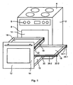
- the in Fig. 1 oven 2 shown according to the invention contains on its upper side a hob 4 (or a cooktop) and on its front panel controls above 6. Below is the muffle opening 8 of a baking oven muffle 10.
- a baking tray 12 is designed for retraction and extension into the oven muffle 10 for which purpose guide elements are provided in the baking oven muffle 10 and on the baking tray 12, for example a telescopic device which is not shown in detail here.
- the baking tray is provided behind the front wall 14 with at least one carrying device 15 for carrying and transverse process of at least one food support 18 from a parking position behind the front wall 14 and a transverse offset position, in which the food support 18 protrudes laterally at least partially over the front wall 14.
- Fig. 1 shows in two superimposed floors depending such a support device 15th
- the support device 15 includes a support frame 16, as in Fig. 2 is shown.
- the support frame 16 is not mounted on a floor or other support structure, but on the back of the front wall 14. According to the preferred embodiment shown are at the back of the Front wall 14 hook rails 20 attached to which the support frame 16 is suspended and is then held cantilevered.
- the food support 18 is for example a baking sheet or a grill or other device for carrying or holding food (food of any kind).
- the front wall may contain a viewing window made of glass or transparent plastic as known oven doors or consist entirely of such a material.
- the carrying device 15 has a telescopic device 22 arranged in the carriage transverse direction, which has a stationary telescopic part 24 mounted behind the front wall in the parking position on the supporting frame 16 and a transverse carriage offset from the parking position laterally beyond the front wall 14 into the transverse offset position movable telescopic part 26 has.
- the movable telescopic part 26 is designed to receive a food support 18.
- the movable telescopic part 26 is provided with fixing parts 30, 31, 32, and 33 for fixing the food support 18 in order to limit or block relative movements between the movable telescope part 26 and the food support 18 at least in the carriage transverse direction. This not only avoids that the food support 18 inadvertently can slide down from the movable telescopic part 26, but also achieves the advantage that the movable telescopic part 26 is movable relative to the fixed telescopic part 24 by a force acting on the food support 18 force of a user person transverse to the baking tray without the movable telescope part 26 needing to be touched by the user person.
- fixing parts 30, 31, 32 and 33 can bends of the movable telescopic part 26 or attached thereto, for. B. be welded or bolted elements, such as locating bolts.
- Fig. 2 shows four such locating bolts 30, 31, 32 and 33, wherein one is located at each corner of the food support 18. An edge region of the food support 18 rests on the locating bolt and a recessed depression area located within the edge region engages behind the locating bolts.
- According to another embodiment can be formed in the food support 18 receiving holes through which the receiving bolt can protrude through.
- the two telescopic parts 24 and 26 may be plate-like body, one of which is arranged in the other and is displaceable relative to each other in the carriage transverse direction.
- a significantly lighter in weight, yet sturdy construction is that the telescopic device 22 has at least two telescopes 22-1 and 22-2 arranged parallel next to each other in the transverse direction of the wagon, each having a stationary telescopic rod 24-1 or fastened to the baking tray 12 in the parking position or fixable 24-2 and a telescopic rod 26-1 and 26-2 movable relative to the latter in the longitudinal direction of the rod, the stationary telescopic rod 24-1 and 24-2 belonging to the fixed telescopic part 24 and the movable telescopic rod 26-1 and 26-2 belongs to the movable telescopic part 26 and is designed to receive the food support 18.
- the telescopic rods may be rails or tubes.
- Each telescope 22-1 and 22-2 may have two or more movable telescopic rods instead of a single movable telescopic rod 26-1 and 26-2, respectively, which are movable relative to each other in the bar longitudinal direction to a food support 18 in a partial or preferably completely adjacent to the Front wall 14 location to move transverse offset position.
- the food support 18 is located here on the most extendable telescopic poles.
- rolling bearings 34 are arranged, on which roll the movable telescopic poles ,
- Rolling bearings can be ball bearings, roller bearings, tapered bearings or similar bearings.
- Fig. 3 of the drawings shows in a side view in the direction of an arrow III of Fig. 2
- Bearing balls 36 which are arranged in bearing cages between a stationary telescopic rod 24-1 and a relative to it in rod longitudinal direction movable telescopic rod 26-1.
- the fixing parts or receiving bolts 30, 31, 32 and 33 prevent the movable telescopic rods 26-1 and 26-2 from being displaceable relative to one another in the longitudinal direction of the rod when a food support 18 is located on them.
- the connecting element 40 is preferably located at the end of the movable telescopic rods 26-1 and 26-2 remote from the fixed telescopic rods 24-1 and 24-2. At this point, it is most easily grasped by a user person to move the movable telescope part 26 relative to the fixed telescopic part 24.
- At least one detent device 42 is provided, the locking force of which can be overcome by acting on the movable telescopic part 26 in the transverse direction of the car manual operating force.
- the detent device 42 may be provided at the front end adjacent the front wall 14 and / or at the rear end of the telescopic device 22.
- the detent device 42 may comprise a bolt which is supported by a spring, e.g. B. a leaf spring or coil spring, is pushed in the trailer longitudinal direction and can engage behind a latching surface, one of the two parts bolt or locking surface on the movable telescopic part 26 and the other part is arranged on a stationary part of the back carriage, for example, on the stationary telescopic part 24th or on the support frame 16 carrying it.
- the detent device 42 is designed such that a user person can feel the latching action on the movable telescopic part 26 or the food support 18 located thereon by a small vibration.
- the detent device 42 should hold the movable telescopic part 26 safely even in the parking position when it shakes so that it does not move laterally out of the baking tray. At the same time, the detent device 42 should be designed such that only a small force is required by a user to disengage the movable telescopic part 26 on the detent device 42 and to move it from the park position transversely out of the baking tray.
- each detent device 42 has at least one longitudinally extending in the transverse direction, longitudinally flexible in the carriage longitudinally elastic spring element 44, on which at least one detent surface is formed, and a detent element 54 for locking on the detent surface.
- spring element 44 and detent element 54 of the one part on the stationary telescopic part 26 or its support frame 16 and the other part is formed or fixed to the movable telescopic part 26.
- two spring elements 44 are arranged fixed behind the front wall 14 and two associated latching elements 54 are arranged on the movable telescopic part 26.
- the elongated spring element 44 is a leaf spring strip or preferably correspondingly Fig.
- the detent element 54 is a bolt formed or fastened to the movable telescopic part 26, which extends transversely to the shafts 48, 50, 52 of the spring element 44, whose wave peaks 48 and 50 lie in the path of movement of the detent element 54.
- the detent element 54 slides over one of the two wave peaks 42 into the wave trough 52, the detent element 54 on the wave crest 48 or 50 pushing away the spring element laterally and then entering the wave trough 52 of the spring element 44 that springs back.
- the movable telescopic part 26 can be pushed out from the parking position behind the front wall 14 selectively in one direction or in the other direction transversely out of the baking tray.
- the detent element 54 slides over the one wave crest 48, in the other direction of movement the detent element 54 slides over the other crest 50, thereby pushing the spring element 44 out of the path of movement of the detent element 54.
- the elongate spring element or spring steel wire 44 is preferably not only at one end, but both ends at a distance from the waveform 48, 50, 52 attached to the fixed telescopic part 24 or the support frame 16. As a result, in contrast to a spring element 44, which is attached only at one end, an unintentional bending of the spring element and thus a decrease in the spring force on the detent element 54 is avoided.
- Fig. 4 shows in an enlarged scale relative to the other figures, the movable telescopic part 26 with the detent element 54 formed on it or fastened and the elongated spring element 44 when the movable telescopic part 26 is located in the parking position in the center behind the front wall 14 and thereby the detent element 54 in the Wellental 52 between the two wave crests 48 and 50 is engaged. Further shows Fig. 4 by arrows 60 and 62 that the movable telescopic part 26 is displaceable in both the one arrow direction 60 and in the other direction of arrow 62 from the parking position into a transverse offset position relative to the baking tray.
- the detent element 54 (bolt) slides over the one corrugation peak 48 or the other corrugation peak 50, wherein the corrugation peak and thus the spring element 44 is pushed away in the direction of arrow 64.
- the spring element returns to a neutral position by means of its spring force in accordance with an arrow 66.
- Fig. 4 is the spring in the region of the corrugation 48, 50, 52 as far as the side bent against the movable telescopic part 26 that the trough 52 is biased against the detent element 54 with resilient bias.
Landscapes
- Engineering & Computer Science (AREA)
- Chemical & Material Sciences (AREA)
- Combustion & Propulsion (AREA)
- Mechanical Engineering (AREA)
- General Engineering & Computer Science (AREA)
- Baking, Grill, Roasting (AREA)
- Handcart (AREA)
- Meat, Egg Or Seafood Products (AREA)
- Drying Of Solid Materials (AREA)
- Electric Ovens (AREA)
Description
- Die Erfindung betrifft einen Backwagen gemäß dem Oberbegriff von Anspruch 1. Ein solcher Backwagen ist aus Dokument
DE-U-9 406 630 schon bekannt. Ferner betrifft die Erfindung einen Backofen mit einem solchen Backwagen. Aus derDE 19 817 499 C1 ist ein Backofen mit einer Vorrichtung zur Auflage von Gargutträgern bekannt. DieDE 19 949 239 A1 zeigt eine Auszugsvorrichtung für Gargutträger im Garraum von Garöfen. - Demgemäß betrifft die Erfindung einen Backofen und einen Backofen-Wagen, welcher zum Ein- und Ausfahren in einer Backofenmuffel ausgebildet ist und folgende Merkmale aufweist: eine Frontwand als Backofentür zum Verschließen der Backofenmuffel; mindestens eine Tragvorrichtung hinter der Frontwand zum Tragen und Querverfahren von mindestens einem Gargutträger von einer Parkposition hinter der Backofentür und einer Querversatzposition, bei welcher der Gargutträger mindestens teilweise über die Backofentür seitlich hinausragt.
- Beim Stand der Technik eines solchen Backofens gleitet das Backblech direkt auf einem Drahtrahmen, welcher in Hakenschienen eingehängt ist. Die Hakenschienen sind an der Rückseite einer Frontwand des Backwagens befestigt. Das Backblech kann sowohl nach rechts als auch nach links herausgezogen werden. Das Backblech ist gegen Abkippen nur schlecht gesichert. Sein Auszugsweg nach links oder nach rechts ist daher auf ungefähr drei Viertel der Backblechbreite beschränkt. Backöfen dieser Art sind aus der DE-Gebrauchsmusterschrift G 94 06 630.2 und aus der
DE-A-39 24 588 bekannt. - Ferner sind aus der
DE 36 28 763 C2 undDE 198 17 499 C1 Backöfen mit Teleskopauszügen in der Backofenmuffel bekannt. Teleskopauszüge sind nach vorne aus der Backofenmuffel herausziehbar und darin wieder einschiebbar. - Durch die Erfindung soll die Aufgabe gelöst werden, bei einem Backofen mit einem Backwagen, welcher in der Backofenmuffel einfahrbar und ausfahrbar angeordnet ist, einen besseren Benutzungskomfort zu erzielen. Ferner soll der Gargutträger aus dem Backwagen seitlich ausziehbar sein, ohne abzukippen.
- Diese Aufgabe wird gemäß der Erfindung durch Patentanspruch 1 gelöst.
- Der Gargutträger gleitet hierbei nicht auf der Tragvorrichtung, sondern er sitzt auf einem ausziehbaren Teleskopteil der Tragvorrichtung.
- Die Erfindung hat folgende Vorteile: bessere Sicherung des Gargutträgers gegen Abkippen in der seitlich aus dem Backwagen herausragenden Querversatzposition; die Möglichkeit, den Querversatzweg größer als beim Stand der Technik zu machen, um die Belegung des Gargutträgers mit Gargut für die Benutzerperson zu erleichtern; Reduzierung der zur Bewegung des Gargutträgers quer zum Backwagen erforderlichen Verschiebekraft; die Möglichkeit der Schaffung einer komfortablen Rastensicherung zum Halten des Gargutträgers in der Parkposition; Ausziehbarkeit des beweglichen Teleskopteiles mit dem Gargutträger sowohl nach rechts als auch nach links aus dem Backwagen heraus in eine Querversatzposition, ohne auf die vorgenannten Vorteile verzichten zu müssen. Damit ergibt sich eine wesentliche Komfortverbesserung gegenüber dem Stand der Technik; bereits bestehende Backöfen und Backwagen können auf einfache Weise mit geringem Kostenaufwand mit der Erfindung versehen werden; ein Vollauszug, bei welchem der Gargutträger aus dem Backwagen in eine vollständig neben der Frontwand gelegene Querversatzposition ausziehbar ist ist mit geringem Aufwand realisierbar.
- Weitere Merkmale der Erfindung sind in den Unteransprüchen enthalten.
- Die Erfindung wird im folgenden mit Bezug auf die Zeichnungen anhand von bevorzugten Ausführungsformen als Beispiele beschrieben. In den Zeichnungen zeigen
- Fig.
- 1 schematisch einen Backofen gemäß der Erfindung,
- Fig. 2
- schematisch einen Teil eines Backofen-Backwagens von
Fig. 1 , - Fig. 3
- ein Detail von
Fig. 2 , - Fig. 4
- ein weiteres Detail von
Fig. 2 . - Der in
Fig. 1 gezeigte Backofen 2 nach der Erfindung enthält auf seiner Oberseite ein Kochfeld 4 (oder eine Kochmulde) und auf seiner Frontseite oben Bedienelemente 6. Darunter befindet sich die Muffelöffnung 8 einer Backofenmuffel 10. Ein Backwagen 12 ist zum Ein- und Ausfahren in die Backofenmuffel 10 ausgebildet, zu welchem Zwecke in der Backofenmuffel 10 und am Backwagen 12 Führungselemente vorgesehen sind, beispielsweise eine Teleskopvorrichtung, welche hier nicht im Detail gezeigt ist. - Eine Frontwand 14 des Backwagens 12 bildet eine Backofentür zum Verschließen der Muffelöffnung 8. Der Backwagen ist hinter der Frontwand 14 mit mindestens einer Tragvorrichtung 15 zum Tragen und Querverfahren von mindestens einem Gargutträger 18 von einer Parkposition hinter der Frontwand 14 und einer Querversatzposition versehen, bei welcher der Gargutträger 18 mindestens teilweise über die Frontwand 14 seitlich hinausragt.
Fig. 1 zeigt in zwei übereinanderliegenden Etagen je eine solche Tragvorrichtung 15. - Die Tragvorrichtung 15 enthält einen Tragrahmen 16, wie er in
Fig. 2 gezeigt ist. Der Tragrahmen 16 ist nicht auf einem Boden oder einer anderen Stützkonstruktion, sondern an der Rückseite der Frontwand 14 befestigt. Gemäß der gezeigten bevorzugten Ausführungsform sind an der Rückseite der Frontwand 14 Hakenschienen 20 befestigt, an welchen der Tragrahmen 16 einhängbar ist und dann freitragend gehalten wird. - Der Gargutträger 18 ist beispielsweise ein Backblech oder ein Grillrost oder eine andere Vorrichtung zum Tragen oder Halten von Gargut (Speisen jeder Art).
- Die Frontwand kann wie bekannte Backofentüren ein Sichtfenster aus Glas oder durchsichtigem Kunststoff enthalten oder insgesamt aus einem solchen Material bestehen.
- Die Tragvorrichtung 15 weist eine in Wagenquerrichtung angeordnete Teleskopvorrichtung 22 auf, welche einen im Backwagen 12 hinter der Frontwand in der Parkposition am Tragrahmen 16 befestigten oder befestigbaren ortsfesten Teleskopteil 24 und einen relativ dazu in Wagenquerrichtung von der Parkposition seitlich über die Frontwand 14 hinaus in die Querversatzposition bewegbaren Teleskopteil 26 hat. Der bewegbare Teleskopteil 26 ist zur Aufnahme eines Gargutträgers 18 ausgebildet.
- Der bewegliche Teleskopteil 26 ist mit Fixierteilen 30, 31, 32, und 33 zur Fixierung des Gargutträgers 18 versehen, um Relativbewegungen zwischen dem beweglichen Teleskopteil 26 und dem Gargutträger 18 mindestens in Wagenquerrichtung zu begrenzen oder zu sperren. Damit wird nicht nur vermieden, dass der Gargutträger 18 unbeabsichtigt vom beweglichen Teleskopteil 26 herunter rutschen kann, sondern auch der Vorteil erzielt, dass der bewegliche Teleskopteil 26 durch eine auf den Gargutträger 18 wirkende Kraft einer Benutzerperson quer zum Backwagen relativ zum feststehenden Teleskopteil 24 bewegbar ist, ohne dass der bewegliche Teleskopteil 26 von der Benutzerperson berührt zu werden braucht.
- Diese Fixierteile 30, 31, 32 und 33 können Abwinkelungen des beweglichen Teleskopteiles 26 oder daran befestigte, z. B. angeschweißte oder angeschraubte Elemente sein, beispielsweise Aufnahmebolzen.
Fig. 2 zeigt vier solcher Aufnahmebolzen 30, 31, 32 und 33, wobei sich je einer an jedem Eck des Gargutträgers 18 befindet. Ein Randbereich des Gargutträgers 18 liegt auf den Aufnahmebolzen auf und ein innerhalb des Randbereiches gelegener vertiefter Muldenbereich greift hinter die Aufnahmebolzen. Gemäß einer anderen Ausführungsform können im Gargutträger 18 Aufnahmelöcher gebildet sein, durch welche die Aufnahmebolzen hindurch ragen können. - Die beiden Teleskopteile 24 und 26 können plattenartige Körper sein, von welchen der eine im anderen angeordnet ist und relativ zueinander in Wagenquerrichtung verschiebbar ist. Eine gewichtsmäßig wesentlich leichtere und trotzdem stabile Konstruktion besteht darin, dass die Teleskopvorrichtung 22 mindestens zwei in Wagenquerrichtung parallel nebeneinander angeordnete Teleskope 22-1 und 22-2 aufweist, die je eine am Backwagen 12 in der Parkposition befestigte oder befestigbare ortsfeste Teleskopstange 24-1 bzw. 24-2 und eine relativ zu dieser in Stangenlängsrichtung bewegbare Teleskopstange 26-1 bzw. 26-2 aufweisen, wobei die ortsfeste Teleskopstange 24-1 und 24-2 zum ortsfesten Teleskopteil 24 gehört und die bewegliche Teleskopstange 26-1 und 26-2 zum beweglichen Teleskopteil 26 gehört und zur Aufnahme des Gargutträgers 18 ausgebildet ist. Die Teleskopstangen können Profilschienen oder Rohre sein.
- Jedes Teleskop 22-1 und 22-2 kann anstelle einer einzigen bewegbaren Teleskopstange 26-1 bzw. 26-2 zwei oder mehr bewegbare Teleskopstangen haben, die relativ zueinander in Stangenlängsrichtung bewegbar sind, um einen Gargutträger 18 in eine teilweise oder vorzugsweise vollständig neben der Frontwand 14 gelegene Querversatzposition bewegen zu können. Der Gargutträger 18 befindet sich hierbei auf den am weitesten ausfahrbaren Teleskopstangen.
- Gemäß der bevorzugten Ausführungsform der Erfindung sind zwischen den Teleskopstangen 24-1 und 26-1 des einen Teleskops 22-1 und zwischen den Teleskopstangen 24-2 und 26-2 des anderen Teleskops 22-2 Wälzlager 34 angeordnet, auf welchen die beweglichen Teleskopstangen rollen. Wälzlager können Kugellager, Rollenlager, Kegellager oder ähnliche Lager sein.
Fig. 3 der Zeichnungen zeigt in einer Seitenansicht in Richtung eines Pfeiles III vonFig. 2 gesehen Lagerkugeln 36, welche in Lagerkäfigen zwischen einer ortsfesten Teleskopstange 24-1 und einer relativ zu ihr in Stangenlängsrichtung beweglichen Teleskopstange 26-1 angeordnet sind. Dadurch wird ein Verklemmen der Teleskopstangen relativ zueinander verhindert und sie sind mit geringerer Kraft relativ zueinander leicht verschiebbar. - Die Fixierteile oder Aufnahmebolzen 30, 31, 32 und 33 verhindern, dass sich die beweglichen Teleskopstangen 26-1 und 26-2 in Stangenlängsrichtung relativ zueinander verschieben können, wenn sich auf ihnen ein Gargutträger 18 befindet. Um eine solche Relatiwerschiebung der beweglichen Teleskopstangen 26-1 und 26-2 relativ zueinander auch dann zu verhindern, wenn sie keinen Gargutträger 18 tragen, ist es vorteilhaft, wenn sie durch mindestens ein Verbindungselement 40 miteinander verbunden sind, so dass sie auch ohne Gargutträger 18 nur gemeinsam relativ zu den ortsfesten Teleskopstangen 24-1 und 24-2 beweglich sind. Das Verbindungselement 40 befindet sich vorzugsweise an dem von den ortsfesten Teleskopstangen 24-1 und 24-2 entfernten Ende der beweglichen Teleskopstangen 26-1 und 26-2. An dieser Stelle ist es von einer Benutzerperson am einfachsten greifbar, um den beweglichen Teleskopteil 26 relativ zum ortsfesten Teleskopteil 24 zu bewegen.
- Zur automatischen Arretierung des beweglichen Teleskopteils 26 in der Parkposition ist mindestens eine Rastenvorrichtung 42 vorgesehen, deren Arretierkraft durch eine auf den beweglichen Teleskopteil 26 in Wagenquerrichtung wirkende manuelle Betätigungskraft überwindbar ist.
- Die Rastenvorrichtung 42 kann am vorderen, der Frontwand 14 benachbarten Ende und/oder am hinteren Ende der Teleskopvorrichtung 22 vorgesehen sein. Die Rastenvorrichtung 42 kann einen Bolzen aufweisen, welcher von einer Feder, z. B. einer Blattfeder oder Schraubenfeder, in Backwagenlängsrichtung gedrängt wird und hinter einer Einrastfläche einrasten kann, wobei einer der beiden Teile Bolzen oder Einrastfläche am beweglichen Teleskopteil 26 und der betreffende andere Teil an einem ortsfesten Teil des Backwagens angeordnet ist, beispielsweise an dem ortsfesten Teleskopteil 24 oder an dem ihn tragenden Tragrahmen16. Die Rastenvorrichtung 42 ist derart ausgebildet, dass eine Benutzerperson den Einrastvorgang an dem bewegbaren Teleskopteil 26 oder dem darauf liegenden Gargutträger 18 durch eine kleine Erschütterung spüren kann. Die Rastenvorrichtung 42 sollte den bewegbaren Teleskopteil 26 auch bei Erschütterungen in der Parkposition sicher halten, damit er nicht seitlich aus dem Backwagen sich herausbewegt. Gleichzeitig sollte die Rastenvorrichtung 42 derart ausgebildet sein, dass von einer Benutzerperson nur eine geringe Kraft erforderlich ist, um den beweglichen Teleskopteil 26 an der Rastenvorrichtung 42 auszurasten und von der Parkposition quer aus dem Backwagen heraus zu bewegen.
- Gemäß der bevorzugten Ausführungsform der Erfindung hat jede Rastenvorrichtung 42 mindestens ein sich in Wagenquerrichtung erstreckendes, in Wagenlängsrichtung federelastisch biegsames, längliches Federelement 44, an welchem mindestens eine Rastfläche gebildet ist, und ein Rastenelement 54 zum Einrasten an der Rastenfläche. Von den beiden Teilen Federelement 44 und Rastenelement 54 ist der eine Teil am ortsfesten Teleskopteil 26 oder dessen Tragrahmen 16 und der andere Teil am beweglichen Teleskopteil 26 geformt oder befestigt ist. Bei der Ausführungsform von
Fig. 2 sind zwei Federelemente 44 hinter der Frontwand 14 ortsfest angeordnet und zwei ihnen zugeordnete Rastenelemente 54 sind an dem beweglichen Teleskopteil 26 angeordnet. Das längliche Federelement 44 ist ein Blattfederstreifen oder vorzugsweise entsprechendFig. 2 ein Federstahldraht, an welchem durch eine Profilierung oder wellenförmige Verformung ein Wellental 52 zwischen zwei Wellenbergen 48 und 50 gebildet ist, so dass die einander benachbarten Bergflächen im Wellental 52 je eine Rastfläche bilden, zwischen welchen das Rastenelement 54 einrastbar ist. Das Rastenelement 54 ist ein am beweglichen Teleskopteil 26 gebildeter oder befestigter Bolzen, der sich quer zu den Wellen 48, 50, 52 des Federelements 44 erstreckt, dessen Wellenberge 48 und 50 im Bewegungsweg des Rastenelements 54 liegen. Dadurch gleitet das Rastenelement 54 über einen der beiden Wellenberge 42 hinweg in das Wellental 52, wobei das Rastenelement 54 auf dem Wellenberg 48 oder 50 das Federelement seitlich wegdrückt und dann in das Wellental 52 des zurückfedernden Federelements 44 gelangt. - Gemäß der Erfindung ist der bewegbare Teleskopteil 26 von der Parkposition hinter der Frontwand 14 wahlweise in der einen Richtung oder in der anderen Richtung quer aus dem Backwagen herausschiebbar. In der einen Richtung gleitet das Rastenelement 54 über den einen Wellenberg 48, in der anderen Bewegungsrichtung gleitet das Rastenelement 54 über den anderen Wellenberg 50, und drückt dabei das Federelement 44 aus der Bewegungsbahn des Rastenelements 54.
- Das längliche Federelement bzw. Federstahldraht 44 ist vorzugsweise nicht nur an einem Ende, sondern beiden Enden mit Abstand von der Wellenform 48, 50, 52 an dem ortsfesten Teleskopteil 24 oder dessen Tragrahmen 16 befestigt. Dadurch wird im Gegensatz zu einem Federelement 44, welches nur an einem Ende befestigt ist, ein unbeabsichtigtes Verbiegen des Federelements und damit ein Nachlassen der Federkraft auf das Rastenelement 54 vermieden.
-
Fig. 4 zeigt in einem gegenüber den anderen Figuren vergrößerten Maßstab den beweglichen Teleskopteil 26 mit dem an ihm gebildeten oder befestigten Rastenelement 54 und das längliche Federelement 44, wenn sich der bewegliche Teleskopteil 26 in der Parkposition mittig hinter der Frontwand 14 befindet und dabei das Rastenelement 54 in das Wellental 52 zwischen den beiden Wellenbergen 48 und 50 eingerastet ist. Ferner zeigtFig. 4 durch Pfeile 60 und 62, dass der bewegliche Teleskopteil 26 sowohl in der einen Pfeilrichtung 60 als auch in der anderen Pfeilrichtung 62 von der Parkposition in eine Querversatzposition relativ zum Backwagen verschiebbar ist. Hierbei gleitet das Rastenelement 54 (Bolzen) über den einen Wellenberg 48 oder den anderen Wellenberg 50 hinweg, wobei der Wellenberg und damit das Federelement 44 in Pfeilrichtung 64 weggedrückt wird. Wenn das Rastenelement 54 den einen oder anderen Wellenberg 48 bzw. 50 verläßt, kehrt das Federelement durch seine Federkraft entsprechend einem Pfeil 66 in eine Neutralstellung zurück. GemäßFig. 4 ist die Feder im Bereich der Wellung 48, 50, 52 soweit seitlich gegen den bewegbaren Teleskopteil 26 gebogen, dass das Wellental 52 mit federelastischer Vorspannung gegen das Rastenelement 54 gespannt ist.
Claims (11)
- Backwagen mit einer Frontwand (14) als Backofentür zum Verschließen einer Backofenmuffel (10) und mindestens einer Tragvorrichtung (15) hinter der Frontwand (14) zum Tragen und Querverfahren von mindestens einem Gargutträger (18) von einer Parkposition hinter der Frontwand (14) in eine Querversatzposition, bei welcher der Gargutträger mindestens teilweise über die Frontwand (14) seitlich hinausragt, und welche Tragvorrichtung (15) eine in Wagenquerrichtung angeordnete Teleskopvorrichtung (22) aufweist, welche einen ortsfesten Teleskopteil (24) und mindestens einen relativ dazu in Wagenquerrichtung von der Parkposition seitlich über die Frontwand (14) hinaus in die Querversatzposition bewegbaren Teleskopteil (26) aufweist, welcher zur Aufnahme des Gargutträgers (18) ausgebildet ist, dadurch gekennzeichnet, dass die Teleskopvorrichtung (22) mindestens zwei in Wagenquerrichtung parallel nebeneinander angeordnete Teleskope (22-1, 22-2) aufweist, die eine am Backwagen in der Parkposition befestigte oder befestigbare ortsfeste Teleskopstange (24-1, 24-2) und eine relativ zu dieser in Stangenlängsrichtung bewegbare Teleskopstange (26-1, 26-2) aufweisen, wobei die ortsfeste Teleskopstange (24-1, 24-2) zum ortsfesten Teleskopteil (24) gehört und die bewegliche Teleskopstange (26-1, 26-2) zum beweglichen Teleskopteil (26) gehört und zur Aufnahme des Gargutträgers (18) ausgebildet ist, welcher bewegliche Teleskopteil (26) relativ zum ortsfesten Teleskopteil (24) von der Parkposition aus wahlweise in der einen oder in der anderen Wagenquerrichtung in eine Querversatzposition aus dem Backwagen heraus bewegbar ist, bei welcher der bewegliche Teleskopteil mindestens teilweise seitlich über die Frontwand (14) hinausragt, und dass die Tragvorrichtung (15) einen Tragrahmen (16) aufweist, an welchem die ortsfesten Teleskopstangen (24-1, 24-2) befestigt sind und welcher an der Rückseite der Frontwand (14) befestigt oder befestigbar ist.
- Backwagen nach Anspruch 1, dadurch gekennzeichnet, dass der bewegliche Teleskopteil Fixierteile (30, 31, 32, 33) zur Fixierung des Gargutträgers (18) aufweist, um Relativbewegungen zwischen dem beweglichen Teleskopteil (26) und dem Gargutträger (18) mindestens in Wagenquerrichtung zu begrenzen oder zu sperren.
- Backwagen nach einem der vorhergehenden Ansprüche, dadurch gekennzeichnet, dass zwischen den Teleskopstangen (24-1, 26-1; 24-2, 26-2) Wälzlager angeordnet sind, auf welchen die beweglichen Teleskopstangen (26-1, 26-2) rollen.
- Backwagen nach mindestens einem der Ansprüche 2 oder 3, dadurch gekennzeichnet, dass die Fixierteile (30, 31, 32, 33) Bolzen sind, an welchen der Gargutträger (18) positionierbar ist.
- Backwagen nach mindestens einem der vorhergehenden Ansprüche, dadurch gekennzeichnet, dass die beweglichen Teleskopstangen (26-1, 26-2) durch mindestens ein Verbindungselement (40) miteinander verbunden sind, so dass sie nur gemeinsam relativ zu den ortsfesten Teleskopstangen (24-1, 24-2) beweglich sind.
- Backwagen nach mindestens einem der vorhergehenden Ansprüche, dadurch gekennzeichnet, dass mindestens eine Rastenvorrichtung (42) vorgesehen ist, durch welche der bewegliche Teleskopteil (26) in der Parkposition arretierbar ist.
- Backwagen nach Anspruch 6, dadurch gekennzeichnet, dass der bewegliche Teleskopteil (26) durch eine auf ihn in Wagenquerrichtung ausgeübte Kraft einer Benutzerperson an der Rastenvorrichtung (42) ausrastbar ist, um von der Parkposition in Richtung zur Querversatzposition bewegt zu werden.
- Backwagen nach Anspruch 6 oder 7, dadurch gekennzeichnet, dass die mindestens eine Rastenvorrichtung (42) mindestens ein sich in Wagenquerrichtung erstreckendes, in Wagenlängsrichtung federelastisch biegsames, längliches Federelement (44) mit mindestens einer Rastenfläche (48, 50, 52 aufweist, an welcher ein Rastenelement (54) einrastbar ist, wobei von den beiden Teilen Federelement (44) und Rastenelement (54) der eine Teil ortsfest angeordnet ist und der andere Teil am beweglichen Teleskopteil (26) vorgesehen ist.
- Backwagen nach Anspruch 8, dadurch gekennzeichnet, dass das Federelement (44) ortsfest angeordnet ist und das Rastenelement (54) am beweglichen Teleskopteil (26) vorgesehen ist.
- Backwagen nach mindestens einem der vorhergehenden Ansprüche, dadurch gekennzeichnet, dass die Rückseite der Frontwand (14) eine Hakenvorrichtung (20) aufweist, an welcher die Tragvorrichtung (15) einhängbar ist.
- Backofen, gekennzeichnet durch einen Backwagen gemäß mindestens einem der vorhergehenden Ansprüche.
Applications Claiming Priority (2)
| Application Number | Priority Date | Filing Date | Title |
|---|---|---|---|
| DE10211519 | 2002-03-15 | ||
| DE10211519A DE10211519A1 (de) | 2002-03-15 | 2002-03-15 | Backofen und Backwagen |
Publications (4)
| Publication Number | Publication Date |
|---|---|
| EP1344985A2 EP1344985A2 (de) | 2003-09-17 |
| EP1344985A3 EP1344985A3 (de) | 2006-08-23 |
| EP1344985B1 EP1344985B1 (de) | 2007-11-14 |
| EP1344985B2 true EP1344985B2 (de) | 2011-10-26 |
Family
ID=27762935
Family Applications (1)
| Application Number | Title | Priority Date | Filing Date |
|---|---|---|---|
| EP03005542A Expired - Lifetime EP1344985B2 (de) | 2002-03-15 | 2003-03-11 | Backofen und Backwagen |
Country Status (4)
| Country | Link |
|---|---|
| EP (1) | EP1344985B2 (de) |
| AT (1) | ATE378555T1 (de) |
| DE (2) | DE10211519A1 (de) |
| ES (1) | ES2295476T5 (de) |
Cited By (1)
| Publication number | Priority date | Publication date | Assignee | Title |
|---|---|---|---|---|
| DE102015108806A1 (de) | 2015-06-03 | 2016-12-08 | Miele & Cie. Kg | Elektroherd mit einem Backwagen |
Families Citing this family (17)
| Publication number | Priority date | Publication date | Assignee | Title |
|---|---|---|---|---|
| DE102004031724B4 (de) * | 2004-06-30 | 2018-10-31 | BSH Hausgeräte GmbH | Auszugssystem für Haushaltsgeräte |
| DE102004031723A1 (de) * | 2004-06-30 | 2006-01-26 | BSH Bosch und Siemens Hausgeräte GmbH | Auszugsystem |
| DE102005019956A1 (de) * | 2005-04-29 | 2006-11-02 | Electrolux Home Products Corporation N.V. | Garofenmuffel |
| ES2284331B1 (es) * | 2005-06-15 | 2009-01-01 | Bsh Electrodomesticos España, S.A. | Aparato electrodomestico. |
| ATE456008T1 (de) | 2007-11-26 | 2010-02-15 | Electrolux Home Prod Corp | Selbstreinigender backofen |
| EP2090832B1 (de) | 2008-02-15 | 2013-06-12 | Electrolux Home Products Corporation N.V. | Türensystem zur Schließung einer Zufuhrvorrichtung zum Garraum eines Backofens |
| DE202008010190U1 (de) * | 2008-07-30 | 2009-12-10 | Paul Hettich Gmbh & Co. Kg | Auszugsvorrichtung für ein Haushaltsgerät |
| WO2010076142A2 (en) * | 2008-12-29 | 2010-07-08 | Arcelik Anonim Sirketi | An oven with telescopic rails |
| DE202011105786U1 (de) | 2011-09-16 | 2012-12-17 | Hörauf & Kohler Verwaltungs KG | Rotationsdämpfer mit Freilauf |
| DE102011113617A1 (de) | 2011-09-16 | 2013-03-21 | Hörauf & Kohler Verwaltungs KG | Rotationsdämpfer mit Freilauf |
| CA2867330A1 (en) * | 2012-03-28 | 2013-10-03 | B/E Aerospace, Inc. | Oven having slidable drawer mechanism |
| DE202012104877U1 (de) * | 2012-12-14 | 2013-01-31 | Hans Giesbert Gmbh & Co. Kg | Teleskopierbarer Schienenauszug für einen schubladenartigen Geräte- oder Möbelkorpus |
| DE202018100849U1 (de) * | 2018-02-15 | 2018-05-02 | Accente Limited | Grill |
| DE202018106399U1 (de) * | 2018-11-12 | 2020-02-13 | Grass Gmbh | Führungsvorrichtung zur Führung eines Gutträgers in einem Gehäuse |
| DE102023109292A1 (de) | 2023-04-13 | 2024-10-17 | Illinois Tool Works Inc. | Rotationsdämpfer zum reduzieren und insbesondere bremsen einer dreh- oder schwenkbewegung eines relativ zu einem ersten bauteil drehbaren zweiten bauteils |
| DE102023005415A1 (de) | 2023-04-13 | 2024-10-17 | Illinois Tool Works Inc. | Rotationsdämpfer zum reduzieren und insbesondere bremsen einer dreh- oder schwenkbewegung eines relativ zu einem ersten bauteil drehbaren zweiten bauteils |
| EP4545863B1 (de) * | 2023-10-23 | 2026-04-29 | Miele & Cie. KG | Gargerät und verfahren zum betreiben |
Citations (6)
| Publication number | Priority date | Publication date | Assignee | Title |
|---|---|---|---|---|
| DE7507245U (de) † | 1974-04-02 | 1975-08-07 | De Dietrich & Cie | Herausziehbare unterlage fuer herd und einbaubackoefen o dgl |
| DE3924588A1 (de) † | 1989-07-25 | 1991-01-31 | Bosch Siemens Hausgeraete | Backofen |
| DE3628763C2 (de) † | 1986-08-25 | 1993-02-04 | Bosch-Siemens Hausgeraete Gmbh, 8000 Muenchen, De | |
| DE4106809C2 (de) † | 1991-03-04 | 1994-10-27 | Huwil Werke Gmbh | Führung für ein Schubfach |
| DE19817499C1 (de) † | 1998-04-20 | 1999-12-09 | Bsh Bosch Siemens Hausgeraete | Backofen mit Teleskopauszug |
| DE19949239A1 (de) † | 1999-10-13 | 2001-04-26 | Aeg Hausgeraete Gmbh | Auszugsvorrichtung für Gargutträger im Garraum von Garöfen |
Family Cites Families (3)
| Publication number | Priority date | Publication date | Assignee | Title |
|---|---|---|---|---|
| DE9406630U1 (de) * | 1994-04-20 | 1994-06-23 | Bosch-Siemens Hausgeräte GmbH, 81669 München | Backofen mit einer schubkastenartig geführten Ofentür |
| DE4444316C2 (de) * | 1994-12-13 | 1999-08-05 | Bosch Siemens Hausgeraete | Herd |
| DE20210598U1 (de) * | 2002-07-09 | 2002-09-05 | Moll System- und Funktionsmöbel GmbH, 73344 Gruibingen | Vorrichtung zum Führen einer Schublade |
-
2002
- 2002-03-15 DE DE10211519A patent/DE10211519A1/de not_active Withdrawn
-
2003
- 2003-03-11 EP EP03005542A patent/EP1344985B2/de not_active Expired - Lifetime
- 2003-03-11 DE DE50308571T patent/DE50308571D1/de not_active Expired - Lifetime
- 2003-03-11 ES ES03005542T patent/ES2295476T5/es not_active Expired - Lifetime
- 2003-03-11 AT AT03005542T patent/ATE378555T1/de not_active IP Right Cessation
Patent Citations (6)
| Publication number | Priority date | Publication date | Assignee | Title |
|---|---|---|---|---|
| DE7507245U (de) † | 1974-04-02 | 1975-08-07 | De Dietrich & Cie | Herausziehbare unterlage fuer herd und einbaubackoefen o dgl |
| DE3628763C2 (de) † | 1986-08-25 | 1993-02-04 | Bosch-Siemens Hausgeraete Gmbh, 8000 Muenchen, De | |
| DE3924588A1 (de) † | 1989-07-25 | 1991-01-31 | Bosch Siemens Hausgeraete | Backofen |
| DE4106809C2 (de) † | 1991-03-04 | 1994-10-27 | Huwil Werke Gmbh | Führung für ein Schubfach |
| DE19817499C1 (de) † | 1998-04-20 | 1999-12-09 | Bsh Bosch Siemens Hausgeraete | Backofen mit Teleskopauszug |
| DE19949239A1 (de) † | 1999-10-13 | 2001-04-26 | Aeg Hausgeraete Gmbh | Auszugsvorrichtung für Gargutträger im Garraum von Garöfen |
Cited By (1)
| Publication number | Priority date | Publication date | Assignee | Title |
|---|---|---|---|---|
| DE102015108806A1 (de) | 2015-06-03 | 2016-12-08 | Miele & Cie. Kg | Elektroherd mit einem Backwagen |
Also Published As
| Publication number | Publication date |
|---|---|
| ES2295476T3 (es) | 2008-04-16 |
| DE50308571D1 (de) | 2007-12-27 |
| DE10211519A1 (de) | 2003-09-25 |
| EP1344985A2 (de) | 2003-09-17 |
| ES2295476T5 (es) | 2012-02-23 |
| ATE378555T1 (de) | 2007-11-15 |
| EP1344985A3 (de) | 2006-08-23 |
| EP1344985B1 (de) | 2007-11-14 |
Similar Documents
| Publication | Publication Date | Title |
|---|---|---|
| EP1344985B2 (de) | Backofen und Backwagen | |
| EP1537365B2 (de) | Backofen mit linearauszug | |
| EP2325565B1 (de) | Führungsschiene | |
| EP1353128B1 (de) | In Haushaltsgeräten, insbesondere in Gar- und Backöfen verwendbarer, breitenverstellbarer Trägerrahmen | |
| DE4442642A1 (de) | Seitenführungsfreier Auszug zur Warenpräsentation | |
| EP1459014A1 (de) | Auszugssystem eines haushaltsgeräts, insbesondere eines gargeräts | |
| DE10162925A1 (de) | Auszugssystem eines Haushaltsgeräts, insbesondere eines Gargeräts | |
| EP3624637B1 (de) | Hebemechanismus, möbel oder haushaltsgerät und schubkasten | |
| EP1649782B1 (de) | Ausziehführung | |
| AT401854B (de) | Schublade | |
| DE1778336A1 (de) | System fuer den Zusammenbau von Kastenmoebeln,insbesondere fuer Kuechenmoebel | |
| EP0809956A2 (de) | Auszugeinrichtung für ein in einem Schrankelement einschieb- und ausziehbaren Einbauteil | |
| EP4286749A1 (de) | Schnellbefestigungssystem für einen teleskopauszug | |
| DE19504251A1 (de) | Übertragungswagen, insbesondere Fernseh-Übertragungswagen | |
| DE102019124130B4 (de) | Deaktivierbarer Auszugmitnehmer zur Montage an einer mehrere Auszüge abdeckenden Frontblende | |
| EP0774627B1 (de) | Standherd mit Schubkasten | |
| EP2988068A1 (de) | Teleskopauszugssystem und haushaltsgargerät | |
| EP4437906B1 (de) | Auszug für einen oberen schrankbereich - in form einer schienenanordnung zur erleichterung der erreichbarkeit des inhalts | |
| DE202019104414U1 (de) | Auszugsystem für insbesondere Wohnmobile | |
| DE102019217365A1 (de) | Lebensmittel-Aufnahmeschale für ein Haushaltskältegerät mit Koppelschiene zur Kopplung mit unterschiedlichen Führungsvorrichtungen, sowie Anordnung, System und Haushaltskältegerät | |
| DE20321394U1 (de) | Unterbodenausziehführung für ausziehbare Möbelteile | |
| EP0936410A2 (de) | Einbaukochfeld mit Befestigungsmitteln | |
| DE102004025755A1 (de) | Schublade | |
| DE102006027703A1 (de) | Elektrohaushaltsgerät | |
| EP1506727B1 (de) | Schubladenführung |
Legal Events
| Date | Code | Title | Description |
|---|---|---|---|
| PUAI | Public reference made under article 153(3) epc to a published international application that has entered the european phase |
Free format text: ORIGINAL CODE: 0009012 |
|
| AK | Designated contracting states |
Kind code of ref document: A2 Designated state(s): AT BE BG CH CY CZ DE DK EE ES FI FR GB GR HU IE IT LI LU MC NL PT RO SE SI SK TR |
|
| AX | Request for extension of the european patent |
Extension state: AL LT LV MK |
|
| RAP1 | Party data changed (applicant data changed or rights of an application transferred) |
Owner name: BSH BOSCH UND SIEMENS HAUSGERAETE GMBH |
|
| PUAL | Search report despatched |
Free format text: ORIGINAL CODE: 0009013 |
|
| AK | Designated contracting states |
Kind code of ref document: A3 Designated state(s): AT BE BG CH CY CZ DE DK EE ES FI FR GB GR HU IE IT LI LU MC NL PT RO SE SI SK TR |
|
| AX | Request for extension of the european patent |
Extension state: AL LT LV MK |
|
| 17P | Request for examination filed |
Effective date: 20070223 |
|
| AKX | Designation fees paid |
Designated state(s): AT BE BG CH CY CZ DE DK EE ES FI FR GB GR HU IE IT LI LU MC NL PT RO SE SI SK TR |
|
| GRAP | Despatch of communication of intention to grant a patent |
Free format text: ORIGINAL CODE: EPIDOSNIGR1 |
|
| GRAS | Grant fee paid |
Free format text: ORIGINAL CODE: EPIDOSNIGR3 |
|
| GRAA | (expected) grant |
Free format text: ORIGINAL CODE: 0009210 |
|
| AK | Designated contracting states |
Kind code of ref document: B1 Designated state(s): AT BE BG CH CY CZ DE DK EE ES FI FR GB GR HU IE IT LI LU MC NL PT RO SE SI SK TR |
|
| REG | Reference to a national code |
Ref country code: GB Ref legal event code: FG4D Free format text: NOT ENGLISH |
|
| REG | Reference to a national code |
Ref country code: CH Ref legal event code: EP |
|
| REG | Reference to a national code |
Ref country code: IE Ref legal event code: FG4D Free format text: LANGUAGE OF EP DOCUMENT: GERMAN |
|
| REF | Corresponds to: |
Ref document number: 50308571 Country of ref document: DE Date of ref document: 20071227 Kind code of ref document: P |
|
| REG | Reference to a national code |
Ref country code: ES Ref legal event code: FG2A Ref document number: 2295476 Country of ref document: ES Kind code of ref document: T3 |
|
| PG25 | Lapsed in a contracting state [announced via postgrant information from national office to epo] |
Ref country code: SE Free format text: LAPSE BECAUSE OF FAILURE TO SUBMIT A TRANSLATION OF THE DESCRIPTION OR TO PAY THE FEE WITHIN THE PRESCRIBED TIME-LIMIT Effective date: 20080214 Ref country code: NL Free format text: LAPSE BECAUSE OF FAILURE TO SUBMIT A TRANSLATION OF THE DESCRIPTION OR TO PAY THE FEE WITHIN THE PRESCRIBED TIME-LIMIT Effective date: 20071114 |
|
| NLV1 | Nl: lapsed or annulled due to failure to fulfill the requirements of art. 29p and 29m of the patents act | ||
| PG25 | Lapsed in a contracting state [announced via postgrant information from national office to epo] |
Ref country code: FI Free format text: LAPSE BECAUSE OF FAILURE TO SUBMIT A TRANSLATION OF THE DESCRIPTION OR TO PAY THE FEE WITHIN THE PRESCRIBED TIME-LIMIT Effective date: 20071114 Ref country code: SI Free format text: LAPSE BECAUSE OF FAILURE TO SUBMIT A TRANSLATION OF THE DESCRIPTION OR TO PAY THE FEE WITHIN THE PRESCRIBED TIME-LIMIT Effective date: 20071114 Ref country code: BG Free format text: LAPSE BECAUSE OF FAILURE TO SUBMIT A TRANSLATION OF THE DESCRIPTION OR TO PAY THE FEE WITHIN THE PRESCRIBED TIME-LIMIT Effective date: 20080214 |
|
| GBV | Gb: ep patent (uk) treated as always having been void in accordance with gb section 77(7)/1977 [no translation filed] | ||
| PG25 | Lapsed in a contracting state [announced via postgrant information from national office to epo] |
Ref country code: DK Free format text: LAPSE BECAUSE OF FAILURE TO SUBMIT A TRANSLATION OF THE DESCRIPTION OR TO PAY THE FEE WITHIN THE PRESCRIBED TIME-LIMIT Effective date: 20071114 Ref country code: CZ Free format text: LAPSE BECAUSE OF FAILURE TO SUBMIT A TRANSLATION OF THE DESCRIPTION OR TO PAY THE FEE WITHIN THE PRESCRIBED TIME-LIMIT Effective date: 20071114 |
|
| PLBI | Opposition filed |
Free format text: ORIGINAL CODE: 0009260 |
|
| EN | Fr: translation not filed | ||
| PG25 | Lapsed in a contracting state [announced via postgrant information from national office to epo] |
Ref country code: RO Free format text: LAPSE BECAUSE OF FAILURE TO SUBMIT A TRANSLATION OF THE DESCRIPTION OR TO PAY THE FEE WITHIN THE PRESCRIBED TIME-LIMIT Effective date: 20071114 Ref country code: SK Free format text: LAPSE BECAUSE OF FAILURE TO SUBMIT A TRANSLATION OF THE DESCRIPTION OR TO PAY THE FEE WITHIN THE PRESCRIBED TIME-LIMIT Effective date: 20071114 |
|
| 26 | Opposition filed |
Opponent name: AEG HAUSGERAETE GMBH Effective date: 20080729 |
|
| PLAX | Notice of opposition and request to file observation + time limit sent |
Free format text: ORIGINAL CODE: EPIDOSNOBS2 |
|
| BERE | Be: lapsed |
Owner name: BSH BOSCH UND SIEMENS HAUSGERATE G.M.B.H. Effective date: 20080331 |
|
| PG25 | Lapsed in a contracting state [announced via postgrant information from national office to epo] |
Ref country code: PT Free format text: LAPSE BECAUSE OF FAILURE TO SUBMIT A TRANSLATION OF THE DESCRIPTION OR TO PAY THE FEE WITHIN THE PRESCRIBED TIME-LIMIT Effective date: 20080414 |
|
| REG | Reference to a national code |
Ref country code: IE Ref legal event code: FD4D |
|
| PG25 | Lapsed in a contracting state [announced via postgrant information from national office to epo] |
Ref country code: IE Free format text: LAPSE BECAUSE OF FAILURE TO SUBMIT A TRANSLATION OF THE DESCRIPTION OR TO PAY THE FEE WITHIN THE PRESCRIBED TIME-LIMIT Effective date: 20071114 Ref country code: MC Free format text: LAPSE BECAUSE OF NON-PAYMENT OF DUE FEES Effective date: 20080331 Ref country code: FR Free format text: LAPSE BECAUSE OF FAILURE TO SUBMIT A TRANSLATION OF THE DESCRIPTION OR TO PAY THE FEE WITHIN THE PRESCRIBED TIME-LIMIT Effective date: 20080829 |
|
| REG | Reference to a national code |
Ref country code: CH Ref legal event code: PL |
|
| PG25 | Lapsed in a contracting state [announced via postgrant information from national office to epo] |
Ref country code: GB Free format text: LAPSE BECAUSE OF FAILURE TO SUBMIT A TRANSLATION OF THE DESCRIPTION OR TO PAY THE FEE WITHIN THE PRESCRIBED TIME-LIMIT Effective date: 20071114 |
|
| PLAF | Information modified related to communication of a notice of opposition and request to file observations + time limit |
Free format text: ORIGINAL CODE: EPIDOSCOBS2 |
|
| PG25 | Lapsed in a contracting state [announced via postgrant information from national office to epo] |
Ref country code: LI Free format text: LAPSE BECAUSE OF NON-PAYMENT OF DUE FEES Effective date: 20080331 Ref country code: EE Free format text: LAPSE BECAUSE OF FAILURE TO SUBMIT A TRANSLATION OF THE DESCRIPTION OR TO PAY THE FEE WITHIN THE PRESCRIBED TIME-LIMIT Effective date: 20071114 Ref country code: CH Free format text: LAPSE BECAUSE OF NON-PAYMENT OF DUE FEES Effective date: 20080331 Ref country code: GR Free format text: LAPSE BECAUSE OF FAILURE TO SUBMIT A TRANSLATION OF THE DESCRIPTION OR TO PAY THE FEE WITHIN THE PRESCRIBED TIME-LIMIT Effective date: 20080215 |
|
| PG25 | Lapsed in a contracting state [announced via postgrant information from national office to epo] |
Ref country code: BE Free format text: LAPSE BECAUSE OF NON-PAYMENT OF DUE FEES Effective date: 20080331 |
|
| PLBB | Reply of patent proprietor to notice(s) of opposition received |
Free format text: ORIGINAL CODE: EPIDOSNOBS3 |
|
| PG25 | Lapsed in a contracting state [announced via postgrant information from national office to epo] |
Ref country code: CY Free format text: LAPSE BECAUSE OF FAILURE TO SUBMIT A TRANSLATION OF THE DESCRIPTION OR TO PAY THE FEE WITHIN THE PRESCRIBED TIME-LIMIT Effective date: 20071114 |
|
| PG25 | Lapsed in a contracting state [announced via postgrant information from national office to epo] |
Ref country code: AT Free format text: LAPSE BECAUSE OF NON-PAYMENT OF DUE FEES Effective date: 20080311 |
|
| PG25 | Lapsed in a contracting state [announced via postgrant information from national office to epo] |
Ref country code: HU Free format text: LAPSE BECAUSE OF FAILURE TO SUBMIT A TRANSLATION OF THE DESCRIPTION OR TO PAY THE FEE WITHIN THE PRESCRIBED TIME-LIMIT Effective date: 20080515 Ref country code: LU Free format text: LAPSE BECAUSE OF NON-PAYMENT OF DUE FEES Effective date: 20080311 |
|
| PG25 | Lapsed in a contracting state [announced via postgrant information from national office to epo] |
Ref country code: TR Free format text: LAPSE BECAUSE OF FAILURE TO SUBMIT A TRANSLATION OF THE DESCRIPTION OR TO PAY THE FEE WITHIN THE PRESCRIBED TIME-LIMIT Effective date: 20071114 |
|
| PG25 | Lapsed in a contracting state [announced via postgrant information from national office to epo] |
Ref country code: IT Free format text: LAPSE BECAUSE OF NON-PAYMENT OF DUE FEES Effective date: 20080331 |
|
| PLAB | Opposition data, opponent's data or that of the opponent's representative modified |
Free format text: ORIGINAL CODE: 0009299OPPO |
|
| R26 | Opposition filed (corrected) |
Opponent name: ELECTROLUX ROTHENBURG GMBH FACTORY AND DEVELOPMENT Effective date: 20080729 |
|
| PUAH | Patent maintained in amended form |
Free format text: ORIGINAL CODE: 0009272 |
|
| STAA | Information on the status of an ep patent application or granted ep patent |
Free format text: STATUS: PATENT MAINTAINED AS AMENDED |
|
| 27A | Patent maintained in amended form |
Effective date: 20111026 |
|
| AK | Designated contracting states |
Kind code of ref document: B2 Designated state(s): AT BE BG CH CY CZ DE DK EE ES FI FR GB GR HU IE IT LI LU MC NL PT RO SE SI SK TR |
|
| REG | Reference to a national code |
Ref country code: DE Ref legal event code: R102 Ref document number: 50308571 Country of ref document: DE |
|
| REG | Reference to a national code |
Ref country code: DE Ref legal event code: R102 Ref document number: 50308571 Country of ref document: DE Effective date: 20111026 |
|
| REG | Reference to a national code |
Ref country code: ES Ref legal event code: DC2A Ref document number: 2295476 Country of ref document: ES Kind code of ref document: T5 Effective date: 20120223 |
|
| REG | Reference to a national code |
Ref country code: DE Ref legal event code: R081 Ref document number: 50308571 Country of ref document: DE Owner name: BSH HAUSGERAETE GMBH, DE Free format text: FORMER OWNER: BSH BOSCH UND SIEMENS HAUSGERAETE GMBH, 81739 MUENCHEN, DE Effective date: 20150407 |
|
| REG | Reference to a national code |
Ref country code: ES Ref legal event code: PC2A Owner name: BSH HAUSGERATE GMBH Effective date: 20150527 |
|
| PGFP | Annual fee paid to national office [announced via postgrant information from national office to epo] |
Ref country code: ES Payment date: 20180423 Year of fee payment: 16 Ref country code: DE Payment date: 20180331 Year of fee payment: 16 |
|
| REG | Reference to a national code |
Ref country code: DE Ref legal event code: R119 Ref document number: 50308571 Country of ref document: DE |
|
| PG25 | Lapsed in a contracting state [announced via postgrant information from national office to epo] |
Ref country code: DE Free format text: LAPSE BECAUSE OF NON-PAYMENT OF DUE FEES Effective date: 20191001 |
|
| REG | Reference to a national code |
Ref country code: ES Ref legal event code: FD2A Effective date: 20200724 |
|
| PG25 | Lapsed in a contracting state [announced via postgrant information from national office to epo] |
Ref country code: ES Free format text: LAPSE BECAUSE OF NON-PAYMENT OF DUE FEES Effective date: 20190312 |