EP1343016B1 - Faulty wiring detection device for air conditioner - Google Patents
Faulty wiring detection device for air conditioner Download PDFInfo
- Publication number
- EP1343016B1 EP1343016B1 EP02254633A EP02254633A EP1343016B1 EP 1343016 B1 EP1343016 B1 EP 1343016B1 EP 02254633 A EP02254633 A EP 02254633A EP 02254633 A EP02254633 A EP 02254633A EP 1343016 B1 EP1343016 B1 EP 1343016B1
- Authority
- EP
- European Patent Office
- Prior art keywords
- phase
- air conditioner
- faulty wiring
- wiring
- electric signal
- Prior art date
- Legal status (The legal status is an assumption and is not a legal conclusion. Google has not performed a legal analysis and makes no representation as to the accuracy of the status listed.)
- Expired - Fee Related
Links
Images


Classifications
-
- H—ELECTRICITY
- H02—GENERATION; CONVERSION OR DISTRIBUTION OF ELECTRIC POWER
- H02H—EMERGENCY PROTECTIVE CIRCUIT ARRANGEMENTS
- H02H11/00—Emergency protective circuit arrangements for preventing the switching-on in case an undesired electric working condition might result
- H02H11/002—Emergency protective circuit arrangements for preventing the switching-on in case an undesired electric working condition might result in case of inverted polarity or connection; with switching for obtaining correct connection
-
- G—PHYSICS
- G01—MEASURING; TESTING
- G01R—MEASURING ELECTRIC VARIABLES; MEASURING MAGNETIC VARIABLES
- G01R31/00—Arrangements for testing electric properties; Arrangements for locating electric faults; Arrangements for electrical testing characterised by what is being tested not provided for elsewhere
- G01R31/50—Testing of electric apparatus, lines, cables or components for short-circuits, continuity, leakage current or incorrect line connections
- G01R31/52—Testing for short-circuits, leakage current or ground faults
-
- G—PHYSICS
- G01—MEASURING; TESTING
- G01R—MEASURING ELECTRIC VARIABLES; MEASURING MAGNETIC VARIABLES
- G01R31/00—Arrangements for testing electric properties; Arrangements for locating electric faults; Arrangements for electrical testing characterised by what is being tested not provided for elsewhere
- G01R31/50—Testing of electric apparatus, lines, cables or components for short-circuits, continuity, leakage current or incorrect line connections
- G01R31/55—Testing for incorrect line connections
Definitions
- This invention relates to a faulty wiring detection device for an air conditioner, which improves the safety of an air conditioner by preventing faulty wiring to a power supply to be connected with the air conditioner.
- FIG. 11 is a diagram illustrating normal wiring between a conventional air conditioner and a power supply, where denoted 1 is a primary power supply that provides a single-phase alternating current, 2 a ground resistance existing between an N-phase of the primary power supply and a ground, 3 a ground point, 4 wiring from the primary power supply, 5 a wall socket for the air conditioner, 6 a plug of the air conditioner, 7 a power cord of the air conditioner, 8 an indoor unit of the air conditioner, 9 a power supply terminal block of the indoor unit 8, 10 a control board of the indoor unit 8, 11 power supply wiring from the indoor unit 8 to an outdoor unit 12 of the air conditioner, 12 the outdoor unit of the air conditioner, 13 a power supply terminal block of the outdoor unit 12, and 14 a control board of the outdoor unit 12.
- 1 is a primary power supply that provides a single-phase alternating current
- 2 a ground resistance existing between an N-phase of the primary power supply and a ground
- 3 a ground point
- 5 a wall socket
- FIG. 12 is an example of a wiring diagram showing faulty wiring of the power supply in a conventional air conditioner. Similar components shown in FIG. 12 have the same symbols as in FIG. 11, and their descriptions are not repeated.
- Denoted 15 is an insulation resistance between the ground point 3 and a ground terminal E of the power supply terminal block 13 of the outdoor unit 12.
- FIG. 13 shows a second example of a wiring diagram showing faulty wiring of the power supply in the conventional air conditioner. Since the N-phase of the primary power supply 1 is coupled with the ground terminal E of the wall socket 5 for the air conditioner, the voltage applied between the N-phase and the terminal E is also applied to the metallic portions of the air conditioner such as the housings of the indoor unit 8 and the outdoor unit 12 and the piping. At this moment, a current i, which is determined by the sum of resistances (r+R) ⁇ (ohm), namely, the ground resistance r of the N-phase of the primary power supply 1 and the ground resistance R of the outdoor unit 12, runs in the ground line E. If an automatic overcurrent breaker for cutting wiring executed by an excessive current larger than a rated current for wiring is installed between the primary power supply 1 and the wall socket 5 for the air conditioner, this flow of current i may cause a dangerous situation.
- the air conditioner may operate normally because current runs in the indoor unit 8 and the outdoor unit 12, as shown in FIG. 13, from the L-phase to the ground line E of the primary power supply 1 via the N-phase of the wall socket 5, the N-phase of the power supply terminal block 9 of the indoor unit 8, the N-phase of the power supply terminal block 13 of the outdoor unit 12, the control board 14 of the outdoor unit 12, the L-phase of the power supply terminal block 13 of the outdoor block 12, the L-phase of the power supply terminal block 9 of the indoor unit 8, and the L-phase of the wall socket 5, and the voltage of the primary power supply is applied to the control boards 10, 14 of the indoor unit 8 and the outdoor unit 12.
- the air conditioner thus appears to work properly despite the faulty wiring if the ground resistance R is large. However, if the ground resistance becomes small for any reason, a large current beyond the tolerance runs in the ground line E and may cause heat generation in the wiring.
- This invention has been made to solve those problems, and an object thereof is to provide such a faulty wiring detection device for an air conditioner that has a simple structure and does not affect the operation of the air conditioner itself. Also this device can detect faulty wiring to the source line of the primary power supply, if any, during installation of an air conditioner, and can notice the user of the presence/ absence of faulty wiring through visual, alarm, and other means. In addition, this device can prevent problems such as overheating of the circuit due to faulty wiring by shutting off the power lines of the air conditioner.
- the faulty wiring detection device is a device for detecting faulty wiring of an air conditioner which is powered by a single-phase two-wire system, a single-phase three-wire system, or a single-phase lower voltage of a three-phase four-wire system, the device comprising: electric signal detection means for detecting an electric signal in between a ground line, a neutral line of the power supply system or one of power lines (hereafter, referred to as "N-phase") of a(20OV) single-phase three-wire system and a ground line (hereafter, referred to as "E”), and between a power line or the other power line (hereafter, referred to as "L-phase”) with respect to the N-phase power line of the (200V)single-phase three-wire system and E; determination means for determining the presence/absence of faulty wiring in the power lines connected to the aforementioned power supply terminal block based on the electric signal provided by the electric signal detection means; and output means for driving a display or alarm means that
- the electric signal detection means comprises photo-couplers each connected between the L-phase and E and between the N-phase and E.
- the electric signal detection means comprises resistors each connected between the L-phase and E and between the N-phase and E.
- the electric signal detection means comprises capacitors each connected between the L-phase and E and between the N-phase and E.
- shut-off means for shutting off the electric signal detection means from the N-phase and L-phase based on a signal provided by the output means when the determination means has detected faulty wiring.
- shut-off means for shutting off the power lines connected to the air conditioner based on a signal provided by the output means when the determination means has detected faulty wiring.
- shut-off means for shutting off the power lines of a peripheral external device of the air conditioner based on a signal provided by said output means when the determination means has detected faulty wiring.
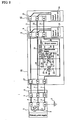
- FIG. 1 is a power supply wiring diagram including a faulty wiring detection device for an air conditioner in accordance with a first embodiment of the present invention.
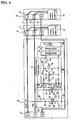
- FIG. 2 is a power supply wiring diagram including the faulty wiring detection device for an air conditioner, where electric signal detection means is described in detail.
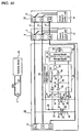
- FIG. 3 is a power supply wiring diagram including the faulty wiring detection device for an air conditioner, where signal detection means and determination means are described in detail.
- FIG. 4 shows wiring patterns of the power lines.
- FIG. 5 shows the waveforms of detection signals provided by the electric signal detection means.
- denoted 1 is a primary power supply that provides a single-phase alternating current, 2 a ground resistance existing between an N-phase of the primary power supply and a ground, 3 a ground point, 4 wiring from the primary power supply, 5 a wall socket for the air conditioner, 6 a power plug of the air conditioner, 7 a power cord of the air conditioner, 8 an indoor unit of the air conditioner, 9 a power supply terminal block of the indoor unit 8, 10 a control board of the indoor unit 8, 11 power supply wiring from the indoor unit 8 to an outdoor unit 12 of the air conditioner, 12 the outdoor unit of the air conditioner, 13 a power supply terminal block of the outdoor unit 12, 14 a control board of the outdoor unit 12, and 16 a faulty wiring detection device for an air conditioner.
- Denoted 17 is a terminal block of the faulty wiring detection device 16 connected to the power plug 6 of the air conditioner, 18 electric signal detection means for reading out a signal for detecting faulty wiring of a power line, 19 determination means that receives the signal from the electric signal detection means and determines the presence/absence of faulty wiring, 20 output means for providing the determination result from the determination means as an output signal for a display or an alarm that works as external displaying/alarming means, and 21 direct-current voltage supply means for providing a direct-current voltage for the electric signal detection means and the determination means.
- the primary power supply 1 in this embodiment is assumed to be, for example, a single-phase two-wire system, 100V of a single-phase three-wire system, or the single-phase power supply of a three-phase four-wire system having a neutral line as N-phase (its power supply voltage is regulated in each country).
- the electric signal detection means 18 is configured as shown in FIG. 2, where denoted 23 is a photo-coupler connected between the L-phase and E on the terminal block 17 of the faulty wiring detection device 16 via a resistor 25 and a capacitor 22, 26 a diode connected in parallel to the photodiode 24 of the photo-coupler 23, and 27 a photo-transistor of which collector is connected to the direct-current voltage supply means 21 via a resistor 28 and emitter of which is connected to an output terminal 39.
- denoted 23 is a photo-coupler connected between the L-phase and E on the terminal block 17 of the faulty wiring detection device 16 via a resistor 25 and a capacitor 22, 26 a diode connected in parallel to the photodiode 24 of the photo-coupler 23, and 27 a photo-transistor of which collector is connected to the direct-current voltage supply means 21 via a resistor 28 and emitter of which is connected to an output terminal 39.
- Denoted 30 is a photo-coupler connected between the N-phase and E on the terminal block 17 via a resistor 32 and a capacitor 29, 33 a diode connected in parallel to the photodiode 31 of the photo-coupler 30, and 34 a photo transistor of which collector is connected to the direct-current voltage supply means 21 via a resistor 35 and emitter of which is connected to an output terminal 38.
- Denoted 36 is a terminal connected to a junction between the resistor 28 and the collector of the photo-transistor 27, while 37 is a terminal connected to a junction between the resistor 35 and the collector of the photo-transistor 34.
- the determination means 19 has such a configuration shown in FIG. 3, where denoted 40 is a NOT circuit (inverter) that inverts a signal sent from the electric signal detection means, likewise 41 a NOT circuit that inverts the signal sent from the electric signal detection means, and 42, 43,and 44 are components constituting an integrator circuit that integrates the output from the NOT circuit 40, where 42 is a resistor, 43 a capacitor, and 44 a resistor.
- 45, 46, and 47 constitute an integrator circuit that integrates the output sent from the NOT circuit 41, where 45 is a resistor, 46 a capacitor,and 47 a resistor.
- Denoted 48 and 49 are logic circuits, where 48 is a NOT circuit and 49 an AND circuit.
- the electric signal detection means 18 of the faulty wiring detection device 16 connected to the power plug 6 of the air conditioner detects the voltage or current between the L-phase and E of the power line as well as between the N-phase and E, and then provides signals according to the presence/absence of such voltage or current.
- the determination means 19 compares a pair of electric signals sent from the electric signal detection means with predetermined signal pairs for normal and faulty wirings, and then determines whether the current wiring is normal or faulty. Since it is powered by the direct-current voltage supply means 21 during determination, it can determine the state of wiring even if the power line is improperly connected.
- the determination result obtained by the determination means 19 is sent to the output means 20.
- the output means 20 drives a display unit (for example, LED or lamp) or an acoustic unit (for example, buzzer or speaker) to notify persons at the site, such as an installation engineer of an air conditioner, of the presence/absence of faulty wiring, and eventually prevents problems posed by faulty wiring.
- a display unit for example, LED or lamp
- an acoustic unit for example, buzzer or speaker
- FIG. 4 there are five patterns of faulty wiring for the power lines 4 connected to the primary power supply 1.
- FIG. 4(a) shows normal wiring
- FIGS. 4(b)-4(f) show faulty wiring patterns.
- the waveforms of the detection signals in the electric signal detection means 18 shown in FIG. 5 correspond to the wiring patterns shown in FIG. 4, respectively.
- FIGS. 5(a)-5(f) show the waveform diagrams of the detection signals corresponding to FIGS. 4(a)-4(f), respectively.
- the photo-coupler 23 of an appropriate amplification factor is chosen, with its ON/OFF characteristics being taken into account. If a current large enough for ON/OFF operations of the photo-coupler 23 runs in the photodiode 24, meeting the requirement shown by the expression (1), then the photo-transistor 27 turns ON/OFF.
- the capacitor 22 is connected to electrically insulate the L-phase of the power line from E.
- the diode 26 is coupled in parallel with the photo-coupler 23 to protect the photo-coupler from a reverse voltage that exceeds its reverse withstand voltage.
- the output of the photo-transistor 27 is provided from the direct-current voltage supply means 21 via the resistor 28, its output voltage falls to near zero when the photo-coupler 23 is turned on, while it becomes equal to the direct-current voltage provided by the direct-current voltage supply means 21 when the photo-coupler 23 is turned off. This output voltage is entered to the determination means 19 via the terminals 36 and 39.
- the resistance (referred to as "R") of the resistor 32 and the capacitance (referred to as “C") of the capacitor 29 of the series circuit made of the resistor 32, photodiode 31 of the photo-coupler 30 and the capacitor 29 connected between the N-phase and E on the terminal block 17 of the electric signal detection means 18 of the faulty wiring detection device 16 are determined to meet the condition shown by the expression (1). Then the current that effects ON/OFF of the photo-coupler 30 runs in the photodiode 31 and the photo-transistor 34 turns ON/OFF. Since the currents running in the photodiodes 24, 31 on the primary side of the photo-couplers 23, 30 are alternating currents, the output changes with time.
- the photo-couplers 23, 30 repetitive are turned ON only during the half cycle of the waveform of the primary power supply and turned off during the other half cycle thereof. In this way, the output voltages of the photo-couplers 23, 30 show ON/OFF pulse waveforms.
- the output of the photo-transistor 34 is provided as a voltage supplied by the direct-current voltage supply means 21 via the resistor 35, its voltage falls to near zero when the photo-coupler 30 is turned on, while it becomes equal to the direct-current voltage provided by.the direct-current voltage supply means 21 when the photo-coupler 30 is turned off. This output voltage is entered to the determination means 19 via the terminals 37, 38.
- the combinations of the output voltages of the photo-couplers 23, 30 are expressed by means of sets, there are four combinations, ⁇ (ON, ON), (ON, OFF), (OFF, ON), (OFF, OFF) ⁇ .
- the combinations of the output voltages are shown in FIG. 5.
- the normal wiring of FIG. 5(a) and the faulty wiring of FIG. 5(b) show the same output pattern, while the other faulty wirings show different output patterns from that of the normal wiring. Thus such faulty wirings can be distinguished from the normal wiring even by a simple logic circuit.
- FIGS. 5(a)-5(f) show the waveforms of L-E voltage of the primary power supply 1, L-E voltage of the wall socket 5 for the air conditioner, voltage between the terminals 36 and 39, N-E voltage of the primary power supply 1, and voltage between the terminals 37 and 38.
- the output changes with time. Namely, the photo-couplers 23, 30 are turned ON only during the half cycle of the waveform of the primary power supply and turned off during the other half cycle thereof. In this way, the output voltages of the photo-couplers 23, 30 show repetitive ON/OFF pulse waveforms.
- the electric signal detection means 18 provides the determination means 19 with signals with such waveforms of the terminal 36-39 voltage and terminal 37-38 voltage as shown in FIGS. 5A-5F, the NOT circuits 40, 41 invert the terminal 36-39 voltage and terminal 37-38 voltage and output them.
- This output signals represent ON/OFF states of the photo-transistors 27, 34 of the photo-couplers 23, 30.
- this output signal has a pulse waveform
- a set of stable output signals that do not change with time is provided by converting the pulse waveform into a square waveform.
- the NOT circuit 40 is coupled with the integrator circuit composed of the resistors 42, 44 and capacitor 43. This integrator circuit converts pulse waveforms into square waveforms.
- the NOT circuit 41 is coupled with the integrator circuit composed of the resistors 45, 47 and capacitor 46, and this integrator circuit converts pulse waveforms into square waveforms.
- the ON/OFF pulse waveforms of the photo-couplers 23, 30 become stable at the voltage Vcc that is provided by the direct-current voltage supply means 21. Meanwhile, zero volts are provided when the photo-couplers 23, 30 are turned off.
- the voltage waveform between the terminals 36 and 39 shows Vcc when it passes the NOT circuit 40 and the integrator circuit for the case of normal wiring.
- the voltage waveform between the terminals 37 and 38 shows zero when it passes the NOT circuit 41 and the integrator circuit.
- the faulty wiring pattern 1 shown in (b) where the power line and the ground line are exchanged can be regarded as equal to the normal wiring shown in (a).
- the determination results become as follows.
- the involved logic circuits are the NOT circuit 48 and the AND circuit 49 shown in FIG. 3.
- a determination result "H” is sent to the output means 20 in the case of normal wiring, while “L” is sent in the case of faulty wiring. If the reverse results are necessary in the output, a NAND circuit instead of the AND circuit 49 is used.
- a circuit of wide use can be configured by changing the output means 20, such as an alarm, alarm lamp,or relay connected to another apparatus, depending on an external apparatus for outputting when a determination result is sent to the output means 20.
- the resistors 25, 32 may be eliminated and the same result is provided.
- the status of wiring can be determined whether normal or faulty, using the table that describes the combinations of wiring pattern and output result.
- Table 1 can be used for the power supply systems including the single-phase two-wire 100V and 200V systems, single-phase three-wire 100V system, and single-phase two-wire system using the neutral line of a three-phase four-wire system as the N-phase. Meanwhile, for the single-phase three-wire 200V system, Table 1 takes the form of different truth table, Table 2. Thus each determination result is provided by the following expression.
- the logic circuits of the determination means are modified to perform the same determination as that described above. It thereby becomes possible to detect faulty wiring.
- the electric signal detection means 18 comprises the resistors 25, 32, capacitors 22, 29 and photo-couplers 23, 30. However, it may be formed by either combination of resistors and photo-couplers or of capacitors and photo-couplers for simplified structure.
- FIG. 6 is a power supply wiring diagram including a faulty wiring detection device for an air conditioner in accordance with a second embodiment of the present invention.
- the electric signal detection means using photo-couplers has been described.
- electric signal detection means uses resistors and capacitors.
- the same numerals are given to the same components as or similar components to those in FIG. 3 of the first embodiment, and their explanation is not repeated.
- the electric signal detection means 18 denoted 59 is a voltage detection circuit that detects a voltage across the resistor 25 connected between the L-phase and E, while 60 is a voltage detection circuit that detects a voltage across the resistor 32 connected between the N-phase and E.
- the other part of the electric signal detection means 18 is the same as that of the first embodiment.
- the voltage detection circuits 59 and 60 provide ON/OFF signals for the determination means 19 when a voltage is applied between the L-phase and E and between the N-phase and E, respectively.
- the voltage detection circuits 59, 60 detect voltages by connecting both ends of each of the resistors 25, 32 to a transistor and setting ON/OFF output conditions.
- the output voltages provided from the voltage detection circuits 59, 60 are sent to the determination means 19. Then, likewise the operation described in the first embodiment, the wiring is determined whether normal or faulty and problems such as overheat in the circuit can be prevented.
- FIG. 7 is a power supply wiring diagram including a faulty wiring detection device for an air conditioner in accordance with a third embodiment of the present invention.
- the electric signal detection means employs resistors 25, 32, these resistances serve as the insulation resistance.
- resistors 25, 32 serve as the insulation resistance.
- resistors of a considerably large resistance must be employed in the circuit. Because such resistors may cause noise problems, this embodiment employs capacitors 22, 29 instead of the resistors 25, 32.
- capacitors are connected, it becomes possible to use resistors of a lower resistance or even eliminate resistors for ensuring a required insulation. At the same time, it is possible to meet safety requirements by determining an appropriate capacitance for each of the capacitors through calculation.
- the power supply voltage may be either 100V or 200V in the single-phase three-wire system as well as the single-phase two-wire system.
- the capacitances of the capacitors 22, 29 constituting the electric signal detection means 18 may be changed; or a resistor is serially connected to each of the capacitors 22, 29 and the resistance of each resistor may be changed with no change to the capacitances of the capacitors 22, 29.
- a plurality of the same capacitors are connected, it has the same effect as changing the size of capacitance of a capacitor.
- FIG. 8 is a power supply wiring diagram including a faulty wiring detection device for an air conditioner in accordance with a fourth embodiment of the present invention.
- the electric signal detection means 18 yields a leak current in the ground line, the operation of the air conditioner may be affected. To eliminate such risk, this embodiment provides an improvement for detecting faulty wiring without affecting the operation of the air conditioner.
- the output means 20 may be a display (such as LED and lump), an acoustic device (such as a buzzer), or provision of signals for a relay to external devices.
- the output means 20 is composed of a self-holding circuit 50 (such as a flip-flop circuit) that temporarily retains the output from the determination means 19 and a driving circuit S1 that drives a relay 52.
- Denoted 53 is shut-off means that is inserted between the L-phase and E of the power line of the electric signal detection means and comprises a relay 52X
- 54 is shut-off means that is inserted between the N-phase and E of the power line of the electric signal detection means and comprises a relay 52X.
- the relay 52X uses a b-contact.
- FIG. 9 is a power supply wiring diagram including a faulty wiring detection device for an air conditioner in accordance with a fifth embodiment of the present invention.
- the L-phase and N-phase of the electric signal detection means are shut off from E. In this embodiment, however, the power line itself is shut off.
- the same numerals are given to the same components as or similar components to those in FIG. 8 of the fourth embodiment, and their explanation is not repeated.
- Denoted 55 is shut-off means that is provided for the L-phase of the power line and comprises a relay 52X, while 56 is shut-off means that is provided for the N-phase of the power line and comprises a relay 52X.
- the relay 52X us es a b-contact.
- the relay 52X is driven by the relay driving circuit 51, with the output from the determination means 19 being retained temporarily in the self-holding circuit 50 of the output means 20, and the shut-off means 55, 56 shut off the respective connections of the L- and N-phase of the power line to disconnect the power line from the air conditioner. Since the wiring on the air conditioner side is disconnected, it is possible to prevent problems arising from faulty wiring. Besides, since no power is provided for the air conditioner, the air conditioner is not activated and the safety in case of faulty wiring is further improved.
- FIG. 10 is a power supply wiring diagram including a faulty wiring detection device for an air conditioner in accordance with a sixth embodiment of the present invention.
- the output means controls an external device.
- Denoted 58 is an external device and 57 shut-off means comprising a relay 52X installed between the primary power supply 1 and the external device 58.
- the external device 58 deactivates the shut-off means 57 in the case of normal wiring while activating it in the case of faulty wiring.
- the contact of the relay 52X may be chosen from a-contact and b-contact.
- the faulty wiring detection device for detecting faulty wiring of an air conditioner which is powered by a single-phase two-wire system, a single-phase three-wire system, or a single-phase lower voltage of a three-phase four-wire system, comprises: electric signal detection means for detecting an electric signal in between a ground line, a neutral line of the power supply system or one power line (referred to as "N-phase") of a single-phase three-wire system and a ground line (simply referred to as "E"), and between a power line or the other power line (referred to as "L-phase”) with respect to the N-phase power line of the single-phase three-wire system and E; determination means for determining presence/absence of faulty wiring in power lines connected to the aforementioned power supply terminal block based on the electric signal provided by the electric signal detection means; and output means for driving a display or alarm means that shows a determination result provided by the determination means.
- the electric signal detection means comprises photo-couplers connected between the L-phase and E and between the N-phase and E respectively, the alternating-current power supply side is insulated from the direct-current circuit side. This makes it possible to detect faulty wiring in its primary power line during installation of an air conditioner with the device of a simple structure, and to notify the presence/absence of faulty wiring with a display, alarm or other means.
- the electric signal detection means comprises resistors connected between the L-phase and E and between the N-phase and E, respectively. This makes it possible to detect faulty wiring in its primary power line during installation of an air conditioner with the device of a simple structure, and to notify the presence/absence of faulty wiring with a display, alarm or other means.
- the electric signal detection means comprises capacitors connected between the L-phase and E and between the N-phase and E respectively, this makes it possible to provide an electric insulation, lower the resistance and leak current, and eventually easily meet safety standards.
- shut-off means for shutting off the electric signal detection means from the N-phase and L-phase based on a signal provided by the output means when the determination means has detected faulty wiring, it becomes possible to use the devise without affecting the operation of the air conditioner.
- shut-off means for shutting off the power lines from the air conditioner based on a signal provided by the output means when the determination means has detected faulty wiring, it becomes possible to prevent problems such as overheating in the wiring caused by faulty wiring.
- shut-off means for shutting off the power lines from an external device of the air conditioner based on a signal provided by the output means when the determination means has detected faulty wiring, it becomes possible to change the output means in accordance with the type of employed determination means and thereby provide a device of higher flexibility.
Applications Claiming Priority (2)
| Application Number | Priority Date | Filing Date | Title |
|---|---|---|---|
| JP2002064166 | 2002-03-08 | ||
| JP2002064166A JP4110510B2 (ja) | 2002-03-08 | 2002-03-08 | 空気調和機の誤配線検出装置 |
Publications (3)
| Publication Number | Publication Date |
|---|---|
| EP1343016A2 EP1343016A2 (en) | 2003-09-10 |
| EP1343016A3 EP1343016A3 (en) | 2004-01-14 |
| EP1343016B1 true EP1343016B1 (en) | 2006-04-05 |
Family
ID=27606578
Family Applications (1)
| Application Number | Title | Priority Date | Filing Date |
|---|---|---|---|
| EP02254633A Expired - Fee Related EP1343016B1 (en) | 2002-03-08 | 2002-07-02 | Faulty wiring detection device for air conditioner |
Country Status (6)
| Country | Link |
|---|---|
| US (1) | US6777954B2 (ja) |
| EP (1) | EP1343016B1 (ja) |
| JP (1) | JP4110510B2 (ja) |
| CN (1) | CN1266480C (ja) |
| AU (1) | AU763395B1 (ja) |
| ES (1) | ES2257509T3 (ja) |
Families Citing this family (27)
| Publication number | Priority date | Publication date | Assignee | Title |
|---|---|---|---|---|
| JP2007526992A (ja) * | 2003-07-09 | 2007-09-20 | イスラーユック エレクトロニクス リミテッド | 電気故障検出のためのシステム、装置、及び方法 |
| JP4276157B2 (ja) * | 2003-10-09 | 2009-06-10 | 三星エスディアイ株式会社 | プラズマディスプレイパネル及びその駆動方法 |
| US7355412B1 (en) * | 2004-08-05 | 2008-04-08 | Cannon Technologies, Inc. | Remote fault monitoring system |
| US7400150B2 (en) * | 2004-08-05 | 2008-07-15 | Cannon Technologies, Inc. | Remote fault monitoring in power lines |
| JP3806882B2 (ja) * | 2004-11-29 | 2006-08-09 | ダイキン工業株式会社 | 空気調和機 |
| WO2006078869A2 (en) * | 2005-01-19 | 2006-07-27 | Cannon Technologies, Inc. | Remote fault monitoring in power lines |
| CN1987396B (zh) * | 2005-12-22 | 2010-07-07 | 乐金电子(天津)电器有限公司 | 复合式空调器错误连线及配管温度传感器不良的检测方法 |
| JP2009079811A (ja) * | 2007-09-26 | 2009-04-16 | Sanyo Electric Co Ltd | 空気調和システムおよび室内機 |
| JP4874202B2 (ja) * | 2007-09-26 | 2012-02-15 | 三洋電機株式会社 | 空気調和システムおよび室外機 |
| WO2009082395A1 (en) * | 2007-12-21 | 2009-07-02 | Carrier Corporation | Method and system for low-power three-phase detection |
| JP5319949B2 (ja) * | 2008-03-31 | 2013-10-16 | パナソニック株式会社 | 配線器具 |
| JP5436881B2 (ja) * | 2009-02-13 | 2014-03-05 | 三洋電機株式会社 | 空気調和装置 |
| KR101610851B1 (ko) * | 2010-05-31 | 2016-04-12 | 삼성전자 주식회사 | 실내기 및 이를 가지는 공기조화시스템 |
| CN101871981B (zh) * | 2010-06-01 | 2012-05-09 | 佛山市中格威电子有限公司 | 一种用于空调的自动检测、调整方法及电路 |
| JP5162723B1 (ja) * | 2012-02-20 | 2013-03-13 | ランズバーグ・インダストリー株式会社 | 静電塗装ケーブル保全装置 |
| MY166408A (en) * | 2012-04-25 | 2018-06-25 | Panasonic Appliances Air Conditioning R&D Malaysia Sdn Bhd | Air conditioner |
| CN104034998B (zh) * | 2014-06-20 | 2017-01-18 | 珠海格力电器股份有限公司 | 一种定频空调内外机连接线接错的诊断方法及诊断系统 |
| CN104101064A (zh) * | 2014-06-21 | 2014-10-15 | 广东格兰仕集团有限公司 | 变频空调的室内外机电源接线错误保护装置 |
| AU2016363110B2 (en) * | 2015-12-01 | 2017-08-17 | Neil Lindsay | A safety device for a power supply or appliance coupled thereto |
| US10139454B2 (en) * | 2016-01-20 | 2018-11-27 | Test Research, Inc. | Test device and alternating current power detection method of the same |
| CN107219434A (zh) * | 2017-07-11 | 2017-09-29 | 珠海格力电器股份有限公司 | 空调故障检测连接线及空调故障检测方法 |
| KR102642560B1 (ko) * | 2018-09-21 | 2024-02-28 | 엘지전자 주식회사 | 단상 3선식 배선 구조가 적용된 전자 장치 |
| CN109682040B (zh) * | 2018-12-04 | 2021-07-20 | 格力电器(武汉)有限公司 | 一种空调线序检测装置和方法 |
| CN109751710A (zh) * | 2019-01-11 | 2019-05-14 | 青岛海尔空调电子有限公司 | 压缩机控制装置、系统、室外机、空调及压缩机控制方法 |
| KR20220010863A (ko) * | 2020-07-20 | 2022-01-27 | 삼성전자주식회사 | 전자 장치 및 그 제어 방법 |
| CN112798983B (zh) * | 2020-12-30 | 2022-03-01 | 珠海格力电器股份有限公司 | 一种检测内外机连接线的方法及装置 |
| CN113659817B (zh) * | 2021-07-26 | 2023-02-28 | 广东志成冠军集团有限公司 | 三相四桥臂并网逆变器容错控制方法及系统 |
Family Cites Families (18)
| Publication number | Priority date | Publication date | Assignee | Title |
|---|---|---|---|---|
| DE160016C (ja) | ||||
| US3810003A (en) * | 1971-07-06 | 1974-05-07 | Ecos Corp | Device for determining improper reversal and/or short of ground and neutral lines and amount of impedance in ground line of a three-wire a.c. outlet |
| US4016489A (en) | 1974-10-04 | 1977-04-05 | Hill-Rom Company, Inc. | Ground-test circuit with minimal ground current |
| AU3433778A (en) | 1977-04-01 | 1979-09-27 | Freckleton D N R | Testing supply outlet connections |
| US4164701A (en) | 1977-09-06 | 1979-08-14 | Austin Lloyd M | Portable device for testing electrical wiring circuits and power tools and equipment |
| DD160016A1 (de) * | 1981-06-29 | 1983-04-20 | Volker Deckert | Anordnung zur fehlerermittlung in kabeln und verdrahtungen |
| JPS63190389A (ja) | 1987-02-03 | 1988-08-05 | Iwatsu Electric Co Ltd | 電源信号発生回路 |
| JPS6423051A (en) | 1987-07-15 | 1989-01-25 | Matsushita Seiko Kk | Information transmission circuit for air conditioner |
| JPH02241367A (ja) | 1989-03-15 | 1990-09-26 | Mitsubishi Electric Corp | 直流電源装置 |
| JPH03244983A (ja) * | 1990-02-23 | 1991-10-31 | Toshiba Corp | 空気調和機 |
| US5250908A (en) * | 1991-12-13 | 1993-10-05 | Magl Power & Electronics, Inc. | Portable apparatus for testing multi-wire harnesses and electrical assemblies to identify wiring errors |
| US5525908A (en) * | 1993-11-01 | 1996-06-11 | Seg Corporation | Electrical outlet wiring analyzer with full cycle pulsing |
| JP2711518B2 (ja) | 1994-12-28 | 1998-02-10 | 株式会社関電工 | コンセント配線チェッカー及び配線検知方法 |
| US5625285A (en) | 1995-06-01 | 1997-04-29 | A. W. Sperry Instruments, Inc. | AC power outlet ground integrity and wire test circuit device |
| US5642052A (en) * | 1995-06-05 | 1997-06-24 | Etcon Corporation | Hand-held tester for receptacle ground fault circuit interrupters |
| JP3193296B2 (ja) | 1996-06-20 | 2001-07-30 | 矢崎総業株式会社 | 屋内配線結線装置の導通検査方法及び導通検査装置 |
| JPH10332761A (ja) * | 1997-05-29 | 1998-12-18 | Toshiba Corp | 結線状態判定方法及びこの方法を実施する手段を備えた空気調和装置 |
| JP4107789B2 (ja) * | 2000-08-10 | 2008-06-25 | 三洋電機株式会社 | 電源逆相検知回路 |
-
2002
- 2002-03-08 JP JP2002064166A patent/JP4110510B2/ja not_active Expired - Fee Related
- 2002-06-26 US US10/179,987 patent/US6777954B2/en not_active Expired - Fee Related
- 2002-06-26 AU AU50632/02A patent/AU763395B1/en not_active Ceased
- 2002-07-02 ES ES02254633T patent/ES2257509T3/es not_active Expired - Lifetime
- 2002-07-02 EP EP02254633A patent/EP1343016B1/en not_active Expired - Fee Related
- 2002-09-06 CN CNB021318301A patent/CN1266480C/zh not_active Expired - Fee Related
Also Published As
| Publication number | Publication date |
|---|---|
| EP1343016A3 (en) | 2004-01-14 |
| CN1444047A (zh) | 2003-09-24 |
| ES2257509T3 (es) | 2006-08-01 |
| CN1266480C (zh) | 2006-07-26 |
| JP4110510B2 (ja) | 2008-07-02 |
| EP1343016A2 (en) | 2003-09-10 |
| AU763395B1 (en) | 2003-07-24 |
| US20030169052A1 (en) | 2003-09-11 |
| JP2003262381A (ja) | 2003-09-19 |
| US6777954B2 (en) | 2004-08-17 |
Similar Documents
| Publication | Publication Date | Title |
|---|---|---|
| EP1343016B1 (en) | Faulty wiring detection device for air conditioner | |
| US5737168A (en) | Electrical power management system | |
| US5065104A (en) | Fault sensing with an artificial reference potential provided by an isolated capacitance effect | |
| GB2342455A (en) | Anti-static earth connection test system | |
| US4421976A (en) | System for monitoring heater elements of electric furnaces | |
| US6031700A (en) | Ground detector for a static grounding system | |
| US7003412B2 (en) | Method and system for verifying voltage in an electrical system | |
| JPH07255124A (ja) | 相順配線保護装置 | |
| US3708721A (en) | Electrical connection and ground monitor | |
| US2442771A (en) | Testing device for electric tools and appliances | |
| JP2001208778A (ja) | 検出電流合成装置、および分電盤 | |
| JPH01144322A (ja) | 電気機器 | |
| KR200203518Y1 (ko) | 다기능 매립형 콘센트 | |
| US4233598A (en) | Emergency stop circuit monitoring system | |
| KR100455033B1 (ko) | 접지상태 표시장치 | |
| KR100376101B1 (ko) | 누전차단기 시험장치 | |
| KR200284070Y1 (ko) | 접지상태 표시장치 | |
| EP3806260A1 (en) | Phase line and neutral detection circuit | |
| JP7357725B2 (ja) | 配線状態検知装置 | |
| JPH04174371A (ja) | 接地極付電源コンセントの配線状態検査治具 | |
| JP6741314B2 (ja) | 差込接続ユニット | |
| KR200342993Y1 (ko) | 차단기 동작코일의 단선유무 감지회로 | |
| KR200225521Y1 (ko) | 누전차단기 시험장치 | |
| KR0133418Y1 (ko) | 접지전위를 이용한 전자파 차단 누전차단기 | |
| KR100431903B1 (ko) | 전자식 43pd 스위치 |
Legal Events
| Date | Code | Title | Description |
|---|---|---|---|
| PUAI | Public reference made under article 153(3) epc to a published international application that has entered the european phase |
Free format text: ORIGINAL CODE: 0009012 |
|
| AK | Designated contracting states |
Kind code of ref document: A2 Designated state(s): AT BE BG CH CY CZ DE DK EE ES FI FR GB GR IE IT LI LU MC NL PT SE SK TR |
|
| AX | Request for extension of the european patent |
Extension state: AL LT LV MK RO SI |
|
| PUAL | Search report despatched |
Free format text: ORIGINAL CODE: 0009013 |
|
| RIC1 | Information provided on ipc code assigned before grant |
Ipc: 7G 01R 31/02 A Ipc: 7F 24F 11/02 B |
|
| AK | Designated contracting states |
Kind code of ref document: A3 Designated state(s): AT BE BG CH CY CZ DE DK EE ES FI FR GB GR IE IT LI LU MC NL PT SE SK TR |
|
| AX | Request for extension of the european patent |
Extension state: AL LT LV MK RO SI |
|
| 17P | Request for examination filed |
Effective date: 20040127 |
|
| AKX | Designation fees paid |
Designated state(s): ES IT |
|
| REG | Reference to a national code |
Ref country code: DE Ref legal event code: 8566 |
|
| GRAP | Despatch of communication of intention to grant a patent |
Free format text: ORIGINAL CODE: EPIDOSNIGR1 |
|
| GRAS | Grant fee paid |
Free format text: ORIGINAL CODE: EPIDOSNIGR3 |
|
| GRAA | (expected) grant |
Free format text: ORIGINAL CODE: 0009210 |
|
| AK | Designated contracting states |
Kind code of ref document: B1 Designated state(s): ES IT |
|
| RAP2 | Party data changed (patent owner data changed or rights of a patent transferred) |
Owner name: MITSUBISHI DENKI KABUSHIKI KAISHA |
|
| REG | Reference to a national code |
Ref country code: ES Ref legal event code: FG2A Ref document number: 2257509 Country of ref document: ES Kind code of ref document: T3 |
|
| PLBE | No opposition filed within time limit |
Free format text: ORIGINAL CODE: 0009261 |
|
| STAA | Information on the status of an ep patent application or granted ep patent |
Free format text: STATUS: NO OPPOSITION FILED WITHIN TIME LIMIT |
|
| 26N | No opposition filed |
Effective date: 20070108 |
|
| REG | Reference to a national code |
Ref country code: ES Ref legal event code: GC2A Effective date: 20120215 |
|
| PGFP | Annual fee paid to national office [announced via postgrant information from national office to epo] |
Ref country code: ES Payment date: 20140611 Year of fee payment: 13 |
|
| PGFP | Annual fee paid to national office [announced via postgrant information from national office to epo] |
Ref country code: IT Payment date: 20140708 Year of fee payment: 13 |
|
| PG25 | Lapsed in a contracting state [announced via postgrant information from national office to epo] |
Ref country code: IT Free format text: LAPSE BECAUSE OF NON-PAYMENT OF DUE FEES Effective date: 20150702 |
|
| REG | Reference to a national code |
Ref country code: ES Ref legal event code: FD2A Effective date: 20170127 |
|
| PG25 | Lapsed in a contracting state [announced via postgrant information from national office to epo] |
Ref country code: ES Free format text: LAPSE BECAUSE OF NON-PAYMENT OF DUE FEES Effective date: 20150703 |