EP1340830A1 - Bimetall-Sägeband - Google Patents
Bimetall-Sägeband Download PDFInfo
- Publication number
- EP1340830A1 EP1340830A1 EP03002794A EP03002794A EP1340830A1 EP 1340830 A1 EP1340830 A1 EP 1340830A1 EP 03002794 A EP03002794 A EP 03002794A EP 03002794 A EP03002794 A EP 03002794A EP 1340830 A1 EP1340830 A1 EP 1340830A1
- Authority
- EP
- European Patent Office
- Prior art keywords
- saw band
- molybdenum
- steel
- tungsten
- vanadium
- Prior art date
- Legal status (The legal status is an assumption and is not a legal conclusion. Google has not performed a legal analysis and makes no representation as to the accuracy of the status listed.)
- Granted
Links
Images


Classifications
-
- C—CHEMISTRY; METALLURGY
- C22—METALLURGY; FERROUS OR NON-FERROUS ALLOYS; TREATMENT OF ALLOYS OR NON-FERROUS METALS
- C22C—ALLOYS
- C22C38/00—Ferrous alloys, e.g. steel alloys
- C22C38/18—Ferrous alloys, e.g. steel alloys containing chromium
- C22C38/40—Ferrous alloys, e.g. steel alloys containing chromium with nickel
- C22C38/42—Ferrous alloys, e.g. steel alloys containing chromium with nickel with copper
-
- B—PERFORMING OPERATIONS; TRANSPORTING
- B23—MACHINE TOOLS; METAL-WORKING NOT OTHERWISE PROVIDED FOR
- B23D—PLANING; SLOTTING; SHEARING; BROACHING; SAWING; FILING; SCRAPING; LIKE OPERATIONS FOR WORKING METAL BY REMOVING MATERIAL, NOT OTHERWISE PROVIDED FOR
- B23D61/00—Tools for sawing machines or sawing devices; Clamping devices for these tools
- B23D61/12—Straight saw blades; Strap saw blades
- B23D61/127—Straight saw blades; Strap saw blades of special material
-
- C—CHEMISTRY; METALLURGY
- C22—METALLURGY; FERROUS OR NON-FERROUS ALLOYS; TREATMENT OF ALLOYS OR NON-FERROUS METALS
- C22C—ALLOYS
- C22C38/00—Ferrous alloys, e.g. steel alloys
- C22C38/04—Ferrous alloys, e.g. steel alloys containing manganese
-
- C—CHEMISTRY; METALLURGY
- C22—METALLURGY; FERROUS OR NON-FERROUS ALLOYS; TREATMENT OF ALLOYS OR NON-FERROUS METALS
- C22C—ALLOYS
- C22C38/00—Ferrous alloys, e.g. steel alloys
- C22C38/18—Ferrous alloys, e.g. steel alloys containing chromium
- C22C38/22—Ferrous alloys, e.g. steel alloys containing chromium with molybdenum or tungsten
-
- C—CHEMISTRY; METALLURGY
- C22—METALLURGY; FERROUS OR NON-FERROUS ALLOYS; TREATMENT OF ALLOYS OR NON-FERROUS METALS
- C22C—ALLOYS
- C22C38/00—Ferrous alloys, e.g. steel alloys
- C22C38/18—Ferrous alloys, e.g. steel alloys containing chromium
- C22C38/24—Ferrous alloys, e.g. steel alloys containing chromium with vanadium
-
- C—CHEMISTRY; METALLURGY
- C22—METALLURGY; FERROUS OR NON-FERROUS ALLOYS; TREATMENT OF ALLOYS OR NON-FERROUS METALS
- C22C—ALLOYS
- C22C38/00—Ferrous alloys, e.g. steel alloys
- C22C38/18—Ferrous alloys, e.g. steel alloys containing chromium
- C22C38/30—Ferrous alloys, e.g. steel alloys containing chromium with cobalt
-
- C—CHEMISTRY; METALLURGY
- C22—METALLURGY; FERROUS OR NON-FERROUS ALLOYS; TREATMENT OF ALLOYS OR NON-FERROUS METALS
- C22C—ALLOYS
- C22C38/00—Ferrous alloys, e.g. steel alloys
- C22C38/18—Ferrous alloys, e.g. steel alloys containing chromium
- C22C38/36—Ferrous alloys, e.g. steel alloys containing chromium with more than 1.7% by weight of carbon
-
- C—CHEMISTRY; METALLURGY
- C22—METALLURGY; FERROUS OR NON-FERROUS ALLOYS; TREATMENT OF ALLOYS OR NON-FERROUS METALS
- C22C—ALLOYS
- C22C38/00—Ferrous alloys, e.g. steel alloys
- C22C38/18—Ferrous alloys, e.g. steel alloys containing chromium
- C22C38/40—Ferrous alloys, e.g. steel alloys containing chromium with nickel
- C22C38/44—Ferrous alloys, e.g. steel alloys containing chromium with nickel with molybdenum or tungsten
-
- C—CHEMISTRY; METALLURGY
- C22—METALLURGY; FERROUS OR NON-FERROUS ALLOYS; TREATMENT OF ALLOYS OR NON-FERROUS METALS
- C22C—ALLOYS
- C22C38/00—Ferrous alloys, e.g. steel alloys
- C22C38/18—Ferrous alloys, e.g. steel alloys containing chromium
- C22C38/40—Ferrous alloys, e.g. steel alloys containing chromium with nickel
- C22C38/46—Ferrous alloys, e.g. steel alloys containing chromium with nickel with vanadium
-
- C—CHEMISTRY; METALLURGY
- C22—METALLURGY; FERROUS OR NON-FERROUS ALLOYS; TREATMENT OF ALLOYS OR NON-FERROUS METALS
- C22C—ALLOYS
- C22C38/00—Ferrous alloys, e.g. steel alloys
- C22C38/18—Ferrous alloys, e.g. steel alloys containing chromium
- C22C38/40—Ferrous alloys, e.g. steel alloys containing chromium with nickel
- C22C38/48—Ferrous alloys, e.g. steel alloys containing chromium with nickel with niobium or tantalum
-
- Y—GENERAL TAGGING OF NEW TECHNOLOGICAL DEVELOPMENTS; GENERAL TAGGING OF CROSS-SECTIONAL TECHNOLOGIES SPANNING OVER SEVERAL SECTIONS OF THE IPC; TECHNICAL SUBJECTS COVERED BY FORMER USPC CROSS-REFERENCE ART COLLECTIONS [XRACs] AND DIGESTS
- Y10—TECHNICAL SUBJECTS COVERED BY FORMER USPC
- Y10T—TECHNICAL SUBJECTS COVERED BY FORMER US CLASSIFICATION
- Y10T428/00—Stock material or miscellaneous articles
- Y10T428/12—All metal or with adjacent metals
- Y10T428/12493—Composite; i.e., plural, adjacent, spatially distinct metal components [e.g., layers, joint, etc.]
- Y10T428/12771—Transition metal-base component
- Y10T428/12861—Group VIII or IB metal-base component
- Y10T428/12951—Fe-base component
- Y10T428/12958—Next to Fe-base component
- Y10T428/12965—Both containing 0.01-1.7% carbon [i.e., steel]
-
- Y—GENERAL TAGGING OF NEW TECHNOLOGICAL DEVELOPMENTS; GENERAL TAGGING OF CROSS-SECTIONAL TECHNOLOGIES SPANNING OVER SEVERAL SECTIONS OF THE IPC; TECHNICAL SUBJECTS COVERED BY FORMER USPC CROSS-REFERENCE ART COLLECTIONS [XRACs] AND DIGESTS
- Y10—TECHNICAL SUBJECTS COVERED BY FORMER USPC
- Y10T—TECHNICAL SUBJECTS COVERED BY FORMER US CLASSIFICATION
- Y10T428/00—Stock material or miscellaneous articles
- Y10T428/12—All metal or with adjacent metals
- Y10T428/12493—Composite; i.e., plural, adjacent, spatially distinct metal components [e.g., layers, joint, etc.]
- Y10T428/12771—Transition metal-base component
- Y10T428/12861—Group VIII or IB metal-base component
- Y10T428/12951—Fe-base component
- Y10T428/12972—Containing 0.01-1.7% carbon [i.e., steel]
- Y10T428/12979—Containing more than 10% nonferrous elements [e.g., high alloy, stainless]
-
- Y—GENERAL TAGGING OF NEW TECHNOLOGICAL DEVELOPMENTS; GENERAL TAGGING OF CROSS-SECTIONAL TECHNOLOGIES SPANNING OVER SEVERAL SECTIONS OF THE IPC; TECHNICAL SUBJECTS COVERED BY FORMER USPC CROSS-REFERENCE ART COLLECTIONS [XRACs] AND DIGESTS
- Y10—TECHNICAL SUBJECTS COVERED BY FORMER USPC
- Y10T—TECHNICAL SUBJECTS COVERED BY FORMER US CLASSIFICATION
- Y10T83/00—Cutting
- Y10T83/929—Tool or tool with support
- Y10T83/9319—Toothed blade or tooth therefor
Definitions
- the invention relates to a bimetal saw band, in which at least the tooth tips made of wear-resistant steel and the carrier tape a comparatively tough steel.
- Saw bands including jigsaws, need high dimensional stability as well as high wear resistance and high stress due to pressure, bending and shear forces even with the not insignificant ones Temperatures have grown due to the friction between Saw band and material to be cut result. This applies in particular to saw bands, that rotate at high speed and one when deflected by 180 ° subject to strong bending.
- Bimetallic bandsaw blades Because it is difficult to combine the required properties in one Bimetallic bandsaw blades usually exist today to combine material from a relatively tough carrier tape with high flexural fatigue strength and also a band-shaped cutting part from one High-speed steel with lower toughness but high wear resistance.
- the cutting band is so wide that at least the tooth tips result from it of the saw band or blade or the cutting teeth as a whole let work out.
- EP 0 569 346 A1 has already disclosed a bimetallic band or blade from a steel carrier tape with 0.20 to 0.40% carbon, 2.5 to 5.0% Chromium, 2.0 to 3.0% molybdenum, 0.03 to 0.04% vanadium and as a grain refiner a total of less than 0.01% niobium and titanium on the one hand and one High-speed steel cutting tape with 0.65 to 1.8% carbon, 3.0 to 6.0% chromium, 4.0 to 12.0% molybdenum and 0.5 to 5.0% vanadium known.
- a special feature of this saw band is from the point of view sufficient fatigue strength or fatigue strength the simultaneous presence of chromium, vanadium and molybdenum in both materials as well as the limitation of the total content Niobium and titanium in the carrier tape to a maximum of 0.01%.
- Both materials of the saw band also contain aluminum, up to 2.0% in the cutting part and up to 0.15% in the carrier tape.
- Japanese laid-open specification 63-007 351 describes a Bimetal saw band with high toughness and fatigue strength from a low alloy steel with 0.25 to 0.50% carbon, under 1.5% nickel, 2.00 up to 6.00% chromium, 0.20 to 1.00% vanadium, 0.20 to 1.00% molybdenum and / or below 1.50% tungsten, below 0.30% silicon, below 0.50% manganese, below 0.015% phosphorus and below 0.005% sulfur at a total of 0.20 to 1.00% molybdenum and half the tungsten content, under 0.0015% oxygen, 0.02 to 0.20% niobium and / or 0.02 to 0.20% titanium and a cutting part from a high speed steel.
- a carrier steel strip is from US Pat. No. 4,058,650 0.20 to 0.33% carbon, up to 1.5% silicon, up to 1.5% manganese, 3.5 to 6.5% chromium, 0.05 to 0.40% vanadium, 0.05 to 0.10% aluminum, 0.02 to 0.30% niobium, 1.0 to 3.0% molybdenum and / or to 4.0% tungsten and one Total molybdenum content and half the tungsten content from 1.0 to 3.0% known to improve the fatigue strength and toughness of the Basic structure can still contain up to 1.4% cobalt and up to 1.5% nickel.
- This carrier tape material is said to have low decarburization and Mark structural stability when welding with the cutting part and neither lose its toughness when the cutting part is heat treated even when tempering at higher temperatures with regard to fatigue strength ensure a hardness of approximately HRC 50.
- the cutting performance is not only dependent on the band speed (Circulation speed) depends, but also on the Feed speed of the saw band towards the material to be cut, i.e. of the contact pressure.
- the band speed i.e. of the contact pressure.
- heat development limits the possible increase in the cutting speed with regard to the limited heat resistance of the cutting teeth, so that the belt speed cannot be increased arbitrarily.
- the cutting performance can be improved with a higher feed rate or cutting pressure, because then the saw teeth deeper into the penetrate the material to be cut, then the material created during cutting Frictional heat better distributed and in the material to be cut is derived.
- To ensure a smooth or straight saw cut is also a higher one corresponding to the increased feed Blade tension required, which is only possible if the carrier tape material has sufficient flexural fatigue strength.
- An increase in the saw band feed or the contact pressure can be increased with the help of pressure rollers acting on the back of the belt.
- Pressure rollers usually consist of hard metal and lead in the approximately linear contact area with the band back to a special dynamic loading of the carrier tape material, which is supported by an elastic, but also partly linked to plastic deformation of the band back is.
- the deformation follows due to the high belt speed and the linear contact between the pressure roller and the back of the belt always a quick and complete relief.
- the band back is subject hence a strong cyclical load with a high frequency.
- the invention aims to follow from the use of a pressure roller Avoid disadvantages.
- the invention proposes a special carrier tape material in the form of a steel with 0.25 to 0.35% carbon, 0.3 to 0.5% silicon, 0.8 to 1.5% manganese, 1.0 to 2.0% molybdenum, 1.5 to 3.5% Chromium, 0.5 to 1.5% nickel, 0.5 to 2.5% tungsten, 0.15 to 0.30% vanadium, 0.05 to 0.10% niobium, 0.05 to 1.0% copper, up to 0.2% aluminum and bis 1% cobalt, remainder iron including impurities due to melting in front.
- This steel is particularly suitable as a carrier material in connection with cutting teeth made of high-speed steel with 1.0 to 2.0% carbon, 3 to 6% chromium, 1 to 5% vanadium, 3 to 10% molybdenum, 4 to 10% tungsten, 4 to 10% cobalt, up to 1% silicon, up to 1% manganese, up to 0.5% niobium and up to 0.5% nitrogen, balance iron including melting-related Impurities.
- the carrier tape preferably consists of a steel with 0.25 to 0.35% carbon, 0.3 to 0.5% silicon, 0.8 to 1.5% manganese, 1.2 to 1.8% molybdenum, 1.5 to 2.5% chromium, 0.5 to 1.5% nickel, 1.2 to 1.8% Tungsten, 0.1 to 0.8% copper, 0.15 to 0.30% vanadium and 0.05 to 0.10% Niobium, remainder including smelting impurities iron.
- the saw band according to the invention is characterized by a high flexural fatigue strength and at the same time through a high structural stability with dynamic Pressure load and favorable welding behavior when connecting of the carrier tape with the cutting part, for example by laser or Electron beam welding without filler material.
- the cheap Welding behavior is shown by the fact that there are none in the area of the melting zone Hairline cracks occur and the hardness in the area of the weld or in the Heat affected zone is uniform with a small fluctuation range.
- the risk of friction martensite developing is special low if the ratio of the contents of tungsten and molybdenum is 0.6 is up to 1.5 or 0.8 to 1.4 and is preferably 1.
- the presence of copper also has a positive effect on the formation from friction martensite and cracks as well as crack growth because Copper the structural stability even at high cooling rates improved. This applies not only to the area of the pressure rollers Strap back, but in the same way for the weld between carrier tape and cutting part. Eventually the copper replaced in the carrier tape material according to the invention also otherwise in Aluminum necessary for the toughness and strength of the welding zone in the carrier tape.
- Table I below shows two carrier tape materials TB1 and TB2 according to the invention and two conventional carrier tape materials TB3 and TB4 and four sawtooth materials Z1 to Z4 made of high-speed steel.
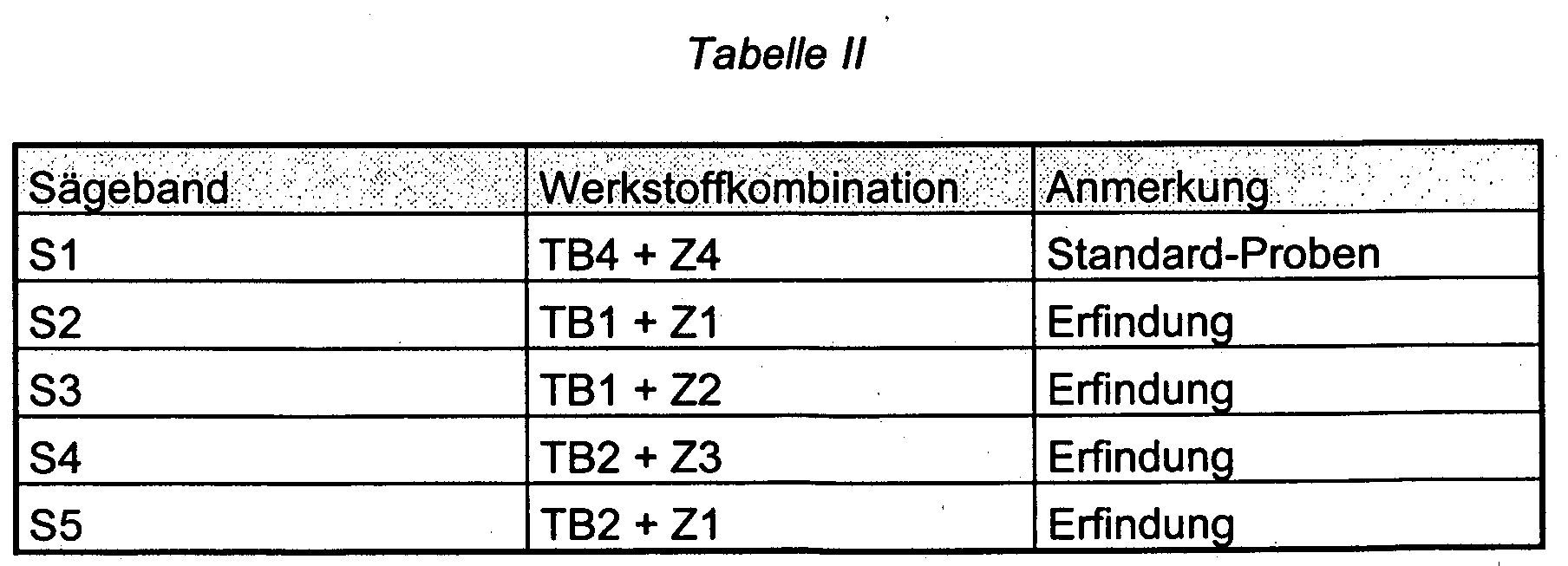
- Table II below shows the material combinations for five bandsaw blades S1 to S5, of which samples were examined with regard to their structural stability and flexural fatigue strength.
- the sample 5 is against each in a manner not shown in the drawing Movement in relation to the pendulum table 2 secured.
- Sheet metal strips of the dimension were used to determine the fatigue strength 8 x 1.35 x 80 mm and 20 x 1.5 x 80 mm at one temperature from 1180 ° C under protective gas, annealed and quenched as well as then tempered three times at 560 ° C.
- the main components of the spring rocker are a swing beam, who is held in a fixed camp at one end and at the other end by an adjustable double eccentric is driven, and two via handwheels parallel height-adjustable crossbeams (base plates) of an upper one and a lower test floor.
- the lifting height of the eccentric can be adjusted in steps of 1.5 mm, set between 0 and 36 mm, the stroke amplitude is linear from 0 (fixed bearing) to the maximum value at the eccentric.
- On the lower one and the upper test floor each have up to six sample shots with 16 sample places next to each other.
- test specimens are loosely inserted into the receptacles at both ends and form free-standing flexible beams of free length L on two bearing points
- the force distribution to generate a corresponding bending moment was done by a central deflection, for which purpose over each individual sample a contact piece made of hard metal and positioned exactly in the middle was.
- test stress was calculated according to a known formula from the measured deflection and the band dimensions for an elastic modulus of 206,000 N / mm 2 .
- FIG. 3 shows the number of the respective load changes in dependence on the ratio of the contents of tungsten and molybdenum in the area from about 0.6 to about 1.5 again. A maximum is clearly shown a ratio of 1.0.
- the service life of a conventional saw band S1 (standard sample) was set at 100% with an initial cutting performance of 20 cm 2 / min and the service life of the saw band S2 according to the invention was 280%.
- the contact pressure of the saw band was increased to such an extent that an initial cutting performance of 35 cm 2 / min resulted.
- the tool life in this test was 230%.
- Further tests with the saw bands S3 resulted in a service life of 340% with an initial cutting performance of 35 cm 2 / min and a service life of 345% with the saw band S4, while the saw band S5 according to the invention achieved a service life of 295 at an initial speed of 35 cm 2 / min % reached.
- the service life of the conventional saw band S1 was only 58% with the aforementioned initial cutting performance. This is due to the occurrence of friction martensite and the resulting fatigue fractures in the back of the belt.
Abstract
Description
- Fig. 1
- die perspektivische Darstellung einer Maschine zum Prüfen der Bandrückenbeständigkeit,
- Fig. 2
- eine grafische Darstellung des Entstehens von Reibmartensit in Abhängigkeit von dem Anpreßdruck und
- Fig. 3
- die Abhängigkeit der Biegewechselfestigkeit von dem Verhältnis der Gehalte an Wolfram und Molybdän im Trägerbandwerkstoff.

Claims (7)
- Bimetall-Sägeband mit einem Schneidteil aus einem Schnellarbeitsstahl, gekennzeichnet durch ein Trägerband aus einem Stahl mit
0,25 bis 0,35% Kohlenstoff 0,3 bis 0,5% Silizium 0,8 bis 1,5% Mangan 1,0 bis 2,0% Molybdän 1,5 bis 3,5% Chrom 0,5 bis 1,5% Nickel 0,5 bis 2,5% Wolfram 0,15 bis 0,30% Vanadium 0,05 bis 0,10% Niob 0,05 bis 1,0% Kupfer bis 0,2% Aluminium bis 1% Kobalt, - Sägeband, dadurch gekennzeichnet, daß das Trägerband aus einem Stahl mit
0,25 bis 0,35% Kohlenstoff 0,3 bis 0,5% Silizium 0,8 bis 1,5% Mangan 1,2 bis 1,8% Molybdän 1,5 bis 2,5% Chrom 0,5 bis 1,5% Nickel 1,2 bis 1,8% Wolfram 0,1 bis 0,8% Kupfer 0,15 bis 0,30% Vanadium 0,05 bis 0,10% Niob, - Sägeband nach Anspruch 1 oder 2, dadurch gekennzeichnet, daß mindestens die Zähne des Schneidteils aus einem Stahl mit
1,0 bis 2,0% Kohlenstoff 3 bis 6% Chrom 1 bis 5% Vanadium 3 bis 10% Molybdän 4 bis 10% Wolfram 4 bis 10% Kobalt bis 1% Silizium bis 1% Mangan bis 0,5 % Niob bis 0,5% Stickstoff, - Sägeband nach einem der Ansprüche 1 bis 3, dadurch gekennzeichnet, daß zumindest die Zähne des Schneidteils aus einem Stahl mit
1,0 bis 1,8% Kohlenstoff 3,4 bis 4,4% Chrom 1,6 bis 4,0% Vanadium 3,2 bis 6,5% Molybdän 6 bis 10% Wolfram 4 bis 10% Kobalt, - Sägeband nach einem der Ansprüche 1 bis 4, dadurch gekennzeichnet, daß das Verhältnis der Gehalte an Wolfram und Molybdän zueinander 0,6 bis 1,5 beträgt.
- Sägeband nach einem der Ansprüche 1 bis 5, dadurch gekennzeichnet, daß der Schneidteil pulvermetallurgisch hergestellt ist.
- Verwendung eines Sägebandes nach einem der Ansprüche 1 bis 6 in Verbindung mit einer auf den Bandrücken wirkenden Anpressrolle.
Applications Claiming Priority (2)
| Application Number | Priority Date | Filing Date | Title |
|---|---|---|---|
| DE2002105403 DE10205403B4 (de) | 2002-02-09 | 2002-02-09 | Bimetall-Sägeband |
| DE10205403 | 2002-02-09 |
Publications (2)
| Publication Number | Publication Date |
|---|---|
| EP1340830A1 true EP1340830A1 (de) | 2003-09-03 |
| EP1340830B1 EP1340830B1 (de) | 2005-01-26 |
Family
ID=27634835
Family Applications (1)
| Application Number | Title | Priority Date | Filing Date |
|---|---|---|---|
| EP03002794A Expired - Fee Related EP1340830B1 (de) | 2002-02-09 | 2003-02-07 | Bimetall-Sägeband |
Country Status (5)
| Country | Link |
|---|---|
| US (1) | US6869692B2 (de) |
| EP (1) | EP1340830B1 (de) |
| AR (1) | AR038675A1 (de) |
| AT (1) | ATE287973T1 (de) |
| DE (1) | DE10205403B4 (de) |
Cited By (1)
| Publication number | Priority date | Publication date | Assignee | Title |
|---|---|---|---|---|
| EP1437190A2 (de) * | 2002-12-12 | 2004-07-14 | Stahlwerk Ergste Westig GmbH | Verwendung einer Chrom-Stahllegierung |
Families Citing this family (8)
| Publication number | Priority date | Publication date | Assignee | Title |
|---|---|---|---|---|
| FI116044B (fi) * | 2002-05-28 | 2005-09-15 | Metso Paper Inc | Paperi- tai kartonkirainan pituussuuntaisessa leikkauksessa käytettävä terä |
| CN100374609C (zh) * | 2006-01-25 | 2008-03-12 | 周向儒 | 铬钢系高速钢及其热处理工艺 |
| US20100011594A1 (en) * | 2008-07-15 | 2010-01-21 | Wysk Mark J | Composite Saw Blades |
| AT507956B1 (de) * | 2009-02-16 | 2011-01-15 | Boehler Edelstahl Gmbh & Co Kg | Bimetallsäge |
| CN104451421B (zh) * | 2013-09-13 | 2017-01-11 | 宝钢特钢有限公司 | 一种高强韧性双金属带锯条背材用钢及其制备方法 |
| BR102016001063B1 (pt) * | 2016-01-18 | 2021-06-08 | Amsted Maxion Fundição E Equipamentos Ferroviários S/A | liga de aço para componentes ferroviários, e processo de obtenção de uma liga de aço para componentes ferroviários |
| CN106424941A (zh) * | 2016-11-23 | 2017-02-22 | 江苏爱利德科技有限公司 | 一种高强韧性双金属锯条及其制造工艺 |
| PL236222B1 (pl) * | 2018-04-11 | 2020-12-28 | Klepuszewska Grazyna Qsgs Tech | Stal na monolityczne i bimetaliczne piły taśmowe do drewna |
Citations (6)
| Publication number | Priority date | Publication date | Assignee | Title |
|---|---|---|---|---|
| JPS5837156A (ja) * | 1981-08-31 | 1983-03-04 | Daido Steel Co Ltd | 胴材 |
| JPH0259211A (ja) * | 1988-08-20 | 1990-02-28 | Hitachi Koki Co Ltd | 電動工具のソーブレード及びその製造方法 |
| EP0452526A1 (de) * | 1988-10-21 | 1991-10-23 | Hitachi Metals, Ltd. | Werkstoff mit hoher Dauerschwingfestigkeit für Trägerbänder von Sägeblättern |
| EP0569349A1 (de) * | 1992-05-06 | 1993-11-10 | BÖHLER YBBSTALWERKE Ges.m.b.H. | Bi-Metall-Bandrohling sowie daraus gefertigtes Bi-Metall-Sägeblatt |
| EP0566560B1 (de) * | 1992-04-08 | 1996-01-10 | BÖHLER YBBSTALWERKE Ges.m.b.H. | Werkstoff für den spanabhebenden Bereich von Bi-Metall-Sägeblattern |
| DE20002593U1 (de) * | 1999-02-15 | 2000-08-17 | Boehler Ybbstal Band Ges M B H | Vormaterial für Sägebänder oder Sägeblätter |
Family Cites Families (9)
| Publication number | Priority date | Publication date | Assignee | Title |
|---|---|---|---|---|
| JPS528918A (en) * | 1975-07-11 | 1977-01-24 | Hitachi Metals Ltd | Metal band saw body with high fatigue strength |
| JPS637351A (ja) * | 1986-06-27 | 1988-01-13 | Daido Steel Co Ltd | メタルバンドソ−の胴材 |
| AT391826B (de) * | 1987-12-04 | 1990-12-10 | Boehler Gmbh | Bi-metallband fuer metallsaegen |
| AT396560B (de) * | 1992-05-06 | 1993-10-25 | Boehler Ybbstalwerke | Metallsägeblatt mit hoher biegewechselfestigkeit und hoher schnittleistung |
| US5863358A (en) * | 1993-12-09 | 1999-01-26 | Uddeholm Strip Steel Aktiebolag | Steel alloy saw blade backing strip |
| US5417777A (en) * | 1994-02-22 | 1995-05-23 | American Saw & Mfg. Company | Alloy for backing steel of a bimetallic band saw blade |
| JP4144094B2 (ja) * | 1999-01-28 | 2008-09-03 | 日立金属株式会社 | メタルバンドソー用刃材 |
| DE29914569U1 (de) * | 1999-08-19 | 1999-12-23 | Bender Dieter | Stichsägeblatt |
| DE10202770B4 (de) * | 2002-01-25 | 2006-06-14 | Stahlwerk Ergste Westig Gmbh | Bimetall-Sägeband |
-
2002
- 2002-02-09 DE DE2002105403 patent/DE10205403B4/de not_active Expired - Fee Related
-
2003
- 2003-02-03 AR ARP030100331 patent/AR038675A1/es active IP Right Grant
- 2003-02-06 US US10/360,199 patent/US6869692B2/en not_active Expired - Fee Related
- 2003-02-07 EP EP03002794A patent/EP1340830B1/de not_active Expired - Fee Related
- 2003-02-07 AT AT03002794T patent/ATE287973T1/de active
Patent Citations (6)
| Publication number | Priority date | Publication date | Assignee | Title |
|---|---|---|---|---|
| JPS5837156A (ja) * | 1981-08-31 | 1983-03-04 | Daido Steel Co Ltd | 胴材 |
| JPH0259211A (ja) * | 1988-08-20 | 1990-02-28 | Hitachi Koki Co Ltd | 電動工具のソーブレード及びその製造方法 |
| EP0452526A1 (de) * | 1988-10-21 | 1991-10-23 | Hitachi Metals, Ltd. | Werkstoff mit hoher Dauerschwingfestigkeit für Trägerbänder von Sägeblättern |
| EP0566560B1 (de) * | 1992-04-08 | 1996-01-10 | BÖHLER YBBSTALWERKE Ges.m.b.H. | Werkstoff für den spanabhebenden Bereich von Bi-Metall-Sägeblattern |
| EP0569349A1 (de) * | 1992-05-06 | 1993-11-10 | BÖHLER YBBSTALWERKE Ges.m.b.H. | Bi-Metall-Bandrohling sowie daraus gefertigtes Bi-Metall-Sägeblatt |
| DE20002593U1 (de) * | 1999-02-15 | 2000-08-17 | Boehler Ybbstal Band Ges M B H | Vormaterial für Sägebänder oder Sägeblätter |
Non-Patent Citations (2)
| Title |
|---|
| PATENT ABSTRACTS OF JAPAN vol. 007, no. 118 (C - 167) 21 May 1983 (1983-05-21) * |
| PATENT ABSTRACTS OF JAPAN vol. 014, no. 231 (M - 0974) 16 May 1990 (1990-05-16) * |
Cited By (2)
| Publication number | Priority date | Publication date | Assignee | Title |
|---|---|---|---|---|
| EP1437190A2 (de) * | 2002-12-12 | 2004-07-14 | Stahlwerk Ergste Westig GmbH | Verwendung einer Chrom-Stahllegierung |
| EP1437190A3 (de) * | 2002-12-12 | 2007-07-25 | Stahlwerk Ergste Westig GmbH | Verwendung einer Chrom-Stahllegierung |
Also Published As
| Publication number | Publication date |
|---|---|
| ATE287973T1 (de) | 2005-02-15 |
| US6869692B2 (en) | 2005-03-22 |
| US20030152477A1 (en) | 2003-08-14 |
| EP1340830B1 (de) | 2005-01-26 |
| DE10205403B4 (de) | 2007-03-29 |
| AR038675A1 (es) | 2005-01-26 |
| DE10205403A1 (de) | 2003-09-04 |
Similar Documents
| Publication | Publication Date | Title |
|---|---|---|
| EP0319511B1 (de) | Bi-Metallband für Metallsägen | |
| DE2732572C2 (de) | Pulvermischung zur Herstellung von Sinterkörpern | |
| DE602005003979T2 (de) | Stahlband für eine Austauschklinge und dessen Herstellung | |
| EP1331056B1 (de) | Bimetall-Sägeband | |
| DE2722972C2 (de) | Nach dem Pulvermetallurgieverfahren hergestellter, Stickstoff enthaltender Schnelldrehstahl | |
| EP1035942B1 (de) | Verfahren zum herstellen von sägebändern | |
| DE3041565C2 (de) | ||
| EP2662168A1 (de) | Sägeblatt mit einem pulvermetallurgisch hergestellten Schneidteil | |
| EP0835331B1 (de) | Basismaterial für die herstellung von stammblättern für kreissägen, trennscheiben, gattersägen sowie schneid- und schabvorrichtungen | |
| EP1340830B1 (de) | Bimetall-Sägeband | |
| EP3976302B1 (de) | Schneidglied für eine sägekette und verfahren zu deren herstellung | |
| EP1249511A1 (de) | PM-Schnellarbeitsstahl mit hoher Warmfestigkeit | |
| AT402482B (de) | Stanzmesser für stanzwerkzeuge mit gekrümmtem schnitt | |
| DE19505955B4 (de) | Nichtrostender Bandstahlen hoher Festigkeit und Zähigkeit und Verfahren zum Herstellen desselben | |
| DE112008003146T5 (de) | Stahl für eine Induktionshärtung mit einer hervorragenden Kaltverarbeitungsfähigkeit, Rollglied, das aus einem derartigen Stahl ausgebildet ist, und Bewegungsführungsvorrichtung, die ein derartiges Rollglied verwendet | |
| EP0640693A1 (de) | Papiermesser und Verfahren zu dessen Herstellung | |
| DE19531260C5 (de) | Verfahren zur Herstellung eines Warmarbeitsstahls | |
| DE102005013538A1 (de) | Plattenförmiges Element für einen Riemen in einem kontinuierlich variablen Getriebe des Riementyps | |
| DE4232115C2 (de) | Verwendung eines austenitischen Stahls als hochbelastbares Befestigungselement | |
| DE2923532B1 (de) | Verwendung eines ferritischen rostfreien Stahls fuer in geschweisstem Zustand ohne Waermenachbehandlung gegen interkristalline Korrosion bestaendige Gegenstaende | |
| DE1927428C2 (de) | Verwendung eines Stahlbandes aus einem Stahl mit ausreichend gutem Karbid-Lösungsvermögen zur Herstellung von Sägeblättern. - | |
| EP0060577B2 (de) | Turbinenschaufelwerkstoff hoher Festigkeit gegen Korrosionsermüdung, Verfahren zu dessen Herstellung und seine Verwendung | |
| AT500728B1 (de) | Schneidwerkzeug | |
| DE2014854A1 (de) | Kettensägeeinheit | |
| DE2251894A1 (de) | Waelzlagerstahl |
Legal Events
| Date | Code | Title | Description |
|---|---|---|---|
| PUAI | Public reference made under article 153(3) epc to a published international application that has entered the european phase |
Free format text: ORIGINAL CODE: 0009012 |
|
| AK | Designated contracting states |
Kind code of ref document: A1 Designated state(s): AT BE BG CH CY CZ DE DK EE ES FI FR GB GR HU IE IT LI LU MC NL PT SE SI SK TR |
|
| AX | Request for extension of the european patent |
Extension state: AL LT LV MK RO |
|
| 17P | Request for examination filed |
Effective date: 20040227 |
|
| GRAP | Despatch of communication of intention to grant a patent |
Free format text: ORIGINAL CODE: EPIDOSNIGR1 |
|
| AKX | Designation fees paid |
Designated state(s): AT GB SE |
|
| REG | Reference to a national code |
Ref country code: DE Ref legal event code: 8566 |
|
| GRAS | Grant fee paid |
Free format text: ORIGINAL CODE: EPIDOSNIGR3 |
|
| GRAA | (expected) grant |
Free format text: ORIGINAL CODE: 0009210 |
|
| AK | Designated contracting states |
Kind code of ref document: B1 Designated state(s): AT GB SE |
|
| REG | Reference to a national code |
Ref country code: GB Ref legal event code: FG4D Free format text: NOT ENGLISH |
|
| REG | Reference to a national code |
Ref country code: IE Ref legal event code: FG4D Free format text: GERMAN |
|
| REG | Reference to a national code |
Ref country code: SE Ref legal event code: TRGR |
|
| GBT | Gb: translation of ep patent filed (gb section 77(6)(a)/1977) |
Effective date: 20050420 |
|
| PLBE | No opposition filed within time limit |
Free format text: ORIGINAL CODE: 0009261 |
|
| STAA | Information on the status of an ep patent application or granted ep patent |
Free format text: STATUS: NO OPPOSITION FILED WITHIN TIME LIMIT |
|
| 26N | No opposition filed |
Effective date: 20051027 |
|
| PGFP | Annual fee paid to national office [announced via postgrant information from national office to epo] |
Ref country code: SE Payment date: 20160222 Year of fee payment: 14 Ref country code: AT Payment date: 20160218 Year of fee payment: 14 Ref country code: GB Payment date: 20160222 Year of fee payment: 14 |
|
| REG | Reference to a national code |
Ref country code: SE Ref legal event code: EUG |
|
| REG | Reference to a national code |
Ref country code: AT Ref legal event code: MM01 Ref document number: 287973 Country of ref document: AT Kind code of ref document: T Effective date: 20170207 |
|
| GBPC | Gb: european patent ceased through non-payment of renewal fee |
Effective date: 20170207 |
|
| PG25 | Lapsed in a contracting state [announced via postgrant information from national office to epo] |
Ref country code: AT Free format text: LAPSE BECAUSE OF NON-PAYMENT OF DUE FEES Effective date: 20170207 |
|
| PG25 | Lapsed in a contracting state [announced via postgrant information from national office to epo] |
Ref country code: SE Free format text: LAPSE BECAUSE OF NON-PAYMENT OF DUE FEES Effective date: 20170208 |
|
| PG25 | Lapsed in a contracting state [announced via postgrant information from national office to epo] |
Ref country code: GB Free format text: LAPSE BECAUSE OF NON-PAYMENT OF DUE FEES Effective date: 20170207 |