EP1340830A1 - Bimetallic saw band - Google Patents
Bimetallic saw band Download PDFInfo
- Publication number
- EP1340830A1 EP1340830A1 EP03002794A EP03002794A EP1340830A1 EP 1340830 A1 EP1340830 A1 EP 1340830A1 EP 03002794 A EP03002794 A EP 03002794A EP 03002794 A EP03002794 A EP 03002794A EP 1340830 A1 EP1340830 A1 EP 1340830A1
- Authority
- EP
- European Patent Office
- Prior art keywords
- saw band
- molybdenum
- steel
- tungsten
- vanadium
- Prior art date
- Legal status (The legal status is an assumption and is not a legal conclusion. Google has not performed a legal analysis and makes no representation as to the accuracy of the status listed.)
- Granted
Links
Images


Classifications
-
- C—CHEMISTRY; METALLURGY
- C22—METALLURGY; FERROUS OR NON-FERROUS ALLOYS; TREATMENT OF ALLOYS OR NON-FERROUS METALS
- C22C—ALLOYS
- C22C38/00—Ferrous alloys, e.g. steel alloys
- C22C38/18—Ferrous alloys, e.g. steel alloys containing chromium
- C22C38/40—Ferrous alloys, e.g. steel alloys containing chromium with nickel
- C22C38/42—Ferrous alloys, e.g. steel alloys containing chromium with nickel with copper
-
- B—PERFORMING OPERATIONS; TRANSPORTING
- B23—MACHINE TOOLS; METAL-WORKING NOT OTHERWISE PROVIDED FOR
- B23D—PLANING; SLOTTING; SHEARING; BROACHING; SAWING; FILING; SCRAPING; LIKE OPERATIONS FOR WORKING METAL BY REMOVING MATERIAL, NOT OTHERWISE PROVIDED FOR
- B23D61/00—Tools for sawing machines or sawing devices; Clamping devices for these tools
- B23D61/12—Straight saw blades; Strap saw blades
- B23D61/127—Straight saw blades; Strap saw blades of special material
-
- C—CHEMISTRY; METALLURGY
- C22—METALLURGY; FERROUS OR NON-FERROUS ALLOYS; TREATMENT OF ALLOYS OR NON-FERROUS METALS
- C22C—ALLOYS
- C22C38/00—Ferrous alloys, e.g. steel alloys
- C22C38/04—Ferrous alloys, e.g. steel alloys containing manganese
-
- C—CHEMISTRY; METALLURGY
- C22—METALLURGY; FERROUS OR NON-FERROUS ALLOYS; TREATMENT OF ALLOYS OR NON-FERROUS METALS
- C22C—ALLOYS
- C22C38/00—Ferrous alloys, e.g. steel alloys
- C22C38/18—Ferrous alloys, e.g. steel alloys containing chromium
- C22C38/22—Ferrous alloys, e.g. steel alloys containing chromium with molybdenum or tungsten
-
- C—CHEMISTRY; METALLURGY
- C22—METALLURGY; FERROUS OR NON-FERROUS ALLOYS; TREATMENT OF ALLOYS OR NON-FERROUS METALS
- C22C—ALLOYS
- C22C38/00—Ferrous alloys, e.g. steel alloys
- C22C38/18—Ferrous alloys, e.g. steel alloys containing chromium
- C22C38/24—Ferrous alloys, e.g. steel alloys containing chromium with vanadium
-
- C—CHEMISTRY; METALLURGY
- C22—METALLURGY; FERROUS OR NON-FERROUS ALLOYS; TREATMENT OF ALLOYS OR NON-FERROUS METALS
- C22C—ALLOYS
- C22C38/00—Ferrous alloys, e.g. steel alloys
- C22C38/18—Ferrous alloys, e.g. steel alloys containing chromium
- C22C38/30—Ferrous alloys, e.g. steel alloys containing chromium with cobalt
-
- C—CHEMISTRY; METALLURGY
- C22—METALLURGY; FERROUS OR NON-FERROUS ALLOYS; TREATMENT OF ALLOYS OR NON-FERROUS METALS
- C22C—ALLOYS
- C22C38/00—Ferrous alloys, e.g. steel alloys
- C22C38/18—Ferrous alloys, e.g. steel alloys containing chromium
- C22C38/36—Ferrous alloys, e.g. steel alloys containing chromium with more than 1.7% by weight of carbon
-
- C—CHEMISTRY; METALLURGY
- C22—METALLURGY; FERROUS OR NON-FERROUS ALLOYS; TREATMENT OF ALLOYS OR NON-FERROUS METALS
- C22C—ALLOYS
- C22C38/00—Ferrous alloys, e.g. steel alloys
- C22C38/18—Ferrous alloys, e.g. steel alloys containing chromium
- C22C38/40—Ferrous alloys, e.g. steel alloys containing chromium with nickel
- C22C38/44—Ferrous alloys, e.g. steel alloys containing chromium with nickel with molybdenum or tungsten
-
- C—CHEMISTRY; METALLURGY
- C22—METALLURGY; FERROUS OR NON-FERROUS ALLOYS; TREATMENT OF ALLOYS OR NON-FERROUS METALS
- C22C—ALLOYS
- C22C38/00—Ferrous alloys, e.g. steel alloys
- C22C38/18—Ferrous alloys, e.g. steel alloys containing chromium
- C22C38/40—Ferrous alloys, e.g. steel alloys containing chromium with nickel
- C22C38/46—Ferrous alloys, e.g. steel alloys containing chromium with nickel with vanadium
-
- C—CHEMISTRY; METALLURGY
- C22—METALLURGY; FERROUS OR NON-FERROUS ALLOYS; TREATMENT OF ALLOYS OR NON-FERROUS METALS
- C22C—ALLOYS
- C22C38/00—Ferrous alloys, e.g. steel alloys
- C22C38/18—Ferrous alloys, e.g. steel alloys containing chromium
- C22C38/40—Ferrous alloys, e.g. steel alloys containing chromium with nickel
- C22C38/48—Ferrous alloys, e.g. steel alloys containing chromium with nickel with niobium or tantalum
-
- Y—GENERAL TAGGING OF NEW TECHNOLOGICAL DEVELOPMENTS; GENERAL TAGGING OF CROSS-SECTIONAL TECHNOLOGIES SPANNING OVER SEVERAL SECTIONS OF THE IPC; TECHNICAL SUBJECTS COVERED BY FORMER USPC CROSS-REFERENCE ART COLLECTIONS [XRACs] AND DIGESTS
- Y10—TECHNICAL SUBJECTS COVERED BY FORMER USPC
- Y10T—TECHNICAL SUBJECTS COVERED BY FORMER US CLASSIFICATION
- Y10T428/00—Stock material or miscellaneous articles
- Y10T428/12—All metal or with adjacent metals
- Y10T428/12493—Composite; i.e., plural, adjacent, spatially distinct metal components [e.g., layers, joint, etc.]
- Y10T428/12771—Transition metal-base component
- Y10T428/12861—Group VIII or IB metal-base component
- Y10T428/12951—Fe-base component
- Y10T428/12958—Next to Fe-base component
- Y10T428/12965—Both containing 0.01-1.7% carbon [i.e., steel]
-
- Y—GENERAL TAGGING OF NEW TECHNOLOGICAL DEVELOPMENTS; GENERAL TAGGING OF CROSS-SECTIONAL TECHNOLOGIES SPANNING OVER SEVERAL SECTIONS OF THE IPC; TECHNICAL SUBJECTS COVERED BY FORMER USPC CROSS-REFERENCE ART COLLECTIONS [XRACs] AND DIGESTS
- Y10—TECHNICAL SUBJECTS COVERED BY FORMER USPC
- Y10T—TECHNICAL SUBJECTS COVERED BY FORMER US CLASSIFICATION
- Y10T428/00—Stock material or miscellaneous articles
- Y10T428/12—All metal or with adjacent metals
- Y10T428/12493—Composite; i.e., plural, adjacent, spatially distinct metal components [e.g., layers, joint, etc.]
- Y10T428/12771—Transition metal-base component
- Y10T428/12861—Group VIII or IB metal-base component
- Y10T428/12951—Fe-base component
- Y10T428/12972—Containing 0.01-1.7% carbon [i.e., steel]
- Y10T428/12979—Containing more than 10% nonferrous elements [e.g., high alloy, stainless]
-
- Y—GENERAL TAGGING OF NEW TECHNOLOGICAL DEVELOPMENTS; GENERAL TAGGING OF CROSS-SECTIONAL TECHNOLOGIES SPANNING OVER SEVERAL SECTIONS OF THE IPC; TECHNICAL SUBJECTS COVERED BY FORMER USPC CROSS-REFERENCE ART COLLECTIONS [XRACs] AND DIGESTS
- Y10—TECHNICAL SUBJECTS COVERED BY FORMER USPC
- Y10T—TECHNICAL SUBJECTS COVERED BY FORMER US CLASSIFICATION
- Y10T83/00—Cutting
- Y10T83/929—Tool or tool with support
- Y10T83/9319—Toothed blade or tooth therefor
Landscapes
- Chemical & Material Sciences (AREA)
- Engineering & Computer Science (AREA)
- Mechanical Engineering (AREA)
- Materials Engineering (AREA)
- Metallurgy (AREA)
- Organic Chemistry (AREA)
- Sawing (AREA)
- Heat Treatment Of Articles (AREA)
- Lubricants (AREA)
- Belt Conveyors (AREA)
- Manufacture Of Alloys Or Alloy Compounds (AREA)
Abstract
Description
Die Erfindung bezieht sich auf ein Bimetall-Sägeband, bei dem zumindest die Zahnspitzen aus einem verschleißfesten Stahl und das Trägerband aus einem vergleichsweise zähen Stahl bestehen.The invention relates to a bimetal saw band, in which at least the tooth tips made of wear-resistant steel and the carrier tape a comparatively tough steel.
Sägebänder, einschließlich Stichsägen, müssen eine hohe Formbeständigkeit sowie eine hohe Verschleißfestigkeit besitzen und der hohen Beanspruchung durch Druck-, Biege- und Schubkräfte auch bei den nicht unerheblichen Temperaturen gewachsen sein, die sich aus der Reibung zwischen Sägeband und Schneidgut ergeben. Dies gilt namentlich für Sägebänder, die mit hoher Geschwindigkeit umlaufen und beim Umlenken um 180° einer starken Biegung unterliegen.Saw bands, including jigsaws, need high dimensional stability as well as high wear resistance and high stress due to pressure, bending and shear forces even with the not insignificant ones Temperatures have grown due to the friction between Saw band and material to be cut result. This applies in particular to saw bands, that rotate at high speed and one when deflected by 180 ° subject to strong bending.
Da es schwierig ist, die erforderlichen Eigenschaften in einem einzigen Werkstoff zu vereinigen, bestehen Bimetall-Sägebänder heutzutage üblicherweise aus einem verhältnismäßig zähen Trägerband mit hoher Biegewechselfestigkeit und einem ebenfalls bandförmigen Schneidteil aus einem Schnellarbeitsstahl mit geringerer Zähigkeit, aber hoher Verschleißfestigkeit. Das Schneidband ist dabei so breit, daß sich daraus zumindest die Zahnspitzen des Sägebandes oder -blattes oder auch die Schneidzähne insgesamt herausarbeiten lassen.Because it is difficult to combine the required properties in one Bimetallic bandsaw blades usually exist today to combine material from a relatively tough carrier tape with high flexural fatigue strength and also a band-shaped cutting part from one High-speed steel with lower toughness but high wear resistance. The cutting band is so wide that at least the tooth tips result from it of the saw band or blade or the cutting teeth as a whole let work out.
Aus der EP 0 569 346 A1 ist auch bereits ein Bimetall-Sägeband oder -blatt aus einem Stahl-Trägerband mit 0,20 bis 0,40% Kohlenstoff, 2,5 bis 5,0% Chrom, 2,0 bis 3,0% Molybdän, 0,03 bis 0,04% Vanadium sowie als Kornfeinungsmittel insgesamt unter 0,01% Niob und Titan einerseits sowie einem Schneidband aus einem Schnellarbeitsstahl mit 0,65 bis 1,8% Kohlenstoff, 3,0 bis 6,0% Chrom, 4,0 bis 12,0% Molybdän und 0,5 bis 5,0% Vanadium bekannt. Besonderes Kennzeichen dieses Sägebands ist unter dem Gesichtspunkt einer ausreichenden Dauerwechselfestigkeit bzw. Biegewechselfestigkeit die gleichzeitige Anwesenheit von Chrom, Vanadium und Molybdän in beiden Werkstoffen sowie die Begrenzung des Gesamtgehaltes an Niob und Titan im Trägerband auf höchstens 0,01%. Zur Verbesserung der Schweißbarkeit enthalten beide Werkstoffe des Sägebandes zudem Aluminium, und zwar bis 2,0% im Schneidteil und bis 0,15% im Trägerband.EP 0 569 346 A1 has already disclosed a bimetallic band or blade from a steel carrier tape with 0.20 to 0.40% carbon, 2.5 to 5.0% Chromium, 2.0 to 3.0% molybdenum, 0.03 to 0.04% vanadium and as a grain refiner a total of less than 0.01% niobium and titanium on the one hand and one High-speed steel cutting tape with 0.65 to 1.8% carbon, 3.0 to 6.0% chromium, 4.0 to 12.0% molybdenum and 0.5 to 5.0% vanadium known. A special feature of this saw band is from the point of view sufficient fatigue strength or fatigue strength the simultaneous presence of chromium, vanadium and molybdenum in both materials as well as the limitation of the total content Niobium and titanium in the carrier tape to a maximum of 0.01%. To improve the Both materials of the saw band also contain aluminum, up to 2.0% in the cutting part and up to 0.15% in the carrier tape.
Des weiteren beschreibt die japanische Offenlegungsschrift 63-007 351 ein Bimetall-Sägeband mit hoher Zähigkeit und Dauerfestigkeit aus einem niedrig legierten Stahl mit 0,25 bis 0,50% Kohlenstoff, unter 1,5% Nickel, 2,00 bis 6,00% Chrom, 0,20 bis 1,00% Vanadium, 0,20 bis 1,00% Molybdän und/oder unter 1,50% Wolfram, unter 0,30% Silizium, unter 0,50% Mangan, unter 0,015% Phosphor und unter 0,005% Schwefel bei insgesamt 0,20 bis 1,00% Molybdän und dem halben Wolframgehalt, unter 0,0015% Sauerstoff, 0,02 bis 0,20% Niob und/oder 0,02 bis 0,20% Titan sowie einem Schneidteil aus einem Hochgeschwindigkeitsstahl.Furthermore, Japanese laid-open specification 63-007 351 describes a Bimetal saw band with high toughness and fatigue strength from a low alloy steel with 0.25 to 0.50% carbon, under 1.5% nickel, 2.00 up to 6.00% chromium, 0.20 to 1.00% vanadium, 0.20 to 1.00% molybdenum and / or below 1.50% tungsten, below 0.30% silicon, below 0.50% manganese, below 0.015% phosphorus and below 0.005% sulfur at a total of 0.20 to 1.00% molybdenum and half the tungsten content, under 0.0015% oxygen, 0.02 to 0.20% niobium and / or 0.02 to 0.20% titanium and a cutting part from a high speed steel.
Weiterhin ist aus der US-Patentschrift 4 058 650 ein Trägerbandstahl mit
0,20 bis 0,33% Kohlenstoff, bis 1,5% Silizium, bis 1,5% Mangan, 3,5 bis
6,5% Chrom, 0,05 bis 0,40% Vanadium, 0,05 bis 0,10% Aluminium, 0,02 bis
0,30% Niob, 1,0 bis 3,0% Molybdän und/oder bis 4,0% Wolfram sowie einem
Gesamtgehalt an Molybdän und dem halben Wolframgehalt von 1,0 bis
3,0% bekannt, der zur Verbesserung der Dauerfestigkeit und Zähigkeit des
Grundgefüges noch bis 1,4% Kobalt und bis 1,5% Nickel enthalten kann.
Dieser Trägerbandwerkstoff soll sich durch eine geringe Entkohlung und
Gefügestabilität beim Verschweißen mit dem Schneidteil auszeichnen und
weder seine Zähigkeit bei einer Wärmebehandlung des Schneidteils verlieren
noch beim Anlassen mit höheren Temperaturen im Hinblick auf die Dauerfestigkeit
eine Härte von etwa HRC 50 gewährleisten. Furthermore, a carrier steel strip is from US Pat. No. 4,058,650
0.20 to 0.33% carbon, up to 1.5% silicon, up to 1.5% manganese, 3.5 to
6.5% chromium, 0.05 to 0.40% vanadium, 0.05 to 0.10% aluminum, 0.02 to
0.30% niobium, 1.0 to 3.0% molybdenum and / or to 4.0% tungsten and one
Total molybdenum content and half the tungsten content from 1.0 to
3.0% known to improve the fatigue strength and toughness of the
Basic structure can still contain up to 1.4% cobalt and up to 1.5% nickel.
This carrier tape material is said to have low decarburization and
Mark structural stability when welding with the cutting part and
neither lose its toughness when the cutting part is heat treated
even when tempering at higher temperatures with regard to fatigue strength
ensure a hardness of approximately
Ein besonderes, von der Praxis bislang wenig beachtetes Problem besteht bei Sägebändern darin, daß die Schnittleistung nicht nur von der Bandgeschwindigkeit (Umlaufgeschwindigkeit) abhängig ist, sondern auch von der Vorschubgeschwindigkeit des Sägebandes in Richtung Schneidgut, d.h. von der Anpreßkraft. Die mit steigender Schnittgeschwindigkeit zunehmende Wärmeentwicklung begrenzt jedoch die mögliche Erhöhung der Schnittgeschwindigkeit im Hinblick auf die begrenzte Warmfestigkeit der Schneidzähne, so daß sich die Bandgeschwindigkeit nicht beliebig erhöhen läßt. Eine Verbesserung der Schnittleistung läßt sich jedoch mit einem höheren Vorschub bzw. Schneiddruck erreichen, weil dann die Sägezähne tiefer in den zu schneidenden Werkstoff eindringen, sich dann die beim Schneiden entstehende Reibwärme besser verteilt und in den zu schneidenden Werkstoff abgeleitet wird. Um einen verlauffreien bzw. geraden Sägeschnitt zu gewährleisten, ist zudem eine dem erhöhten Vorschub entsprechende höhere Blattspannung erforderlich, die nur möglich ist, wenn der Trägerbandwerkstoff eine ausreichende Biegewechselfestigkeit besitzt.There is a special problem that has so far been neglected in practice In the case of saw bands, the cutting performance is not only dependent on the band speed (Circulation speed) depends, but also on the Feed speed of the saw band towards the material to be cut, i.e. of the contact pressure. The increasing with increasing cutting speed However, heat development limits the possible increase in the cutting speed with regard to the limited heat resistance of the cutting teeth, so that the belt speed cannot be increased arbitrarily. A However, the cutting performance can be improved with a higher feed rate or cutting pressure, because then the saw teeth deeper into the penetrate the material to be cut, then the material created during cutting Frictional heat better distributed and in the material to be cut is derived. To ensure a smooth or straight saw cut, is also a higher one corresponding to the increased feed Blade tension required, which is only possible if the carrier tape material has sufficient flexural fatigue strength.
Eine Erhöhung des Sägebandvorschubs bzw. des Anpreßdrucks läßt sich mit Hilfe von auf den Bandrücken wirkenden Anpreßrollen erreichen. Derartige Anpreßrollen bestehen üblicherweise aus Hartmetall und führen in dem etwa linienförmigen Kontaktbereich mit dem Bandrücken zu einer speziellen dynamischen Beanspruchung des Trägerbandwerkstoffs, die mit einer elastischen, teilweise aber auch plastischen Verformung des Bandrückens verbunden ist. Der Verformung folgt aufgrund der hohen Bandgeschwindigkeit und der linienförmigen Berührung zwischen Anpreßrolle und Bandrücken stets unmittelbar eine schnelle und völlige Entlastung. Der Bandrücken unterliegt daher einer starken zyklischen Belastung mit hoher Frequenz.An increase in the saw band feed or the contact pressure can be increased with the help of pressure rollers acting on the back of the belt. such Pressure rollers usually consist of hard metal and lead in the approximately linear contact area with the band back to a special dynamic loading of the carrier tape material, which is supported by an elastic, but also partly linked to plastic deformation of the band back is. The deformation follows due to the high belt speed and the linear contact between the pressure roller and the back of the belt always a quick and complete relief. The band back is subject hence a strong cyclical load with a high frequency.
Die Verformung und der Verschleiß sind um so geringer, je größer die Härte und die Zugfestigkeit des Werkstoffs ist. Maßgeblich für die Verschleißfestigkeit ist dabei der Kohlenstoffgehalt. Jedoch sind einer Erhöhung des Kohlenstoffgehalts Grenzen gesetzt, weil es infolge der erwähnten zyklischen Belastung und der im Kontaktbereich Bandrücken/Anpreßrolle entstehenden Reibungswärme lokal zu einer Austenitisierung und angesichts des raschen Wärmeabflusses in den kalten Teil des Trägerbandes und gegebenenfalls auch in das zu schneidende Werkstück zum Entstehen eines dynamischen induzierten martensitischen Gefüges mit hoher Härte und Sprödigkeit kommen kann. Der dabei entstehende sogenannte Reibmartensit führt zum Entstehen feiner Oberflächenrisse, die sich infolge des Verdrehens und der starken Durchbiegung eines Sägebandes im Bereich der Umlenkrollen sehr schnell ausbreiten und dann zur Zerstörung des Sägebands führen. So erhöht schon eine nur 2 um breite Randzone aus Reibmartensit die Wahrscheinlichkeit eines Bandbruchs um den Faktor 60.The greater the hardness, the less deformation and wear and the tensile strength of the material is. Decisive for the wear resistance is the carbon content. However, there is an increase in carbon content Set limits because it is due to the aforementioned cyclical Load and the resulting in the contact area tape back / pressure roller Frictional heat locally to austenitize and in view of the rapid Heat flow in the cold part of the carrier tape and, if necessary also in the workpiece to be cut to create a dynamic induced martensitic structure with high hardness and brittleness can. The so-called friction martensite that arises leads to the formation fine surface cracks, which result from the twisting and the strong bending of a saw band in the area of the deflection rollers very much Spread out quickly and then destroy the saw band. So increased a marginal zone made of friction martensite just 2 µm wide increases the probability a band break by a factor of 60.
Die Erfindung will die aus der Verwendung einer Anpreßrolle folgenden Nachteile vermeiden.The invention aims to follow from the use of a pressure roller Avoid disadvantages.
Um dies zu erreichen, schlägt die Erfindung einen speziellen Trägerbandwerkstoff
in Gestalt eines Stahls mit 0,25 bis 0,35% Kohlenstoff, 0,3 bis
0,5% Silizium, 0,8 bis 1,5% Mangan, 1,0 bis 2,0% Molybdän, 1,5 bis 3,5%
Chrom, 0,5 bis 1,5% Nickel, 0,5 bis 2,5% Wolfram, 0,15 bis 0,30% Vanadium,
0,05 bis 0,10% Niob, 0,05 bis 1,0% Kupfer, bis 0,2% Aluminium und bis
1% Kobalt, Rest Eisen einschließlich erschmelzungsbedingter Verunreinigungen
vor.To achieve this, the invention proposes a special carrier tape material
in the form of a steel with 0.25 to 0.35% carbon, 0.3 to
0.5% silicon, 0.8 to 1.5% manganese, 1.0 to 2.0% molybdenum, 1.5 to 3.5%
Chromium, 0.5 to 1.5% nickel, 0.5 to 2.5% tungsten, 0.15 to 0.30% vanadium,
0.05 to 0.10% niobium, 0.05 to 1.0% copper, up to 0.2% aluminum and
Dieser Stahl eignet sich als Trägerbandwerkstoff insbesondere in Verbindung mit Schneidzähnen aus einem Hochgeschwindigkeitsstahl mit 1,0 bis 2,0% Kohlenstoff, 3 bis 6% Chrom, 1 bis 5% Vanadium, 3 bis 10% Molybdän, 4 bis 10% Wolfram, 4 bis 10% Kobalt, bis 1% Silizium, bis 1% Mangan, bis 0,5 % Niob und bis 0,5% Stickstoff, Rest Eisen einschließlich erschmelzungsbedingter Verunreinigungen.This steel is particularly suitable as a carrier material in connection with cutting teeth made of high-speed steel with 1.0 to 2.0% carbon, 3 to 6% chromium, 1 to 5% vanadium, 3 to 10% molybdenum, 4 to 10% tungsten, 4 to 10% cobalt, up to 1% silicon, up to 1% manganese, up to 0.5% niobium and up to 0.5% nitrogen, balance iron including melting-related Impurities.
Vorzugsweise besteht das Trägerband jedoch aus einem Stahl mit 0,25 bis 0,35% Kohlenstoff, 0,3 bis 0,5% Silizium, 0,8 bis 1,5% Mangan, 1,2 bis 1,8% Molybdän, 1,5 bis 2,5% Chrom, 0,5 bis 1,5% Nickel, 1,2 bis 1,8% Wolfram, 0,1 bis 0,8% Kupfer, 0,15 bis 0,30% Vanadium und 0,05 bis 0,10% Niob, Rest einschließlich erschmelzungsbedingter Verunreinigungen Eisen.However, the carrier tape preferably consists of a steel with 0.25 to 0.35% carbon, 0.3 to 0.5% silicon, 0.8 to 1.5% manganese, 1.2 to 1.8% molybdenum, 1.5 to 2.5% chromium, 0.5 to 1.5% nickel, 1.2 to 1.8% Tungsten, 0.1 to 0.8% copper, 0.15 to 0.30% vanadium and 0.05 to 0.10% Niobium, remainder including smelting impurities iron.
Unabhängig davon eignet sich für den Schneidteil des Sägebandes insbesondere ein Hochgeschwindigkeitsstahl mit 1,0 bis 1,8% Kohlenstoff, 3,4 bis 4,4% Chrom, 1,6 bis 4,0% Vanadium, 3,2 bis 6,5% Molybdän, 6 bis 10% Wolfram und 4 bis 10% Kobalt.Regardless of this is particularly suitable for the cutting part of the saw band a high speed steel with 1.0 to 1.8% carbon, 3.4 to 4.4% chromium, 1.6 to 4.0% vanadium, 3.2 to 6.5% molybdenum, 6 to 10% Tungsten and 4 to 10% cobalt.
Das erfindungsgemäße Sägeband zeichnet sich durch eine hohe Biegewechselfestigkeit und gleichzeitig durch eine hohe Gefügestabilität bei dynamischer Druckbelastung sowie ein günstiges Schweißverhalten beim Verbinden des Trägerbands mit dem Schneidteil beispielsweise durch Laseroder Elektronenstrahlschweißen ohne Zusatzwerkstoff aus. Das günstige Schweißverhalten zeigt sich daran, daß im Bereich der Schmelzzone keine Haarrisse auftreten und die Härte im Bereich der Schweißnaht bzw. in der Wärmeeinflußzone bei geringer Schwankungsbreite einheitlich ist.The saw band according to the invention is characterized by a high flexural fatigue strength and at the same time through a high structural stability with dynamic Pressure load and favorable welding behavior when connecting of the carrier tape with the cutting part, for example by laser or Electron beam welding without filler material. The cheap Welding behavior is shown by the fact that there are none in the area of the melting zone Hairline cracks occur and the hardness in the area of the weld or in the Heat affected zone is uniform with a small fluctuation range.
Die geringe Empfindlichkeit des Trägerbandwerkstoffs im Hinblick auf das Entstehen von Reibmartensit auch bei hohem Anpreßdruck beruht vornehmlich auf dessen Gehalten an Chrom, Wolfram und Molybdän; diese Legierungselemente verschieben die Belastungsgrenze, jenseits derer Reibmartensit entsteht, zu erheblich höheren Anpreßdrücken bzw. Vorschubgeschwindigkeiten. Die Gefahr des Entstehens von Reibmartensit ist besonders gering, wenn das Verhältnis der Gehalte an Wolfram und Molybdän 0,6 bis 1,5 oder 0,8 bis 1,4 beträgt und vorzugsweise bei 1 liegt.The low sensitivity of the carrier tape material with regard to that The occurrence of friction martensite is primarily due to the high contact pressure on its levels of chromium, tungsten and molybdenum; these alloying elements shift the load limit beyond its friction martensite arises at significantly higher contact pressures or feed speeds. The risk of friction martensite developing is special low if the ratio of the contents of tungsten and molybdenum is 0.6 is up to 1.5 or 0.8 to 1.4 and is preferably 1.
Auch die Anwesenheit von Kupfer wirkt sich günstig im Hinblick auf das Entstehen von Reibmartensit und Rissen sowie das Rißwachstum aus, weil Kupfer die Gefügestabilität auch bei hohen Abkühlungsgeschwindigkeiten verbessert. Dies gilt nicht nur für den Bereich des von den Anpreßrollen beanspruchten Bandrückens, sondern in gleicher Weise auch für die Schweißnaht zwischen Trägerband und Schneidteil. Schließlich ersetzt das Kupfer bei dem erfindungsgemäßen Trägerbandwerkstoff auch das ansonsten im Hinblick auf die Zähigkeit und Festigkeit der Schweißzone notwendige Aluminium im Trägerband.The presence of copper also has a positive effect on the formation from friction martensite and cracks as well as crack growth because Copper the structural stability even at high cooling rates improved. This applies not only to the area of the pressure rollers Strap back, but in the same way for the weld between carrier tape and cutting part. Eventually the copper replaced in the carrier tape material according to the invention also otherwise in Aluminum necessary for the toughness and strength of the welding zone in the carrier tape.
Versuche haben gezeigt, daß die Breite der Verformungszone im Bereich des Bandrückens eines erfindungsgemäßen Trägerbandes bei einer 1 mm dicken Bandsäge im Falle einer Anpreßrolle mit einem Durchmesser von 12 mm und einem Anpreßdruck von 2 kN nur etwa 0,12 mm beträgt und daß sich bei einer Bandgeschwindigkeit von 20 m/min das Band um die halbe Verformungsbreite, also um 0,06 mm in nur 0,18 Millisekunden weiterbewegt.Tests have shown that the width of the deformation zone in the range the back of a carrier tape according to the invention at a 1 mm thick band saw in the case of a pressure roller with a diameter of 12 mm and a contact pressure of 2 kN is only about 0.12 mm and that the belt by half at a belt speed of 20 m / min Deformation width, i.e. moved by 0.06 mm in just 0.18 milliseconds.
Die Erfindung wird nachfolgend anhand von Ausführungsbeispielen und der Zeichnungen des näheren erläutert. In der Zeichnung zeigen:
- Fig. 1
- die perspektivische Darstellung einer Maschine zum Prüfen der Bandrückenbeständigkeit,
- Fig. 2
- eine grafische Darstellung des Entstehens von Reibmartensit in Abhängigkeit von dem Anpreßdruck und
- Fig. 3
- die Abhängigkeit der Biegewechselfestigkeit von dem Verhältnis der Gehalte an Wolfram und Molybdän im Trägerbandwerkstoff.
- Fig. 1
- the perspective view of a machine for testing the tape back resistance,
- Fig. 2
- a graphic representation of the emergence of Reibmartensit depending on the contact pressure and
- Fig. 3
- the dependence of the fatigue strength on the ratio of the contents of tungsten and molybdenum in the carrier tape material.
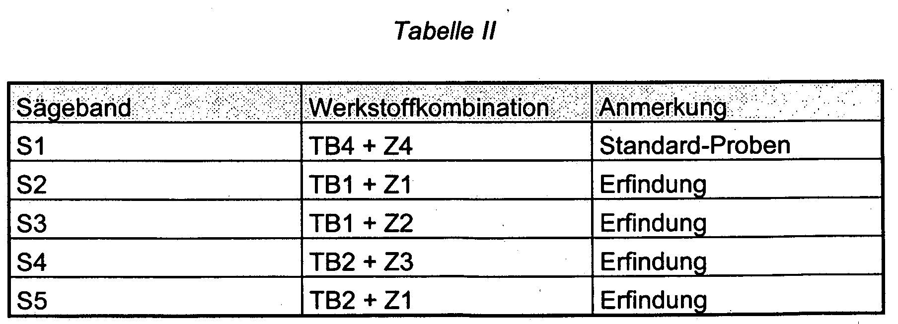
In der nachfolgenden Tabelle I sind zwei erfindungsgemäße Trägerbandwerkstoffe
TB1 und TB2 sowie zwei herkömmliche Trägerbandwerkstoffe
TB3 und TB4 sowie vier Sägezahnwerkstoffe Z1 bis Z4 aus Hochgeschwindigkeitsstahl
zusammengestellt.

Die nachfolgende Tabelle II gibt die Werkstoffkombinationen für fünf Sägebänder
S1 bis S5 wieder, von denen Proben im Hinblick auf ihre Gefügestabilität
und Biegewechselfestigkeit untersucht wurden.
Bei den Versuchen zur Prüfung der Gefügestabilität des Trägerbandwerkstoffs
wurden Proben der Sägebänder S1 bis S5 mit Hilfe des Prüfgeräts
gemäß Fig. 1 untersucht. Dieses Gerät besteht aus einem Bett 1 für einen
Pendeltisch 2, der mit Hilfe eines Kurbelantriebs aus einer angetriebenen
Scheibe 3 und einer Pleuelstange 4 in Abhängigkeit von der Drehzahl der
Scheibe 3 hin- und herbewegt wird. Die zu untersuchende Probe 5 ist zwischen
dem Schlitten 2 und einer Hartmetallrolle 6 eingespannt, die in einem
U-förmigen Bügel 7 drehbar gelagert ist. Die veränderliche Anpreßkraft F
wird über einen Dorn 8 in den Bügel eingeleitet.In the tests to check the structural stability of the carrier tape material
were samples of saw bands S1 to S5 with the help of the test device
examined according to FIG. 1. This device consists of a
Die Probe 5 ist auf zeichnerisch nicht dargestellte Art und Weise gegen jede
Bewegung im Verhältnis zu dem Pendeltisch 2 gesichert.The
In Abhängigkeit von der Drehgeschwindigkeit der Antriebsscheibe 3 lassen
sich mit der Prüfvorrichtung unterschiedliche Bandgeschwindigkeiten bei
unterschiedlichem Anpreßdruck bzw. unterschiedlicher dynamischer Beanspruchung
simulieren, da die Geschwindigkeit der Probe in den Umkehr-
bzw. Totpunkten null ist und sich demgemäß hier ein stets gleicher Geschwindigkeitsabfall
und Geschwindigkeitsanstieg ergibt.Leave depending on the speed of rotation of the
Für die (statische) Belastung F der Rolle 6 wurde der Faktor K der Stribeckschen
Wälzpressung entsprechend der Formel K = F / (Dxleff) verwendet (G.
Niemann, Maschinenelemente, Band I, Seiten 258/260; Springer Verlag
1975). Die Stribecksche Wälzpressung trägt der spezifischen Beanspruchung
der der linienförmigen wälzenden Berührung Anpressrolle/Sägebandrücken
Rechnung.For the (static) load F of the
An den einzelnen Proben ließen sich für insgesamt vier Laststufen bei einer Bewegungsgeschwindigkeit der Proben von 20 m/min durch Anätzen die Breite der Randzone aus Reibmartensit bei den erfindungsgemäßen Trägerbandwerkstoffen TB1 und TB2 im Vergleich mit den beiden herkömmlichen Trägerbandwerkstoffen TB3 und TB4 darstellen. Das Diagramm der Fig. 2 zeigt deutlich, daß die Breite der Reibmartensitzone in Abhängigkeit von der Stribeckschen Pressung bei den erfindungsgemäßen Proben TB1 und TB2 wesentlich geringer ist als bei den Vergleichsproben TB3 und TB4.On the individual samples, a total of four load levels were possible Movement speed of the samples of 20 m / min by etching the Width of the edge zone made of friction martensite in the carrier tape materials according to the invention TB1 and TB2 compared to the two conventional ones Represent carrier tape materials TB3 and TB4. 2 shows clearly that the width of the Reibmartensitzone depending on the Stribeck pressure in the samples TB1 and TB2 according to the invention is significantly lower than for the comparison samples TB3 and TB4.
Zur Bestimmung der Biegewechselfestigkeit wurden Blechstreifen der Abmessung 8 x 1,35 x 80 mm sowie 20 x 1,5 x 80 mm bei einer Temperatur von 1180 °C unter Schutzgas austenitisierend geglüht und abgeschreckt sowie anschließend dreimal bei 560 °C angelassen.Sheet metal strips of the dimension were used to determine the fatigue strength 8 x 1.35 x 80 mm and 20 x 1.5 x 80 mm at one temperature from 1180 ° C under protective gas, annealed and quenched as well as then tempered three times at 560 ° C.
Die Proben wurden sodann einer Schwingprüfung in einer weggesteuerten Federnprüfmaschine (Bauart Bosch-Federschwinge) Drei-Punkt-Biegeschwell-Versuchen einer Prüfspannung von 583 N/mm2 unterworfen.The samples were then subjected to a vibration test in a path-controlled spring testing machine (Bosch spring swing arm type) three-point bending threshold tests with a test voltage of 583 N / mm 2 .
Die wesentlichen Bestandteile der Federschwinge sind ein Schwingbalken, der am einen Ende in einem Festlager gehalten und am anderen Ende von einem verstellbaren Doppelexzenter angetrieben wird, und zwei über Handräder parallel höhenverstellbaren Traversen (Grundplatten) einer oberen und einer unteren Prüfetage. Die Hubhöhe des Exzenters läßt sich in Stufen von 1,5 mm einstellen zwischen 0 und 36 mm, die Hubamplitude nimmt linear von 0 (Festlager) bis auf den Höchstwert am Exzenter zu. Auf der unteren und der oberen Prüfetage befinden sich jeweils bis zu sechs Proben-Aufnahmen mit je 16 Probenplätzen nebeneinander.The main components of the spring rocker are a swing beam, who is held in a fixed camp at one end and at the other end by an adjustable double eccentric is driven, and two via handwheels parallel height-adjustable crossbeams (base plates) of an upper one and a lower test floor. The lifting height of the eccentric can be adjusted in steps of 1.5 mm, set between 0 and 36 mm, the stroke amplitude is linear from 0 (fixed bearing) to the maximum value at the eccentric. On the lower one and the upper test floor each have up to six sample shots with 16 sample places next to each other.
Die Prüflinge werden an beiden Enden lose in die Aufnahmen eingelegt und bilden auf zwei Lagerstellen frei aufliegende Biegeträger der freien Länge L. Die Krafteinteilung zur Erzeugung eines entsprechenden Biegemomentes geschah durch eine mittige Durchbiegung, wozu über jeder einzelnen Probe ein Kontaktstück aus Hartmetall angeordnet und genau mittig positioniert war.The test specimens are loosely inserted into the receptacles at both ends and form free-standing flexible beams of free length L on two bearing points The force distribution to generate a corresponding bending moment was done by a central deflection, for which purpose over each individual sample a contact piece made of hard metal and positioned exactly in the middle was.
Alle Proben einer Lage (Etage) wurden mit Hilfe einer gemeinsamen Kontakt-Leiste durchgebogen. Jede der insgesamt 12 Kontaktleisten war mit 16 Hartmetall-Einzelkontakten versehen. Außerdem waren die Kontakte isoliert auf ihren Leisten angeordnet, so daß jede Probe mit ihrem berührenden Kontakt einen eigenen Stromkreis bildet. Beim Bruch einer Probe wurde dieser Stromkreis unterbrochen und so über eine Verkabelung an einen Mikroprozessor gemeldet, der dem jeweiligen Prüfplatz die aktuelle Schwingzahl als Bruchschwingzahl zuordnete. All samples of one layer (floor) were made using a common contact bar flexed. Each of the 12 contact strips was 16 Provide hard metal individual contacts. The contacts were also isolated arranged on their ledges so that each specimen with their touching Contact forms its own circuit. When a sample broke, it became Circuit interrupted and so via a wiring to a microprocessor reported the current vibration number to the respective test station assigned as a fractional vibration number.
Die Prüfspannung wurde nach einer bekannten Formel aus der gemessenen Durchbiegung und den Bandabmessungen für ein E-Modul von 206.000 N/mm2 berechnet.The test stress was calculated according to a known formula from the measured deflection and the band dimensions for an elastic modulus of 206,000 N / mm 2 .
Das Diagramm der Fig. 3 gibt die Zahl der jeweiligen Lastwechsel in Abhängigkeit vom Verhältnis der Gehalte an Wolfram und Molybdän im Bereich von etwa 0,6 bis etwa 1,5 wieder. Dabei zeigt sich deutlich ein Maximum bei einem Verhältnis von 1,0.The diagram of FIG. 3 shows the number of the respective load changes in dependence on the ratio of the contents of tungsten and molybdenum in the area from about 0.6 to about 1.5 again. A maximum is clearly shown a ratio of 1.0.
Bei Sägeversuchen mit Rohren der Werkstoffnummer 1.4112 wurde die Standzeit eines herkömmlichen Sägebandes S1 (Standardprobe) bei einer Anfangsschnittleistung von 20 cm2/min mit 100% angesetzt und ergab sich bei dem erfindungsgemäßen Sägeband S2 eine Standzeit von 280%. Bei einem weiteren Versuch mit dem Sägeband S2 wurde der Anpreßdruck des Sägebandes so weit erhöht, daß sich eine Anfangsschnittleistung von 35 cm2/min ergab. Die Standzeit betrug bei diesem Versuch 230%. Weitere Versuche mit den Sägebändern S3 ergaben bei einer Anfangsschnittleistung von 35 cm2/min eine Standzeit von 340% und bei dem Sägeband S4 eine Standzeit von 345%, während das erfindungsgemäße Sägeband S5 bei einer Anfangsgeschwindigkeit von 35 cm2/min eine Standzeit von 295% erreichte. Hingegen betrug die Standzeit des herkömmlichen Sägebandes S1 bei der vorerwähnten Anfangsschnittleistung nur 58%. Dies ist auf das Entstehen von Reibmartensit und dadurch verursachte Ermüdungsbrüche im Bandrücken zurückzuführen.In sawing tests with pipes of material number 1.4112, the service life of a conventional saw band S1 (standard sample) was set at 100% with an initial cutting performance of 20 cm 2 / min and the service life of the saw band S2 according to the invention was 280%. In a further test with the saw band S2, the contact pressure of the saw band was increased to such an extent that an initial cutting performance of 35 cm 2 / min resulted. The tool life in this test was 230%. Further tests with the saw bands S3 resulted in a service life of 340% with an initial cutting performance of 35 cm 2 / min and a service life of 345% with the saw band S4, while the saw band S5 according to the invention achieved a service life of 295 at an initial speed of 35 cm 2 / min % reached. In contrast, the service life of the conventional saw band S1 was only 58% with the aforementioned initial cutting performance. This is due to the occurrence of friction martensite and the resulting fatigue fractures in the back of the belt.
Die Versuche zeigen insgesamt die hohe Randzonenbeständigkeit des erfindungsgemäßen Sägebandes bei dynamischer Beanspruchung auch im Falle hoher Schnittleistungen.Overall, the tests show the high marginal zone resistance of the invention Saw band with dynamic stress also in In case of high cutting performance.
Claims (7)
Applications Claiming Priority (2)
| Application Number | Priority Date | Filing Date | Title |
|---|---|---|---|
| DE2002105403 DE10205403B4 (en) | 2002-02-09 | 2002-02-09 | Bimetal bandsaw |
| DE10205403 | 2002-02-09 |
Publications (2)
| Publication Number | Publication Date |
|---|---|
| EP1340830A1 true EP1340830A1 (en) | 2003-09-03 |
| EP1340830B1 EP1340830B1 (en) | 2005-01-26 |
Family
ID=27634835
Family Applications (1)
| Application Number | Title | Priority Date | Filing Date |
|---|---|---|---|
| EP03002794A Expired - Fee Related EP1340830B1 (en) | 2002-02-09 | 2003-02-07 | Bimetallic saw band |
Country Status (5)
| Country | Link |
|---|---|
| US (1) | US6869692B2 (en) |
| EP (1) | EP1340830B1 (en) |
| AR (1) | AR038675A1 (en) |
| AT (1) | ATE287973T1 (en) |
| DE (1) | DE10205403B4 (en) |
Cited By (1)
| Publication number | Priority date | Publication date | Assignee | Title |
|---|---|---|---|---|
| EP1437190A2 (en) * | 2002-12-12 | 2004-07-14 | Stahlwerk Ergste Westig GmbH | Use of a chrome steel alloy |
Families Citing this family (8)
| Publication number | Priority date | Publication date | Assignee | Title |
|---|---|---|---|---|
| FI116044B (en) * | 2002-05-28 | 2005-09-15 | Metso Paper Inc | Bed for cutting a paper or cardboard path in the longitudinal direction |
| CN100374609C (en) * | 2006-01-25 | 2008-03-12 | 周向儒 | Novel chrome steel high speed steel and heat treatment process thereof |
| US20100011594A1 (en) * | 2008-07-15 | 2010-01-21 | Wysk Mark J | Composite Saw Blades |
| AT507956B1 (en) * | 2009-02-16 | 2011-01-15 | Boehler Edelstahl Gmbh & Co Kg | BIMETALLSÄGE |
| CN104451421B (en) * | 2013-09-13 | 2017-01-11 | 宝钢特钢有限公司 | High-strength high-toughness bimetallic strip saw blade back steel and preparation method thereof |
| BR102016001063B1 (en) | 2016-01-18 | 2021-06-08 | Amsted Maxion Fundição E Equipamentos Ferroviários S/A | alloy steel for railway components, and process for obtaining a steel alloy for railway components |
| CN106424941A (en) * | 2016-11-23 | 2017-02-22 | 江苏爱利德科技有限公司 | High-strength toughness bimetallic saw and manufacturing technology thereof |
| PL236222B1 (en) * | 2018-04-11 | 2020-12-28 | Klepuszewska Grazyna Qsgs Tech | Steel intended for monolithic and bimetallic wood cutting band saws |
Citations (6)
| Publication number | Priority date | Publication date | Assignee | Title |
|---|---|---|---|---|
| JPS5837156A (en) * | 1981-08-31 | 1983-03-04 | Daido Steel Co Ltd | Body material |
| JPH0259211A (en) * | 1988-08-20 | 1990-02-28 | Hitachi Koki Co Ltd | Saw blade for power tool and manufacture thereof |
| EP0452526A1 (en) * | 1988-10-21 | 1991-10-23 | Hitachi Metals, Ltd. | High fatigue strength metal band saw backing material |
| EP0569349A1 (en) * | 1992-05-06 | 1993-11-10 | BÖHLER YBBSTALWERKE Ges.m.b.H. | Blank of bimetallic strip and hacksaw blade, made from it |
| EP0566560B1 (en) * | 1992-04-08 | 1996-01-10 | BÖHLER YBBSTALWERKE Ges.m.b.H. | Material for the cutting edge of bi-metal saw blades |
| DE20002593U1 (en) * | 1999-02-15 | 2000-08-17 | Boehler Ybbstal Band Ges M B H | Primary material for saw bands or saw blades |
Family Cites Families (9)
| Publication number | Priority date | Publication date | Assignee | Title |
|---|---|---|---|---|
| JPS528918A (en) * | 1975-07-11 | 1977-01-24 | Hitachi Metals Ltd | Metal band saw body with high fatigue strength |
| JPS637351A (en) * | 1986-06-27 | 1988-01-13 | Daido Steel Co Ltd | Body material for metal band saw |
| AT391826B (en) * | 1987-12-04 | 1990-12-10 | Boehler Gmbh | BI-METAL STRIP FOR METAL SAWS |
| AT396560B (en) * | 1992-05-06 | 1993-10-25 | Boehler Ybbstalwerke | METAL SAW BLADE WITH HIGH FLEXIBILITY AND HIGH CUTTING PERFORMANCE |
| US5863358A (en) * | 1993-12-09 | 1999-01-26 | Uddeholm Strip Steel Aktiebolag | Steel alloy saw blade backing strip |
| US5417777A (en) * | 1994-02-22 | 1995-05-23 | American Saw & Mfg. Company | Alloy for backing steel of a bimetallic band saw blade |
| JP4144094B2 (en) * | 1999-01-28 | 2008-09-03 | 日立金属株式会社 | Blade material for metal band saw |
| DE29914569U1 (en) * | 1999-08-19 | 1999-12-23 | Bender Dieter | Jigsaw blade |
| DE10202770B4 (en) * | 2002-01-25 | 2006-06-14 | Stahlwerk Ergste Westig Gmbh | Bimetal bandsaw |
-
2002
- 2002-02-09 DE DE2002105403 patent/DE10205403B4/en not_active Expired - Fee Related
-
2003
- 2003-02-03 AR ARP030100331 patent/AR038675A1/en active IP Right Grant
- 2003-02-06 US US10/360,199 patent/US6869692B2/en not_active Expired - Fee Related
- 2003-02-07 AT AT03002794T patent/ATE287973T1/en active
- 2003-02-07 EP EP03002794A patent/EP1340830B1/en not_active Expired - Fee Related
Patent Citations (6)
| Publication number | Priority date | Publication date | Assignee | Title |
|---|---|---|---|---|
| JPS5837156A (en) * | 1981-08-31 | 1983-03-04 | Daido Steel Co Ltd | Body material |
| JPH0259211A (en) * | 1988-08-20 | 1990-02-28 | Hitachi Koki Co Ltd | Saw blade for power tool and manufacture thereof |
| EP0452526A1 (en) * | 1988-10-21 | 1991-10-23 | Hitachi Metals, Ltd. | High fatigue strength metal band saw backing material |
| EP0566560B1 (en) * | 1992-04-08 | 1996-01-10 | BÖHLER YBBSTALWERKE Ges.m.b.H. | Material for the cutting edge of bi-metal saw blades |
| EP0569349A1 (en) * | 1992-05-06 | 1993-11-10 | BÖHLER YBBSTALWERKE Ges.m.b.H. | Blank of bimetallic strip and hacksaw blade, made from it |
| DE20002593U1 (en) * | 1999-02-15 | 2000-08-17 | Boehler Ybbstal Band Ges M B H | Primary material for saw bands or saw blades |
Non-Patent Citations (2)
| Title |
|---|
| PATENT ABSTRACTS OF JAPAN vol. 007, no. 118 (C - 167) 21 May 1983 (1983-05-21) * |
| PATENT ABSTRACTS OF JAPAN vol. 014, no. 231 (M - 0974) 16 May 1990 (1990-05-16) * |
Cited By (2)
| Publication number | Priority date | Publication date | Assignee | Title |
|---|---|---|---|---|
| EP1437190A2 (en) * | 2002-12-12 | 2004-07-14 | Stahlwerk Ergste Westig GmbH | Use of a chrome steel alloy |
| EP1437190A3 (en) * | 2002-12-12 | 2007-07-25 | Stahlwerk Ergste Westig GmbH | Use of a chrome steel alloy |
Also Published As
| Publication number | Publication date |
|---|---|
| ATE287973T1 (en) | 2005-02-15 |
| EP1340830B1 (en) | 2005-01-26 |
| US20030152477A1 (en) | 2003-08-14 |
| US6869692B2 (en) | 2005-03-22 |
| DE10205403A1 (en) | 2003-09-04 |
| AR038675A1 (en) | 2005-01-26 |
| DE10205403B4 (en) | 2007-03-29 |
Similar Documents
| Publication | Publication Date | Title |
|---|---|---|
| EP0319511B1 (en) | Bimetallic strip for metal saw blades | |
| DE2732572C2 (en) | Powder mixture for the production of sintered bodies | |
| DE602005003979T2 (en) | Steel band for an exchange blade and its manufacture | |
| EP1331056B1 (en) | Bi-metal band saw blade | |
| DE2722972C2 (en) | High-speed steel containing nitrogen produced using the powder metallurgy process | |
| EP1035942B1 (en) | Method for producing saw bands | |
| DE3041565C2 (en) | ||
| EP2662168A1 (en) | Saw blade including a cutting element made by powder metallurgy | |
| EP0835331B1 (en) | Base material for producing blades for circular saws, cutting-off wheels, mill saws as well as cutting and scraping devices | |
| EP1340830B1 (en) | Bimetallic saw band | |
| EP3976302B1 (en) | Cutting member for a chainsaw and method of manufacturing the same | |
| EP1249511A1 (en) | High speed steel with good high temperature strength manufactured by powder metallurgy | |
| AT402482B (en) | PUNCHING KNIFE FOR PUNCHING TOOLS WITH CURVED CUT | |
| DE19505955B4 (en) | Stainless steel strip of high strength and toughness and method of making the same | |
| DE112008003146T5 (en) | Induction hardening steel having excellent cold workability, rolling member formed of such a steel, and motion guide apparatus using such a rolling member | |
| EP0640693A1 (en) | Paper knife and method of manufacturing | |
| DE102005013538A1 (en) | Plate-shaped element for a belt in a belt type continuously variable transmission | |
| DE4232115C2 (en) | Use of an austenitic steel as a heavy-duty fastener | |
| DE2923532B1 (en) | Use of a ferritic stainless steel for objects resistant in the welded state without post-treatment against intergranular corrosion | |
| DE1927428C2 (en) | Use of a steel band made of a steel with sufficiently good carbide dissolving power for the production of saw blades. - | |
| EP0060577B2 (en) | Turbine blade material with high fatigue-corrosion resistance, method of production and use | |
| DE2412350C2 (en) | Steel for making cutting tools | |
| AT500728B1 (en) | Cutting tool, especially wood chipper blade, comprises an iron alloy containing defined amounts of carbon, silicon, manganese, sulfur, chromium, molybdenum, nickel, vanadium, tungsten and aluminum | |
| DE2014854A1 (en) | Chainsaw unit | |
| DE2251894A1 (en) | Steel for roller components - with 15-80 volume % quasi-carbide dispersed in martensite matrix of surface layer |
Legal Events
| Date | Code | Title | Description |
|---|---|---|---|
| PUAI | Public reference made under article 153(3) epc to a published international application that has entered the european phase |
Free format text: ORIGINAL CODE: 0009012 |
|
| AK | Designated contracting states |
Kind code of ref document: A1 Designated state(s): AT BE BG CH CY CZ DE DK EE ES FI FR GB GR HU IE IT LI LU MC NL PT SE SI SK TR |
|
| AX | Request for extension of the european patent |
Extension state: AL LT LV MK RO |
|
| 17P | Request for examination filed |
Effective date: 20040227 |
|
| GRAP | Despatch of communication of intention to grant a patent |
Free format text: ORIGINAL CODE: EPIDOSNIGR1 |
|
| AKX | Designation fees paid |
Designated state(s): AT GB SE |
|
| REG | Reference to a national code |
Ref country code: DE Ref legal event code: 8566 |
|
| GRAS | Grant fee paid |
Free format text: ORIGINAL CODE: EPIDOSNIGR3 |
|
| GRAA | (expected) grant |
Free format text: ORIGINAL CODE: 0009210 |
|
| AK | Designated contracting states |
Kind code of ref document: B1 Designated state(s): AT GB SE |
|
| REG | Reference to a national code |
Ref country code: GB Ref legal event code: FG4D Free format text: NOT ENGLISH |
|
| REG | Reference to a national code |
Ref country code: IE Ref legal event code: FG4D Free format text: GERMAN |
|
| REG | Reference to a national code |
Ref country code: SE Ref legal event code: TRGR |
|
| GBT | Gb: translation of ep patent filed (gb section 77(6)(a)/1977) |
Effective date: 20050420 |
|
| PLBE | No opposition filed within time limit |
Free format text: ORIGINAL CODE: 0009261 |
|
| STAA | Information on the status of an ep patent application or granted ep patent |
Free format text: STATUS: NO OPPOSITION FILED WITHIN TIME LIMIT |
|
| 26N | No opposition filed |
Effective date: 20051027 |
|
| PGFP | Annual fee paid to national office [announced via postgrant information from national office to epo] |
Ref country code: SE Payment date: 20160222 Year of fee payment: 14 Ref country code: AT Payment date: 20160218 Year of fee payment: 14 Ref country code: GB Payment date: 20160222 Year of fee payment: 14 |
|
| REG | Reference to a national code |
Ref country code: SE Ref legal event code: EUG |
|
| REG | Reference to a national code |
Ref country code: AT Ref legal event code: MM01 Ref document number: 287973 Country of ref document: AT Kind code of ref document: T Effective date: 20170207 |
|
| GBPC | Gb: european patent ceased through non-payment of renewal fee |
Effective date: 20170207 |
|
| PG25 | Lapsed in a contracting state [announced via postgrant information from national office to epo] |
Ref country code: AT Free format text: LAPSE BECAUSE OF NON-PAYMENT OF DUE FEES Effective date: 20170207 |
|
| PG25 | Lapsed in a contracting state [announced via postgrant information from national office to epo] |
Ref country code: SE Free format text: LAPSE BECAUSE OF NON-PAYMENT OF DUE FEES Effective date: 20170208 |
|
| PG25 | Lapsed in a contracting state [announced via postgrant information from national office to epo] |
Ref country code: GB Free format text: LAPSE BECAUSE OF NON-PAYMENT OF DUE FEES Effective date: 20170207 |