EP1336070B1 - Collecteur de phase liquide du milieu de travail d'un systeme de climatisation - Google Patents
Collecteur de phase liquide du milieu de travail d'un systeme de climatisation Download PDFInfo
- Publication number
- EP1336070B1 EP1336070B1 EP01997668A EP01997668A EP1336070B1 EP 1336070 B1 EP1336070 B1 EP 1336070B1 EP 01997668 A EP01997668 A EP 01997668A EP 01997668 A EP01997668 A EP 01997668A EP 1336070 B1 EP1336070 B1 EP 1336070B1
- Authority
- EP
- European Patent Office
- Prior art keywords
- container
- collector
- liquid phase
- pipe
- working medium
- Prior art date
- Legal status (The legal status is an assumption and is not a legal conclusion. Google has not performed a legal analysis and makes no representation as to the accuracy of the status listed.)
- Expired - Lifetime
Links
Images

Classifications
-
- F—MECHANICAL ENGINEERING; LIGHTING; HEATING; WEAPONS; BLASTING
- F25—REFRIGERATION OR COOLING; COMBINED HEATING AND REFRIGERATION SYSTEMS; HEAT PUMP SYSTEMS; MANUFACTURE OR STORAGE OF ICE; LIQUEFACTION SOLIDIFICATION OF GASES
- F25B—REFRIGERATION MACHINES, PLANTS OR SYSTEMS; COMBINED HEATING AND REFRIGERATION SYSTEMS; HEAT PUMP SYSTEMS
- F25B43/00—Arrangements for separating or purifying gases or liquids; Arrangements for vaporising the residuum of liquid refrigerant, e.g. by heat
- F25B43/006—Accumulators
-
- B—PERFORMING OPERATIONS; TRANSPORTING
- B01—PHYSICAL OR CHEMICAL PROCESSES OR APPARATUS IN GENERAL
- B01D—SEPARATION
- B01D45/00—Separating dispersed particles from gases or vapours by gravity, inertia, or centrifugal forces
- B01D45/12—Separating dispersed particles from gases or vapours by gravity, inertia, or centrifugal forces by centrifugal forces
-
- B—PERFORMING OPERATIONS; TRANSPORTING
- B04—CENTRIFUGAL APPARATUS OR MACHINES FOR CARRYING-OUT PHYSICAL OR CHEMICAL PROCESSES
- B04C—APPARATUS USING FREE VORTEX FLOW, e.g. CYCLONES
- B04C9/00—Combinations with other devices, e.g. fans, expansion chambers, diffusors, water locks
-
- F—MECHANICAL ENGINEERING; LIGHTING; HEATING; WEAPONS; BLASTING
- F25—REFRIGERATION OR COOLING; COMBINED HEATING AND REFRIGERATION SYSTEMS; HEAT PUMP SYSTEMS; MANUFACTURE OR STORAGE OF ICE; LIQUEFACTION SOLIDIFICATION OF GASES
- F25B—REFRIGERATION MACHINES, PLANTS OR SYSTEMS; COMBINED HEATING AND REFRIGERATION SYSTEMS; HEAT PUMP SYSTEMS
- F25B13/00—Compression machines, plants or systems, with reversible cycle
-
- B—PERFORMING OPERATIONS; TRANSPORTING
- B04—CENTRIFUGAL APPARATUS OR MACHINES FOR CARRYING-OUT PHYSICAL OR CHEMICAL PROCESSES
- B04C—APPARATUS USING FREE VORTEX FLOW, e.g. CYCLONES
- B04C9/00—Combinations with other devices, e.g. fans, expansion chambers, diffusors, water locks
- B04C2009/002—Combinations with other devices, e.g. fans, expansion chambers, diffusors, water locks with external filters
-
- F—MECHANICAL ENGINEERING; LIGHTING; HEATING; WEAPONS; BLASTING
- F25—REFRIGERATION OR COOLING; COMBINED HEATING AND REFRIGERATION SYSTEMS; HEAT PUMP SYSTEMS; MANUFACTURE OR STORAGE OF ICE; LIQUEFACTION SOLIDIFICATION OF GASES
- F25B—REFRIGERATION MACHINES, PLANTS OR SYSTEMS; COMBINED HEATING AND REFRIGERATION SYSTEMS; HEAT PUMP SYSTEMS
- F25B2400/00—Component parts or details not otherwise provided for in this subclass
- F25B2400/02—Centrifugal separation of gas, liquid or oil
-
- F—MECHANICAL ENGINEERING; LIGHTING; HEATING; WEAPONS; BLASTING
- F25—REFRIGERATION OR COOLING; COMBINED HEATING AND REFRIGERATION SYSTEMS; HEAT PUMP SYSTEMS; MANUFACTURE OR STORAGE OF ICE; LIQUEFACTION SOLIDIFICATION OF GASES
- F25B—REFRIGERATION MACHINES, PLANTS OR SYSTEMS; COMBINED HEATING AND REFRIGERATION SYSTEMS; HEAT PUMP SYSTEMS
- F25B31/00—Compressor arrangements
- F25B31/002—Lubrication
- F25B31/004—Lubrication oil recirculating arrangements
-
- F—MECHANICAL ENGINEERING; LIGHTING; HEATING; WEAPONS; BLASTING
- F25—REFRIGERATION OR COOLING; COMBINED HEATING AND REFRIGERATION SYSTEMS; HEAT PUMP SYSTEMS; MANUFACTURE OR STORAGE OF ICE; LIQUEFACTION SOLIDIFICATION OF GASES
- F25B—REFRIGERATION MACHINES, PLANTS OR SYSTEMS; COMBINED HEATING AND REFRIGERATION SYSTEMS; HEAT PUMP SYSTEMS
- F25B43/00—Arrangements for separating or purifying gases or liquids; Arrangements for vaporising the residuum of liquid refrigerant, e.g. by heat
- F25B43/02—Arrangements for separating or purifying gases or liquids; Arrangements for vaporising the residuum of liquid refrigerant, e.g. by heat for separating lubricants from the refrigerant
Definitions
- the invention relates to a collector for the liquid Phase of the working medium of an air conditioner, with a first and second, for involvement in the cycle the air conditioning provided connecting pieces and with one connected to the second connection piece Guide tube, which led through the interior of the container is, so that part of the draft tube through the Floor area of intended for the vertical arrangement Container runs and its open end in the upper Area of the container is located, which by the Floor area extending part of the draft tube at least has an opening for the return of collected oil and liquid phase of the working medium in the through the Air conditioning circulating working medium has.
- a collector of this type is known from DE 19842019 A1.
- This collector has the disadvantage that he is for a Air conditioning with optional heat pump operation is not is suitable by being at the then required reversal the flow direction, a return of collected oil prevented in the circulation of the air conditioning. This results This is due to the fact that from the guide tube into the container escaping medium its oil content in the container again separates before it is absorbed by the outlet can. The thus possible enrichment of oil in the collector brings with it the danger that the compressor of the air conditioner due to lack of oil.
- a centrifugal separator for a Chiller known with a multipart, vertical oriented case, in which from top to bottom first a cylindrical, then a conical separating space and finally a liquid collecting space are arranged.
- the cylindrical separating space opens tangentially Entry port and in the direction of the vertical axis Immersion tube, which merges into a suction channel. It a cleaning of refrigerant, by a deposition of liquid and particles along one certain flow path. A reversal of the flow direction is neither intended nor possible.
- the invention is based on the object, a collector to find a discharge of oil from the liquid Phase also in the reverse direction of the container flow guaranteed and the one also improved separation effect for the separation of the liquid Phase of the medium has.
- a device having the features of claim 1.
- a device having the features of claim 1.
- For the deposition of the liquid phase is a cyclone-like Separator with a cyclone chamber and with a central drainage spigot forming an overflow is provided in the one of the connecting pieces tangentially opens, with the open end of the guide tube with Distance equiaxial ends before this outlet, so that in reverse flow through the collector of the second Connecting piece via the guide tube to the cyclone chamber liquid phase and oil over the hole and the tangential Connecting piece can be driven out of the collector.
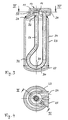
- the collector 1 for the liquid phase 2 of the working medium An air conditioner has an elongated, cylindrical, for the vertical arrangement, preferably in the engine compartment of a Vehicle, provided container 3, on which a first and second connection piece 4, 5 are provided for the Integration of the collector 1 in the cycle of a Air conditioning.
- a first and second connection piece 4, 5 are provided for the Integration of the collector 1 in the cycle of a Air conditioning.
- Through the container 3 extends with a the second connecting piece 5 connected guide tube 6, the passes through the bottom portion 7 of the container 3 and in upper portion 8 of the container 3 ends open.
- the extending through the bottom portion 7 of the container 3 Part of the guide tube 6 has at least one suction opening. 9 for oil, which is in this container area 7 below the liquid phase of the medium of the air conditioning settles. Has, so that it circulates in the through the air conditioning Returned working medium
- a cyclone-like separator 10 For the deposition of the liquid phase from the through Connecting piece 4 inflowing medium is at the top Area 8 of the container 3 a cyclone-like separator 10 provided.
- This has a cyclone chamber 11, in which the connecting piece 4 opens tangentially, so that the medium along the inner surface 12 of the cyclone chamber 11th circulated and separated by centrifugal force liquid phase in the lower part of the cyclone chamber 11th accumulates before moving along the inner surface 13 of a central, an overflow 14 forming Abnningstutzens 15 to the interior of the container 3, together with a small one Proportion of oil drains off.
- the gaseous phase of Medium passes from the cyclone chamber 11 in the Outlet 15 and flows from this into the low Distance 16 adjoining, central draft tube 6.
- the said Distance 16 allows the drainage of the liquid phase from the cyclone chamber 11 along the container wall 17 in the Container 3 in, from the in the same direction centrally in the guide tube 6 outgoing gaseous phase away.
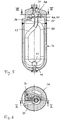
- FIGS. 1 and 2 on the one hand and the 3 and 4 or 5 and 6 on the other hand differ, apart from different types of manufacture according to different connection of the cyclone-type separator 10 with the container 3, essentially through the Arrangement of the connecting pieces 4, 5 on the one hand at the top and lower portion 7,8 of the container 3 and on the other hand together at the top of the container 8.
- both connecting pieces 24,25 at the top 28 of the container 23 requires a different shape of the guide tube 26, at least one Ansaugaugö réelle 29 having Part 30 thereof through the lower portion 27 des To lead container 23.
- the guide tube 26 has a hairpin-shaped redirector 31 to make it up with his Mouth 32 at a small distance from the drain port 33rd continue to lead. Consequently, even with such an arrangement of Connecting piece 24, 25 on hand of the embodiment Guaranteed operation described in FIG.
- the upper, arched area 8 of the container 3 with the drain port 15 to a cylindrical part of the wall of the container. 3 welded and the cyclone-like separator 10 is by bolts 20 at the upper portion 8 of the container. 3 attached flange.
- the guide tube 43 To the directly connected to the guide tube 43 connecting piece 36, without rectangular deflection according to the embodiment according to Fig. 3, next to the other connecting piece 35 to be able to lead laterally out of the collector, the guide tube 43 has a loop-shaped course, with a Crossover in the upper area 37 of the collector.
- the hole 44th having part of the guide tube 43 with a sleeve-like Filter part 45 provided in the lower area around the guide tube 43 is laid around.
- the hole 44 is good in terms of Accessibility arranged at the bottom of the guide tube.
- an absorbent Be arranged dry substance can within the Collector in a manner not shown an absorbent Be arranged dry substance.
Landscapes
- Engineering & Computer Science (AREA)
- Physics & Mathematics (AREA)
- Mechanical Engineering (AREA)
- Thermal Sciences (AREA)
- General Engineering & Computer Science (AREA)
- Chemical & Material Sciences (AREA)
- Analytical Chemistry (AREA)
- Power Engineering (AREA)
- Chemical Kinetics & Catalysis (AREA)
- Cyclones (AREA)
Abstract
Claims (8)
- Collecteur pour la phase liquide d'un milieu ou agent de travail d'une installation de climatisation, comprenant,caractérisé en ce queun premier embout de raccordement (4, 24) prévu pour l'intégration dans le circuit de l'installation de climatisation,un second embout de raccordement (5, 25), etun tube de guidage (6, 26) raccordé au second embout de raccordement (5, 25), qui mène à travers la chambre intérieure du récipient (3, 23) de façon telle, qu'une partie du tube de guidage (6, 26) s'étende à travers une zone de fond inférieure (7, 27) du récipient (3, 23), et qu'une extrémité ouverte (18, 32) se trouve dans une zone supérieure (8, 28) du récipient (3, 23),la partie du tube de guidage (6, 26), qui s'étend à travers la zone de fond (7, 27) possédant au moins une ouverture (9), pour le recyclage dans le milieu de travail circulant à travers l'installation de climatisation, d'huile collectée et de phase liquide du milieu de travail,pour séparer la phase liquide, il est prévu un dispositif séparateur (10) avec une chambre de cyclone (11) et avec un embout d'écoulement (15, 33) formant un trop plein (14), le premier embout de raccordement (4, 24) débouchant tangentiellement dans ledit dispositif séparateur, et l'extrémité ouverte (18, 32) du tube de guidage (6, 26) se terminant dans la zone supérieure (8, 28) du récipient (3, 23), à faible distance de l'embout d'écoulement (15, 33).
- Collecteur selon la revendication 1, caractérisé en ce que le dispositif séparateur (10) du type à cyclone est agencé de manière centrale à l'extrémité supérieure d'un récipient cylindrique (3, 23), et la paroi intérieure (17) du récipient réalise vers le haut, en forme de goulot de bouteille, l'embout d'écoulement (15, 33).
- Collecteur selon la revendication 1 ou 2, caractérisé en ce que les deux embouts de raccordement (4, 5) sont prévus à l'extrémité supérieure et inférieure du récipient (3), et le tube de guidage (6) menant à travers une partie du récipient (3) du collecteur (1) s'étend de manière centrale et non courbée en direction du dispositif séparateur (10) pour la séparation de la phase liquide.
- Collecteur selon la revendication 1, caractérisé en ce que les deux embouts de raccordement (24, 25) sont prévus sur le côté de tête ou le dessus du récipient (23), de sorte que le tube de guidage (26) mène à travers le récipient (23) en débutant par le côté de tête, et présente dans la zone du fond (27), une déviation ou un renvoi (31) au niveau duquel est prévue l'ouverture (29) pour le recyclage dans le milieu de travail, de phase liquide et d'huile collectée.
- Collecteur selon l'une des revendications 1 à 4, caractérisé en ce que l'extrémité ouverte (18, 32) du tube de guidage (6, 26) se termine devant l'embout d'écoulement (15, 33), à une distance (16) qui correspond à la moitié du diamètre du tube de guidage (6, 26).
- Collecteur selon la revendication 5, caractérisé en ce que le tube de guidage (43) présente un tracé en forme de boucle avec un croisement à chevauchement dans la zone supérieure (37) du collecteur.
- Collecteur selon la revendication 4 ou 6, caractérisé en ce que la zone supérieure (37) du collecteur, qui présente la chambre de cyclone (38), est réalisée sous forme de pièce moulée ou forgée (37) en forme de cloche, qui est reliée à une paroi cylindrique (39) formant le récipient (46) du collecteur.
- Collecteur selon la revendication 7, caractérisé en ce que la partie intérieure du dispositif séparateur (42) formant l'embout d'écoulement (40), est insérée et fixée, sous forme de pièce en tôle emboutie (41), dans la pièce moulée ou forgée (37) en forme de cloche
Applications Claiming Priority (3)
| Application Number | Priority Date | Filing Date | Title |
|---|---|---|---|
| DE10058513A DE10058513A1 (de) | 2000-11-24 | 2000-11-24 | Sammler |
| DE10058513 | 2000-11-24 | ||
| PCT/EP2001/013510 WO2002042697A1 (fr) | 2000-11-24 | 2001-11-21 | Collecteur de phase liquide du milieu de travail d'un systeme de climatisation |
Publications (2)
| Publication Number | Publication Date |
|---|---|
| EP1336070A1 EP1336070A1 (fr) | 2003-08-20 |
| EP1336070B1 true EP1336070B1 (fr) | 2005-06-08 |
Family
ID=7664605
Family Applications (1)
| Application Number | Title | Priority Date | Filing Date |
|---|---|---|---|
| EP01997668A Expired - Lifetime EP1336070B1 (fr) | 2000-11-24 | 2001-11-21 | Collecteur de phase liquide du milieu de travail d'un systeme de climatisation |
Country Status (5)
| Country | Link |
|---|---|
| US (1) | US6792773B2 (fr) |
| EP (1) | EP1336070B1 (fr) |
| JP (1) | JP3891429B2 (fr) |
| DE (2) | DE10058513A1 (fr) |
| WO (1) | WO2002042697A1 (fr) |
Families Citing this family (11)
| Publication number | Priority date | Publication date | Assignee | Title |
|---|---|---|---|---|
| US7287399B2 (en) * | 2004-02-17 | 2007-10-30 | Obrist Engineering Gmbh | Collector for the liquid phase of the working medium of an air-conditioning system |
| EP1705437A1 (fr) | 2005-03-23 | 2006-09-27 | Luk Fahrzeug-Hydraulik GmbH & Co. KG | Procédé de lubrification pour le compresseur d'un climatiseur |
| US20060236716A1 (en) * | 2005-04-21 | 2006-10-26 | Griffin Gary E | Refrigerant accumulator |
| CN101398240B (zh) * | 2007-09-29 | 2011-01-19 | 浙江三花制冷集团有限公司 | 一种回油装置和气液分离器 |
| FR2942306B1 (fr) * | 2009-02-18 | 2012-07-13 | Valeo Systemes Thermiques | Accumulateur et circuit de climatisation associe |
| CN103245143B (zh) * | 2012-02-14 | 2016-09-21 | 浙江三花股份有限公司 | 气液分离器 |
| JP6364152B2 (ja) * | 2012-10-30 | 2018-07-25 | 株式会社不二工機 | アキュムレータ |
| DE102014113793A1 (de) | 2014-02-07 | 2015-08-13 | Halla Visteon Climate Control Corporation | Kältemittelakkumulator, insbesondere für Kraftfahrzeugkältemittelkreisläufe |
| US9586164B2 (en) * | 2014-08-05 | 2017-03-07 | Caterpillar Inc. | Particulate separator |
| CN109280617A (zh) * | 2016-08-10 | 2019-01-29 | 天津中天精科科技有限公司 | 一种垃圾处理站的无害化发酵处理系统 |
| DE102024117900A1 (de) * | 2024-06-25 | 2026-01-08 | Mahle International Gmbh | Speicherbehältnis zum Zwischenspeichern von Kältemittel in einem Kältemittelkreislauf |
Family Cites Families (13)
| Publication number | Priority date | Publication date | Assignee | Title |
|---|---|---|---|---|
| US3411319A (en) * | 1966-08-01 | 1968-11-19 | Chrysler Corp | Accumulator |
| US3877904A (en) * | 1974-06-18 | 1975-04-15 | Combustion Eng | Gas-liquid separator |
| DE2650935C3 (de) * | 1976-11-08 | 1981-10-15 | Danfoss A/S, 6430 Nordborg | Kältemaschine mit gekapseltem Motorverdichter |
| US4506523A (en) * | 1982-11-19 | 1985-03-26 | Hussmann Corporation | Oil separator unit |
| US5282370A (en) * | 1992-05-07 | 1994-02-01 | Fayette Tubular Technology Corporation | Air-conditioning system accumulator and method of making same |
| DE4219096C2 (de) * | 1992-06-11 | 1994-06-09 | Karl Friedrich Vedder | Zyklon zur Phasentrennung eines Arbeitsmittels im Teilprozeß der Kondensatentspannung mit hohem Dampfüberschuß |
| JPH0744237U (ja) * | 1992-07-22 | 1995-11-07 | 三星電子株式会社 | 冷暖房兼用空気調和機のアキュムレータ構造 |
| US5551255A (en) * | 1994-09-27 | 1996-09-03 | The United States Of America As Represented By The Secretary Of Commerce | Accumulator distillation insert for zeotropic refrigerant mixtures |
| US5850743A (en) * | 1996-11-13 | 1998-12-22 | Tecumseh Products Company | Suction accumulator assembly |
| JPH1114199A (ja) * | 1997-06-24 | 1999-01-22 | Mitsubishi Electric Corp | アキュムレータ |
| JP3365273B2 (ja) | 1997-09-25 | 2003-01-08 | 株式会社デンソー | 冷凍サイクル |
| US6062039A (en) * | 1998-01-07 | 2000-05-16 | Parker-Hannifin Corporation | Universal accumulator for automobile air conditioning systems |
| IT1312193B1 (it) * | 1999-04-20 | 2002-04-09 | Bundy Kmp S R L | Accumulatore disidratatore per circuiti di refrigerazione e suoprocedimento di assiemaggio |
-
2000
- 2000-11-24 DE DE10058513A patent/DE10058513A1/de not_active Withdrawn
-
2001
- 2001-11-21 EP EP01997668A patent/EP1336070B1/fr not_active Expired - Lifetime
- 2001-11-21 US US10/432,552 patent/US6792773B2/en not_active Expired - Fee Related
- 2001-11-21 JP JP2002544593A patent/JP3891429B2/ja not_active Expired - Fee Related
- 2001-11-21 WO PCT/EP2001/013510 patent/WO2002042697A1/fr not_active Ceased
- 2001-11-21 DE DE50106475T patent/DE50106475D1/de not_active Expired - Lifetime
Also Published As
| Publication number | Publication date |
|---|---|
| US20040093894A1 (en) | 2004-05-20 |
| JP3891429B2 (ja) | 2007-03-14 |
| DE10058513A1 (de) | 2002-06-20 |
| WO2002042697A1 (fr) | 2002-05-30 |
| US6792773B2 (en) | 2004-09-21 |
| EP1336070A1 (fr) | 2003-08-20 |
| JP2004522927A (ja) | 2004-07-29 |
| DE50106475D1 (de) | 2005-07-14 |
Similar Documents
| Publication | Publication Date | Title |
|---|---|---|
| DE4314917C2 (de) | Sammler für Klimaanlagen | |
| EP1336070B1 (fr) | Collecteur de phase liquide du milieu de travail d'un systeme de climatisation | |
| DE4245046C5 (de) | Kondensator für eine Klimaanlage eines Fahrzeuges | |
| DE19609687C5 (de) | Wandkühlgerät für einen Schaltsschrank mit einem Lüfter und einem Lamellen-Wärmetauscher | |
| DE10200673A1 (de) | Kraftfahrzeug-Luftfilter | |
| EP0191153A2 (fr) | Séparateur de fluide, en particulier séparateur gaz/liquide | |
| DE2305470A1 (de) | Abscheider | |
| DE102005005187A1 (de) | Kondensator für eine Klimaanlage, insbesondere eines Kraftfahrzeuges | |
| DE2650935B2 (de) | Kältemaschine mit gekapseltem Motorverdichter | |
| EP2305361B1 (fr) | Système de nettoyage de gaz | |
| DE2602582A1 (de) | Fluessigkeitsabscheider mit absaugduese | |
| DE69911342T2 (de) | Kondensator für klimaanlage mit sammler montiert an halterung | |
| DE60034467T2 (de) | Kompakter kaskadenwäscher zur waschung von abgasen | |
| EP2984421A1 (fr) | Collecteur | |
| EP1132696B1 (fr) | Accumulateur pour un appareil de climatisation travaillant selon le principe d' "orifice", en particulier pour un appareil de climatisation de véhicule | |
| EP1035388B1 (fr) | Accumulateur pour un appareil de climatisation travaillant selon le principe d' "orifice", en particulier pour un appareil de climatisation de véhicule | |
| EP1685784A1 (fr) | Dispositif d'aspiration | |
| EP1088508A2 (fr) | Filtre à liquides pour appareil de nettoyage des sols | |
| DE8328892U1 (de) | Schwimmerventil | |
| DE102005009191B3 (de) | Kältemittelsammler mit Filter/Trockner-Einheit | |
| DE10158409C1 (de) | Akkumulator für eine Klimaanlage, insbesondere Fahrzeugklimaanlage | |
| DE19946217C1 (de) | Akkumulator für eine nach dem "Orifice"-Prinzip arbeitende Klimaanlage, insbesondere Fahrzeugklimaanlage | |
| DE2646259C3 (de) | Druckluftreiniger, insbesondere für Bremsanlagen von Kraftfahrzeugen | |
| DE641876C (de) | Vorrichtung zum Abscheiden von fluessigen Bestandteilen aus Gasen | |
| DE3621993C2 (fr) |
Legal Events
| Date | Code | Title | Description |
|---|---|---|---|
| PUAI | Public reference made under article 153(3) epc to a published international application that has entered the european phase |
Free format text: ORIGINAL CODE: 0009012 |
|
| 17P | Request for examination filed |
Effective date: 20030506 |
|
| AK | Designated contracting states |
Designated state(s): AT BE CH CY DE DK ES FI FR GB GR IE IT LI LU MC NL PT SE TR |
|
| RBV | Designated contracting states (corrected) |
Designated state(s): AT BE CH DE FR GB LI |
|
| GRAP | Despatch of communication of intention to grant a patent |
Free format text: ORIGINAL CODE: EPIDOSNIGR1 |
|
| RBV | Designated contracting states (corrected) |
Designated state(s): DE FR GB |
|
| GRAS | Grant fee paid |
Free format text: ORIGINAL CODE: EPIDOSNIGR3 |
|
| GRAA | (expected) grant |
Free format text: ORIGINAL CODE: 0009210 |
|
| AK | Designated contracting states |
Kind code of ref document: B1 Designated state(s): DE FR GB |
|
| REG | Reference to a national code |
Ref country code: GB Ref legal event code: FG4D Free format text: NOT ENGLISH |
|
| REF | Corresponds to: |
Ref document number: 50106475 Country of ref document: DE Date of ref document: 20050714 Kind code of ref document: P |
|
| GBT | Gb: translation of ep patent filed (gb section 77(6)(a)/1977) |
Effective date: 20050902 |
|
| ET | Fr: translation filed | ||
| PLBE | No opposition filed within time limit |
Free format text: ORIGINAL CODE: 0009261 |
|
| STAA | Information on the status of an ep patent application or granted ep patent |
Free format text: STATUS: NO OPPOSITION FILED WITHIN TIME LIMIT |
|
| 26N | No opposition filed |
Effective date: 20060309 |
|
| REG | Reference to a national code |
Ref country code: FR Ref legal event code: CD Ref country code: FR Ref legal event code: CA |
|
| PGFP | Annual fee paid to national office [announced via postgrant information from national office to epo] |
Ref country code: GB Payment date: 20101118 Year of fee payment: 10 |
|
| PGFP | Annual fee paid to national office [announced via postgrant information from national office to epo] |
Ref country code: FR Payment date: 20111214 Year of fee payment: 11 |
|
| PGFP | Annual fee paid to national office [announced via postgrant information from national office to epo] |
Ref country code: DE Payment date: 20120131 Year of fee payment: 11 |
|
| GBPC | Gb: european patent ceased through non-payment of renewal fee |
Effective date: 20121121 |
|
| REG | Reference to a national code |
Ref country code: FR Ref legal event code: ST Effective date: 20130731 |
|
| REG | Reference to a national code |
Ref country code: DE Ref legal event code: R119 Ref document number: 50106475 Country of ref document: DE Effective date: 20130601 |
|
| PG25 | Lapsed in a contracting state [announced via postgrant information from national office to epo] |
Ref country code: DE Free format text: LAPSE BECAUSE OF NON-PAYMENT OF DUE FEES Effective date: 20130601 |
|
| PG25 | Lapsed in a contracting state [announced via postgrant information from national office to epo] |
Ref country code: GB Free format text: LAPSE BECAUSE OF NON-PAYMENT OF DUE FEES Effective date: 20121121 Ref country code: FR Free format text: LAPSE BECAUSE OF NON-PAYMENT OF DUE FEES Effective date: 20121130 |