EP1336070B1 - Collector for the liquid phase of a working medium of an air conditioning system - Google Patents
Collector for the liquid phase of a working medium of an air conditioning system Download PDFInfo
- Publication number
- EP1336070B1 EP1336070B1 EP01997668A EP01997668A EP1336070B1 EP 1336070 B1 EP1336070 B1 EP 1336070B1 EP 01997668 A EP01997668 A EP 01997668A EP 01997668 A EP01997668 A EP 01997668A EP 1336070 B1 EP1336070 B1 EP 1336070B1
- Authority
- EP
- European Patent Office
- Prior art keywords
- container
- collector
- liquid phase
- pipe
- working medium
- Prior art date
- Legal status (The legal status is an assumption and is not a legal conclusion. Google has not performed a legal analysis and makes no representation as to the accuracy of the status listed.)
- Expired - Lifetime
Links
Images

Classifications
-
- F—MECHANICAL ENGINEERING; LIGHTING; HEATING; WEAPONS; BLASTING
- F25—REFRIGERATION OR COOLING; COMBINED HEATING AND REFRIGERATION SYSTEMS; HEAT PUMP SYSTEMS; MANUFACTURE OR STORAGE OF ICE; LIQUEFACTION SOLIDIFICATION OF GASES
- F25B—REFRIGERATION MACHINES, PLANTS OR SYSTEMS; COMBINED HEATING AND REFRIGERATION SYSTEMS; HEAT PUMP SYSTEMS
- F25B43/00—Arrangements for separating or purifying gases or liquids; Arrangements for vaporising the residuum of liquid refrigerant, e.g. by heat
- F25B43/006—Accumulators
-
- B—PERFORMING OPERATIONS; TRANSPORTING
- B01—PHYSICAL OR CHEMICAL PROCESSES OR APPARATUS IN GENERAL
- B01D—SEPARATION
- B01D45/00—Separating dispersed particles from gases or vapours by gravity, inertia, or centrifugal forces
- B01D45/12—Separating dispersed particles from gases or vapours by gravity, inertia, or centrifugal forces by centrifugal forces
-
- B—PERFORMING OPERATIONS; TRANSPORTING
- B04—CENTRIFUGAL APPARATUS OR MACHINES FOR CARRYING-OUT PHYSICAL OR CHEMICAL PROCESSES
- B04C—APPARATUS USING FREE VORTEX FLOW, e.g. CYCLONES
- B04C9/00—Combinations with other devices, e.g. fans, expansion chambers, diffusors, water locks
-
- F—MECHANICAL ENGINEERING; LIGHTING; HEATING; WEAPONS; BLASTING
- F25—REFRIGERATION OR COOLING; COMBINED HEATING AND REFRIGERATION SYSTEMS; HEAT PUMP SYSTEMS; MANUFACTURE OR STORAGE OF ICE; LIQUEFACTION SOLIDIFICATION OF GASES
- F25B—REFRIGERATION MACHINES, PLANTS OR SYSTEMS; COMBINED HEATING AND REFRIGERATION SYSTEMS; HEAT PUMP SYSTEMS
- F25B13/00—Compression machines, plants or systems, with reversible cycle
-
- B—PERFORMING OPERATIONS; TRANSPORTING
- B04—CENTRIFUGAL APPARATUS OR MACHINES FOR CARRYING-OUT PHYSICAL OR CHEMICAL PROCESSES
- B04C—APPARATUS USING FREE VORTEX FLOW, e.g. CYCLONES
- B04C9/00—Combinations with other devices, e.g. fans, expansion chambers, diffusors, water locks
- B04C2009/002—Combinations with other devices, e.g. fans, expansion chambers, diffusors, water locks with external filters
-
- F—MECHANICAL ENGINEERING; LIGHTING; HEATING; WEAPONS; BLASTING
- F25—REFRIGERATION OR COOLING; COMBINED HEATING AND REFRIGERATION SYSTEMS; HEAT PUMP SYSTEMS; MANUFACTURE OR STORAGE OF ICE; LIQUEFACTION SOLIDIFICATION OF GASES
- F25B—REFRIGERATION MACHINES, PLANTS OR SYSTEMS; COMBINED HEATING AND REFRIGERATION SYSTEMS; HEAT PUMP SYSTEMS
- F25B2400/00—Component parts or details not otherwise provided for in this subclass
- F25B2400/02—Centrifugal separation of gas, liquid or oil
-
- F—MECHANICAL ENGINEERING; LIGHTING; HEATING; WEAPONS; BLASTING
- F25—REFRIGERATION OR COOLING; COMBINED HEATING AND REFRIGERATION SYSTEMS; HEAT PUMP SYSTEMS; MANUFACTURE OR STORAGE OF ICE; LIQUEFACTION SOLIDIFICATION OF GASES
- F25B—REFRIGERATION MACHINES, PLANTS OR SYSTEMS; COMBINED HEATING AND REFRIGERATION SYSTEMS; HEAT PUMP SYSTEMS
- F25B31/00—Compressor arrangements
- F25B31/002—Lubrication
- F25B31/004—Lubrication oil recirculating arrangements
-
- F—MECHANICAL ENGINEERING; LIGHTING; HEATING; WEAPONS; BLASTING
- F25—REFRIGERATION OR COOLING; COMBINED HEATING AND REFRIGERATION SYSTEMS; HEAT PUMP SYSTEMS; MANUFACTURE OR STORAGE OF ICE; LIQUEFACTION SOLIDIFICATION OF GASES
- F25B—REFRIGERATION MACHINES, PLANTS OR SYSTEMS; COMBINED HEATING AND REFRIGERATION SYSTEMS; HEAT PUMP SYSTEMS
- F25B43/00—Arrangements for separating or purifying gases or liquids; Arrangements for vaporising the residuum of liquid refrigerant, e.g. by heat
- F25B43/02—Arrangements for separating or purifying gases or liquids; Arrangements for vaporising the residuum of liquid refrigerant, e.g. by heat for separating lubricants from the refrigerant
Definitions
- the invention relates to a collector for the liquid Phase of the working medium of an air conditioner, with a first and second, for involvement in the cycle the air conditioning provided connecting pieces and with one connected to the second connection piece Guide tube, which led through the interior of the container is, so that part of the draft tube through the Floor area of intended for the vertical arrangement Container runs and its open end in the upper Area of the container is located, which by the Floor area extending part of the draft tube at least has an opening for the return of collected oil and liquid phase of the working medium in the through the Air conditioning circulating working medium has.
- a collector of this type is known from DE 19842019 A1.
- This collector has the disadvantage that he is for a Air conditioning with optional heat pump operation is not is suitable by being at the then required reversal the flow direction, a return of collected oil prevented in the circulation of the air conditioning. This results This is due to the fact that from the guide tube into the container escaping medium its oil content in the container again separates before it is absorbed by the outlet can. The thus possible enrichment of oil in the collector brings with it the danger that the compressor of the air conditioner due to lack of oil.
- a centrifugal separator for a Chiller known with a multipart, vertical oriented case, in which from top to bottom first a cylindrical, then a conical separating space and finally a liquid collecting space are arranged.
- the cylindrical separating space opens tangentially Entry port and in the direction of the vertical axis Immersion tube, which merges into a suction channel. It a cleaning of refrigerant, by a deposition of liquid and particles along one certain flow path. A reversal of the flow direction is neither intended nor possible.
- the invention is based on the object, a collector to find a discharge of oil from the liquid Phase also in the reverse direction of the container flow guaranteed and the one also improved separation effect for the separation of the liquid Phase of the medium has.
- a device having the features of claim 1.
- a device having the features of claim 1.
- For the deposition of the liquid phase is a cyclone-like Separator with a cyclone chamber and with a central drainage spigot forming an overflow is provided in the one of the connecting pieces tangentially opens, with the open end of the guide tube with Distance equiaxial ends before this outlet, so that in reverse flow through the collector of the second Connecting piece via the guide tube to the cyclone chamber liquid phase and oil over the hole and the tangential Connecting piece can be driven out of the collector.
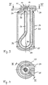
- the collector 1 for the liquid phase 2 of the working medium An air conditioner has an elongated, cylindrical, for the vertical arrangement, preferably in the engine compartment of a Vehicle, provided container 3, on which a first and second connection piece 4, 5 are provided for the Integration of the collector 1 in the cycle of a Air conditioning.
- a first and second connection piece 4, 5 are provided for the Integration of the collector 1 in the cycle of a Air conditioning.
- Through the container 3 extends with a the second connecting piece 5 connected guide tube 6, the passes through the bottom portion 7 of the container 3 and in upper portion 8 of the container 3 ends open.
- the extending through the bottom portion 7 of the container 3 Part of the guide tube 6 has at least one suction opening. 9 for oil, which is in this container area 7 below the liquid phase of the medium of the air conditioning settles. Has, so that it circulates in the through the air conditioning Returned working medium
- a cyclone-like separator 10 For the deposition of the liquid phase from the through Connecting piece 4 inflowing medium is at the top Area 8 of the container 3 a cyclone-like separator 10 provided.
- This has a cyclone chamber 11, in which the connecting piece 4 opens tangentially, so that the medium along the inner surface 12 of the cyclone chamber 11th circulated and separated by centrifugal force liquid phase in the lower part of the cyclone chamber 11th accumulates before moving along the inner surface 13 of a central, an overflow 14 forming Abnningstutzens 15 to the interior of the container 3, together with a small one Proportion of oil drains off.
- the gaseous phase of Medium passes from the cyclone chamber 11 in the Outlet 15 and flows from this into the low Distance 16 adjoining, central draft tube 6.
- the said Distance 16 allows the drainage of the liquid phase from the cyclone chamber 11 along the container wall 17 in the Container 3 in, from the in the same direction centrally in the guide tube 6 outgoing gaseous phase away.
- FIGS. 1 and 2 on the one hand and the 3 and 4 or 5 and 6 on the other hand differ, apart from different types of manufacture according to different connection of the cyclone-type separator 10 with the container 3, essentially through the Arrangement of the connecting pieces 4, 5 on the one hand at the top and lower portion 7,8 of the container 3 and on the other hand together at the top of the container 8.
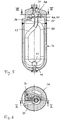
- both connecting pieces 24,25 at the top 28 of the container 23 requires a different shape of the guide tube 26, at least one Ansaugaugö réelle 29 having Part 30 thereof through the lower portion 27 des To lead container 23.
- the guide tube 26 has a hairpin-shaped redirector 31 to make it up with his Mouth 32 at a small distance from the drain port 33rd continue to lead. Consequently, even with such an arrangement of Connecting piece 24, 25 on hand of the embodiment Guaranteed operation described in FIG.
- the upper, arched area 8 of the container 3 with the drain port 15 to a cylindrical part of the wall of the container. 3 welded and the cyclone-like separator 10 is by bolts 20 at the upper portion 8 of the container. 3 attached flange.
- the guide tube 43 To the directly connected to the guide tube 43 connecting piece 36, without rectangular deflection according to the embodiment according to Fig. 3, next to the other connecting piece 35 to be able to lead laterally out of the collector, the guide tube 43 has a loop-shaped course, with a Crossover in the upper area 37 of the collector.
- the hole 44th having part of the guide tube 43 with a sleeve-like Filter part 45 provided in the lower area around the guide tube 43 is laid around.
- the hole 44 is good in terms of Accessibility arranged at the bottom of the guide tube.
- an absorbent Be arranged dry substance can within the Collector in a manner not shown an absorbent Be arranged dry substance.
Landscapes
- Engineering & Computer Science (AREA)
- Physics & Mathematics (AREA)
- Mechanical Engineering (AREA)
- Thermal Sciences (AREA)
- General Engineering & Computer Science (AREA)
- Chemical & Material Sciences (AREA)
- Analytical Chemistry (AREA)
- Power Engineering (AREA)
- Chemical Kinetics & Catalysis (AREA)
- Cyclones (AREA)
Abstract
Description
Die Erfindung betrifft einen Sammler für die flüssige Phase des Arbeitsmediums einer Klimaanlage, mit einem ersten und zweiten, für die Einbindung in den Kreislauf der Klimaanlage vorgesehenen Anschlussstutzen und mit einem an den zweiten Anschlussstutzen angeschlossenen Leitrohr, das durch den Innenraum des Behälters geführt ist, so dass ein Teil des Leitrohres durch den Bodenbereich des für die vertikale Anordnung vorgesehenen Behälters verläuft und sich sein offenes Ende im oberen Bereich des Behälters befindet, wobei der durch den Bodenbereich verlaufende Teil des Leitrohres mindestens eine Öffnung hat, zur Rückführung von gesammeltem Öl und flüssiger Phase des Arbeitsmediums in das durch die Klimaanlage zirkulierende Arbeitsmedium aufweist.The invention relates to a collector for the liquid Phase of the working medium of an air conditioner, with a first and second, for involvement in the cycle the air conditioning provided connecting pieces and with one connected to the second connection piece Guide tube, which led through the interior of the container is, so that part of the draft tube through the Floor area of intended for the vertical arrangement Container runs and its open end in the upper Area of the container is located, which by the Floor area extending part of the draft tube at least has an opening for the return of collected oil and liquid phase of the working medium in the through the Air conditioning circulating working medium has.
Ein Sammler dieser Art ist bekannt durch die DE 19842019 A1. Dieser Sammler hat den Nachteil, dass er für eine Klimaanlage mit wahlweisem Wärmepumpenbetrieb nicht geeignet ist, indem er bei der dann erforderlichen Umkehr der Strömungsrichtung eine Rückführung von gesammeltem Öl in den Kreislauf der Klimaanlage verhindert. Dies ergibt sich dadurch, dass aus dem Leitrohr in den Behälter hinein ausströmendes Medium seinen Ölanteil im Behälter wieder ausscheidet, bevor es vom Abströmstutzen aufgenommen werden kann. Die somit mögliche Anreicherung von Öl im Sammler bringt die Gefahr mit sich, dass der Kompressor der Klimaanlage durch Ölmangel ausfällt.A collector of this type is known from DE 19842019 A1. This collector has the disadvantage that he is for a Air conditioning with optional heat pump operation is not is suitable by being at the then required reversal the flow direction, a return of collected oil prevented in the circulation of the air conditioning. This results This is due to the fact that from the guide tube into the container escaping medium its oil content in the container again separates before it is absorbed by the outlet can. The thus possible enrichment of oil in the collector brings with it the danger that the compressor of the air conditioner due to lack of oil.
Aus der DE 2650935 C3 ist ein Fliehkraftabscheider für eine Kältemaschine bekannt mit einem mehrteiligen, vertikal orientierten Gehäuse, in dem von oben nach unten zunächst ein zylindrischer, dann ein konischer Abscheideraum und schließlich ein Flüssigkeitssammelraum angeordnet sind. In den zylinderischen Abscheideraum münden tangential ein Eintrittsstutzen und in Richtung der vertikalen Achse ein Tauchrohr, welches in einen Sauggaskanal übergeht. Es erfolgt eine Reinigung von Kältemittel, durch ein Abscheiden von Flüssigkeit und Partikeln entlang eines bestimmten Strömungsweges. Eine Umkehrung der Strömungsrichtung ist weder vorgesehen noch möglich.From DE 2650935 C3 is a centrifugal separator for a Chiller known with a multipart, vertical oriented case, in which from top to bottom first a cylindrical, then a conical separating space and finally a liquid collecting space are arranged. In the cylindrical separating space opens tangentially Entry port and in the direction of the vertical axis Immersion tube, which merges into a suction channel. It a cleaning of refrigerant, by a deposition of liquid and particles along one certain flow path. A reversal of the flow direction is neither intended nor possible.
Der Erfindung liegt die Aufgabe zugrunde, einen Sammler zu finden, der einen Austrag von Öl aus der flüssigen Phase auch bei umgekehrter Richtung der Behälterdurchströmung gewährleistet und der ausserdem eine verbesserte Trennwirkung zur Abscheidung der flüssigen Phase des Mediums aufweist.The invention is based on the object, a collector to find a discharge of oil from the liquid Phase also in the reverse direction of the container flow guaranteed and the one also improved separation effect for the separation of the liquid Phase of the medium has.
Die Lösung der genannten Aufgabe erfolgt erfindungsgemäss durch eine Vorrichtung mit den Merkmalen des Anspruchs 1. Zur Abscheidung der flüssigen Phase ist dabei eine zyklonartige Trenneinrichtung mit einer Zyklonkammer und mit einem zentralen, einen Überlauf bildenden Abflussstutzen vorgesehen ist, in die einer der Anschlussstutzen tangential mündet, wobei das offene Ende des Leitrohres mit Abstand gleichachsig vor diesem Abflussstutzen endet, so dass bei umgekehrter Durchströmung des Sammlers vom zweiten Anschlussstutzen über das Leitrohr zur Zyklonkammer flüssige Phase und Öl über das Loch und den tangentialen Anschlussstutzen aus dem Sammler austreibbar ist. The solution of the stated object is achieved according to the invention by a device having the features of claim 1. For the deposition of the liquid phase is a cyclone-like Separator with a cyclone chamber and with a central drainage spigot forming an overflow is provided in the one of the connecting pieces tangentially opens, with the open end of the guide tube with Distance equiaxial ends before this outlet, so that in reverse flow through the collector of the second Connecting piece via the guide tube to the cyclone chamber liquid phase and oil over the hole and the tangential Connecting piece can be driven out of the collector.
Im Folgenden wird die Erfindung an Hand von zwei in den Zeichnungen dargestellten Ausführungsbeispielen näher erläutert. Es zeigt:
- Fig.1
- einen Axialschnitt durch einen Sammler mit ungekrümmtem Leitrohr,
- Fig.2
- einen Radialschnitt entlang der Linie II-II der Fig. 1,
- Fig.3
- einen Axialschnitt durch einen Sammler mit gekrümmtem Leitrohr entlang der Linie III-III der Fig. 4,
- Fig.4
- einen Radialschnitt entlang der Linie IV-IV der Fig. 3,
- Fig.5
- einen Axialschnitt durch einen Sammler entsprechend einem dritten Ausführungsbeispiel der Erfindung und
- Fig.6
- einen Radialschnitt durch den Sammler nach Fig. 5.
- Fig.1
- an axial section through a collector with non-curved guide tube,
- Fig.2
- a radial section along the line II-II of Fig. 1,
- Figure 3
- an axial section through a collector with a curved guide tube along the line III-III of Fig. 4,
- Figure 4
- a radial section along the line IV-IV of Fig. 3,
- Figure 5
- an axial section through a collector according to a third embodiment of the invention and
- Figure 6
- a radial section through the collector of Fig. 5th
Der Sammler 1 für die flüssige Phase 2 des Arbeitsmediums
einer Klimaanlage hat einen länglichen, zylindrischen, für
die vertikale Anordnung, vorzugsweise im Motorraum eines
Fahrzeuges, vorgesehenen Behälter 3, an dem ein erster und
zweiter Anschlussstutzen 4, 5 vorgesehen sind, für die
Einbindung des Sammlers 1 in den Kreislauf einer
Klimaanlage. Durch den Behälter 3 erstreckt sich ein mit
dem zweiten Anschlussstutzen 5 verbundenes Leitrohr 6, das
durch den Bodenbereich 7 des Behälters 3 verläuft und im
oberen Bereich 8 des Behälters 3 offen endet.The collector 1 for the
Der durch den Bodenbereich 7 des Behälters 3 verlaufende
Teil des Leitrohres 6 hat mindestens eine Ansaugöffnung 9
für Öl, das sich in diesem Behälterbereich 7 unterhalb der
flüssigen Phase des Mediums der Klimaanlage absetzt. hat,
so dass es in das durch die Klimaanlage zirkulierende
Arbeitsmedium zurückgelangtThe extending through the
Für die Abscheidung der flüssigen Phase aus dem durch den
Anschlussstutzen 4 zuströmenden Medium ist am oberen
Bereich 8 des Behälters 3 eine zyklonartige Trenneinrichtung
10 vorgesehen. Diese hat eine Zyklonkammer 11,
in die der Anschlussstutzen 4 tangential einmündet, so dass
das Medium entlang der Innenfläche 12 der Zyklonkammer 11
zirkuliert und die durch Zentrifugalkraft sich abscheidende
flüssige Phase im unteren Teil der Zyklonkammer 11
ansammelt, bevor es entlang der Innenfläche 13 eines
zentralen, einen Überlauf 14 bildenden Abflussstutzens 15
zum Innenraum des Behälters 3, zusammen mit einem geringen
Anteil an Öl abfliesst. Auch die gasförmige Phase des
Mediums gelangt aus der Zyklonkammer 11 in den
Abflussstutzen 15 und strömt von diesem in das mit geringem
Abstand 16 angrenzende, zentrale Leitrohr 6. Der genannte
Abstand 16 ermöglicht das Abfliessen der flüssigen Phase
aus der Zyklonkammer 11 entlang der Behälterwand 17 in den
Behälter 3 hinein, von der in gleicher Richtung zentral in
das Leitrohr 6 abströmenden gasförmigen Phase weg.For the deposition of the liquid phase from the through
Connecting
Die gleichachsig vor dem Abflussstutzen 15 in geringem Abstand
16 endende Anordnung der Mündung 18 des Leitrohres und der
beschriebene konstruktive Aufbau der zyklonartigen
Trenneinrichtung 10 gewährleisten, dass auch bei Durchströmung
des Sammlers 1 in umgekehrter Richtung, d.h. in Richtung vom
zweiten Anschlussstutzen 5 zum ersten Anschlussstutzen 4, ein
Austrag von flüssiger Phase 2 und von Öl aus dem Sammler 1
erfolgt. Dabei wird die flüssige Phase 2 und/oder Öl, aufgrund
des bei der Durchströmung durch das Leitrohr 6 entstehenden
Unterdrucks, durch das Loch 9 angesaugt und in die zyklonartige
Trenneinrichtung 10 eingeführt. Dort trifft es auf die
als Prallfläche wirkende, obere Wand 19 der Zyklonkammer 11
und wird von dort aus gegen ihre periphere Fläche 12 gedrückt,
um von dieser über den tangentialen Anschlussstutzen 4 in den
Kreislauf der Klimaanlage abzuströmen.The equiaxial in front of the
Die Ausführungsbeispiele der Fig. 1 und 2 einerseits und der
Fig.3 und 4 bzw. 5 und 6 andererseits unterscheiden sich,
abgesehen von unterschiedlicher Art der herstellungsgemäss
unterschiedlichen Verbindung der zyklonartigen Trenneinrichtung
10 mit dem Behälter 3, im wesentlichen durch die
Anordnung der Anschlussstutzen 4, 5 einerseits am oberen und
unteren Bereich 7,8 des Behälters 3 und andererseits
gemeinsam am oberen Bereich 8 des Behälters.The embodiments of FIGS. 1 and 2 on the one hand and the
3 and 4 or 5 and 6 on the other hand differ,
apart from different types of manufacture according to
different connection of the cyclone-
Die Anordnung beider Anschlussstutzen 24,25 am oberen Bereich
28 des Behälters 23 bedingt eine andere Form des Leitrohres
26, um einen mindestens eine Ansaugsaugöffnung 29 aufweisenden
Teil 30 desselben durch den unteren Bereich 27des
Behälters 23 zu führen. Hierzu hat das Leitrohr 26 eine
haarnadelförmige Umlenkung 31, um es nach oben mit seiner
Mündung 32 in geringem Abstand von dem Abflussstutzen 33
weiter zu führen. Folglich ist auch bei solcher Anordnung der
Anschlussstutzen 24, 25 die an Hand des Ausführungsbeispieles
nach Fig. 1 beschriebene Funktionsweise gewährleistet.The arrangement of both connecting
Beim Ausführungsbeispiel nach Fig.3 ist der Abflussstutzen
33 im Tiefziehverfahren flaschenhalsförmig aus der Wand 34
des Behälters 23 ausgeformt und die zyklonartige Trennvorrichtung
ist kappenförmig auf den gewölbten oberen
Bereich 28 des Behälters 23 aufgeschweisst. Im Unterschied
hierzu ist beim Ausführungsbeispiel nach Fig. 1 der obere,
gewölbte Bereich 8 des Behälters 3 mit dem Abflussstutzen
15 an einen zylindrischen Teil der Wand des Behälters 3
angeschweisst und die zyklonartige Trennvorrichtung 10 ist
durch Schraubbolzen 20 am oberen Bereich 8 des Behälters 3
flanschartig befestigt. In the embodiment of Figure 3 is the
Das hinsichtlich der Herstellung des Sammlers besonders
vorteilhafte Ausführungsbeispiel nach Fig.5 und 6 unterscheidet
sich von demjenigen nach Fig.3 und 4 im wesentlichen
dadurch, dass der die Anschlussstutzen 35 und 36 aufweisende
obere Bereich des Sammlers einschliesslich der Zyklonkammer 38
als glockenförmiges Guss- oder Schmiedeteil 37 ausgeführt ist,
das mit der zylindrischen Wand 39 beispielsweise durch
Schweissen verbunden ist. Der den Abflussstutzen 40 bildende
Innenteil der zyklonartigen Trenneinrichtung 42 ist als tiefgezogenes
Blechteil 41 in das glockenförmige Guss- oder
Schmiedeteil 37 eingesetzt und befestigt.This is especially true with regard to the manufacture of the collector
advantageous embodiment of Figure 5 and 6 differs
from that of Fig.3 and 4 substantially
in that the connecting
Um den mit dem Leitrohr 43 direkt verbundenen Anschlussstutzen
36, ohne rechtwinkelige Umlenkung entsprechend dem Ausführungsbeispiel
nach Fig. 3, neben dem anderen Anschlussstutzen
35 seitlich aus dem Sammler herausführen zu können,
hat das Leitrohr 43 einen schlaufenförmigen Verlauf, mit einer
Überkreuzung im oberen Bereich 37 des Sammlers.To the directly connected to the
Zur Abfiltrierung von Verunreinigungen ist der das Loch 44
aufweisende Teil des Leitrohres 43 mit einem hülsenartigen
Filterteil 45 versehen, das im unteren Bereich um das Leitrohr
43 herumgelegt ist. Das Loch 44 ist im Hinblick auf eine gute
Zugänglichkeit an der Unterseite des Leitrohres angeordnet.
Zur Zurückhaltung von Feuchtigkeit, kann innerhalb des
Sammlers in nicht dargestellter Weise eine absorbierende
Trockensubstanz angeordnet sein.For filtering off impurities is the hole 44th
having part of the
Claims (8)
- Collector for the liquid phase of the working medium of an air-conditioning unit, with:characterised in thata first connection tube (4, 24) provided for connection to the circuit of the air-conditioning unit,a second connection tube (5, 25), and witha pipe (6, 26) connected to the said second connection tube (5, 25), which passes through the inside space of a container (3, 23) in such manner that part of the said pipe (2, 26) passes through a lower, bottom area (7, 27) of the container (3, 23) and has an open end (18, 32) in an upper area (8, 28) of the container (3, 23), such thatthe part of the pipe (6, 26) passing through the bottom area (7, 27) of the container is provided with at least one opening (9) for the return of collected oil and liquid phase of the working medium back into the working medium circulating through the air-conditioning unit,to precipitate the liquid phase, a separator (10) with a cyclone chamber (11) and a outlet pipe (15, 33) that forms an overflow weir (14) are provided, into which the first connection tube (4, 24) opens tangentially, such that the open end (18, 32) of the pipe (6, 26) in the upper area (8, 28) of the container (3, 23) ends a small distance away from the outlet pipe (15, 33).
- Collector according to Claim 1, characterised in that the cyclone-like separator (10) is arranged centrally at the upper end of a cylindrical container (3, 23) and the inner wall of the said container narrows upwards in a bottleneck shape to form the outlet pipe (15, 33).
- Collector according to Claims 1 or 2, characterised in that the two connection tubes (4, 5) are provided at the top and bottom ends of the container (3) and the pipe (6) passing through part of the container (3) runs centrally and with no bends towards the separator (10) for precipitating the liquid phase.
- Collector according to Claim 1, characterised in that both of the connection tubes (4, 5) are at the top of the container (23), so that the pipe (26) begins at the top of the container (23), passes down through it, and in its bottom area describes a bend (31) in which the opening (9) for returning liquid phase and collected oil back into the working medium is provided.
- Collector according to any of Claims 1 to 4, characterised in that the open end (18, 32) of the pipe (6, 26) ends a distance (16) away from the outlet pipe (15, 33) that corresponds to half the diameter of the pipe (6, 26).
- Collector according to Claims 4 or 6, characterised in that the pipe (43) has a looped shape with a cross-over in the upper area (37) of the collector.
- Collector according to Claim 7, characterised in that the upper part (37) of the collector containing the cyclone chamber (38) is made as a bell-shaped casting or forged component (37), which is joined to a cylindrical wall (39) forming the container (46) of the collector.
- Collector according to Claim 7, characterised in that the inside portion of the cyclone-like separator (42) that forms the outlet pipe (40) is a deep-drawn sheet component (41) inserted in and fixed to the bell-shaped casting or forged component (37).
Applications Claiming Priority (3)
| Application Number | Priority Date | Filing Date | Title |
|---|---|---|---|
| DE10058513A DE10058513A1 (en) | 2000-11-24 | 2000-11-24 | collector |
| DE10058513 | 2000-11-24 | ||
| PCT/EP2001/013510 WO2002042697A1 (en) | 2000-11-24 | 2001-11-21 | Collector for the liquid phase of a working medium of an air conditioning system |
Publications (2)
| Publication Number | Publication Date |
|---|---|
| EP1336070A1 EP1336070A1 (en) | 2003-08-20 |
| EP1336070B1 true EP1336070B1 (en) | 2005-06-08 |
Family
ID=7664605
Family Applications (1)
| Application Number | Title | Priority Date | Filing Date |
|---|---|---|---|
| EP01997668A Expired - Lifetime EP1336070B1 (en) | 2000-11-24 | 2001-11-21 | Collector for the liquid phase of a working medium of an air conditioning system |
Country Status (5)
| Country | Link |
|---|---|
| US (1) | US6792773B2 (en) |
| EP (1) | EP1336070B1 (en) |
| JP (1) | JP3891429B2 (en) |
| DE (2) | DE10058513A1 (en) |
| WO (1) | WO2002042697A1 (en) |
Families Citing this family (11)
| Publication number | Priority date | Publication date | Assignee | Title |
|---|---|---|---|---|
| US7287399B2 (en) * | 2004-02-17 | 2007-10-30 | Obrist Engineering Gmbh | Collector for the liquid phase of the working medium of an air-conditioning system |
| EP1705437A1 (en) | 2005-03-23 | 2006-09-27 | Luk Fahrzeug-Hydraulik GmbH & Co. KG | Oil supply method for an air conditioner compressor |
| US20060236716A1 (en) * | 2005-04-21 | 2006-10-26 | Griffin Gary E | Refrigerant accumulator |
| CN101398240B (en) * | 2007-09-29 | 2011-01-19 | 浙江三花制冷集团有限公司 | Oil return device and gas-liquid separator |
| FR2942306B1 (en) * | 2009-02-18 | 2012-07-13 | Valeo Systemes Thermiques | ACCUMULATOR AND AIR CONDITIONING CIRCUIT |
| CN103245143B (en) * | 2012-02-14 | 2016-09-21 | 浙江三花股份有限公司 | Gas-liquid separator |
| JP6364152B2 (en) * | 2012-10-30 | 2018-07-25 | 株式会社不二工機 | accumulator |
| DE102014113793A1 (en) | 2014-02-07 | 2015-08-13 | Halla Visteon Climate Control Corporation | Refrigerant accumulator, in particular for motor vehicle refrigerant circuits |
| US9586164B2 (en) * | 2014-08-05 | 2017-03-07 | Caterpillar Inc. | Particulate separator |
| CN109280617A (en) * | 2016-08-10 | 2019-01-29 | 天津中天精科科技有限公司 | A kind of innoxious fermentation process system of Biohazard Waste Disposal |
| DE102024117900A1 (en) * | 2024-06-25 | 2026-01-08 | Mahle International Gmbh | Storage container for intermediate storage of refrigerant in a refrigerant circuit |
Family Cites Families (13)
| Publication number | Priority date | Publication date | Assignee | Title |
|---|---|---|---|---|
| US3411319A (en) * | 1966-08-01 | 1968-11-19 | Chrysler Corp | Accumulator |
| US3877904A (en) * | 1974-06-18 | 1975-04-15 | Combustion Eng | Gas-liquid separator |
| DE2650935C3 (en) * | 1976-11-08 | 1981-10-15 | Danfoss A/S, 6430 Nordborg | Refrigeration machine with encapsulated motor compressor |
| US4506523A (en) * | 1982-11-19 | 1985-03-26 | Hussmann Corporation | Oil separator unit |
| US5282370A (en) * | 1992-05-07 | 1994-02-01 | Fayette Tubular Technology Corporation | Air-conditioning system accumulator and method of making same |
| DE4219096C2 (en) * | 1992-06-11 | 1994-06-09 | Karl Friedrich Vedder | Cyclone for phase separation of a working fluid in the partial process of condensate expansion with high excess steam |
| JPH0744237U (en) * | 1992-07-22 | 1995-11-07 | 三星電子株式会社 | Accumulator structure of air conditioner for both air conditioning and heating |
| US5551255A (en) * | 1994-09-27 | 1996-09-03 | The United States Of America As Represented By The Secretary Of Commerce | Accumulator distillation insert for zeotropic refrigerant mixtures |
| US5850743A (en) * | 1996-11-13 | 1998-12-22 | Tecumseh Products Company | Suction accumulator assembly |
| JPH1114199A (en) * | 1997-06-24 | 1999-01-22 | Mitsubishi Electric Corp | accumulator |
| JP3365273B2 (en) | 1997-09-25 | 2003-01-08 | 株式会社デンソー | Refrigeration cycle |
| US6062039A (en) * | 1998-01-07 | 2000-05-16 | Parker-Hannifin Corporation | Universal accumulator for automobile air conditioning systems |
| IT1312193B1 (en) * | 1999-04-20 | 2002-04-09 | Bundy Kmp S R L | DEHYDRATOR ACCUMULATOR FOR REFRIGERATION CIRCUITS AND ASSEMBLY PROCEDURE |
-
2000
- 2000-11-24 DE DE10058513A patent/DE10058513A1/en not_active Withdrawn
-
2001
- 2001-11-21 EP EP01997668A patent/EP1336070B1/en not_active Expired - Lifetime
- 2001-11-21 US US10/432,552 patent/US6792773B2/en not_active Expired - Fee Related
- 2001-11-21 JP JP2002544593A patent/JP3891429B2/en not_active Expired - Fee Related
- 2001-11-21 WO PCT/EP2001/013510 patent/WO2002042697A1/en not_active Ceased
- 2001-11-21 DE DE50106475T patent/DE50106475D1/en not_active Expired - Lifetime
Also Published As
| Publication number | Publication date |
|---|---|
| US20040093894A1 (en) | 2004-05-20 |
| JP3891429B2 (en) | 2007-03-14 |
| DE10058513A1 (en) | 2002-06-20 |
| WO2002042697A1 (en) | 2002-05-30 |
| US6792773B2 (en) | 2004-09-21 |
| EP1336070A1 (en) | 2003-08-20 |
| JP2004522927A (en) | 2004-07-29 |
| DE50106475D1 (en) | 2005-07-14 |
Similar Documents
| Publication | Publication Date | Title |
|---|---|---|
| DE4314917C2 (en) | Air conditioning collectors | |
| EP1336070B1 (en) | Collector for the liquid phase of a working medium of an air conditioning system | |
| DE4245046C5 (en) | Condenser for an air conditioning system of a vehicle | |
| DE19609687C5 (en) | Wall cooling unit for a control cabinet with a fan and a fin heat exchanger | |
| DE10200673A1 (en) | Air filter for motor vehicles has water drain outlet with connected water holder with drain valve, having rubber valve closure part | |
| EP0191153A2 (en) | Fluidseparator, especially gas/liquid separator | |
| DE2305470A1 (en) | SEPARATOR | |
| DE102005005187A1 (en) | Condenser for an air conditioning system, in particular a motor vehicle | |
| DE2650935B2 (en) | Refrigeration machine with encapsulated motor compressor | |
| EP2305361B1 (en) | Gas purification system | |
| DE2602582A1 (en) | Separator to remove liquids from gases - has reentrainment pipe between outlet venturi throat and liquor sump | |
| DE69911342T2 (en) | AIR CONDITIONER CONDENSER WITH COLLECTOR MOUNTED ON BRACKET | |
| DE60034467T2 (en) | COMPACT CASCADE WASHER FOR WASTE WASTE | |
| EP2984421A1 (en) | Receiver | |
| EP1132696B1 (en) | Accumulator for an air conditioner working according to the "orifice" principle, in particular for a vehicle air conditioner | |
| EP1035388B1 (en) | Accumulator for an air conditioner working according to the "orifice" principle, in particular for a vehicle air conditioner | |
| EP1685784A1 (en) | Suction device | |
| EP1088508A2 (en) | Liquid filter for a surface cleaning machine | |
| DE8328892U1 (en) | FLOAT VALVE | |
| DE102005009191B3 (en) | Refrigerant collector with filter / dryer unit | |
| DE10158409C1 (en) | Accumulator, for a vehicle air conditioning unit, has a casing with inlets/outlets for refrigerants and a relatively low flow resistance | |
| DE19946217C1 (en) | Accumulator for orifice principle air-conditioning unit e.g. automobile air-conditioning unit, has drying insert projecting into flow path of refrigerant medium between accumulator housing entry and exit | |
| DE2646259C3 (en) | Compressed air cleaners, in particular for braking systems for motor vehicles | |
| DE641876C (en) | Device for separating liquid components from gases | |
| DE3621993C2 (en) |
Legal Events
| Date | Code | Title | Description |
|---|---|---|---|
| PUAI | Public reference made under article 153(3) epc to a published international application that has entered the european phase |
Free format text: ORIGINAL CODE: 0009012 |
|
| 17P | Request for examination filed |
Effective date: 20030506 |
|
| AK | Designated contracting states |
Designated state(s): AT BE CH CY DE DK ES FI FR GB GR IE IT LI LU MC NL PT SE TR |
|
| RBV | Designated contracting states (corrected) |
Designated state(s): AT BE CH DE FR GB LI |
|
| GRAP | Despatch of communication of intention to grant a patent |
Free format text: ORIGINAL CODE: EPIDOSNIGR1 |
|
| RBV | Designated contracting states (corrected) |
Designated state(s): DE FR GB |
|
| GRAS | Grant fee paid |
Free format text: ORIGINAL CODE: EPIDOSNIGR3 |
|
| GRAA | (expected) grant |
Free format text: ORIGINAL CODE: 0009210 |
|
| AK | Designated contracting states |
Kind code of ref document: B1 Designated state(s): DE FR GB |
|
| REG | Reference to a national code |
Ref country code: GB Ref legal event code: FG4D Free format text: NOT ENGLISH |
|
| REF | Corresponds to: |
Ref document number: 50106475 Country of ref document: DE Date of ref document: 20050714 Kind code of ref document: P |
|
| GBT | Gb: translation of ep patent filed (gb section 77(6)(a)/1977) |
Effective date: 20050902 |
|
| ET | Fr: translation filed | ||
| PLBE | No opposition filed within time limit |
Free format text: ORIGINAL CODE: 0009261 |
|
| STAA | Information on the status of an ep patent application or granted ep patent |
Free format text: STATUS: NO OPPOSITION FILED WITHIN TIME LIMIT |
|
| 26N | No opposition filed |
Effective date: 20060309 |
|
| REG | Reference to a national code |
Ref country code: FR Ref legal event code: CD Ref country code: FR Ref legal event code: CA |
|
| PGFP | Annual fee paid to national office [announced via postgrant information from national office to epo] |
Ref country code: GB Payment date: 20101118 Year of fee payment: 10 |
|
| PGFP | Annual fee paid to national office [announced via postgrant information from national office to epo] |
Ref country code: FR Payment date: 20111214 Year of fee payment: 11 |
|
| PGFP | Annual fee paid to national office [announced via postgrant information from national office to epo] |
Ref country code: DE Payment date: 20120131 Year of fee payment: 11 |
|
| GBPC | Gb: european patent ceased through non-payment of renewal fee |
Effective date: 20121121 |
|
| REG | Reference to a national code |
Ref country code: FR Ref legal event code: ST Effective date: 20130731 |
|
| REG | Reference to a national code |
Ref country code: DE Ref legal event code: R119 Ref document number: 50106475 Country of ref document: DE Effective date: 20130601 |
|
| PG25 | Lapsed in a contracting state [announced via postgrant information from national office to epo] |
Ref country code: DE Free format text: LAPSE BECAUSE OF NON-PAYMENT OF DUE FEES Effective date: 20130601 |
|
| PG25 | Lapsed in a contracting state [announced via postgrant information from national office to epo] |
Ref country code: GB Free format text: LAPSE BECAUSE OF NON-PAYMENT OF DUE FEES Effective date: 20121121 Ref country code: FR Free format text: LAPSE BECAUSE OF NON-PAYMENT OF DUE FEES Effective date: 20121130 |