EP1334782B1 - Stanze - Google Patents
Stanze Download PDFInfo
- Publication number
- EP1334782B1 EP1334782B1 EP01976812A EP01976812A EP1334782B1 EP 1334782 B1 EP1334782 B1 EP 1334782B1 EP 01976812 A EP01976812 A EP 01976812A EP 01976812 A EP01976812 A EP 01976812A EP 1334782 B1 EP1334782 B1 EP 1334782B1
- Authority
- EP
- European Patent Office
- Prior art keywords
- punch
- driver
- retainer collar
- punch driver
- guide
- Prior art date
- Legal status (The legal status is an assumption and is not a legal conclusion. Google has not performed a legal analysis and makes no representation as to the accuracy of the status listed.)
- Expired - Lifetime
Links
Images

Classifications
-
- B—PERFORMING OPERATIONS; TRANSPORTING
- B21—MECHANICAL METAL-WORKING WITHOUT ESSENTIALLY REMOVING MATERIAL; PUNCHING METAL
- B21D—WORKING OR PROCESSING OF SHEET METAL OR METAL TUBES, RODS OR PROFILES WITHOUT ESSENTIALLY REMOVING MATERIAL; PUNCHING METAL
- B21D45/00—Ejecting or stripping-off devices arranged in machines or tools dealt with in this subclass
- B21D45/003—Ejecting or stripping-off devices arranged in machines or tools dealt with in this subclass in punching machines or punching tools
-
- B—PERFORMING OPERATIONS; TRANSPORTING
- B21—MECHANICAL METAL-WORKING WITHOUT ESSENTIALLY REMOVING MATERIAL; PUNCHING METAL
- B21D—WORKING OR PROCESSING OF SHEET METAL OR METAL TUBES, RODS OR PROFILES WITHOUT ESSENTIALLY REMOVING MATERIAL; PUNCHING METAL
- B21D28/00—Shaping by press-cutting; Perforating
- B21D28/02—Punching blanks or articles with or without obtaining scrap; Notching
- B21D28/12—Punching using rotatable carriers
-
- B—PERFORMING OPERATIONS; TRANSPORTING
- B21—MECHANICAL METAL-WORKING WITHOUT ESSENTIALLY REMOVING MATERIAL; PUNCHING METAL
- B21D—WORKING OR PROCESSING OF SHEET METAL OR METAL TUBES, RODS OR PROFILES WITHOUT ESSENTIALLY REMOVING MATERIAL; PUNCHING METAL
- B21D28/00—Shaping by press-cutting; Perforating
- B21D28/24—Perforating, i.e. punching holes
- B21D28/34—Perforating tools; Die holders
-
- Y—GENERAL TAGGING OF NEW TECHNOLOGICAL DEVELOPMENTS; GENERAL TAGGING OF CROSS-SECTIONAL TECHNOLOGIES SPANNING OVER SEVERAL SECTIONS OF THE IPC; TECHNICAL SUBJECTS COVERED BY FORMER USPC CROSS-REFERENCE ART COLLECTIONS [XRACs] AND DIGESTS
- Y10—TECHNICAL SUBJECTS COVERED BY FORMER USPC
- Y10T—TECHNICAL SUBJECTS COVERED BY FORMER US CLASSIFICATION
- Y10T83/00—Cutting
- Y10T83/869—Means to drive or to guide tool
- Y10T83/8727—Plural tools selectively engageable with single drive
- Y10T83/8732—Turret of tools
-
- Y—GENERAL TAGGING OF NEW TECHNOLOGICAL DEVELOPMENTS; GENERAL TAGGING OF CROSS-SECTIONAL TECHNOLOGIES SPANNING OVER SEVERAL SECTIONS OF THE IPC; TECHNICAL SUBJECTS COVERED BY FORMER USPC CROSS-REFERENCE ART COLLECTIONS [XRACs] AND DIGESTS
- Y10—TECHNICAL SUBJECTS COVERED BY FORMER USPC
- Y10T—TECHNICAL SUBJECTS COVERED BY FORMER US CLASSIFICATION
- Y10T83/00—Cutting
- Y10T83/929—Tool or tool with support
- Y10T83/9411—Cutting couple type
- Y10T83/9423—Punching tool
- Y10T83/9428—Shear-type male tool
-
- Y—GENERAL TAGGING OF NEW TECHNOLOGICAL DEVELOPMENTS; GENERAL TAGGING OF CROSS-SECTIONAL TECHNOLOGIES SPANNING OVER SEVERAL SECTIONS OF THE IPC; TECHNICAL SUBJECTS COVERED BY FORMER USPC CROSS-REFERENCE ART COLLECTIONS [XRACs] AND DIGESTS
- Y10—TECHNICAL SUBJECTS COVERED BY FORMER USPC
- Y10T—TECHNICAL SUBJECTS COVERED BY FORMER US CLASSIFICATION
- Y10T83/00—Cutting
- Y10T83/929—Tool or tool with support
- Y10T83/9457—Joint or connection
- Y10T83/9473—For rectilinearly reciprocating tool
- Y10T83/9476—Tool is single element with continuous cutting edge [e.g., punch, etc.]
Definitions
- the present invention relates to a die device which is attached to a suitable punch press such as a turret punch press so as to be used. More specifically, the invention relates to the die device, which is configured to have a punch body with a punch blade portion on its lower end is equipped with a punch guide so as to freely move up and down, and a disc-shaped stripper blade encircling the punch blade portion is detachably provided on a lower end of the punch guide and in which attachment/detachment and fixing of the stripper plate are easy and secure and height adjustment after repolishing of the punch blade portion is easy.
- a prior example of the present invention includes Japanese Patent Application Laid-Open No. 10-113725 (1998 ) (prior example 1) and Japanese Patent Application Laid-Open No. 2000-288656 (prior example 2).
- a punch body having a punch blade portion on its lower end is provided in a cylindrical punch guide so as to be movable up and down, an oscillation locking piece having a latch portion being freely engaged with an engagement groove formed on an outer peripheral surface of a stripper plate on its lower end is provided on a lower end of the punch guide so as to freely oscillate to an inside-outside direction and be energized to an outside direction, and a turning ring, which has a locking piece pressuring portion for pressuring the oscillation locking piece to an inside direction so that the latch portion of the oscillation locking piece is engaged with the engagement groove of the stripper plate, is turnably provided to the lower end of the punch guide.
- the stripper plate can be attached to and detached from the lower end of the punch guide comparatively easily, the oscillation locking piece is made of a plate spring and it is occasionally broken at the attachment portion to the punch guide.
- the configuration is such that the turning ring is energized to a turning direction by a coil spring so that the latch portion of the oscillation locking piece is maintained to be engaged with the engagement groove of the stripper plate, a further improvement is desired in relation to that the turning ring occasionally turns against an energizing force of the coil spring due to vibration or the like at the time of a punching workpiece.
- a stopper ring is elastically mounted between a ring member fixed to an upper end of a punch driver fitted to an upper portion of the punch guide so as to be movable only up and down and an upper surface of the punch guide, a punch head member having a punch head on its upper end is fitted into the punch driver rotatively, and an external thread portion provided to an upper portion of the punch body is screwed into an internal thread portion provided to the punch head member so that an up-down position is adjustable.
- the present invention is devised in order to solve the above problems, and its first object is to provide a die device in which the height adjustment after the repolishing of the punch blade portion is easy.
- JP-A-06000551 discloses a die device comprising a retainer collar being provided on an upper portion of a punch guide wherein a lower punch driver connected to a punch body is being fitted and supported into the punch guide so as to freely move up and down; an upper punch driver inserted into the retainer collar so as to freely move up and down in a projecting manner; wherein in the above configuration, the upper punch driver and an upper portion of the lower punch driver are screwed into each other in an up-down adjustable manner.
- the present invention provides a die device as defined in claim 1.
- the punch driver piercing through the retainer collar movably up and down is rotated with respect to the punch guide.
- the upper punch driver since the upper punch driver is screwed into the lower punch driver and rotates with respect to the lower punch provided on the punch guide movably up and down, the upper punch driver moves up and down with respect to the lower punch driver.
- an engagement concave portion is provided in a vicinity of an outer peripheral portion of the retainer collar in a peripheral direction; and a latch member, which is maintained so as to be freely engaged with and disengaged from the engagement concave portion and normally in a engages state, is provided on the upper portion of the punch guide ii a diametrical direction so as to freely move.
- the latch member which is provided on the upper portion of the punch guide movably to the center in the diametrical direction, is engaged with the engagement concave portion provided in the vicinity of the outer peripheral portion of the retainer collar in the peripheral direction, so that the retainer collar cannot rotate with respect to the punch guide.
- the latch member is moved to the inside in the diametrical direction so as to be disengaged from the engagement portion of the retainer collar, the retainer collar is enabled to rotate with respect to the punch guide.
- the latch portion which is provided on the upper portion of the punch guide movable to the center in the diametrical direction, is engaged with the engagement concave portion provided in the vicinity of the outer peripheral portion of the retainer collar in the peripheral direction, so that the retainer collar is disabled to rotate with respect to the punch guide.
- the latch member is moved to the inside in the diametrical direction so as to be disengaged from the engagement concave portion of the retainer collar, so that the retainer collar is enabled to rotate with respect to the punch guide. For this reason, when the retainer collar is rotated relatively with respect to the punch guide, the up-down positional relationship between the upper punch driver and the lower punch driver is easily adjusted so that the punch height can be adjusted.
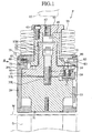
- Fig. 1 is a sectional view showing a punch die P as the die device in accordance with the present invention.
- the punch die P can be mounted to an upper turret such as a turret punch press, and a punch body 33 having a punch blade portion 31 on its lower end is provided into a punch guide 29 so as to be movable up and down, and a lower punch driver 37 is mounted integrally to an upper side of the punch body 33 by a connecting bolt 35 in a normal state.
- a key 39 is mounted to a vicinity of a boundary between the punch body 33 and the lower punch driver 37 by bolts 41, and the punch body 33 and the lower punch driver 37 are supported integrally to the punch guide 29 so as not to rotate and be movable up and down.
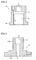
- the lower punch driver 37 has a convex portion 37H, which is provided with a thread portion 43 on its outer peripheral surface, on an upper side of a disc-shaped lower portion 37L.
- An upper portion of the convex portion 37H is provided with a hole 45 into which a head portion 35H of the connecting bolt 35 is fitted, and the convex portion 37H and the lower portion 37L are provided with an inner diameter through hole 47 through which an underhead 35L of the connecting bolt 35 is put.
- a cylindrical upper punch driver 49 is provided so as to cover an outside of the convex portion 37H.
- An inside of the upper punch driver 49 has a tool hole 51 for inserting a tool for rotating the connecting bolt 35 thereinto, and a space 55 provided with a thread portion 53 on its inner peripheral surface for screwing the convex portion 37H.
- an outer peripheral surf ace of the upper punch driver 49 is provided with a key groove 57 in an up-down direction.
- a lower end of the upper punch driver 49 has a flange portion 59 protruding outward.
- the upper punch driver 49 is relatively rotated with respect to the lower punch driver 37, so that an up-down position of the upper punch driver 49 with respect to the lower punch driver 37 can be adjusted by functions of the thread portions 43 and 53.
- the lower portion 37L of the lower punch driver 37 is supported to an upper end of the punch guide 29 by a retaining portion 61 protruding inward so as to be incapable of ascending and capable of descending.
- each supporting pins 96 are provided to an outside of the upper end of the punch guide 29 so as to protrude.
- Elastic means such as a coil spring is provided between an upper surface of an upper turret of the turret punch press and the supporting pins 96, and the punch die P of the present invention is always energized upward.
- a punch head 65 is mounted to an upper end surface of the upper punch driver 49 by a connecting bolt 63.
- a center of the punch head 65 is provided with a tool inserting hole 67 for rotating the connecting bolt 35.
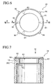
- the punch guide 29 shown in Figs. 6 and 7 is in a state before assembly of the punch die P of the present invention.
- An upper end 29U of the punch guide 29 is formed with a horizontal hole 94 which extends to a horizontal direction.
- the horizontal hole 94 is opened to an outer surface of the punch guide 29.
- the other end of the horizontal hole 94 does not pierce an inside surface of the retaining portion 61 and is hollow just before the inside surface of the retaining portion 61.
- an approximately center portion of the horizontal hole 94 is formed with another vertical hole 75 which extends to a vertical direction.
- the horizontal hole 94 and the vertical hole 75 are connected with each other.
- the vertical hole 75 has an opening 95 on an upper end of the vertical hole 75 so that it upper end is opened to an upper surface of the retaining portion 61.
- the horizontal hole 94 is provided with a push button 69 which is movable to a diametrical direction (a left-right direction in Fig. 1 ).
- the push button 69 is pressured to be energized to an outer direction by an elastic member 71 such as a coil spring.
- the push button 69 is provided with a stopper pin 73 as a latch member which pierces the push button 69 up and down in a fitted state.
- the stopper pin 73 can move to a direction R of the horizontal direction (the left-right direction in Fig. 1 ) inside the vertical hole 75. Further, an upper end of the stopper pin 73 pierces the opening 95 provided to the upper end of the vertical hole 75 upward and protrudes upward from the opening 95. The stopper pin 73 can move to the direction R inside the vertical hole 75, but since it abuts against an outside wall of the vertical hole 75 so as not to slip out of the vertical hole 75.
- Arc shaped convex portions 80 are provided on a lower surface of the retainer collar 77 so as to protrude with equal gaps.
- the ten convex portions 80 are formed.
- engagement concave portions 81 are provided between the convex portions 80.
- a peripheral groove 79 is provided inside the convex portions 80 on the lower surface of the retainer collar 77.
- the peripheral groove 79 is formed on the lower surface of the retainer collar 77, and its peripheral portion is provided with the ten engagement concave portions 81.
- the engagement concave portions 81 and the peripheral groove 79 are formed, as a result the arc shaped convex portions 80 are formed to protrude on the lower surface of the retainer collar 77 with the equal gaps.
- the upper end of the stopper pin 73 is provided so as to be engaged with the peripheral groove 79 formed on the lower surface of the retainer collar 77 and a plurality of the engagement concave portions 81 formed on a peripheral direction of the outside of the peripheral groove 79 with a predetermined pitch alternatively.
- the push button 69 is pushed down to the outer direction by the function of the elastic member 71 so that the upper end of the stopper pin 73 is engaged with the engagement concave portion 81, and a fixed state is obtained in such a manner that rotation of the retainer collar 77 with respect to the punch guide 29 is inihibited.
- the retaining portion 61 of the punch guide 29 is provided with three tapped holes 83 which pierce a radial direction with an interval of 120°, and setscrews 85 (see Fig. 1 ), for example, are screwed into the tapped holes 83 , respectively, so that the retaining portion 61 is freely engaged with and disengaged from a retaining groove 87 of the retainer collar 77.
- a through hole 89 which pierces the retainer collar 77 to a diametrical direction is provided (see Figs. 4 and 5 ), and a spring pin 91 (see Fig. 1 ) which always protrudes to a center direction is provided on the through hole 89. Since the spring pin 91 is engaged with a key groove 57 (see Fig. 2 ) provided on the outer peripheral surface of the upper punch driver 49 in the up-down direction, the retainer collar 77 integrally rotates with the upper punch driver 49 and is movable to the up-down direction.
- a stopper spring 93 is provided between the punch head 65 and the retainer collar 77. Due to repulsion of the stopper spring 93, the upper punch driver 49 is energized upward via the punch head 65 so as to be disengaged from the retainer collar 77. However, since the flange portion 59 of the upper punch driver 49 is retained by the retainer collar 77 in an unascendable state, the upper punch driver 49 does not slip off. Namely, the upper punch driver 49 is made to be a unit by a combination of the retainer collar 77, the stripper spring 93, the punch head 65 and the connecting bolt 63. Due to this unit state, as mentioned later, an adjusting operation on punch height of the present invention is easily performed.
- the punch height adjusting operation will be explained. Firstly in a state that the upper end of the stopper pin 73 protrudes upward from the opening 95 so as to be engaged with the engagement concave portion 81 of the retainer collar 77, the push button 69 is pushed to the direction R. When the push button 69 is pushed to the direction R against the energizing force of the elastic member 71, the upper end of the stopper pin 73 is disengaged from the engagement concave portion 81 so as to be located in a position of the inner peripheral groove 79. Namely, as shown in Fig. 5 , the stopper pin 73 is moved to the direction R to be in a position shown as a stopper pin 73'.
- the stopper pin 73 can run to a direction S or a direction T in the peripheral groove 74. Therefore, the punch guide 29 can rotate to the direction S or T.
- the lower punch driver 37 is in a state that it cannot rotate with respect to the punch guide 29 due to the function of the key 39, due to the rotation of the punch guide 29 to the direction S or T, the lower punch driver 37 as well as the punch guide 29 integrally rotates to the same direction.
- the upper punch driver 49 rotates relatively with respect to the lower punch driver 37, and the lower punch driver 37 moves up and down with respect to the upper punch driver 49 due to the function between the thread portion 53 provided on the inner peripheral surface of the upper punch driver 49 and the thread portion 43 provided on the convex portion 37H of the lower punch driver 37.
- the upper punch driver 49 rotates by 1 / 10 revolution with respect to the lower punch driver 37 , so that the lower punch driver 37 can be descended by 1/10 of the pitch of the thread portion 53 and the thread portion 43.
- the punch height can be adjusted so as to be higher by 1/10 of the pitch.
- the push button 69 is pushed to the inner direction and the retainer collar 77 is rotated relatively with respect to the punch guide 29, so that the punch height can be adjusted easily.
- this invention is not limited to the above-mentioned first embodiment of the invention, and the invention can be carried out in another mode by suitable modification.
- the above-mentioned embodiment described the case where the ten engagement concave portions 81 are provided with the pitch of 36 °, but a number of the engagement concave portions 81 is arbitrary.
- An adjusting quantity of the punch height can be set by a number of the engagement concave portions 81 and the pitches of the thread portion 53 and the thread portion 43.
Landscapes
- Engineering & Computer Science (AREA)
- Mechanical Engineering (AREA)
- Punching Or Piercing (AREA)
- Perforating, Stamping-Out Or Severing By Means Other Than Cutting (AREA)
- Mounting, Exchange, And Manufacturing Of Dies (AREA)
Claims (2)
- Stanzvorrichtung, umfassend:einen Haltebund (77), der jeweilig auf einem oberen Bereich einer Stanzführung (29) bereitgestellt ist, um frei gedreht und fixiert zu werden, wobei ein unterer Stanzantrieb (37), der mit einem Stanzkörper (33) verbunden ist, in die Stanzführung eingesetzt ist und darin gehalten wird, um sich frei auf und ab zu bewegen,einen oberen Stanzantrieb (49), eingefügt in den Haltebund, um sich in einer treibenden Art frei auf und ab zu bewegen, wobei sich der Haltebund (77) integral mit dem oberen Stanzantrieb (49) dreht,und wobei in der obigen Konfiguration der obere Stanzantrieb (49) und ein oberer Teil (37H) des unteren Stanzantriebs in einer aufwärts und abwärts einstellbaren Art ineinandergeschraubt sind.
- Vorrichtung nach Anspruch 1, wobei
ein konkaver Eingreifbereich (81) in einer Nähe eines äußeren Umfangbereichs des Haltebunds (77) in einer peripheren Richtung bereitgestellt ist und
ein Verriegelungselement (73), das so vorgehalten wird, um frei mit dem konkaven Eingreifbereich (81) in Eingriff zu kommen und daraus ausgerückt zu werden, und das normalerweise in einem eingerückten Zustand ist, auf dem oberen Teil der Stanzführung (29) in einer diametrischen Richtung bereitgestellt ist, um sich frei zu bewegen.
Applications Claiming Priority (5)
| Application Number | Priority Date | Filing Date | Title |
|---|---|---|---|
| JP2000326577 | 2000-10-26 | ||
| JP2000326577 | 2000-10-26 | ||
| JP2001244316A JP4349762B2 (ja) | 2000-10-26 | 2001-08-10 | 上型装置 |
| JP2001244316 | 2001-08-10 | ||
| PCT/JP2001/009284 WO2002034426A1 (fr) | 2000-10-26 | 2001-10-23 | Dispositif de moulage de metaux |
Publications (3)
| Publication Number | Publication Date |
|---|---|
| EP1334782A1 EP1334782A1 (de) | 2003-08-13 |
| EP1334782A4 EP1334782A4 (de) | 2006-03-22 |
| EP1334782B1 true EP1334782B1 (de) | 2008-05-21 |
Family
ID=26602803
Family Applications (1)
| Application Number | Title | Priority Date | Filing Date |
|---|---|---|---|
| EP01976812A Expired - Lifetime EP1334782B1 (de) | 2000-10-26 | 2001-10-23 | Stanze |
Country Status (8)
| Country | Link |
|---|---|
| US (2) | US7007582B2 (de) |
| EP (1) | EP1334782B1 (de) |
| JP (1) | JP4349762B2 (de) |
| KR (2) | KR100615547B1 (de) |
| CN (1) | CN100540172C (de) |
| DE (1) | DE60134167D1 (de) |
| TW (1) | TW562711B (de) |
| WO (1) | WO2002034426A1 (de) |
Families Citing this family (32)
| Publication number | Priority date | Publication date | Assignee | Title |
|---|---|---|---|---|
| JP4619049B2 (ja) * | 2004-06-25 | 2011-01-26 | 株式会社アマダ | パンチ金型 |
| JP2006142337A (ja) * | 2004-11-19 | 2006-06-08 | Amada Co Ltd | パンチ金型 |
| WO2006054694A1 (ja) * | 2004-11-19 | 2006-05-26 | Amada Company, Limited | パンチ金型 |
| JP4892246B2 (ja) * | 2005-07-04 | 2012-03-07 | 株式会社アマダ | 上型装置及びパンチ |
| US7802506B2 (en) | 2005-07-04 | 2010-09-28 | Amada Company, Limited | Upper tool device and punch therefor |
| US7658134B2 (en) * | 2005-09-29 | 2010-02-09 | Mate Precision Tooling, Inc. | Punch with self-contained punch recess adjustment indexing |
| JP2007105761A (ja) * | 2005-10-13 | 2007-04-26 | Amada Co Ltd | 上金型 |
| JP4871609B2 (ja) * | 2006-02-24 | 2012-02-08 | 株式会社アマダ | ストリッパープレート装着装置 |
| MX2008012902A (es) * | 2006-04-07 | 2008-12-12 | Wilson Tool Int | Tecnologia de multiherramienta. |
| JP4902286B2 (ja) * | 2006-07-25 | 2012-03-21 | 株式会社アマダ | パンチ組立体 |
| JP5171086B2 (ja) * | 2007-03-28 | 2013-03-27 | 株式会社アマダ | パンチ金型 |
| US8327745B2 (en) | 2008-11-06 | 2012-12-11 | Wilson Tool International Inc. | Punch assemblies and methods for modifying |
| US8408111B2 (en) | 2008-11-06 | 2013-04-02 | Wilson Tool International Inc. | Adjustable punch assemblies and associated adjustment methods |
| DE202009002418U1 (de) * | 2009-02-19 | 2009-05-20 | Pass Stanztechnik Ag | Stanzwerkzeug |
| DE202009003795U1 (de) | 2009-03-25 | 2009-06-04 | Trumpf Werkzeugmaschinen Gmbh + Co. Kg | Werkzeugkomponente und Werkzeugmaschine |
| KR101101273B1 (ko) * | 2009-06-11 | 2012-01-10 | (주)마이크로컨텍솔루션 | 메모리 모듈 테스트 소켓의 원터치 이젝트 장치 |
| US8413561B2 (en) | 2009-11-10 | 2013-04-09 | Mate Precision Tooling, Inc. | Multiple punch and die assembly |
| US9321095B2 (en) * | 2010-06-30 | 2016-04-26 | General Electric Company | Apparatuses and methods for cutting porous substrates |
| US9409223B2 (en) | 2011-11-11 | 2016-08-09 | Wilson Tool International Inc. | Punch assemblies and universal punch therefor |
| US8707841B2 (en) | 2011-11-11 | 2014-04-29 | Wilson Tool International Inc. | Punch assemblies and universal punch therefor |
| CN103084487B (zh) * | 2013-02-04 | 2014-12-10 | 扬州恒德模具有限公司 | 一种免保持式数控转塔冲床的上模 |
| JP6071642B2 (ja) | 2013-02-28 | 2017-02-01 | 株式会社アマダホールディングス | パンチ金型 |
| JP6091254B2 (ja) | 2013-02-28 | 2017-03-08 | 株式会社アマダホールディングス | パンチ金型 |
| US9815105B2 (en) | 2013-05-21 | 2017-11-14 | Wilson Tool International Inc. | Punch holder and punch configurations |
| USD742441S1 (en) | 2013-05-21 | 2015-11-03 | Wilson Tool International Inc. | Punch holder |
| US10646913B2 (en) | 2015-02-09 | 2020-05-12 | Mate Precision Tooling, Inc. | Punch assembly with replaceable punch tip |
| USD822725S1 (en) | 2015-12-31 | 2018-07-10 | Mate Precision Tooling, Inc. | Punch insert |
| USD820328S1 (en) | 2015-12-31 | 2018-06-12 | Mate Precision Tooling, Inc. | Punch insert |
| US10525610B2 (en) * | 2017-04-04 | 2020-01-07 | Amanda Tool America, Inc. | Adjustable punch body assembly |
| US11034046B2 (en) | 2017-04-04 | 2021-06-15 | Amada Tool America, Inc. | Adjustable punch head assembly |
| US11667051B2 (en) | 2020-09-23 | 2023-06-06 | Wilson Tool International Inc. | Punch assemblies and toolless systems thereof for tip retention and release |
| IT202200016146A1 (it) * | 2022-07-29 | 2024-01-29 | Moretto Spa | Attrezzatura di punzonatura per lastre metalliche piane |
Family Cites Families (17)
| Publication number | Priority date | Publication date | Assignee | Title |
|---|---|---|---|---|
| US4375774A (en) * | 1979-12-26 | 1983-03-08 | Wilson Tool Company | Adjustable punch head |
| US5127293A (en) * | 1990-07-26 | 1992-07-07 | Strippit, Inc. | Stripper plate retaining ring |
| JPH04108922A (ja) | 1990-08-28 | 1992-04-09 | Toda Constr Co Ltd | 地下構造物の型枠構築工法 |
| JP2543833Y2 (ja) * | 1991-02-28 | 1997-08-13 | 株式会社アマダ | パンチング金型 |
| JP2650814B2 (ja) | 1992-06-17 | 1997-09-10 | 株式会社アマダメトレックス | パンチング金型 |
| US5329835A (en) | 1992-10-07 | 1994-07-19 | Wilson Tool International, Inc. | Adjustable length punch set assembly |
| US5301580A (en) | 1992-10-07 | 1994-04-12 | Wilson Tool International, Inc. | Locking ring stripper plate assembly |
| DE19505754C1 (de) * | 1995-02-20 | 1996-05-02 | Mate Punch And Die Gmbh | Stanzstempeleinheit |
| JP2810634B2 (ja) | 1995-03-30 | 1998-10-15 | 株式会社アマダメトレックス | パンチング金型 |
| JP3706174B2 (ja) | 1995-07-20 | 2005-10-12 | 株式会社アマダ | 打抜き金型 |
| US5839341A (en) * | 1996-04-12 | 1998-11-24 | Mate Precision Tooling | Punch unit |
| JPH10113725A (ja) | 1996-10-08 | 1998-05-06 | Amada Metrecs Co Ltd | パンチプレス用金型におけるストリッパプレート着脱方法およびその装置 |
| US5884546A (en) * | 1997-02-21 | 1999-03-23 | Mate Precision Tooling Inc. | Punch unit |
| US6082516A (en) * | 1998-01-22 | 2000-07-04 | Amada Engineering & Service Co., Inc. | Variable height adjustable punch assembly having quick release stripper plate |
| JP2000288656A (ja) | 1999-04-07 | 2000-10-17 | Amada Co Ltd | 上型装置 |
| JP4598209B2 (ja) | 1999-10-07 | 2010-12-15 | 株式会社アマダ | 金型 |
| US6276247B1 (en) * | 2000-03-03 | 2001-08-21 | Strippit, Inc. | Adjustable punch assembly with releasable locking |
-
2001
- 2001-08-10 JP JP2001244316A patent/JP4349762B2/ja not_active Expired - Fee Related
- 2001-10-23 CN CNB018181759A patent/CN100540172C/zh not_active Expired - Fee Related
- 2001-10-23 EP EP01976812A patent/EP1334782B1/de not_active Expired - Lifetime
- 2001-10-23 DE DE60134167T patent/DE60134167D1/de not_active Expired - Lifetime
- 2001-10-23 KR KR1020037005819A patent/KR100615547B1/ko active IP Right Grant
- 2001-10-23 KR KR1020067011422A patent/KR100615550B1/ko not_active IP Right Cessation
- 2001-10-23 US US10/399,911 patent/US7007582B2/en not_active Expired - Lifetime
- 2001-10-23 WO PCT/JP2001/009284 patent/WO2002034426A1/ja active IP Right Grant
- 2001-10-24 TW TW90126233A patent/TW562711B/zh not_active IP Right Cessation
-
2005
- 2005-12-02 US US11/291,784 patent/US7156009B2/en not_active Expired - Fee Related
Also Published As
| Publication number | Publication date |
|---|---|
| CN1592662A (zh) | 2005-03-09 |
| EP1334782A4 (de) | 2006-03-22 |
| KR20030087615A (ko) | 2003-11-14 |
| KR20060079261A (ko) | 2006-07-05 |
| US20060081107A1 (en) | 2006-04-20 |
| TW562711B (en) | 2003-11-21 |
| CN100540172C (zh) | 2009-09-16 |
| DE60134167D1 (de) | 2008-07-03 |
| US20040011178A1 (en) | 2004-01-22 |
| KR100615550B1 (ko) | 2006-08-25 |
| JP2002205130A (ja) | 2002-07-23 |
| US7007582B2 (en) | 2006-03-07 |
| KR100615547B1 (ko) | 2006-08-25 |
| EP1334782A1 (de) | 2003-08-13 |
| WO2002034426A1 (fr) | 2002-05-02 |
| JP4349762B2 (ja) | 2009-10-21 |
| US7156009B2 (en) | 2007-01-02 |
Similar Documents
| Publication | Publication Date | Title |
|---|---|---|
| EP1334782B1 (de) | Stanze | |
| US7802506B2 (en) | Upper tool device and punch therefor | |
| US6966730B1 (en) | Shank installation structure and cutters | |
| JP2560048Y2 (ja) | 環状カッタ等の着脱装置 | |
| US4929276A (en) | Multitool punch holder | |
| US6279445B1 (en) | Multi-tool alignment apparatus | |
| GB2323318A (en) | Adjustable punch assembly | |
| US8608413B2 (en) | Shank attachment device | |
| EP1260297B1 (de) | Bohrkronspannvorrichtung und bohrkrone | |
| JP2001191128A (ja) | 金型装置 | |
| JPH0651245B2 (ja) | 切屑破断式穿孔装置 | |
| JPH079226A (ja) | 環状カッタ | |
| JP4322982B2 (ja) | パンチ金型 | |
| JPH10109225A (ja) | タレットパンチプレス | |
| JP2011073053A (ja) | パンチ金型 | |
| JP4451372B2 (ja) | 上金型 | |
| JP2000296406A5 (de) | ||
| JPH0663210U (ja) | 環状カッタの着脱装置 | |
| JPH0719766Y2 (ja) | 穿孔機の円筒刃装着装置 | |
| KR20080098502A (ko) | 스트리퍼 플레이트 장착 장치 | |
| SU1571236A1 (ru) | Устройство фиксации бурового инструмента | |
| JPH079211A (ja) | 環状カッタの着脱装置 | |
| JPH0675610U (ja) | 環状カッターの取付け装置 | |
| JP2001105048A (ja) | 金型装置 | |
| JPS62543Y2 (de) |
Legal Events
| Date | Code | Title | Description |
|---|---|---|---|
| PUAI | Public reference made under article 153(3) epc to a published international application that has entered the european phase |
Free format text: ORIGINAL CODE: 0009012 |
|
| 17P | Request for examination filed |
Effective date: 20030521 |
|
| AK | Designated contracting states |
Designated state(s): AT BE CH CY DE DK ES FI FR GB GR IE IT LI LU MC NL PT SE TR |
|
| RBV | Designated contracting states (corrected) |
Designated state(s): AT BE CH CY DE FR GB IT LI |
|
| A4 | Supplementary search report drawn up and despatched |
Effective date: 20060206 |
|
| 17Q | First examination report despatched |
Effective date: 20060622 |
|
| RTI1 | Title (correction) |
Free format text: DIE DEVICE |
|
| GRAP | Despatch of communication of intention to grant a patent |
Free format text: ORIGINAL CODE: EPIDOSNIGR1 |
|
| GRAS | Grant fee paid |
Free format text: ORIGINAL CODE: EPIDOSNIGR3 |
|
| GRAA | (expected) grant |
Free format text: ORIGINAL CODE: 0009210 |
|
| AK | Designated contracting states |
Kind code of ref document: B1 Designated state(s): DE FR GB IT |
|
| RBV | Designated contracting states (corrected) |
Designated state(s): DE FR GB IT |
|
| REG | Reference to a national code |
Ref country code: GB Ref legal event code: FG4D |
|
| REF | Corresponds to: |
Ref document number: 60134167 Country of ref document: DE Date of ref document: 20080703 Kind code of ref document: P |
|
| PLBE | No opposition filed within time limit |
Free format text: ORIGINAL CODE: 0009261 |
|
| STAA | Information on the status of an ep patent application or granted ep patent |
Free format text: STATUS: NO OPPOSITION FILED WITHIN TIME LIMIT |
|
| 26N | No opposition filed |
Effective date: 20090224 |
|
| REG | Reference to a national code |
Ref country code: FR Ref legal event code: PLFP Year of fee payment: 15 |
|
| REG | Reference to a national code |
Ref country code: FR Ref legal event code: PLFP Year of fee payment: 16 |
|
| REG | Reference to a national code |
Ref country code: FR Ref legal event code: PLFP Year of fee payment: 17 |
|
| REG | Reference to a national code |
Ref country code: FR Ref legal event code: PLFP Year of fee payment: 18 |
|
| PGFP | Annual fee paid to national office [announced via postgrant information from national office to epo] |
Ref country code: IT Payment date: 20201026 Year of fee payment: 20 Ref country code: DE Payment date: 20201022 Year of fee payment: 20 Ref country code: GB Payment date: 20201022 Year of fee payment: 20 Ref country code: FR Payment date: 20201021 Year of fee payment: 20 |
|
| REG | Reference to a national code |
Ref country code: DE Ref legal event code: R071 Ref document number: 60134167 Country of ref document: DE |
|
| REG | Reference to a national code |
Ref country code: GB Ref legal event code: PE20 Expiry date: 20211022 |
|
| PG25 | Lapsed in a contracting state [announced via postgrant information from national office to epo] |
Ref country code: GB Free format text: LAPSE BECAUSE OF EXPIRATION OF PROTECTION Effective date: 20211022 |