EP1324117A1 - Röntgenkassette für eine Speicherleuchtstofffolie - Google Patents
Röntgenkassette für eine Speicherleuchtstofffolie Download PDFInfo
- Publication number
- EP1324117A1 EP1324117A1 EP01130500A EP01130500A EP1324117A1 EP 1324117 A1 EP1324117 A1 EP 1324117A1 EP 01130500 A EP01130500 A EP 01130500A EP 01130500 A EP01130500 A EP 01130500A EP 1324117 A1 EP1324117 A1 EP 1324117A1
- Authority
- EP
- European Patent Office
- Prior art keywords
- cassette
- control
- storage phosphor
- phosphor plate
- opening
- Prior art date
- Legal status (The legal status is an assumption and is not a legal conclusion. Google has not performed a legal analysis and makes no representation as to the accuracy of the status listed.)
- Granted
Links
Images


Classifications
-
- G—PHYSICS
- G03—PHOTOGRAPHY; CINEMATOGRAPHY; ANALOGOUS TECHNIQUES USING WAVES OTHER THAN OPTICAL WAVES; ELECTROGRAPHY; HOLOGRAPHY
- G03B—APPARATUS OR ARRANGEMENTS FOR TAKING PHOTOGRAPHS OR FOR PROJECTING OR VIEWING THEM; APPARATUS OR ARRANGEMENTS EMPLOYING ANALOGOUS TECHNIQUES USING WAVES OTHER THAN OPTICAL WAVES; ACCESSORIES THEREFOR
- G03B42/00—Obtaining records using waves other than optical waves; Visualisation of such records by using optical means
- G03B42/02—Obtaining records using waves other than optical waves; Visualisation of such records by using optical means using X-rays
- G03B42/04—Holders for X-ray films
Definitions
- the present invention relates to a cassette for receiving a storage phosphor plate according to the preamble of claim 1 and a method for opening and closing an opening of the cassette according to the preamble of the claim 9th
- an object for example a Patients, using an x-ray, created an image in a storage phosphor plate is saved as a latent image.
- stored X-ray image becomes the storage phosphor layer by means of a radiation source stimulated.
- the storage phosphor layer then emits on the basis of this excitation Light that has an intensity that is proportional to the amount of in Storage phosphor layer of stored x-rays. That from the storage phosphor layer emitted light is received by a detection means and then converted into electrical signals so that in the storage phosphor layer stored X-ray image is then visible can be made.
- the x-ray image can be directly on, for example displayed on a monitor or written on a photographic x-ray film become.
- a cassette is known from the previously published patent application DE 3208999 A1 Recording a storage phosphor plate known.
- This cassette has an opening for taking and removing the storage phosphor plate. With a closing flap the opening can be closed and opened. Is through the flap the opening is closed, so the flap is in the closed position locked by locking means.
- To open the known cassette in a developing device can the locking means via a pin of the developing device be unlocked. The flap can then be opened around the storage phosphor plate pull out of the cassette.
- the side walls of the Cassette has a guide groove for the storage phosphor plate on the inside, in which the storage phosphor plate is stored in the cassette. Another fixation the storage phosphor plate in the cassette is not provided.
- the present invention is based on the object, when reading out image information, those stored in a storage phosphor plate in a cassette are saved to ensure a safe movement.
- the cassette contains a control means with which at least three control levels can be set. In these three tax levels, this can be done Opening and closing the closure of the cassette regardless of the fixation the storage phosphor plate in the cassette. This can ensure be that the control means provides a control stage in which the The shutter is already open, but the storage phosphor plate is still in the Cassette is fixed. Loosening the fixation of the storage phosphor plate in the Cassette can be done regardless of the opening of the shutter. This can be a suitable time to release the fixation of the storage phosphor plate be waited for.
- the control means is advantageously designed such that the at least three Control levels are set one after the other in ascending and descending order can be. This means that if the first control level is set, set the second control level and then the third control level. If the third control level is set, the second can then be started again the first control level can be set.
- the cassette has an actuating means with which the control means can be operated.
- This actuator is advantageously arranged in the region of a side surface of the cassette.
- the control means can be operated manually or by a device for Read the storage phosphor plate in a simple way, without pressing To prevent transporting the storage phosphor plate through the opening of the cassette.
- the control means can advantageously both via the actuating means can be set in ascending or descending order. The complete Functional sequences for setting the different control levels can can thus be controlled via an actuating means.
- the cassette contains two Actuating means for actuating the control means. These two actuators can in particular on two opposite side surfaces of the cassette be arranged.
- the control means can be ascending via the first actuating means Sequence can be set and in via the second actuator descending order.
- the closure is therefore closed by means of the first actuating means opened and the fixing agent adjusted so that the fixing of the storage phosphor plate is stored in the cassette.
- the second actuating means the opened closure is closed and the fixative so set that it fixes the storage phosphor plate not fixed in the cassette.
- the two functions of the control means namely the successive opening of the closure and removal of the fixation the storage phosphor plate in the cassette, d. H. the setting of the control means in ascending order, and refixing the not in the cassette fixed storage phosphor plate and the subsequent closing of the Opening the cassette, d. H. setting the control means in descending order, will be realized.
- control means designed as a spool.
- Three control stages can be operated via this control spool easily set by simply moving the control spool become.
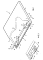
- X-ray cassette 1 shows the sectional view of an X-ray cassette 1 according to the invention
- X-ray cassette 1 has a housing with an end face 4 and two perpendicular to this end face 4 lying shorter side surfaces 5 and 6.
- a storage phosphor plate 10 Inside the X-ray cassette 1 is a storage phosphor plate 10.
- This storage phosphor plate 10 is used to store X-ray information. The X-ray information were in the storage phosphor plate using X-rays stored.
- the front side 4 of the X-ray cassette 1 contains a slit-shaped one Opening 2. About this slit-shaped opening 2, which extends approximately over the entire The width of the end face 4 extends, the storage phosphor plate from the X-ray cassette 1 can be pulled out.
- the X-ray cassette 1 has a closure 3.
- This closure 3 can have a Movement mechanism in the vertical direction within the X-ray cassette 1 be moved. As a result, the opening 2 can be closed by means of the closure 3 open
- the first Contour 11 is in the left edge region of the side adjoining the end face 4 Storage phosphor plate 10 attached.
- the second contour 12 is in the right edge area the surface of the storage phosphor plate adjoining the end face 4 10 attached.
- the two contours 11 and 12 are formed by cutouts, into which a gripper arm for pulling out the storage phosphor plate 10 the X-ray cassette 1 can intervene.
- This gripper arm is part of a device for reading out the x-ray information stored in the storage phosphor plate 10.
- the X-ray cassette is used to read out this X-ray information 1 inserted into the reading device.
- the gripper arms then drive through the open opening 2 in the X-ray cassette 1 and grip the storage phosphor plate 10 on the two contours 11 and 12.
- two contours 13 and 14 are arranged, those for fixing the storage phosphor plate 10 within the X-ray cassette 1 serve.
- the two Rockers 21 and 22 are rotatably mounted on a control slide 20.
- On the two Rockers 21 and 22 attached fixing bolts move to fix the storage phosphor plate 10 in the two contours 13 and 14.
- the control slide 20 arranged within the X-ray cassette 1 extends essentially over the entire width of the X-ray cassette 1.
- the control slide 20 serves to open and close the closure 3 and also for fixing and non-fixing of the storage phosphor plate 10 in the X-ray cassette 1.
- the control slide 20 has a link 23.
- This link 23 serves as an actuating means for actuating the control slide 20.
- Actuating pin 40 can be moved against the end side of the link 23 the spool in a direction A, d. H. towards the right side surface 5 the X-ray cassette 1.
- actuating pin 40 To move the spool To enable 20 by means of the actuating pin 40 is within the left Side surface 6 of the X-ray cassette 1 in the region of the end surface of the link 23 Actuating hole introduced in the side surface 6. About this actuation hole the actuating pin 40 can move into the X-ray cassette 1 and against the end face press the backdrop 23. The force applied by the actuating pin 40 in direction A causes the control spool 20 to be moved in direction A.
- a return spring (not shown) can be attached to the control slide 20 be that exerts a force in a direction B that is opposite to the direction A. is.
- a return spring can be attached to the control slide 20 be that exerts a force in a direction B that is opposite to the direction A. is.
- actuating pin 40 in the direction B causes Return spring a displacement of the spool 20 in this direction B.
- a displacement of the control spool 20 both in direction A and in Direction B can be effected.
- Fig. 1 there is an operating hole 7 in the right side surface 5 shown.
- the contour 11 is used to grip the storage phosphor plate 10 by a gripper arm of the readout device.
- the contour 11 is here formed by means of an L-shaped recess 15 into which the gripper arm can move, to pull the storage phosphor plate 10 out of the X-ray cassette 1.
- the fixing contour 13 is attached to the right of the contour 11.
- the contour 13 will formed by means of a round opening 16 into which an attached to the rocker 21 Fixing bolt can retract to the storage phosphor plate 10 in the X-ray cassette 1 to fix.
- the two contours 11 and 13 can be independent of the Storage phosphor plate can be designed.
- Both form and material of the Contours 11 and 13 can differ from the shape and material of the storage phosphor plate differ.
- the two contours 11 and 13 are preferably made of hardened Metal. This is particularly wear-resistant. But it is also possible that Contours z. B. from in particular fiber-reinforced plastic.
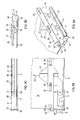
- FIG. 3 A-D show different views of the control slide 20 with the set first control stage, in which the opening 2 of the X-ray cassette 1 through the Closure 3 is closed and the storage phosphor plate 10 in the X-ray cassette 1 is fixed.
- FIG 3 A shows a section of a view of the left front area of FIG X-ray cassette 1 with the left part of the control slide 20 and the rocker 21 for fixing the storage phosphor plate 10 in the X-ray cassette 1.
- the fixing rocker 21 is rotatably connected to the control slide 20 via a pivot pin 30.
- the pivot pin 30 represents the axis of rotation for the fixing rocker 21
- Rocker 21 has a type of wing, at the end of which a fixing bolt 31 is attached.
- the fixing bolt 31 has a round cross section here. It protrudes downwards. H. in Direction of the storage phosphor plate 10, out of the wing of the rocker 21.
- the first control stage of the control slide 20 shown here is the fixing bolt 31 retracted into the fixing contour 13. This will make the storage phosphor plate 10 fixed in the X-ray cassette 1.
- the rocker 21 has a first rocker cam 32 and a second rocker cam 33 on.
- the two rocker cams 32 and 33 are triangular and open attached to the upper surface of the rocker 21.
- the control slide 20 contains two slot-shaped recesses 34 and 35.
- the first slot 34 is in one area above the cam 32 and the second one mounted in the right part of the rocker 21 Slot 35 in an area above that in the left part of the rocker 21 second cam 33 attached.
- the two slots 34 and 35 each have such Width that the cams 32 and 33 engage in the two slots 34 and 35, respectively can.
- 3A shows how the cam 32 engages in the slot 34 and through the slot 34 of the control slide 20 protrudes upwards.
- the backdrop 23 is located at the left end of the control slide 20.
- the backdrop 23 has a large width in its end region. This is followed by an area in which the backdrop tapers to a small width. In this tapered In the area of the backdrop 23, the backdrop 23 has a slope. The scenery 23 thereby becomes linear from the wide area to the small width area transferred.
- FIG. 3 A-D there is the control slide in the first tax stage.
- the facial expressions of opening and closing the Closure 3 contains a motion converter 38 which on the side surface 6 of the X-ray cassette 1 is rotatably mounted.
- the hook of the motion converter 38 engages on the side surface of the backdrop 23.
- a linearly guided push rod 37 appropriate. When turning the motion converter 38, it bumps against the Push rod 37.
- the driver 36 This picks up the rotary movement and converts it into a linear movement in the direction of a driver 36.
- the driver 36 is located to the right of the push rod 37 and is on the side surface 6 of the X-ray cassette 1 rotatably mounted.
- the linear movement of the push rod 37 leads to the fact that this presses against the driver 36. This then begins to turn.
- the Linear movement of the push rod 37 is thus in a by the driver 36 Rotational movement implemented.
- the driver 36 engages at the left end of the closure 3 in this one, so that the closure 3 in the vertical direction upwards emotional.
- the motion converter engages on the Area of the backdrop 23 with the small width.
- the position of the hook relative to the The backdrop 23 in FIGS. 3A and 3B is indicated by the position S1 of the backdrop 23 shown.
- Position S1 indicates the setting of the first control level of the Control spool 20.
- Position S1 is thus activated by the engagement of the hook of the motion converter 38 on the area of the link 23 with the small width set.
- the closure 3 is in the lower position, so that the opening 2 is closed and the wing of the rocker 21 is down directed so that the fixing bolt 31 attached to the end of the wing into the fixing contour 13 engages.
- FIG. 3B shows a top view of the arrangement shown in FIG. 3A.
- 3 B is the configuration of the link 23 and the setting of the position S1 shown clearly visible.
- FIG. 3 C shows a front view of the arrangement according to FIG. 3 A.
- the alignment of the rocker 21 is well shown. It can be seen how the Fixing bolt 31 engages in the fixing contour 13.
- the one to the left of the pivot pin 30 Rocker cam 33 is located below the control slide 20 and Relative to the slot-shaped recess 35 laterally offset to the right.
- 3 D shows a side view of the arrangement according to FIG. 3 A.
- 3 D is the facial expressions with the driver 36, the rod 37 and the motion converter 38 for vertical displacement of the closure 3 is shown. Twisting the motion converter 38 and the driver 36 in a direction of rotation C causes the closure 3 to be raised.
- the rotation into Direction of rotation C is achieved by moving control spool 20 in direction A causes. From the area of narrow width of the link 23, the hook of the motion converter becomes 38 along the slope of the tapered area of the backdrop 23 moved until the hook in the area of the backdrop 23 with a large width has arrived. This position of the hook relative to the link 23 is given by the position S2 shown in Figures 3 A and 3 B.
- the caused by it Rotational movement of the motion converter 38 in the direction C is via the rod 37 transferred to the driver 36. This also moves in the direction of rotation C and against one of a return spring (not shown) in the opposite Direction of rotation applied force.
- FIGS. 4 A-D show four different views of the embodiment of the Control spool 20 with the set second control stage.
- the opening 2 of the X-ray cassette 1 is opened by means of the closure 3.
- the storage phosphor plate 10 is still in the X-ray cassette 1 fixed.
- FIG. 4 A shows, like FIG. 3 A, a view of the left front area the X-ray cassette 1 with the left part of the control slide 20 and the fixing rocker 21.
- FIG. 4B shows the top view of the arrangement shown in FIG. 4A.
- 4 C shows the front view of the arrangement shown in FIG. 4 A.
- 4 D shows the side view of the arrangement according to FIG. 4 A.
- rocker cam 32 still protrudes the slot 34 through, while the rocker cam 33 continues below the Control spool 20 and is positioned slightly laterally offset to the slot 35.
- the wing of the rocker 21 is therefore still in the direction of the storage phosphor plate 10 inclined so that the fixing bolt 31 attached to the end of the wing continues in the opening 16 of the fixing contour 13 engages and the storage phosphor plate 10 in the X-ray cassette 1 fixed. This is shown particularly clearly in FIG. 4C.
- FIGS. 5 A-D show different views of the embodiment of the Control spool 20 with set third control stage.
- the opening 2 of the X-ray cassette 1 is opened by means of the closure 3.
- the Storage phosphor plate 10 is no longer fixed in the X-ray cassette 1.
- the Control spool 20 and the link 23 attached to its left end moved another piece in direction A.
- the control slide 20 and the backdrop 23 are in FIGS. 5 A to 5 D in a position S3.
- This position S3 5 A and 5 B as the position of the hook of the motion converter 38 in FIGS Relation to the backdrop 23 shown.
- the motion converter 38 is located continue in the area of the backdrop 23 with a large width. This causes the Lock 3 is still in the upper position. This is particularly true in the Fig. 5 D shown clearly visible.
- the width of the link 23 at position S2 is identical to the width of the backdrop at position S3.
- the exemplary embodiments described with reference to the figures show how it works Because of the three-stage control slide 20 is possible, the three in a simple manner Control levels.
- a simple displacement of the control slide 20 causes opening and closing the closure 3 and fixing and non-fixing the storage phosphor plate 10 in the X-ray cassette 1. Due to the three-stage Control slide 20 can in particular be ensured that the X-ray cassette 1 in a device for reading out the storage phosphor plate 10 can be opened and at the same time the storage phosphor plate 10 continues is fixed and retained in the X-ray cassette 1.
- the storage phosphor plate 10 can initially be the storage phosphor plate 10 grasp the contours 11 and 12 before fixing the storage phosphor plate 10 is canceled. Losing the storage phosphor plate 10 when transporting within the device for reading out can thus advantageously be avoided.
Landscapes
- Physics & Mathematics (AREA)
- General Physics & Mathematics (AREA)
- Radiography Using Non-Light Waves (AREA)
- Conversion Of X-Rays Into Visible Images (AREA)
Abstract
Description
- Fig. 1
- eine Schnittdarstellung eines Ausführungsbeispiels einer erfindungsgemäßen Röntgenkassette,
- Fig. 2
- ein Beispiel zweier an einer Speicherleuchtstoffplatte angebrachter Konturen,
- Fig. 3 A-D
- unterschiedliche Ansichten eines Ausführungsbeispiels eines Steuerschiebers mit eingestellter erster Steuerstufe,
- Fig. 4A-D
- unterschiedliche Ansichten des Ausführungsbeispiels des Steuerschiebers mit eingestellter zweiter Steuerstufe und
- Fig. 5A-D
- unterschiedliche Ansichten des Ausführungsbeispiels des Steuerschiebers mit eingestellter dritter Steuerstufe.
Claims (9)
- Kassette (1) zur Aufnahme einer Speicherleuchtstoffplatte (10) zum Abspeichern von Bildinformationen, wobei die Kassette (1)
einen Verschluss (3) zum Öffnen und Schließen einer Öffnung (2) der Kassette (1) und
ein Steuermittel (20) zum Betätigen des Verschlusses (3) aufweist,
dadurch gekennzeichnet, dass
die Kassette (1) ein Fixiermittel (21, 22, 31) zum Fixieren der Speicherleuchtstoffplatte (10) in der Kassette (1) aufweist und
mittels des Steuermittels (20) wenigstens drei Steuerstufen (S1, S2, S3) einstellbar sind, wobei
in einer ersten Steuerstufe (S1) die Öffnung (2) mittels des Verschlusses (3) geschlossen ist und das Fixiermittel (21, 22, 31) so eingestellt ist, dass es die Speicherleuchtstoffplatte (10) in der Kassette (1) fixiert,
in einer zweiten Steuerstufe (S2) die Öffnung (2) geöffnet ist und das Fixiermittel (21, 22, 31) so eingestellt ist, dass es die Speicherleuchtstoffplatte (10) in der Kassette (1) fixiert, und
in einer dritten Steuerstufe (S3) die Öffnung (2) geöffnet ist und das Fixiermittel (21, 22, 31) so eingestellt ist, dass das Fixieren der Speicherleuchtstoffplatte (10) in der Kassette (1) aufgehoben ist. - Kassette nach Anspruch 1, dadurch gekennzeichnet, dass das Steuermittel (20) so ausgestaltet ist, dass die wenigstens drei Steuerstufen (S1, S2, S3) nacheinander in aufsteigender Reihenfolge (S1, S2, S3), d. h. zunächst die erste (S1), dann die zweite (S2) und anschließend die dritte (S3) Steuerstufe, oder in absteigender Reihenfolge (S3, S2, S1), d. h. zunächst die dritte (S3), dann die zweite (S2) und anschließend die erste (S1) Steuerstufe, einstellbar sind.
- Kassette nach Anspruch 1 oder Anspruch 2, dadurch gekennzeichnet, dass sie ein Betätigungsmittel (7, 23) zum Betätigen des Steuermittels (20) aufweist.
- Kassette nach Anspruch 3, dadurch gekennzeichnet, dass das Betätigungsmittel (7, 23) zu einer Seitenfläche (5, 6) der Kassette (1) hin angeordnet ist.
- Kassette nach einem der vorhergehenden Ansprüche, dadurch gekennzeichnet, dass sie zwei Betätigungsmittel (7, 23) zum Betätigen des Steuermittels (20) aufweist.
- Kassette nach Anspruch 5, dadurch gekennzeichnet, dass das erste Betätigungsmittel (23) zu einer ersten Seitenfläche (6) und das zweite Betätigungsmittel (7) zu einer zweiten Seitenfläche (5) der Kassette (1) hin angeordnet ist und die erste Seitenfläche (6) und die zweite Seitenfläche (5) gegenüberliegende Seitenflächen sind.
- Kassette nach Anspruch 5 oder Anspruch 6, dadurch gekennzeichnet, dass mittels des ersten Betätigungsmittels (23) die Öffnung (2) mittels des Verschlusses (3) geöffnet und das Fixiermittel (21, 22, 31) so eingestellt ist, dass das Fixieren der Speicherleuchtstoffplatte (10) in der Kassette (1) aufgehoben ist, und mittels des zweiten Betätigungsmittels die Öffnung (2) mittels des Verschlusses (3) geschlossen und das Fixiermittel (21, 22, 31) so eingestellt wird, dass es die Speicherleuchtstoffplatte (10) in der Kassette (1) fixiert.
- Kassette nach einem der vorhergehenden Ansprüche, dadurch gekennzeichnet, dass das Steuermittel einen Steuerschieber (20) aufweist, der so ausgestaltet ist, dass die Steuerstufen (S1, S2, S3) des Steuermittels durch Verschieben des Steuerschiebers (20) nacheinander einstellbar sind.
- Verfahren zum Öffnen und Schließen einer Öffnung (2) einer Kassette (1) zur Aufnahme einer Speicherleuchtstoffplatte (10), die zum Abspeichern von Bildinformationen dient, wobei mittels eines Steuermittels (20) ein Verschluss (3) betätigt wird,
dadurch gekennzeichnet, dass
mittels des Steuermittels (20) ein Fixiermittel (21, 22, 31) zum Fixieren der Speicherleuchtstoffplatte (10) in der Kassette (1) angesteuert wird, und das Steuermittel (20) wenigstens drei Steuerstufen (S1, S2, S3) einstellt, so dass in einer ersten Steuerstufe (S1) die Öffnung (2) mittels des Verschlusses (3) geschlossen und die Speicherleuchtstoffplatte (10) in der Kassette (1) fixiert wird,
in einer zweiten Steuerstufe (S2) die Öffnung (2) geöffnet wird und die Speicherleuchtstoffplatte (10) in der Kassette (1) fixiert bleibt, und
in einer dritten Steuerstufe (S3) die Öffnung (2) geöffnet bleibt und das Fixieren der Speicherleuchtstoffplatte (10) in der Kassette (1) aufgehoben wird.
Priority Applications (3)
| Application Number | Priority Date | Filing Date | Title |
|---|---|---|---|
| AT01130500T ATE349032T1 (de) | 2001-12-20 | 2001-12-20 | Röntgenkassette für eine speicherleuchtstofffolie |
| DE50111703T DE50111703D1 (de) | 2001-12-20 | 2001-12-20 | Röntgenkassette für eine Speicherleuchtstofffolie |
| EP01130500A EP1324117B1 (de) | 2001-12-20 | 2001-12-20 | Röntgenkassette für eine Speicherleuchtstofffolie |
Applications Claiming Priority (1)
| Application Number | Priority Date | Filing Date | Title |
|---|---|---|---|
| EP01130500A EP1324117B1 (de) | 2001-12-20 | 2001-12-20 | Röntgenkassette für eine Speicherleuchtstofffolie |
Publications (2)
| Publication Number | Publication Date |
|---|---|
| EP1324117A1 true EP1324117A1 (de) | 2003-07-02 |
| EP1324117B1 EP1324117B1 (de) | 2006-12-20 |
Family
ID=8179629
Family Applications (1)
| Application Number | Title | Priority Date | Filing Date |
|---|---|---|---|
| EP01130500A Expired - Lifetime EP1324117B1 (de) | 2001-12-20 | 2001-12-20 | Röntgenkassette für eine Speicherleuchtstofffolie |
Country Status (3)
| Country | Link |
|---|---|
| EP (1) | EP1324117B1 (de) |
| AT (1) | ATE349032T1 (de) |
| DE (1) | DE50111703D1 (de) |
Cited By (6)
| Publication number | Priority date | Publication date | Assignee | Title |
|---|---|---|---|---|
| EP1531359A1 (de) * | 2003-11-14 | 2005-05-18 | Agfa-Gevaert AG | Kassette für eine Speicherleuchtstoffplatte |
| EP1533654A1 (de) * | 2003-11-14 | 2005-05-25 | Agfa-Gevaert AG | Kassette für eine Speicherleuchtstoffplatte |
| EP1640800A1 (de) * | 2004-09-22 | 2006-03-29 | Agfa-Gevaert HealthCare GmbH | Vorrichtung zum Auslesen von in einer Speicherleuchtstoffplatte gespeicherten Röntgeninformation |
| US7256413B2 (en) | 2004-09-22 | 2007-08-14 | Agfa-Gevaert Aktiengesellschaft | Device and process for reading out X-ray information stored in a phosphor plate |
| US7514697B2 (en) | 2004-05-21 | 2009-04-07 | Agfa-Gevaert Healthcare Gmbh | Storage phosphor plate for the storage of X-ray information |
| US7619236B2 (en) | 2005-12-29 | 2009-11-17 | Agfa-Gevaert Healthcare Gmbh | Driving apparatus for optical scanning device |
Citations (3)
| Publication number | Priority date | Publication date | Assignee | Title |
|---|---|---|---|---|
| GB1361014A (en) * | 1970-07-07 | 1974-07-24 | Productron Inc | Film sheet dispenser |
| US5441251A (en) * | 1991-04-19 | 1995-08-15 | Fuji Photo Film Co., Ltd. | Sheet article containing cassette and system |
| JPH11334896A (ja) * | 1998-03-25 | 1999-12-07 | Fuji Photo Film Co Ltd | シ―ト体の飛び出し防止構造 |
-
2001
- 2001-12-20 AT AT01130500T patent/ATE349032T1/de not_active IP Right Cessation
- 2001-12-20 EP EP01130500A patent/EP1324117B1/de not_active Expired - Lifetime
- 2001-12-20 DE DE50111703T patent/DE50111703D1/de not_active Expired - Lifetime
Patent Citations (3)
| Publication number | Priority date | Publication date | Assignee | Title |
|---|---|---|---|---|
| GB1361014A (en) * | 1970-07-07 | 1974-07-24 | Productron Inc | Film sheet dispenser |
| US5441251A (en) * | 1991-04-19 | 1995-08-15 | Fuji Photo Film Co., Ltd. | Sheet article containing cassette and system |
| JPH11334896A (ja) * | 1998-03-25 | 1999-12-07 | Fuji Photo Film Co Ltd | シ―ト体の飛び出し防止構造 |
Non-Patent Citations (1)
| Title |
|---|
| PATENT ABSTRACTS OF JAPAN vol. 2000, no. 03 30 March 2000 (2000-03-30) * |
Cited By (8)
| Publication number | Priority date | Publication date | Assignee | Title |
|---|---|---|---|---|
| EP1531359A1 (de) * | 2003-11-14 | 2005-05-18 | Agfa-Gevaert AG | Kassette für eine Speicherleuchtstoffplatte |
| EP1533654A1 (de) * | 2003-11-14 | 2005-05-25 | Agfa-Gevaert AG | Kassette für eine Speicherleuchtstoffplatte |
| US7459691B2 (en) | 2003-11-14 | 2008-12-02 | Agfa-Gevaert Healthcare Gmbh | Cassette for a storage fluorescent screen |
| US7514697B2 (en) | 2004-05-21 | 2009-04-07 | Agfa-Gevaert Healthcare Gmbh | Storage phosphor plate for the storage of X-ray information |
| EP1640800A1 (de) * | 2004-09-22 | 2006-03-29 | Agfa-Gevaert HealthCare GmbH | Vorrichtung zum Auslesen von in einer Speicherleuchtstoffplatte gespeicherten Röntgeninformation |
| US7256413B2 (en) | 2004-09-22 | 2007-08-14 | Agfa-Gevaert Aktiengesellschaft | Device and process for reading out X-ray information stored in a phosphor plate |
| US7315040B2 (en) | 2004-09-22 | 2008-01-01 | Agfa-Gevaert Healthcare Gmbh | Device for reading out X-ray information stored in a phosphor plate |
| US7619236B2 (en) | 2005-12-29 | 2009-11-17 | Agfa-Gevaert Healthcare Gmbh | Driving apparatus for optical scanning device |
Also Published As
| Publication number | Publication date |
|---|---|
| EP1324117B1 (de) | 2006-12-20 |
| DE50111703D1 (de) | 2007-02-01 |
| ATE349032T1 (de) | 2007-01-15 |
Similar Documents
| Publication | Publication Date | Title |
|---|---|---|
| DE69831590T2 (de) | Schloss mit falle und riegel mit gleichzeitiger schliessbewegung von falle und riegel | |
| DE3815890A1 (de) | Fernbetaetigter riegelmechanismus | |
| DE4327782A1 (de) | Türverschlußvorrichtung mit einem Ein-Bewegungs-Türöffnungsmechanismus | |
| DE102008048712A1 (de) | Schlosseinheit mit Mehrklinken-Gesperre | |
| DE102012106393A1 (de) | Türverriegelungsvorrichtung für ein Fahrzeug | |
| DE4324300A1 (de) | Antipanik-Türschloß | |
| DE3609043C2 (de) | Elektrische Sicherheitsschaltvorrichtung | |
| DE3715268A1 (de) | Betaetigungsvorrichtung fuer ein fahrzeugdach | |
| DE202004001916U1 (de) | Mechanismus für ein Schiebedach | |
| DE4026155C2 (de) | Riegelbetätigungsvorrichtung für Türen o. dgl. | |
| EP1324117B1 (de) | Röntgenkassette für eine Speicherleuchtstofffolie | |
| DE19845125A1 (de) | Fahrzeugtürverriegelungsvorrichtung mit Selbstrückstellmechanismus | |
| EP0021406A1 (de) | Filmkassette mit einem Fenster zum Einbelichten von Daten | |
| DE3875642T2 (de) | Elektrisches sicherheitsschloss. | |
| EP0995866B1 (de) | Schloss, insbesondere Treibstangenschloss | |
| DE102008034638A1 (de) | Schlosseinheit mit blockierter Sperrklinke | |
| DE3507349A1 (de) | Schloss | |
| DE3027462A1 (de) | Mit riegel und falle versehenes einsteckschloss | |
| EP3569800A1 (de) | Schloss, insbesondere sperrfallenschloss | |
| DE69918938T2 (de) | Schlüsseleinführungsvorrichtung | |
| EP0913549B1 (de) | Türschloss mit Fallensperre | |
| DE3002504C2 (de) | Kassette für Röntgenaufnahmen | |
| DE60307036T2 (de) | Verriegelungssystem für Fenster, Türen oder dergleichen, Verriegelungselement und Schliessblech | |
| EP1531359A1 (de) | Kassette für eine Speicherleuchtstoffplatte | |
| EP1324118B1 (de) | Speicherleuchtstofffolie für Röntgenaufnahmen |
Legal Events
| Date | Code | Title | Description |
|---|---|---|---|
| PUAI | Public reference made under article 153(3) epc to a published international application that has entered the european phase |
Free format text: ORIGINAL CODE: 0009012 |
|
| AK | Designated contracting states |
Designated state(s): AT BE CH CY DE DK ES FI FR GB GR IE IT LI LU MC NL PT SE TR |
|
| AX | Request for extension of the european patent |
Extension state: AL LT LV MK RO SI |
|
| 17P | Request for examination filed |
Effective date: 20040102 |
|
| AKX | Designation fees paid |
Designated state(s): AT BE CH CY DE DK ES FI FR GB GR IE IT LI LU MC NL PT SE TR |
|
| RAP1 | Party data changed (applicant data changed or rights of an application transferred) |
Owner name: AGFA-GEVAERT HEALTHCARE GMBH |
|
| GRAP | Despatch of communication of intention to grant a patent |
Free format text: ORIGINAL CODE: EPIDOSNIGR1 |
|
| GRAS | Grant fee paid |
Free format text: ORIGINAL CODE: EPIDOSNIGR3 |
|
| GRAA | (expected) grant |
Free format text: ORIGINAL CODE: 0009210 |
|
| AK | Designated contracting states |
Kind code of ref document: B1 Designated state(s): AT BE CH CY DE DK ES FI FR GB GR IE IT LI LU MC NL PT SE TR |
|
| PG25 | Lapsed in a contracting state [announced via postgrant information from national office to epo] |
Ref country code: IT Free format text: LAPSE BECAUSE OF FAILURE TO SUBMIT A TRANSLATION OF THE DESCRIPTION OR TO PAY THE FEE WITHIN THE PRE;WARNING: LAPSES OF ITALIAN PATENTS WITH EFFECTIVE DATE BEFORE 2007 MAY HAVE OCCURRED AT ANY TIME BEFORE 2007. THE CORRECT EFFECTIVE DATE MAY BE DIFFERENT FROM THE ONE RECORDED.SCRIBED TIME-LIMIT Effective date: 20061220 Ref country code: DK Free format text: LAPSE BECAUSE OF FAILURE TO SUBMIT A TRANSLATION OF THE DESCRIPTION OR TO PAY THE FEE WITHIN THE PRESCRIBED TIME-LIMIT Effective date: 20061220 Ref country code: IE Free format text: LAPSE BECAUSE OF FAILURE TO SUBMIT A TRANSLATION OF THE DESCRIPTION OR TO PAY THE FEE WITHIN THE PRESCRIBED TIME-LIMIT Effective date: 20061220 Ref country code: NL Free format text: LAPSE BECAUSE OF FAILURE TO SUBMIT A TRANSLATION OF THE DESCRIPTION OR TO PAY THE FEE WITHIN THE PRESCRIBED TIME-LIMIT Effective date: 20061220 Ref country code: FI Free format text: LAPSE BECAUSE OF FAILURE TO SUBMIT A TRANSLATION OF THE DESCRIPTION OR TO PAY THE FEE WITHIN THE PRESCRIBED TIME-LIMIT Effective date: 20061220 |
|
| REG | Reference to a national code |
Ref country code: GB Ref legal event code: FG4D Free format text: NOT ENGLISH |
|
| PG25 | Lapsed in a contracting state [announced via postgrant information from national office to epo] |
Ref country code: MC Free format text: LAPSE BECAUSE OF NON-PAYMENT OF DUE FEES Effective date: 20061231 Ref country code: BE Free format text: LAPSE BECAUSE OF NON-PAYMENT OF DUE FEES Effective date: 20061231 Ref country code: CH Free format text: LAPSE BECAUSE OF NON-PAYMENT OF DUE FEES Effective date: 20061231 Ref country code: LI Free format text: LAPSE BECAUSE OF NON-PAYMENT OF DUE FEES Effective date: 20061231 |
|
| GBT | Gb: translation of ep patent filed (gb section 77(6)(a)/1977) |
Effective date: 20061220 |
|
| REG | Reference to a national code |
Ref country code: CH Ref legal event code: EP |
|
| REF | Corresponds to: |
Ref document number: 50111703 Country of ref document: DE Date of ref document: 20070201 Kind code of ref document: P |
|
| REG | Reference to a national code |
Ref country code: IE Ref legal event code: FG4D Free format text: LANGUAGE OF EP DOCUMENT: GERMAN |
|
| PG25 | Lapsed in a contracting state [announced via postgrant information from national office to epo] |
Ref country code: SE Free format text: LAPSE BECAUSE OF FAILURE TO SUBMIT A TRANSLATION OF THE DESCRIPTION OR TO PAY THE FEE WITHIN THE PRESCRIBED TIME-LIMIT Effective date: 20070320 |
|
| PG25 | Lapsed in a contracting state [announced via postgrant information from national office to epo] |
Ref country code: ES Free format text: LAPSE BECAUSE OF FAILURE TO SUBMIT A TRANSLATION OF THE DESCRIPTION OR TO PAY THE FEE WITHIN THE PRESCRIBED TIME-LIMIT Effective date: 20070331 |
|
| PG25 | Lapsed in a contracting state [announced via postgrant information from national office to epo] |
Ref country code: PT Free format text: LAPSE BECAUSE OF FAILURE TO SUBMIT A TRANSLATION OF THE DESCRIPTION OR TO PAY THE FEE WITHIN THE PRESCRIBED TIME-LIMIT Effective date: 20070423 |
|
| ET | Fr: translation filed | ||
| NLV1 | Nl: lapsed or annulled due to failure to fulfill the requirements of art. 29p and 29m of the patents act | ||
| REG | Reference to a national code |
Ref country code: CH Ref legal event code: PL |
|
| PLBE | No opposition filed within time limit |
Free format text: ORIGINAL CODE: 0009261 |
|
| STAA | Information on the status of an ep patent application or granted ep patent |
Free format text: STATUS: NO OPPOSITION FILED WITHIN TIME LIMIT |
|
| 26N | No opposition filed |
Effective date: 20070921 |
|
| BERE | Be: lapsed |
Owner name: AGFA-GEVAERT HEALTHCARE G.M.B.H. Effective date: 20061231 |
|
| PG25 | Lapsed in a contracting state [announced via postgrant information from national office to epo] |
Ref country code: AT Free format text: LAPSE BECAUSE OF NON-PAYMENT OF DUE FEES Effective date: 20061220 |
|
| PG25 | Lapsed in a contracting state [announced via postgrant information from national office to epo] |
Ref country code: GR Free format text: LAPSE BECAUSE OF FAILURE TO SUBMIT A TRANSLATION OF THE DESCRIPTION OR TO PAY THE FEE WITHIN THE PRESCRIBED TIME-LIMIT Effective date: 20070321 |
|
| PGFP | Annual fee paid to national office [announced via postgrant information from national office to epo] |
Ref country code: FR Payment date: 20071129 Year of fee payment: 7 Ref country code: GB Payment date: 20071130 Year of fee payment: 7 |
|
| PG25 | Lapsed in a contracting state [announced via postgrant information from national office to epo] |
Ref country code: LU Free format text: LAPSE BECAUSE OF NON-PAYMENT OF DUE FEES Effective date: 20061220 Ref country code: TR Free format text: LAPSE BECAUSE OF FAILURE TO SUBMIT A TRANSLATION OF THE DESCRIPTION OR TO PAY THE FEE WITHIN THE PRESCRIBED TIME-LIMIT Effective date: 20061220 |
|
| PG25 | Lapsed in a contracting state [announced via postgrant information from national office to epo] |
Ref country code: CY Free format text: LAPSE BECAUSE OF FAILURE TO SUBMIT A TRANSLATION OF THE DESCRIPTION OR TO PAY THE FEE WITHIN THE PRESCRIBED TIME-LIMIT Effective date: 20061220 |
|
| GBPC | Gb: european patent ceased through non-payment of renewal fee |
Effective date: 20081220 |
|
| REG | Reference to a national code |
Ref country code: FR Ref legal event code: ST Effective date: 20090831 |
|
| PG25 | Lapsed in a contracting state [announced via postgrant information from national office to epo] |
Ref country code: GB Free format text: LAPSE BECAUSE OF NON-PAYMENT OF DUE FEES Effective date: 20081220 |
|
| PG25 | Lapsed in a contracting state [announced via postgrant information from national office to epo] |
Ref country code: FR Free format text: LAPSE BECAUSE OF NON-PAYMENT OF DUE FEES Effective date: 20081231 |
|
| REG | Reference to a national code |
Ref country code: DE Ref legal event code: R084 Ref document number: 50111703 Country of ref document: DE Effective date: 20130212 |
|
| PGFP | Annual fee paid to national office [announced via postgrant information from national office to epo] |
Ref country code: DE Payment date: 20140922 Year of fee payment: 14 |
|
| REG | Reference to a national code |
Ref country code: DE Ref legal event code: R119 Ref document number: 50111703 Country of ref document: DE |
|
| PG25 | Lapsed in a contracting state [announced via postgrant information from national office to epo] |
Ref country code: DE Free format text: LAPSE BECAUSE OF NON-PAYMENT OF DUE FEES Effective date: 20160701 |