EP1533654A1 - Kassette für eine Speicherleuchtstoffplatte - Google Patents
Kassette für eine Speicherleuchtstoffplatte Download PDFInfo
- Publication number
- EP1533654A1 EP1533654A1 EP03104198A EP03104198A EP1533654A1 EP 1533654 A1 EP1533654 A1 EP 1533654A1 EP 03104198 A EP03104198 A EP 03104198A EP 03104198 A EP03104198 A EP 03104198A EP 1533654 A1 EP1533654 A1 EP 1533654A1
- Authority
- EP
- European Patent Office
- Prior art keywords
- cassette
- shutter blade
- opening
- cassette according
- storage phosphor
- Prior art date
- Legal status (The legal status is an assumption and is not a legal conclusion. Google has not performed a legal analysis and makes no representation as to the accuracy of the status listed.)
- Granted
Links
- 238000003860 storage Methods 0.000 title claims description 34
- OAICVXFJPJFONN-UHFFFAOYSA-N Phosphorus Chemical compound [P] OAICVXFJPJFONN-UHFFFAOYSA-N 0.000 title claims description 33
- 238000003780 insertion Methods 0.000 claims abstract description 5
- 230000037431 insertion Effects 0.000 claims abstract description 5
- 241000446313 Lamella Species 0.000 claims description 9
- 239000000463 material Substances 0.000 claims description 7
- 239000011248 coating agent Substances 0.000 claims description 5
- 238000000576 coating method Methods 0.000 claims description 5
- 239000004809 Teflon Substances 0.000 claims description 4
- 229920006362 Teflon® Polymers 0.000 claims description 4
- 229910000639 Spring steel Inorganic materials 0.000 claims description 3
- 229910052782 aluminium Inorganic materials 0.000 claims description 2
- XAGFODPZIPBFFR-UHFFFAOYSA-N aluminium Chemical compound [Al] XAGFODPZIPBFFR-UHFFFAOYSA-N 0.000 claims description 2
- 229910052751 metal Inorganic materials 0.000 claims description 2
- 239000002184 metal Substances 0.000 claims description 2
- 230000000284 resting effect Effects 0.000 claims 1
- 230000008901 benefit Effects 0.000 description 5
- 238000004519 manufacturing process Methods 0.000 description 3
- 239000002131 composite material Substances 0.000 description 2
- 239000002872 contrast media Substances 0.000 description 2
- 230000003993 interaction Effects 0.000 description 2
- 238000012423 maintenance Methods 0.000 description 2
- 230000007246 mechanism Effects 0.000 description 2
- 230000008439 repair process Effects 0.000 description 2
- 208000032484 Accidental exposure to product Diseases 0.000 description 1
- 229910000838 Al alloy Inorganic materials 0.000 description 1
- 229920000049 Carbon (fiber) Polymers 0.000 description 1
- 208000036829 Device dislocation Diseases 0.000 description 1
- 231100000818 accidental exposure Toxicity 0.000 description 1
- 230000009471 action Effects 0.000 description 1
- 238000005452 bending Methods 0.000 description 1
- 230000015572 biosynthetic process Effects 0.000 description 1
- 239000008280 blood Substances 0.000 description 1
- 210000004369 blood Anatomy 0.000 description 1
- 239000004917 carbon fiber Substances 0.000 description 1
- 239000000969 carrier Substances 0.000 description 1
- 238000004140 cleaning Methods 0.000 description 1
- 230000000295 complement effect Effects 0.000 description 1
- 150000001875 compounds Chemical class 0.000 description 1
- 238000011109 contamination Methods 0.000 description 1
- 230000008878 coupling Effects 0.000 description 1
- 238000010168 coupling process Methods 0.000 description 1
- 238000005859 coupling reaction Methods 0.000 description 1
- 238000013461 design Methods 0.000 description 1
- 238000011161 development Methods 0.000 description 1
- 238000006073 displacement reaction Methods 0.000 description 1
- 230000003670 easy-to-clean Effects 0.000 description 1
- 230000000694 effects Effects 0.000 description 1
- 230000002996 emotional effect Effects 0.000 description 1
- 239000000835 fiber Substances 0.000 description 1
- 239000007788 liquid Substances 0.000 description 1
- 230000007257 malfunction Effects 0.000 description 1
- 238000000034 method Methods 0.000 description 1
- 238000003825 pressing Methods 0.000 description 1
- 230000008569 process Effects 0.000 description 1
- 230000005855 radiation Effects 0.000 description 1
- 238000007789 sealing Methods 0.000 description 1
- 230000006641 stabilisation Effects 0.000 description 1
- 238000011105 stabilization Methods 0.000 description 1
- 239000000725 suspension Substances 0.000 description 1
- 238000012549 training Methods 0.000 description 1
- 230000007704 transition Effects 0.000 description 1
Images
Classifications
-
- G—PHYSICS
- G03—PHOTOGRAPHY; CINEMATOGRAPHY; ANALOGOUS TECHNIQUES USING WAVES OTHER THAN OPTICAL WAVES; ELECTROGRAPHY; HOLOGRAPHY
- G03B—APPARATUS OR ARRANGEMENTS FOR TAKING PHOTOGRAPHS OR FOR PROJECTING OR VIEWING THEM; APPARATUS OR ARRANGEMENTS EMPLOYING ANALOGOUS TECHNIQUES USING WAVES OTHER THAN OPTICAL WAVES; ACCESSORIES THEREFOR
- G03B42/00—Obtaining records using waves other than optical waves; Visualisation of such records by using optical means
- G03B42/02—Obtaining records using waves other than optical waves; Visualisation of such records by using optical means using X-rays
- G03B42/04—Holders for X-ray films
Definitions
- the invention relates to a cassette, in particular an X-ray cassette, according to the preamble of claim 1 for receiving a storage phosphor plate.
- the cassette serves to receive a storage phosphor plate, in the a generated with the X-ray radiation image can be stored latent.
- the Storage phosphor plate is held in the cassette during transport and usually only for reading the stored image from the cassette taken.
- a cassette which is suitable for receiving such a Storage phosphor plate is used and is provided with an opening through which insert the storage phosphor plate in the cassette or from this can be seen.
- the known cassette is at its opening with a Closure provided between a closed position in which he opens closes, and a release position in which he the opening for insertion or Removing the storage phosphor plate releases, is adjustable.
- a closure serves here a extending over the length of the opening bar, which is provided at each of its ends with a bearing plate, which in turn at the Cassette are rotatably mounted.
- To operate the shutter is an actuating mechanism held in the cassette, which from outside the cassette to be operated by an actuator.
- a disadvantage of this known cassette is that the closure used the Opening insufficiently closes, especially if the cassette is bent becomes. Furthermore, the closure is due to its training in the release position only a portion of the opening free, causing the insertion or Removing the storage phosphor plate is made difficult.
- the invention solves the problem by a cassette having the features of claim 1.
- the closure can be pivoted the cassette mounted shutter blade used.
- the shutter blade extends extends over the entire length of the opening of the cassette and is in at least a trained on the cassette slot guide.
- the Slot guide is the shutter blade both in its closed position, in the it closes the opening, as well as defined in its release position at any time and reliably held in the cassette.
- the shutter blade in conjunction with their pivotability the opening area is opposite to the opening of the cassette according to the invention the cassette known from the prior art significantly increased. Further, by the fact that the shutter blade for guiding with their guided in the slot guide edges in the slot guide, a achieved particularly high light-tightness with closed shutter blade.
- the high light-tightness is even given when the shutter blade with comparatively large game is performed in the slot guide.
- the guided in the slot guide shutter blade especially in her Closed position, additional stabilization of the opening, so that too mechanical loads, causing a bending of the cassette in the direction lead their flat side, the opening is still closed light-tight.
- the guided in the slot guide shutter blade allows Also, that the shutter blade with comparatively little force in its release position can be moved. This is true even if the cassette is light is bent.
- the at least a slot guide arcuate, which in particular the swinging back and forth
- the shutter blade is facilitated when opening and closing.
- the shutter blade can over the entire closing or opening process defined be guided relative to the cassette.
- the cassette is also the shutter blade arched in their transverse to the pivot axis cross-section designed, i. It has an arcuate profile in cross section, which on the arcuate shape of the slot guide is adjusted.
- the shutter blade of a to produce flexible material Due to the elasticity of the material is achieved that the material due to its internal stress evenly to the Leading edge of the slot guide applies, so that the shutter blade in at least almost every position is guided light-tight in the slot guide.
- a metal sheet As particularly preferred has shown the use of a spring steel sheet.
- the spring steel sheet is optionally hardened and so elastic in its elasticity, that the shutter blade at loads within the elastic limit the material remains insensitive to external damage.
- the shutter blade is formed as an extruded profile.
- the formation of the shutter blade as an extruded profile has the advantage that the shutter blade in their dimensions and in their shape with high accuracy can be adapted to the course of the slot guide. simultaneously are such extruded profiles with relatively little effort to produce and have a corresponding design due to their resistance moment over a very high resistance to external Charges.
- the extruded profile is made of aluminum or a Made of aluminum alloy, so that the cassette is a comparatively small Has weight.
- sealing lamella made of composite material.
- fiber composites e.g. based on carbon fibers, especially suitable.
- the cassette is the Closing lamella at each of its two ends provided with a driver, with which it is rotatably mounted on the cassette.
- the driver can, for example be operated by a corresponding actuator to the Closing blade between its closed position and its release position and to move on.
- at least one of the drivers with one on the cassette provided elastic element in engagement that the shutter blade is biased in its release position or in its closed position. To this Way is achieved that the shutter blade, depending on how the driver is engaged with the elastic element, automatically in its release position or returns to its closed position as soon as the force entering the shutter blade held in the respective opposite operating position has, deleted.
- the shutter blade is mounted in the driver, so that at a rotational movement of the driver, the shutter blade at the same time in the Slotted guide can be performed without this tilting the shutter blade occurs in the slot guide.
- attaching the shutter blade to the drivers is also achieved that to be observed Tolerances in the production of the shutter blade and the production of the Slot guide can be relatively large, as by the relative mobility the locking lamella to the drivers also a tolerance compensation after assembly is guaranteed.
- the shutter blade can independently align in the slot guide.
- an actuator with which the Closing blade between its closed position and its release position adjusted can be, wherein the actuating device is an actuating element has, which can be actuated from the outside of the housing forth.
- the shutter blade for example when inserting the cassette in an X-ray apparatus or a reader, by hand or by an automatically actuated actuator open from the outside, so that a light seal even when opening and Closing the opening for removing and inserting the storage phosphor plate can be guaranteed once the cassette in an X-ray or reading device is used.
- the actuating device preferably has a control slide, which between a rest position in which he is biased in their release position Closing blade holds in its closed position, and an operating position is movable, in which he releases the shutter blade.
- a Spool valve has the advantage that the spool valve by linear Move is to be actuated, causing a malfunction of the actuator can almost be excluded.
- the spool is in this development by at least a provided on the cassette elastic element in its rest position biased, so that only by active actuation of the actuating element the actuator moves the shutter blade in its release position.
- the spool is in a particularly preferred embodiment of this Embodiment parallel to the longitudinal direction of the opening extending between the Rest position and the operating position movable. Furthermore, the Spool at least one control link, which with a slidable co-located control bolt cooperates.
- the control link is in this case designed that the spool when moving from its rest position in the actuated position pulls the control latch from the opening, so that the shutter blade held by the control latch in its closed position in moves their release position. If, however, the spool from its operating position shifted to its rest position, the control bar pushes, causing through the control link, the shutter blade in its closed position.
- the shutter blade or shutter blade together with the actuating device in to integrate a removable front part of the cassette, which releasably on the housing the cassette is attached.
- the attachment is preferably carried out by Screws.
- locking connections are also suitable.
- the shutter blade may optionally be coated with a non-stick coating, at least be coated in sections, making the shutter blade insensitive against soiling, for example by sticky liquids, such as Contrast agent, blood and the like, will.
- a coating material becomes special preferably Teflon used.
- Storage phosphor plates are used, with corresponding detent openings and holding openings or holding elements are provided, it is proposed to arrange a fixing device in the housing of the cassette near the opening.
- the fixing device is between a locking position, in the with the stored in the cassette storage phosphor plate or the at her provided holding elements, holding openings or locking openings in Engaging is adjustable, and an unlocking position in which they the storage phosphor plate releases.
- the Storage phosphor plate for example, immediately before removing the Storage phosphor plate from the cassette to lock, leaving the storage phosphor plate in the cassette assumes a defined position and an on the Device in which the cassette is inserted, provided handling device the Storage phosphor plate can record.
- the actuator is simultaneously to operate used the fixing device, wherein the actuating device at a Movement from its rest position to its operating position, the fixing device moved to its unlocked position while moving during a movement of its actuating position in its rest position, the fixing device in its locking position emotional.
- the fixing device is securely held in the cassette during transport.
- Pressing the fixing device by the actuator can be designed so be that the fixing even after opening the shutter blade the storage phosphor plate is still locked in a defined position.
- the Fixing device has a locking slide on which a corresponding Locking opening is provided, which with the retaining pin in Intervention can be brought.
- locking retaining pin locking opening is a secure locking and positioning of the storage phosphor plate in the Cassette in a simple way possible.
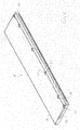
- Fig. 1 is a perspective view of a cassette 10 according to the invention for receiving a storage phosphor plate (not shown) for an X-ray apparatus shown.
- the cassette has a base plate 12 on which a cover 14 is attached.
- the cassette At its in Fig. 1 front longitudinal edge shown the cassette has an opening 16 through which the storage phosphor plate in the Insert cassette 10 or can be seen from this.
- the opening 16 is partially bounded by a front part 18, which by screws 20 at the Cover 14 of the cassette 10 is attached.
- a shutter blade 22 is arranged, which in each case at a pivotable at its two ends mounted on the base plate 12 driver 24 is mounted.
- the shutter blade 22 is between a closed position in which it closes the opening 16, and a release position in which it releases the opening 16.
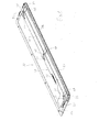
- each of the driver 24 by a tension spring 26 such biased that the two drivers 24, the shutter blade 22 in their Move release position when no closing force on the shutter blade 22 is exercised, as will be explained in detail later.
- the actuator 28 has a Control slide 30, which parallel to the longitudinal extent of the opening 16th slidably mounted between a rest position and an operating position is. Furthermore, the actuating device 28 has a tension spring 32, which biases the spool 30 in its rest position, so that the Control slide 30 only by applying a corresponding force its rest position is displaceable in the operating position.
- a total of three control slots 34 are formed from each of which is respectively engaged with a pin 36 of a control bar 38.
- Each of the control bar 38 is transverse to the direction of displacement of the spool 30 slidably mounted on the base plate 12 and can between a first position in which he the shutter blade 22 against the force of the tension spring 26 in its closed position, and a second position moves back and forth be, in which the control latch 38 is pulled away from the opening 16, so that the shutter blade 22 by the force of the tension spring 26 in its release position is moved.
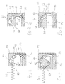
- Figs. 3 to 6 are two sections across the front part 18 and the Shutter 22 shown at different locations of the front part 18, wherein 3 and 5 show the shutter blade 22 in its closed position, while Figs. 4 and 6 illustrate the shutter blade 22 in its release position.
- the shutter blade 22 is provided with a Receiving opening 40 provided, with which it is attached to a hook 42 of the driver 24 is mounted. In a corresponding manner, the shutter blade 22 also hooked at its other end to the identically shaped driver 24.
- a strip 44 is provided, which is parallel extends to the opening 16 and limited to the top.
- the bar 44 is provided a rounded contact surface 46, on which the shutter blade 22 is guided with an edge 48.
- the front part 18 has on his Inside a contact surface 50, which is complementary to the contact surface 46 of the Strip 44 is formed.
- the two contact surfaces 46 and 50 form at at the Base plate 12 attached front part 18 a slot guide 52, in which the Closing blade 22 is defined guided.
- the shutter blade 22 is for this purpose in Cross-section arcuately shaped and the course of the two contact surfaces 46 and 50 adjusted.
- a parallel to the opening 16 extending receiving slot 54 is formed, which is arranged to the slot guide 52 such that the shutter blade 22 engages in its closed position in the receiving slot 54, as in the Fig. 3 and 5 is shown.
- under mechanical loading of the cassette 10 of the The top and / or bottom forth also gives the advantage that the Seal against light incidence is further increased, since in this case the shutter blade 22 engages even deeper into the receiving slot 54 or at least is held even tighter in this.
- the shutter blade 22 is extremely smooth and can not jam in the slot guide 52. If namely, the shutter blade 22 is not hooked into the driver 24, would by the pressure of the control bar 38 to the upper portion of the inner Bearing surface 50 of the front part 18 are pressed and could clamp there.
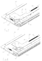
- the spool 30 is by the tension spring 32 in its rest position biased, in which it is located near the left side edge of the base plate 12 is. In this rest position, the spool 30 presses through the interaction the control gate 34 with the pin 36, the control latch 38 in the direction the opening 16, so that these the shutter blade 22 in its closed position hold against the force of the tension springs 26. This condition is for example shown in detail in FIG.
- the opening 16 to be opened - for example, after the cassette 10 in a device for reading the stored latent in the storage phosphor layer Image information has been introduced - is the spool 30th from the outside of the cassette 10, for example manually or with the aid of a corresponding Actuator, by a at the left end of the cassette 10th provided actuating element 56 (see FIG. This is the spool 30 is moved against the force of the tension spring 32 to the right, in particular is indicated by the arrow in Fig. 8, wherein by the interaction the control gate 34 with the pin 36, the control latch 38 to the rear be moved away from the opening 16.
- the shutter blade 22 in its closed position with the receiving slot 54th is engaged, it is further ensured that the opening 16 also sealed light-tight remains when the cartridge 10 outer deforming loads is suspended and bent, for example, when the cassette 10 for an x-ray under a patient on an uneven surface is arranged.
- the shutter blade 22 is preferably coated with Teflon, so that in Trap of contamination, for example by contrast agents, the shutter blade 22 is easy to clean, with the Teflon coating beyond the friction in the slot guide 52 is reduced.
- the shutter blade 22 is easily accessible and may, for example, for maintenance, cleaning or repair work, easily solved by the drivers 24 and connected to these again become.
Landscapes
- Physics & Mathematics (AREA)
- General Physics & Mathematics (AREA)
- Radiography Using Non-Light Waves (AREA)
- Conversion Of X-Rays Into Visible Images (AREA)
- Analysing Materials By The Use Of Radiation (AREA)
Abstract
Description
- Fig. 1
- eine perspektivische Darstellung einer erfindungsgemäßen Kassette;
- Fig. 2
- eine perspektivische Darstellung der Kassette in Fig. 1 mit entfernter Abdeckung;
- Fig. 3
- eine geschnittene Seitenansicht in vergrößerter Darstellung einer Verschlusslamelle mit Mitnehmer in ihrer Schließstellung;
- Fig. 4
- eine der Fig. 3 entsprechende, geschnittene Seitenansicht in vergrößerter Darstellung bei in die Freigabestellung bewegter Verschlusslamelle;
- Fig. 5
- eine geschnittene Seitenansicht in vergrößerter Darstellung der von einem Steuerriegel in ihrer Schließstellung gehaltenen Verschlusslamelle;
- Fig. 6
- eine der Fig. 5 entsprechende, geschnittene Seitenansicht in vergrößerter Darstellung der in der Schlitzführung geführten Verschlusslamelle in ihrer Freigabestellung;
- Fig. 7
- eine vergrößerte perspektivische Darstellung eines Ausschnittes der Kassette ohne Abdeckung, bei der die Verschlusslamelle in ihrer Schließstellung gehalten ist; und
- Fig. 8
- eine vergrößerte perspektivische Darstellung eines Ausschnittes der Kassette ohne Abdeckung, bei der die Verschlusslamelle in ihre Freigabestellung bewegt ist.
- 10
- Kassette
- 12
- Grundplatte
- 14
- Abdeckung
- 16
- Öffnung
- 18
- Frontteil
- 20
- Schrauben
- 22
- Verschlusslamelle
- 24
- Mitnehmer
- 26
- Zugfeder
- 28
- Betätigungseinrichtung
- 30
- Steuerschieber
- 32
- Zugfeder
- 34
- Steuerkulissen
- 36
- Zapfen
- 38
- Steuerriegel
- 40
- Aufnahmeöffnung
- 42
- Haken
- 44
- Leiste
- 46
- Anlagefläche
- 48
- Kante
- 50
- Anlagefläche
- 52
- Schlitzführung
- 54
- Aufnahmeschlitz
- 56
- Betätigungselement
Claims (19)
- Kassette, insbesondere Röntgenkassette, zur Aufnahme einer Speicherleuchtstoffplatte, mitdadurch gekennzeichnet, dasseiner Öffnung (16), durch welche die Speicherleuchtstoffplatte in die Kassette (10) einzuführen oder aus dieser zu entnehmen ist, undeinem Verschluss (22), der zwischen einer Schließstellung, in der er die Öffnung (16) verschließt, und einer Freigabestellung, in der er die Öffnung (16) zum Einführen oder Entnehmen der Speicherleuchtstoffplatte freigibt, verstellbar ist,
als Verschluss eine schwenkbar an der Kassette (10) gelagerte Verschlusslamelle (22) dient, welche sich über die gesamte Länge der Öffnung (16) erstreckt und in mindestens einer an der Kassette (10) ausgebildeten Schlitzführung (52) geführt ist. - Kassette nach Anspruch 1, dadurch gekennzeichnet, dass mindestens eine Schlitzführung (52) bogenförmig verläuft.
- Kassette nach Anspruch 2, dadurch gekennzeichnet, dass die Verschlusslamelle (22) in ihrem quer zur Schwenkachse verlaufenden Querschnitt einen bogenförmigen Verlauf aufweist.
- Kassette nach Anspruch 1, 2 oder 3, dadurch gekennzeichnet, dass die Verschlusslamelle (22) aus einem biegsamen Material, vorzugsweise einem Metallblech, besonders bevorzugt aus einem Federstahlblech, gefertigt ist.
- Kassette nach Anspruch 1, 2 oder 3, dadurch gekennzeichnet, dass die Verschlusslamelle (22) als Strangpressprofil, vorzugsweise aus Aluminium, gefertigt ist.
- Kassette nach mindestens einem der Ansprüche 1 bis 5, dadurch geken n-zeichnet, dass die Verschlusslamelle (22) an jedem ihrer beiden Enden einen Mitnehmer (24) aufweist, mit dem sie an der Kassette (10) drehbar gelagert ist.
- Kassette nach Anspruch 6, dadurch gekennzeichnet, dass zumindest einer der Mitnehmer (24) mit einem an der Kassette (10) vorgesehenen elastischen Element (26) derart in Einriff steht, dass die Verschlusslamelle (22) in ihre Freigabestellung oder in ihre Schließstellung vorgespannt ist.
- Kassette nach Anspruch 6 oder 7, dadurch gekennzeichnet, dass die Verschlusslamelle (22) in die Mitnehmer (24) eingehängt ist.
- Kassette nach mindestens einem der vorhergehenden Ansprüche, dadurch gekennzeichnet, dass gegenüber der Schlitzführung (52) an der Öffnung (16) ein Aufnahmeschlitz (54) vorgesehen ist, in welchen die Verschlußlamelle (22) eingreift, wenn sich diese in ihrer Schließstellung befindet.
- Kassette nach mindestens einem der vorhergehenden Ansprüche, dadurch gekennzeichnet, dass an der Kassette (10) eine Betätigungseinrichtung (28) zum Verstellen der Verschlusslamelle (22) zwischen ihrer Schließstellung und ihrer Freigabestellung vorgesehen ist, und dass die Betätigungseinrichtung (28) ein Betätigungselement (56) aufweist, welches von der Außenseite der Kassette (10) her betätigt werden kann.
- Kassette nach mindestens einem der vorhergehenden Ansprüche, dadurch gekennzeichnet, dass die Betätigungseinrichtung (28) einen Steuerschieber (30) aufweist, welcher zwischen einer Ruhestellung, in der er die in ihre Freigabestellung vorgespannte Verschlusslamelle (22) in ihrer Schließstellung hält, und einer Betätigungsstellung bewegbar ist, in der er die Verschlusslamelle (22) freigibt.
- Kassette nach Anspruch 11, dadurch gekennzeichnet, dass der Steuerschieber (30) durch mindestens ein an der Kassette (10) vorgesehenes elastisches Element (32) in seine Ruhestellung vorgespannt ist.
- Kassette nach einem der Ansprüche 11 oder 12, dadurch gekennzeichnet, dass der Steuerschieber (30) parallel zur Längsrichtung der Öffnung (16) verlaufend zwischen der Ruhestellung und der Betätigungsstellung verschiebbar ist, und dass der Steuerschieber (30) mindestens eine Steuerkulisse (34) aufweist, welche mit einem verschiebbar gelagerten Steuerriegel (36) derart zusammenwirkt, dass der Steuerschieber (30) bei einer Bewegung von seiner Ruhestellung in die Betätigungsstellung den Steuerriegel (36) von der Öffnung (16) wegzieht, so dass sich die von dem Steuerriegel (36) in ihrer Schließstellung gehaltene Verschlusslamelle (22) in ihre Freigabestellung bewegt, während der Steuerschieber (30) bei einer Bewegung von seiner Betätigungsstellung in die Ruhestellung den Steuerriegel (36) in Richtung der Öffnung (16) verschiebt, so dass der Steuerriegel (36) die Verschlusslamelle (22) in ihrer Schließstellung drückt.
- Kassette nach einem der vorhergehenden Ansprüche, dadurch gekennzeichnet, dass die Verschlusslamelle (22) oder die Verschlusslamelle (22) gemeinsam mit der Betätigungseinrichtung (28) in ein abnehmbares Frontteil (18) der Kassette (10) integriert ist bzw. sind, welches lösbar, vorzugsweise durch Schrauben, an der Kassette (10) befestigt ist.
- Kassette nach mindestens einem der vorhergehenden Ansprüche, dadurch gekennzeichnet, dass die Verschlusslamelle (22) mit einer Antihaftbeschichtung, vorzugsweise einer Teflonbeschichtung, zumindest abschnittsweise beschichtet ist.
- Kassette nach mindestens einem der vorhergehenden Ansprüche, dadurch gekennzeichnet, dass im Gehäuse der Kassette (10) nahe der Öffnung (16) eine Fixiereinrichtung angeordnet ist, welche zwischen einer Verriegelungsstellung, in der sie mit der in der Kassette (10) aufgenommenen Speicherleuchtstoffplatte in Eingriff ist, und einer Entriegelungsstellung verstellbar ist, in der sie die Speicherleuchtstoffplatte freigibt.
- Kassette nach den Ansprüchen 10 und 16, dadurch gekennzeichnet, dass die Betätigungseinrichtung (28) gleichzeitig zum Betätigen der Fixiereinrichtung dient und bei einer Bewegung von ihrer Ruhestellung in ihre Betätigungsstellung die Fixiereinrichtung in ihre Entriegelungsstellung bewegt, während sie bei einer Bewegung von ihrer Betätigungsstellung in ihre Ruhestellung die Fixiereinrichtung in ihre Verriegelungsstellung bewegt.
- Kassette nach mindestens einem der Ansprüche 15, 16 oder 17, dadurch gekennzeichnet, dass die Fixiereinrichtung einen Verriegelungsschieber aufweist, an dem eine Verriegelungsöffnung vorgesehen ist, welche mit einem von der Speicherleuchtstoffplatte abstehenden Haltezapfen zum Verriegeln in Eingriff bringbar ist.
- Kassette nach einem der vorhergehenden Ansprüche, dadurch gekennzeichnet, dass die Verschlusslamelle (22) an jedem ihrer beiden Enden an jeweils einer an der Kassette (10) ausgebildeten Schlitzführung geführt ist.
Priority Applications (3)
| Application Number | Priority Date | Filing Date | Title |
|---|---|---|---|
| EP03104198A EP1533654B1 (de) | 2003-11-14 | 2003-11-14 | Kassette für eine Speicherleuchtstoffplatte |
| DE50308860T DE50308860D1 (de) | 2003-11-14 | 2003-11-14 | Kassette für eine Speicherleuchtstoffplatte |
| AT03104198T ATE381726T1 (de) | 2003-11-14 | 2003-11-14 | Kassette für eine speicherleuchtstoffplatte |
Applications Claiming Priority (1)
| Application Number | Priority Date | Filing Date | Title |
|---|---|---|---|
| EP03104198A EP1533654B1 (de) | 2003-11-14 | 2003-11-14 | Kassette für eine Speicherleuchtstoffplatte |
Publications (2)
| Publication Number | Publication Date |
|---|---|
| EP1533654A1 true EP1533654A1 (de) | 2005-05-25 |
| EP1533654B1 EP1533654B1 (de) | 2007-12-19 |
Family
ID=34429503
Family Applications (1)
| Application Number | Title | Priority Date | Filing Date |
|---|---|---|---|
| EP03104198A Expired - Lifetime EP1533654B1 (de) | 2003-11-14 | 2003-11-14 | Kassette für eine Speicherleuchtstoffplatte |
Country Status (3)
| Country | Link |
|---|---|
| EP (1) | EP1533654B1 (de) |
| AT (1) | ATE381726T1 (de) |
| DE (1) | DE50308860D1 (de) |
Cited By (2)
| Publication number | Priority date | Publication date | Assignee | Title |
|---|---|---|---|---|
| US7256413B2 (en) | 2004-09-22 | 2007-08-14 | Agfa-Gevaert Aktiengesellschaft | Device and process for reading out X-ray information stored in a phosphor plate |
| US7619236B2 (en) | 2005-12-29 | 2009-11-17 | Agfa-Gevaert Healthcare Gmbh | Driving apparatus for optical scanning device |
Citations (3)
| Publication number | Priority date | Publication date | Assignee | Title |
|---|---|---|---|---|
| JPS5849937A (ja) * | 1981-09-18 | 1983-03-24 | Canon Inc | シ−トフイルム収納マガジン |
| US5065866A (en) * | 1990-11-21 | 1991-11-19 | Eastman Kodak Company | Storage phosphor cassette assembly |
| EP1324117A1 (de) * | 2001-12-20 | 2003-07-02 | Agfa-Gevaert AG | Röntgenkassette für eine Speicherleuchtstofffolie |
-
2003
- 2003-11-14 AT AT03104198T patent/ATE381726T1/de not_active IP Right Cessation
- 2003-11-14 DE DE50308860T patent/DE50308860D1/de not_active Expired - Lifetime
- 2003-11-14 EP EP03104198A patent/EP1533654B1/de not_active Expired - Lifetime
Patent Citations (3)
| Publication number | Priority date | Publication date | Assignee | Title |
|---|---|---|---|---|
| JPS5849937A (ja) * | 1981-09-18 | 1983-03-24 | Canon Inc | シ−トフイルム収納マガジン |
| US5065866A (en) * | 1990-11-21 | 1991-11-19 | Eastman Kodak Company | Storage phosphor cassette assembly |
| EP1324117A1 (de) * | 2001-12-20 | 2003-07-02 | Agfa-Gevaert AG | Röntgenkassette für eine Speicherleuchtstofffolie |
Non-Patent Citations (1)
| Title |
|---|
| PATENT ABSTRACTS OF JAPAN vol. 007, no. 134 (P - 203) 11 June 1983 (1983-06-11) * |
Cited By (2)
| Publication number | Priority date | Publication date | Assignee | Title |
|---|---|---|---|---|
| US7256413B2 (en) | 2004-09-22 | 2007-08-14 | Agfa-Gevaert Aktiengesellschaft | Device and process for reading out X-ray information stored in a phosphor plate |
| US7619236B2 (en) | 2005-12-29 | 2009-11-17 | Agfa-Gevaert Healthcare Gmbh | Driving apparatus for optical scanning device |
Also Published As
| Publication number | Publication date |
|---|---|
| DE50308860D1 (de) | 2008-01-31 |
| EP1533654B1 (de) | 2007-12-19 |
| ATE381726T1 (de) | 2008-01-15 |
Similar Documents
| Publication | Publication Date | Title |
|---|---|---|
| DE10253138B4 (de) | Türvorrichtung für ein Fahrzeug und Verfahren zum Steuern einer Bewegung einer Tür | |
| DE10014760B4 (de) | Heckscheibenrollo mit gefederten Rollen | |
| EP1189764B1 (de) | Ringordnermechanik | |
| DE9411278U1 (de) | Dachfenster mit einer Feststellvorrichtung | |
| DE102018205680A9 (de) | Wohnwagenfenster und Öffnungsmechanismus dafür | |
| EP0156379B1 (de) | Kassenlade für eine Registrierkasse | |
| DE102015114392A1 (de) | Vorrichtung zum Positionieren von zwei Schiebetüren und Möbel | |
| WO2005028798A1 (de) | Rolltor mit kollisionsschutz | |
| DE2333249B2 (de) | Bandkassette | |
| EP1900560B1 (de) | Rollosystem für ein Schiebedach | |
| EP1531359B1 (de) | Kassette für eine Speicherleuchtstoffplatte | |
| DE102005028957A1 (de) | Elektrischer Türöffner für Türen aus Glas | |
| EP1533654B1 (de) | Kassette für eine Speicherleuchtstoffplatte | |
| EP3921495B1 (de) | Betätigungsgetriebe für ein hebe-schiebeelement mit arretierbarem betätigungshebel sowie mit solch einem betätigungsgetriebe ausgestattetes hebe-schiebeelement | |
| DE60012385T2 (de) | Türklemmschlossvorrichtung | |
| DE102011000493A1 (de) | Schließvorrichtung für bewegbare Möbelteile | |
| EP0934555B1 (de) | Klappenanordnung für den zugriff zu einem papierweg von einzelblattdruckern und -kopierern | |
| DE19509590C1 (de) | Höhenverstellbare Runge | |
| DE1708430C2 (de) | Feststellvorrichtung für einen Kippflügel | |
| DE2333157B2 (de) | Kassettenwagen | |
| EP0167767A2 (de) | Verriegelungsvorrichtung mit wenigstens einem Riegel od. dgl. und mit einer Sperre für diesen Riegel | |
| DE102019004378A1 (de) | Rollo für ein Kraftfahrzeug | |
| DE202014004170U1 (de) | Schutzrollo für eine Fenster- oder Türöffnung | |
| DE102024202115A1 (de) | Öffnungsbegrenzungseinrichtung für einen Treibstangenbeschlag | |
| AT504334B1 (de) | Anordnung zur ver- und entriegelung von gedichteten schwenktüren |
Legal Events
| Date | Code | Title | Description |
|---|---|---|---|
| PUAI | Public reference made under article 153(3) epc to a published international application that has entered the european phase |
Free format text: ORIGINAL CODE: 0009012 |
|
| AK | Designated contracting states |
Kind code of ref document: A1 Designated state(s): AT BE BG CH CY CZ DE DK EE ES FI FR GB GR HU IE IT LI LU MC NL PT RO SE SI SK TR |
|
| AX | Request for extension of the european patent |
Extension state: AL LT LV MK |
|
| RAP1 | Party data changed (applicant data changed or rights of an application transferred) |
Owner name: AGFA-GEVAERT HEALTHCARE GMBH |
|
| 17P | Request for examination filed |
Effective date: 20051125 |
|
| AKX | Designation fees paid |
Designated state(s): AT BE BG CH CY CZ DE DK EE ES FI FR GB GR HU IE IT LI LU MC NL PT RO SE SI SK TR |
|
| 17Q | First examination report despatched |
Effective date: 20051215 |
|
| GRAP | Despatch of communication of intention to grant a patent |
Free format text: ORIGINAL CODE: EPIDOSNIGR1 |
|
| GRAS | Grant fee paid |
Free format text: ORIGINAL CODE: EPIDOSNIGR3 |
|
| GRAA | (expected) grant |
Free format text: ORIGINAL CODE: 0009210 |
|
| AK | Designated contracting states |
Kind code of ref document: B1 Designated state(s): AT BE BG CH CY CZ DE DK EE ES FI FR GB GR HU IE IT LI LU MC NL PT RO SE SI SK TR |
|
| REG | Reference to a national code |
Ref country code: GB Ref legal event code: FG4D Free format text: NOT ENGLISH |
|
| GBT | Gb: translation of ep patent filed (gb section 77(6)(a)/1977) |
Effective date: 20071219 |
|
| REG | Reference to a national code |
Ref country code: IE Ref legal event code: FG4D Free format text: LANGUAGE OF EP DOCUMENT: GERMAN |
|
| REG | Reference to a national code |
Ref country code: CH Ref legal event code: EP |
|
| REF | Corresponds to: |
Ref document number: 50308860 Country of ref document: DE Date of ref document: 20080131 Kind code of ref document: P |
|
| PG25 | Lapsed in a contracting state [announced via postgrant information from national office to epo] |
Ref country code: SE Free format text: LAPSE BECAUSE OF FAILURE TO SUBMIT A TRANSLATION OF THE DESCRIPTION OR TO PAY THE FEE WITHIN THE PRESCRIBED TIME-LIMIT Effective date: 20080319 |
|
| PG25 | Lapsed in a contracting state [announced via postgrant information from national office to epo] |
Ref country code: NL Free format text: LAPSE BECAUSE OF FAILURE TO SUBMIT A TRANSLATION OF THE DESCRIPTION OR TO PAY THE FEE WITHIN THE PRESCRIBED TIME-LIMIT Effective date: 20071219 Ref country code: FI Free format text: LAPSE BECAUSE OF FAILURE TO SUBMIT A TRANSLATION OF THE DESCRIPTION OR TO PAY THE FEE WITHIN THE PRESCRIBED TIME-LIMIT Effective date: 20071219 Ref country code: SI Free format text: LAPSE BECAUSE OF FAILURE TO SUBMIT A TRANSLATION OF THE DESCRIPTION OR TO PAY THE FEE WITHIN THE PRESCRIBED TIME-LIMIT Effective date: 20071219 |
|
| NLV1 | Nl: lapsed or annulled due to failure to fulfill the requirements of art. 29p and 29m of the patents act | ||
| PG25 | Lapsed in a contracting state [announced via postgrant information from national office to epo] |
Ref country code: CZ Free format text: LAPSE BECAUSE OF FAILURE TO SUBMIT A TRANSLATION OF THE DESCRIPTION OR TO PAY THE FEE WITHIN THE PRESCRIBED TIME-LIMIT Effective date: 20071219 Ref country code: ES Free format text: LAPSE BECAUSE OF FAILURE TO SUBMIT A TRANSLATION OF THE DESCRIPTION OR TO PAY THE FEE WITHIN THE PRESCRIBED TIME-LIMIT Effective date: 20080330 |
|
| ET | Fr: translation filed | ||
| PG25 | Lapsed in a contracting state [announced via postgrant information from national office to epo] |
Ref country code: SK Free format text: LAPSE BECAUSE OF FAILURE TO SUBMIT A TRANSLATION OF THE DESCRIPTION OR TO PAY THE FEE WITHIN THE PRESCRIBED TIME-LIMIT Effective date: 20071219 Ref country code: RO Free format text: LAPSE BECAUSE OF FAILURE TO SUBMIT A TRANSLATION OF THE DESCRIPTION OR TO PAY THE FEE WITHIN THE PRESCRIBED TIME-LIMIT Effective date: 20071219 |
|
| PG25 | Lapsed in a contracting state [announced via postgrant information from national office to epo] |
Ref country code: PT Free format text: LAPSE BECAUSE OF FAILURE TO SUBMIT A TRANSLATION OF THE DESCRIPTION OR TO PAY THE FEE WITHIN THE PRESCRIBED TIME-LIMIT Effective date: 20080519 |
|
| REG | Reference to a national code |
Ref country code: IE Ref legal event code: FD4D |
|
| PLBE | No opposition filed within time limit |
Free format text: ORIGINAL CODE: 0009261 |
|
| STAA | Information on the status of an ep patent application or granted ep patent |
Free format text: STATUS: NO OPPOSITION FILED WITHIN TIME LIMIT |
|
| PG25 | Lapsed in a contracting state [announced via postgrant information from national office to epo] |
Ref country code: IE Free format text: LAPSE BECAUSE OF FAILURE TO SUBMIT A TRANSLATION OF THE DESCRIPTION OR TO PAY THE FEE WITHIN THE PRESCRIBED TIME-LIMIT Effective date: 20071219 Ref country code: DK Free format text: LAPSE BECAUSE OF FAILURE TO SUBMIT A TRANSLATION OF THE DESCRIPTION OR TO PAY THE FEE WITHIN THE PRESCRIBED TIME-LIMIT Effective date: 20071219 |
|
| 26N | No opposition filed |
Effective date: 20080922 |
|
| PG25 | Lapsed in a contracting state [announced via postgrant information from national office to epo] |
Ref country code: GR Free format text: LAPSE BECAUSE OF FAILURE TO SUBMIT A TRANSLATION OF THE DESCRIPTION OR TO PAY THE FEE WITHIN THE PRESCRIBED TIME-LIMIT Effective date: 20080320 |
|
| PG25 | Lapsed in a contracting state [announced via postgrant information from national office to epo] |
Ref country code: BG Free format text: LAPSE BECAUSE OF FAILURE TO SUBMIT A TRANSLATION OF THE DESCRIPTION OR TO PAY THE FEE WITHIN THE PRESCRIBED TIME-LIMIT Effective date: 20080319 Ref country code: EE Free format text: LAPSE BECAUSE OF FAILURE TO SUBMIT A TRANSLATION OF THE DESCRIPTION OR TO PAY THE FEE WITHIN THE PRESCRIBED TIME-LIMIT Effective date: 20071219 |
|
| BERE | Be: lapsed |
Owner name: AGFA-GEVAERT HEALTHCARE G.M.B.H. Effective date: 20081130 |
|
| PG25 | Lapsed in a contracting state [announced via postgrant information from national office to epo] |
Ref country code: MC Free format text: LAPSE BECAUSE OF NON-PAYMENT OF DUE FEES Effective date: 20081130 |
|
| REG | Reference to a national code |
Ref country code: CH Ref legal event code: PL |
|
| PG25 | Lapsed in a contracting state [announced via postgrant information from national office to epo] |
Ref country code: CY Free format text: LAPSE BECAUSE OF FAILURE TO SUBMIT A TRANSLATION OF THE DESCRIPTION OR TO PAY THE FEE WITHIN THE PRESCRIBED TIME-LIMIT Effective date: 20071219 |
|
| PG25 | Lapsed in a contracting state [announced via postgrant information from national office to epo] |
Ref country code: BE Free format text: LAPSE BECAUSE OF NON-PAYMENT OF DUE FEES Effective date: 20081130 |
|
| PG25 | Lapsed in a contracting state [announced via postgrant information from national office to epo] |
Ref country code: CH Free format text: LAPSE BECAUSE OF NON-PAYMENT OF DUE FEES Effective date: 20081130 Ref country code: LI Free format text: LAPSE BECAUSE OF NON-PAYMENT OF DUE FEES Effective date: 20081130 |
|
| PG25 | Lapsed in a contracting state [announced via postgrant information from national office to epo] |
Ref country code: AT Free format text: LAPSE BECAUSE OF NON-PAYMENT OF DUE FEES Effective date: 20081114 |
|
| REG | Reference to a national code |
Ref country code: FR Ref legal event code: CA |
|
| PGFP | Annual fee paid to national office [announced via postgrant information from national office to epo] |
Ref country code: FR Payment date: 20091228 Year of fee payment: 7 Ref country code: GB Payment date: 20091105 Year of fee payment: 7 |
|
| PG25 | Lapsed in a contracting state [announced via postgrant information from national office to epo] |
Ref country code: HU Free format text: LAPSE BECAUSE OF FAILURE TO SUBMIT A TRANSLATION OF THE DESCRIPTION OR TO PAY THE FEE WITHIN THE PRESCRIBED TIME-LIMIT Effective date: 20080620 Ref country code: LU Free format text: LAPSE BECAUSE OF NON-PAYMENT OF DUE FEES Effective date: 20081114 |
|
| PG25 | Lapsed in a contracting state [announced via postgrant information from national office to epo] |
Ref country code: TR Free format text: LAPSE BECAUSE OF FAILURE TO SUBMIT A TRANSLATION OF THE DESCRIPTION OR TO PAY THE FEE WITHIN THE PRESCRIBED TIME-LIMIT Effective date: 20071219 |
|
| PG25 | Lapsed in a contracting state [announced via postgrant information from national office to epo] |
Ref country code: IT Free format text: LAPSE BECAUSE OF NON-PAYMENT OF DUE FEES Effective date: 20081130 |
|
| GBPC | Gb: european patent ceased through non-payment of renewal fee |
Effective date: 20101114 |
|
| REG | Reference to a national code |
Ref country code: FR Ref legal event code: ST Effective date: 20110801 |
|
| PG25 | Lapsed in a contracting state [announced via postgrant information from national office to epo] |
Ref country code: FR Free format text: LAPSE BECAUSE OF NON-PAYMENT OF DUE FEES Effective date: 20101130 |
|
| PG25 | Lapsed in a contracting state [announced via postgrant information from national office to epo] |
Ref country code: GB Free format text: LAPSE BECAUSE OF NON-PAYMENT OF DUE FEES Effective date: 20101114 |
|
| REG | Reference to a national code |
Ref country code: DE Ref legal event code: R084 Ref document number: 50308860 Country of ref document: DE Effective date: 20130212 |
|
| PGFP | Annual fee paid to national office [announced via postgrant information from national office to epo] |
Ref country code: DE Payment date: 20140908 Year of fee payment: 12 |
|
| REG | Reference to a national code |
Ref country code: DE Ref legal event code: R119 Ref document number: 50308860 Country of ref document: DE |
|
| PG25 | Lapsed in a contracting state [announced via postgrant information from national office to epo] |
Ref country code: DE Free format text: LAPSE BECAUSE OF NON-PAYMENT OF DUE FEES Effective date: 20160601 |