EP1323570A1 - Hilfsvorrichtung zur Steuerung eines Kraftfahrzeuges - Google Patents
Hilfsvorrichtung zur Steuerung eines Kraftfahrzeuges Download PDFInfo
- Publication number
- EP1323570A1 EP1323570A1 EP02292862A EP02292862A EP1323570A1 EP 1323570 A1 EP1323570 A1 EP 1323570A1 EP 02292862 A EP02292862 A EP 02292862A EP 02292862 A EP02292862 A EP 02292862A EP 1323570 A1 EP1323570 A1 EP 1323570A1
- Authority
- EP
- European Patent Office
- Prior art keywords
- plate
- projector
- vehicle
- transmitter
- acc
- Prior art date
- Legal status (The legal status is an assumption and is not a legal conclusion. Google has not performed a legal analysis and makes no representation as to the accuracy of the status listed.)
- Granted
Links
- 230000001133 acceleration Effects 0.000 claims abstract description 6
- 238000005457 optimization Methods 0.000 claims description 16
- 230000005855 radiation Effects 0.000 claims description 7
- 230000007246 mechanism Effects 0.000 claims description 6
- 230000003044 adaptive effect Effects 0.000 abstract description 3
- BASFCYQUMIYNBI-UHFFFAOYSA-N platinum Substances [Pt] BASFCYQUMIYNBI-UHFFFAOYSA-N 0.000 description 5
- 238000006073 displacement reaction Methods 0.000 description 3
- 229910052697 platinum Inorganic materials 0.000 description 3
- 238000005452 bending Methods 0.000 description 2
- 230000008901 benefit Effects 0.000 description 2
- 238000001514 detection method Methods 0.000 description 2
- 230000010354 integration Effects 0.000 description 2
- 230000003287 optical effect Effects 0.000 description 2
- 230000004224 protection Effects 0.000 description 2
- 230000000712 assembly Effects 0.000 description 1
- 238000000429 assembly Methods 0.000 description 1
- 230000005540 biological transmission Effects 0.000 description 1
- 238000010586 diagram Methods 0.000 description 1
- 230000006872 improvement Effects 0.000 description 1
- 238000000034 method Methods 0.000 description 1
- 150000003057 platinum Chemical class 0.000 description 1
- 230000009467 reduction Effects 0.000 description 1
- 239000000523 sample Substances 0.000 description 1
- 238000000926 separation method Methods 0.000 description 1
- 238000004078 waterproofing Methods 0.000 description 1
Images


Classifications
-
- G—PHYSICS
- G01—MEASURING; TESTING
- G01S—RADIO DIRECTION-FINDING; RADIO NAVIGATION; DETERMINING DISTANCE OR VELOCITY BY USE OF RADIO WAVES; LOCATING OR PRESENCE-DETECTING BY USE OF THE REFLECTION OR RERADIATION OF RADIO WAVES; ANALOGOUS ARRANGEMENTS USING OTHER WAVES
- G01S17/00—Systems using the reflection or reradiation of electromagnetic waves other than radio waves, e.g. lidar systems
- G01S17/88—Lidar systems specially adapted for specific applications
- G01S17/93—Lidar systems specially adapted for specific applications for anti-collision purposes
- G01S17/931—Lidar systems specially adapted for specific applications for anti-collision purposes of land vehicles
-
- B—PERFORMING OPERATIONS; TRANSPORTING
- B60—VEHICLES IN GENERAL
- B60Q—ARRANGEMENT OF SIGNALLING OR LIGHTING DEVICES, THE MOUNTING OR SUPPORTING THEREOF OR CIRCUITS THEREFOR, FOR VEHICLES IN GENERAL
- B60Q1/00—Arrangement of optical signalling or lighting devices, the mounting or supporting thereof or circuits therefor
- B60Q1/0017—Devices integrating an element dedicated to another function
- B60Q1/0023—Devices integrating an element dedicated to another function the element being a sensor, e.g. distance sensor, camera
-
- B—PERFORMING OPERATIONS; TRANSPORTING
- B60—VEHICLES IN GENERAL
- B60Q—ARRANGEMENT OF SIGNALLING OR LIGHTING DEVICES, THE MOUNTING OR SUPPORTING THEREOF OR CIRCUITS THEREFOR, FOR VEHICLES IN GENERAL
- B60Q1/00—Arrangement of optical signalling or lighting devices, the mounting or supporting thereof or circuits therefor
- B60Q1/02—Arrangement of optical signalling or lighting devices, the mounting or supporting thereof or circuits therefor the devices being primarily intended to illuminate the way ahead or to illuminate other areas of way or environments
- B60Q1/04—Arrangement of optical signalling or lighting devices, the mounting or supporting thereof or circuits therefor the devices being primarily intended to illuminate the way ahead or to illuminate other areas of way or environments the devices being headlights
- B60Q1/06—Arrangement of optical signalling or lighting devices, the mounting or supporting thereof or circuits therefor the devices being primarily intended to illuminate the way ahead or to illuminate other areas of way or environments the devices being headlights adjustable, e.g. remotely-controlled from inside vehicle
- B60Q1/08—Arrangement of optical signalling or lighting devices, the mounting or supporting thereof or circuits therefor the devices being primarily intended to illuminate the way ahead or to illuminate other areas of way or environments the devices being headlights adjustable, e.g. remotely-controlled from inside vehicle automatically
- B60Q1/12—Arrangement of optical signalling or lighting devices, the mounting or supporting thereof or circuits therefor the devices being primarily intended to illuminate the way ahead or to illuminate other areas of way or environments the devices being headlights adjustable, e.g. remotely-controlled from inside vehicle automatically due to steering position
-
- B—PERFORMING OPERATIONS; TRANSPORTING
- B60—VEHICLES IN GENERAL
- B60Q—ARRANGEMENT OF SIGNALLING OR LIGHTING DEVICES, THE MOUNTING OR SUPPORTING THEREOF OR CIRCUITS THEREFOR, FOR VEHICLES IN GENERAL
- B60Q1/00—Arrangement of optical signalling or lighting devices, the mounting or supporting thereof or circuits therefor
- B60Q1/02—Arrangement of optical signalling or lighting devices, the mounting or supporting thereof or circuits therefor the devices being primarily intended to illuminate the way ahead or to illuminate other areas of way or environments
- B60Q1/04—Arrangement of optical signalling or lighting devices, the mounting or supporting thereof or circuits therefor the devices being primarily intended to illuminate the way ahead or to illuminate other areas of way or environments the devices being headlights
- B60Q1/18—Arrangement of optical signalling or lighting devices, the mounting or supporting thereof or circuits therefor the devices being primarily intended to illuminate the way ahead or to illuminate other areas of way or environments the devices being headlights being additional front lights
-
- B—PERFORMING OPERATIONS; TRANSPORTING
- B60—VEHICLES IN GENERAL
- B60W—CONJOINT CONTROL OF VEHICLE SUB-UNITS OF DIFFERENT TYPE OR DIFFERENT FUNCTION; CONTROL SYSTEMS SPECIALLY ADAPTED FOR HYBRID VEHICLES; ROAD VEHICLE DRIVE CONTROL SYSTEMS FOR PURPOSES NOT RELATED TO THE CONTROL OF A PARTICULAR SUB-UNIT
- B60W30/00—Purposes of road vehicle drive control systems not related to the control of a particular sub-unit, e.g. of systems using conjoint control of vehicle sub-units
- B60W30/18—Propelling the vehicle
- B60W30/18009—Propelling the vehicle related to particular drive situations
- B60W30/18145—Cornering
-
- G—PHYSICS
- G01—MEASURING; TESTING
- G01S—RADIO DIRECTION-FINDING; RADIO NAVIGATION; DETERMINING DISTANCE OR VELOCITY BY USE OF RADIO WAVES; LOCATING OR PRESENCE-DETECTING BY USE OF THE REFLECTION OR RERADIATION OF RADIO WAVES; ANALOGOUS ARRANGEMENTS USING OTHER WAVES
- G01S13/00—Systems using the reflection or reradiation of radio waves, e.g. radar systems; Analogous systems using reflection or reradiation of waves whose nature or wavelength is irrelevant or unspecified
- G01S13/86—Combinations of radar systems with non-radar systems, e.g. sonar, direction finder
-
- G—PHYSICS
- G01—MEASURING; TESTING
- G01S—RADIO DIRECTION-FINDING; RADIO NAVIGATION; DETERMINING DISTANCE OR VELOCITY BY USE OF RADIO WAVES; LOCATING OR PRESENCE-DETECTING BY USE OF THE REFLECTION OR RERADIATION OF RADIO WAVES; ANALOGOUS ARRANGEMENTS USING OTHER WAVES
- G01S13/00—Systems using the reflection or reradiation of radio waves, e.g. radar systems; Analogous systems using reflection or reradiation of waves whose nature or wavelength is irrelevant or unspecified
- G01S13/88—Radar or analogous systems specially adapted for specific applications
- G01S13/93—Radar or analogous systems specially adapted for specific applications for anti-collision purposes
- G01S13/931—Radar or analogous systems specially adapted for specific applications for anti-collision purposes of land vehicles
-
- G—PHYSICS
- G01—MEASURING; TESTING
- G01S—RADIO DIRECTION-FINDING; RADIO NAVIGATION; DETERMINING DISTANCE OR VELOCITY BY USE OF RADIO WAVES; LOCATING OR PRESENCE-DETECTING BY USE OF THE REFLECTION OR RERADIATION OF RADIO WAVES; ANALOGOUS ARRANGEMENTS USING OTHER WAVES
- G01S17/00—Systems using the reflection or reradiation of electromagnetic waves other than radio waves, e.g. lidar systems
- G01S17/86—Combinations of lidar systems with systems other than lidar, radar or sonar, e.g. with direction finders
-
- G—PHYSICS
- G01—MEASURING; TESTING
- G01S—RADIO DIRECTION-FINDING; RADIO NAVIGATION; DETERMINING DISTANCE OR VELOCITY BY USE OF RADIO WAVES; LOCATING OR PRESENCE-DETECTING BY USE OF THE REFLECTION OR RERADIATION OF RADIO WAVES; ANALOGOUS ARRANGEMENTS USING OTHER WAVES
- G01S7/00—Details of systems according to groups G01S13/00, G01S15/00, G01S17/00
- G01S7/48—Details of systems according to groups G01S13/00, G01S15/00, G01S17/00 of systems according to group G01S17/00
- G01S7/481—Constructional features, e.g. arrangements of optical elements
- G01S7/4811—Constructional features, e.g. arrangements of optical elements common to transmitter and receiver
- G01S7/4813—Housing arrangements
-
- B—PERFORMING OPERATIONS; TRANSPORTING
- B60—VEHICLES IN GENERAL
- B60K—ARRANGEMENT OR MOUNTING OF PROPULSION UNITS OR OF TRANSMISSIONS IN VEHICLES; ARRANGEMENT OR MOUNTING OF PLURAL DIVERSE PRIME-MOVERS IN VEHICLES; AUXILIARY DRIVES FOR VEHICLES; INSTRUMENTATION OR DASHBOARDS FOR VEHICLES; ARRANGEMENTS IN CONNECTION WITH COOLING, AIR INTAKE, GAS EXHAUST OR FUEL SUPPLY OF PROPULSION UNITS IN VEHICLES
- B60K31/00—Vehicle fittings, acting on a single sub-unit only, for automatically controlling vehicle speed, i.e. preventing speed from exceeding an arbitrarily established velocity or maintaining speed at a particular velocity, as selected by the vehicle operator
- B60K31/0008—Vehicle fittings, acting on a single sub-unit only, for automatically controlling vehicle speed, i.e. preventing speed from exceeding an arbitrarily established velocity or maintaining speed at a particular velocity, as selected by the vehicle operator including means for detecting potential obstacles in vehicle path
-
- B—PERFORMING OPERATIONS; TRANSPORTING
- B60—VEHICLES IN GENERAL
- B60Q—ARRANGEMENT OF SIGNALLING OR LIGHTING DEVICES, THE MOUNTING OR SUPPORTING THEREOF OR CIRCUITS THEREFOR, FOR VEHICLES IN GENERAL
- B60Q2200/00—Special features or arrangements of vehicle headlamps
- B60Q2200/30—Special arrangements for adjusting headlamps, e.g. means for transmitting the movements for adjusting the lamps
- B60Q2200/36—Conjoint adjustments, i.e. a mechanical link allows conjoint adjustment of several units
-
- B—PERFORMING OPERATIONS; TRANSPORTING
- B60—VEHICLES IN GENERAL
- B60Q—ARRANGEMENT OF SIGNALLING OR LIGHTING DEVICES, THE MOUNTING OR SUPPORTING THEREOF OR CIRCUITS THEREFOR, FOR VEHICLES IN GENERAL
- B60Q2300/00—Indexing codes for automatically adjustable headlamps or automatically dimmable headlamps
- B60Q2300/05—Special features for controlling or switching of the light beam
- B60Q2300/054—Variable non-standard intensity, i.e. emission of various beam intensities different from standard intensities, e.g. continuous or stepped transitions of intensity
-
- B—PERFORMING OPERATIONS; TRANSPORTING
- B60—VEHICLES IN GENERAL
- B60Q—ARRANGEMENT OF SIGNALLING OR LIGHTING DEVICES, THE MOUNTING OR SUPPORTING THEREOF OR CIRCUITS THEREFOR, FOR VEHICLES IN GENERAL
- B60Q2300/00—Indexing codes for automatically adjustable headlamps or automatically dimmable headlamps
- B60Q2300/10—Indexing codes relating to particular vehicle conditions
- B60Q2300/11—Linear movements of the vehicle
- B60Q2300/112—Vehicle speed
-
- B—PERFORMING OPERATIONS; TRANSPORTING
- B60—VEHICLES IN GENERAL
- B60Q—ARRANGEMENT OF SIGNALLING OR LIGHTING DEVICES, THE MOUNTING OR SUPPORTING THEREOF OR CIRCUITS THEREFOR, FOR VEHICLES IN GENERAL
- B60Q2300/00—Indexing codes for automatically adjustable headlamps or automatically dimmable headlamps
- B60Q2300/10—Indexing codes relating to particular vehicle conditions
- B60Q2300/11—Linear movements of the vehicle
- B60Q2300/114—Vehicle acceleration or deceleration
-
- B—PERFORMING OPERATIONS; TRANSPORTING
- B60—VEHICLES IN GENERAL
- B60Q—ARRANGEMENT OF SIGNALLING OR LIGHTING DEVICES, THE MOUNTING OR SUPPORTING THEREOF OR CIRCUITS THEREFOR, FOR VEHICLES IN GENERAL
- B60Q2300/00—Indexing codes for automatically adjustable headlamps or automatically dimmable headlamps
- B60Q2300/10—Indexing codes relating to particular vehicle conditions
- B60Q2300/12—Steering parameters
- B60Q2300/122—Steering angle
-
- B—PERFORMING OPERATIONS; TRANSPORTING
- B60—VEHICLES IN GENERAL
- B60Q—ARRANGEMENT OF SIGNALLING OR LIGHTING DEVICES, THE MOUNTING OR SUPPORTING THEREOF OR CIRCUITS THEREFOR, FOR VEHICLES IN GENERAL
- B60Q2300/00—Indexing codes for automatically adjustable headlamps or automatically dimmable headlamps
- B60Q2300/10—Indexing codes relating to particular vehicle conditions
- B60Q2300/13—Attitude of the vehicle body
- B60Q2300/132—Pitch
-
- B—PERFORMING OPERATIONS; TRANSPORTING
- B60—VEHICLES IN GENERAL
- B60Q—ARRANGEMENT OF SIGNALLING OR LIGHTING DEVICES, THE MOUNTING OR SUPPORTING THEREOF OR CIRCUITS THEREFOR, FOR VEHICLES IN GENERAL
- B60Q2300/00—Indexing codes for automatically adjustable headlamps or automatically dimmable headlamps
- B60Q2300/10—Indexing codes relating to particular vehicle conditions
- B60Q2300/13—Attitude of the vehicle body
- B60Q2300/134—Yaw
-
- B—PERFORMING OPERATIONS; TRANSPORTING
- B60—VEHICLES IN GENERAL
- B60Q—ARRANGEMENT OF SIGNALLING OR LIGHTING DEVICES, THE MOUNTING OR SUPPORTING THEREOF OR CIRCUITS THEREFOR, FOR VEHICLES IN GENERAL
- B60Q2300/00—Indexing codes for automatically adjustable headlamps or automatically dimmable headlamps
- B60Q2300/30—Indexing codes relating to the vehicle environment
- B60Q2300/32—Road surface or travel path
- B60Q2300/322—Road curvature
-
- B—PERFORMING OPERATIONS; TRANSPORTING
- B60—VEHICLES IN GENERAL
- B60W—CONJOINT CONTROL OF VEHICLE SUB-UNITS OF DIFFERENT TYPE OR DIFFERENT FUNCTION; CONTROL SYSTEMS SPECIALLY ADAPTED FOR HYBRID VEHICLES; ROAD VEHICLE DRIVE CONTROL SYSTEMS FOR PURPOSES NOT RELATED TO THE CONTROL OF A PARTICULAR SUB-UNIT
- B60W2420/00—Indexing codes relating to the type of sensors based on the principle of their operation
- B60W2420/40—Photo, light or radio wave sensitive means, e.g. infrared sensors
- B60W2420/408—Radar; Laser, e.g. lidar
-
- G—PHYSICS
- G01—MEASURING; TESTING
- G01S—RADIO DIRECTION-FINDING; RADIO NAVIGATION; DETERMINING DISTANCE OR VELOCITY BY USE OF RADIO WAVES; LOCATING OR PRESENCE-DETECTING BY USE OF THE REFLECTION OR RERADIATION OF RADIO WAVES; ANALOGOUS ARRANGEMENTS USING OTHER WAVES
- G01S13/00—Systems using the reflection or reradiation of radio waves, e.g. radar systems; Analogous systems using reflection or reradiation of waves whose nature or wavelength is irrelevant or unspecified
- G01S13/88—Radar or analogous systems specially adapted for specific applications
- G01S13/93—Radar or analogous systems specially adapted for specific applications for anti-collision purposes
- G01S13/931—Radar or analogous systems specially adapted for specific applications for anti-collision purposes of land vehicles
- G01S2013/932—Radar or analogous systems specially adapted for specific applications for anti-collision purposes of land vehicles using own vehicle data, e.g. ground speed, steering wheel direction
-
- G—PHYSICS
- G01—MEASURING; TESTING
- G01S—RADIO DIRECTION-FINDING; RADIO NAVIGATION; DETERMINING DISTANCE OR VELOCITY BY USE OF RADIO WAVES; LOCATING OR PRESENCE-DETECTING BY USE OF THE REFLECTION OR RERADIATION OF RADIO WAVES; ANALOGOUS ARRANGEMENTS USING OTHER WAVES
- G01S13/00—Systems using the reflection or reradiation of radio waves, e.g. radar systems; Analogous systems using reflection or reradiation of waves whose nature or wavelength is irrelevant or unspecified
- G01S13/88—Radar or analogous systems specially adapted for specific applications
- G01S13/93—Radar or analogous systems specially adapted for specific applications for anti-collision purposes
- G01S13/931—Radar or analogous systems specially adapted for specific applications for anti-collision purposes of land vehicles
- G01S2013/9323—Alternative operation using light waves
-
- G—PHYSICS
- G01—MEASURING; TESTING
- G01S—RADIO DIRECTION-FINDING; RADIO NAVIGATION; DETERMINING DISTANCE OR VELOCITY BY USE OF RADIO WAVES; LOCATING OR PRESENCE-DETECTING BY USE OF THE REFLECTION OR RERADIATION OF RADIO WAVES; ANALOGOUS ARRANGEMENTS USING OTHER WAVES
- G01S13/00—Systems using the reflection or reradiation of radio waves, e.g. radar systems; Analogous systems using reflection or reradiation of waves whose nature or wavelength is irrelevant or unspecified
- G01S13/88—Radar or analogous systems specially adapted for specific applications
- G01S13/93—Radar or analogous systems specially adapted for specific applications for anti-collision purposes
- G01S13/931—Radar or analogous systems specially adapted for specific applications for anti-collision purposes of land vehicles
- G01S2013/9327—Sensor installation details
- G01S2013/93271—Sensor installation details in the front of the vehicles
-
- G—PHYSICS
- G01—MEASURING; TESTING
- G01S—RADIO DIRECTION-FINDING; RADIO NAVIGATION; DETERMINING DISTANCE OR VELOCITY BY USE OF RADIO WAVES; LOCATING OR PRESENCE-DETECTING BY USE OF THE REFLECTION OR RERADIATION OF RADIO WAVES; ANALOGOUS ARRANGEMENTS USING OTHER WAVES
- G01S13/00—Systems using the reflection or reradiation of radio waves, e.g. radar systems; Analogous systems using reflection or reradiation of waves whose nature or wavelength is irrelevant or unspecified
- G01S13/88—Radar or analogous systems specially adapted for specific applications
- G01S13/93—Radar or analogous systems specially adapted for specific applications for anti-collision purposes
- G01S13/931—Radar or analogous systems specially adapted for specific applications for anti-collision purposes of land vehicles
- G01S2013/9327—Sensor installation details
- G01S2013/93277—Sensor installation details in the lights
-
- G—PHYSICS
- G01—MEASURING; TESTING
- G01S—RADIO DIRECTION-FINDING; RADIO NAVIGATION; DETERMINING DISTANCE OR VELOCITY BY USE OF RADIO WAVES; LOCATING OR PRESENCE-DETECTING BY USE OF THE REFLECTION OR RERADIATION OF RADIO WAVES; ANALOGOUS ARRANGEMENTS USING OTHER WAVES
- G01S7/00—Details of systems according to groups G01S13/00, G01S15/00, G01S17/00
- G01S7/02—Details of systems according to groups G01S13/00, G01S15/00, G01S17/00 of systems according to group G01S13/00
- G01S7/40—Means for monitoring or calibrating
- G01S7/4004—Means for monitoring or calibrating of parts of a radar system
- G01S7/4026—Antenna boresight
- G01S7/403—Antenna boresight in azimuth, i.e. in the horizontal plane
Definitions
- the invention relates to a driving assistance device, in particular optimized by synergy with adaptive lighting, to motor vehicle, allowing a follower vehicle to maintain distance from a tracked vehicle, or target vehicle, freeing the driver any intervention on the accelerator pedal and pedal of brake.
- Such a device generally designated by the acronym ACC (Automatic Cruise Control) is able to act automatically on the acceleration and braking of the follower vehicle to adapt its speed to that of the target vehicle.
- ACC Automatic Cruise Control
- the driving assistance device comprises at least one radiation transmitter towards the front of the vehicle, at least one receiver of part of this radiation reflected by the target vehicle, and calculation and control means to act on the acceleration and braking of the following vehicle according to information from the transmitter-receiver assembly and according to various other specific data to the following vehicle (speed, etc ).
- the follower vehicle driver When the driver assistance device is activated, the follower vehicle driver is asked to specify a speed of reference (to which the vehicle will automatically return if the mode ACC is no longer necessary), and a reference "flight time".
- This time of flight “corresponds to the time required, at a given moment, for the vehicle follower to reach the position of the target vehicle in front him. This flight time is commonly between 1 second and 2 seconds. The setting of this flight time determines, at a given speed, the distance which must be respected between the vehicle follower and the target vehicle.
- the vehicle transceiver assembly is generally radar or lidar type.
- the lidar includes an infrared emitter red with optical probe as receiver.
- the ACC assistive device When the ACC assistive device is activated, it checks for a vehicle likely to be followed exists, in the axis of the following vehicle, at a distance within a certain range, at an angle of detection given, and with a reasonable speed differential. When these conditions are satisfied, the driving assistance system signals on the dashboard of the following vehicle that a potential target vehicle exists and the driver can then decide to "attach" to it by acting on a specific lever. From that moment, when the target vehicle accelerates or decelerates, the following vehicle does the same automatically. Multiple securities exist.
- the following vehicle may lose track of the vehicle target which generally corresponds to an operating mode normal: for example the target vehicle has changed lanes, or has left the road at a fork, or the following vehicle itself has changed way.
- the aid device gradually reverses the following vehicle at its reference speed.
- the object of the invention is, above all, to provide a device for assisting in conduct of the type defined above which no longer exhibits or has lesser degree the disadvantages mentioned above and that remains of acceptable cost price.
- a driving assistance device for motor vehicle includes at least one radiation emitter towards the front of the vehicle, a receiver of part of this radiation reflected by a target vehicle, and calculation and control means to act on the acceleration and braking of the following vehicle according to the information from the transceiver assembly and according to data specific to the following vehicle, and is characterized in that at less the transmitter is rotatably mounted in azimuth and that means drive in rotation of the transmitter are provided to modify the azimuth of the transmitter beam according to the curvature of the road.
- the receiver is rotatably mounted with the transmitter.
- rotation control of the driver assistance device transmitter is carried out from the road curvature information collected by all of lighting optimization system control.
- the driving assistance device can be integrated into a bright spotlight.
- the invention then provides the driving assistance device ACC of the functions of the lighting optimization system.
- the driving assistance device no longer needs angular motorization expensive and / or additional data interpretation.
- Integration of the ACC driving assistance system into a bright spotlight gives it protection against rain and dirt, as well as a possible correction of attitude which allows a simplification of vertical scanning of targets.
- the driver assistance device includes a transmitter mounted on the same rotating stage than the projector.
- the rotary projector can be an additional projector, in particular installed in the vehicle shield, and at least the transmitter of the aid device is mounted on the rotating stage of the projector additional.
- the transmitter can be mounted on a plate different auxiliary rotating in azimuth around a vertical axis, the rotation control of this plate being provided by the set of control of the projector board.
- the auxiliary board can be arranged in the same housing as the projector plate; a mechanism for transmitting the rotation of the projector stage to the auxiliary board can be provided.
- the auxiliary plate is arranged in a case different from that housing the projector plate.
- a device for rotating the auxiliary plate is controlled by the control unit of the projector board.
- the projector may include an additional fixed projector pre-turned whose light intensity is controlled according to the curvature of the road; the transmitter is then mounted on an auxiliary rotary plate in azimuth around a vertical axis, the rotational drive device of this plate being controlled by the control assembly of the light intensity of the additional projector.
- the receiver is preferably mounted on the same plate rotary than the transmitter.
- the receiver is mounted fixed in a housing located at the front of the vehicle, preferably in the middle region.
- An emitter is mounted in each right and left spotlight on the turntable corresponding.
- only one transmitter may be provided for the assistance device, this transmitter being mounted either on the right projector plate or the projector left.
- each of the projectors is equipped with an aid device and the assembly is provided so that the active side (side of the projector which is in turning) inhibits the assist device on the other side so that only one assist device be used at once.
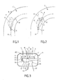
- Fig. 1 we can see a vehicle A equipped with a device classic ACC driving aid whose transmitter sends forward the conveys a beam F whose axis is fixed relative to the vehicle A, parallel to the longitudinal axis X-X of this vehicle.
- F ' the outline of the code lighting beam.
- a target vehicle is represented by B.
- vehicle B Before entering a turn C, vehicle B was detected by the beam F of the following vehicle A. By taking its turn, the target vehicle B leaves the beam F and the follower vehicle A loses track of target vehicle B, with the consequences outlined above.
- Fig. 2 shows the follower vehicle A fitted with an assistance device to the ACC pipe according to the invention.
- the azimuth of the beam F of the transmitter i.e. the angle ⁇ between the longitudinal axis X-X of the vehicle A and the axis Y of the beam F, is modified according to the curvature of the road of so as to follow this curvature by the beam.
- Fig. 2 we see that the beam F always reaches the target vehicle B whose trace is not not lost by the following vehicle A.
- Fig.3 is a schematic top view of a device for assisting in the ACC pipe integrated into a headlamp 1 mounted at the front of the vehicle.
- the projector 1 comprises a housing 2 provided, at the front, with a optical 3 transparent.
- the case is cut by a horizontal plane so that the interior elements are visible.
- Projector 1 is provided to provide an AFS function (Adaptive Frontlighting System). This is an optimization of lighting. In the case of Fig. 3 this lighting optimization is obtained thanks to a BL (Bending) function Light, or code turn) according to which a code 4 is rotatably mounted in azimuth to light up where the car is going and no longer just in front.
- AFS Adaptive Frontlighting System
- Code 4 is mounted on a plate 5, which is itself mounted rotating around an essentially vertical axis 6, for example located in the longitudinal median plane of the projector or in the vicinity of this plane.
- the code 4 is placed in the vicinity of an edge of the plate 5 remote from the axis 6.
- a possible route 7 spotlight can be installed in the vicinity of the other edge of plate 5.
- the headlamp may not be mounted secured to the plate of code 4 and may not even exist if code 4 is a bifunction.
- the arrows L symbolize the light beams emitted by code 4 and the headlight route 7.
- the rotational movement of the plate 5 around the axis 6 is provided by an electric motor 8, the casing of which is fixedly mounted relative to the housing 2, on the side of the plate 5 opposite the optics 3.
- the motor 8 controls (by a mechanical system not shown) displacements of a rod 9 parallel to the longitudinal axis of the vehicle as indicated by a double arrow H.
- the end of the rod 9 remote of the motor 8 is connected by an articulation to the rear face of the plate 5, away from axis 6.
- the amplitude and the direction of rotation of the motor 8 are controlled by a computer 10, constituting a set of calculation and control, connected by a cable 11 to the motor 8.
- the assembly 10 is supplied with electric power by a cable 12, and receives by a cable 13 vehicle information from various sensors (not shown). Cable 13 can provide a direct wired connection or multiplexed. Set 10 can exchange information with sensors as indicated by the double arrow along the cable 13.
- the housing of the control assembly 10 may, so undifferentiated, located inside or outside the projector 1 in one any location of the vehicle, and the vehicle may include one or two (one for both sides, or one for each side).
- the ACC driving assistance device includes a transmitter 14 mounted on the plate 5, for example in the central region of this platinum.
- the transmitter 14, of the radar or lidar type emits a beam towards the front shown diagrammatically by the arrow 15.
- the ACC device includes a receiver 16, also mounted on plate 5. Receiver 16 receives part of the beam reflected by the target vehicle, as shown by arrow 17.
- connection of the ACC device to the control assembly 10 is provided by a multi-wire bundle 18 allowing supply and exchange of information.
- the projector 1 in Fig.3 is of the "MBL" type (Main Bending Light / rotating code) according to which code 4 rotates around the axis vertical 6, following the direction of curvature of the road, in order to properly illuminate the curved edge of the road.
- MBL Main Bending Light / rotating code
- the last three sources of information allow anticipation of the vehicle trajectory and therefore of the performance of the driver assistance device, the first two sources only describe than the configuration under the vehicle.
- the control unit 10 When the driver activates the ACC assistance device, the control unit 10 is supplied and put into service, even if the vehicle is running in broad daylight when code 4 is off.
- the engine 8 is controlled by the assembly 10 and the plate 5 will rotate around the axis vertical 6 according to the information received on the road profile.
- the beam F of the transmitter 14, i.e. the arrow 15 which represents it schematically, will be oriented at best according to the curvature of the road, which improves the tracking of target vehicle B.
- the improvement of operation of the ACC device does not require a motorization additional costly angular nor an additional interpretation of vehicle data.
- the integration of the ACC device in the projector 1 allows it to benefit from its protections (headlamp washer, waterproofing) against rain and dirt, which is particularly important in the case of an ACC device with lidar whose emission and reception in the infrared range are particularly affected by a reduction of transparency of the optics 3.
- attitude correction to which corresponds a rotation of the plate 5 around a horizontal transverse axis (not shown).
- the device ACC will then benefit from this attitude correction allowing a simplification of vertical scanning of targets.
- Fig. 4 shows an alternative embodiment in which the ACC device is integrated in a projector 1a of the ABL type, that is to say additional rotating projector.
- the lighting is optimized using the projector additional 1a installed in the bumper or bumper of the vehicle.
- the housing 2a of the projector 1a comprises a plate 5a rotatably mounted around a vertical axis 6a.
- a light projector 4a On the front of the plate is installed a light projector 4a whose azimuth is modified by the rotation of the platinum 5a.
- This rotation is controlled by the motor 8 including the casing is mounted fixed in the housing 2a.
- the motor 8 is connected by the cable 11 to the control assembly 10 which is located in the housing 2 of the projector 1.
- the ACC assistance device is fixed on the plate 5a, in front, on the side of the axis 6a opposite to the projector 4a. Cable 18 connects the transmitter assembly 14 - receiver 16 of the ACC device to the control unit 10.
- the assembly 10 controls the rotation of the plate 5a around the vertical axis 6a in based on road curvature information.
- the ACC system is properly oriented for better tracking of the target vehicle B.
- a daylight, the projector 4a remains off and the rotation of the plate Its is only used by the ACC system.
- the rotation of the plate Sa ensures both optimizing lighting and tracking the target vehicle.
- control assembly 10 in the housing 2 of the projector 1 is not limiting.
- This set of command 10 can be found either in the shield or in the engine compartment or any other advantageous place in the vehicle.
- the additional headlight 1a may also include fog lights.
- the style or exterior appearance of the vehicle can be homogenized by installing in the additional projector located on the other side of the conveys an inert element of the same appearance as the ACC device.
- Fig. 5 shows an alternative embodiment according to which the ACC device is mechanically separated from projector 1 of the type MBL of Fig. 3, whose identical elements are designated by the same digital references.
- the transmitter 14 and the receiver 16 of the ACC device are fixed to the front of a plate 5b rotatably mounted around a vertical axis 6b in a housing 2b specific to the ACC device.
- the housing 2b is arranged, by example, in the middle at the front of the vehicle, in front of the radiator.
- a motor 8b the housing of which is fixed relative to the housing 2b, is placed behind the plate 5b, on one side thereof.
- the motor 8b controls the rectilinear displacement of a rod 9b substantially perpendicular to the platinum 5b.
- One end of the rod 9b is articulated to the plate.
- the displacement of the rod 9b causes the rotation of the plate 5b around axis 6b.
- the front face of the housing 2b is constituted by a wall 3b transparent to the radiation from the transmitter 14.
- the engine control 8b is provided by the assembly 10 connected to this motor by a cable 11b.
- the azimuth of the plate 5b of the transmitter 14 can thus be modified or following the same angle instructions as for plate 5 of projector 1, or alternatively in proportion to these.
- Fig. 6 shows an alternative embodiment which does not differ from that Fig.5 that by installing the ACC device in the same housing 1, enlarged, than the main projector rotating. But the ACC system remains installed on a rotary plate 5b different from the projector plate 5 turning.
- the same reference numbers are used to designate elements identical to those of Fig. 5.
- Fig. 7 shows an alternative embodiment according to which each vehicle headlight 1 is equipped with a headlight fixed turn 19 (designated by the acronym FBL), pre-turned outwards.
- the projector 1 is the one located on the left of the vehicle, the headlight 19 being pre-turned to the left.
- food electric projector 19 is provided by a cable 20 connected to the assembly 10.
- the dimming or the light intensity of the projector 19 is adjusted according to the road and vehicle parameters, collected by the set 10.
- the azimuth of the plate 5 is not changed in based on these parameters.
- the ACC device with its transmitter 14 and its receiver 17 is mounted, as in Fig.4, in a separate housing 2a, on a plate rotary 5a whose orientation around the vertical axis 6a is controlled by the assembly 10 as a function of the parameters of the road and of the vehicle.
- Fig.8 shows an alternative embodiment of the device of Fig.6, the similar elements being designated by the same references digital.
- Two different plates 5, 5b are provided to support respectively the light projectors 4, 7, and the emitter assembly 14 - receiver 16 of the ACC device.
- the plates 5, 5b are mounted to rotate around respective vertical axes 6, 6b.
- the rotational drive of the plate 5b around the axis 6b is provided by a mechanism 21 for transmitting the movement of rotation of the plate 5.
- the mechanism 21 shown diagrammatically in FIG. 8 is of the deformable parallelogram type comprising two rods 22, 23 parallel, fixed in rotation respectively on the plates 5, 5b and a connecting rod 24 articulated at each end of the rods 22, 23 distant from axes 6, 6b. Any other transmission mechanism allowing the same plate 5b to rotate, or proportional to that of plate 5 will be suitable.
- the ACC device will follow the outline of the road by the same so that the projectors 4, 7 installed on the movable plate 5 ensuring the BL function.
- Fig. 9 shows an alternative embodiment according to which the ACC assist device receiver 16 is fixed relative to the chassis of the vehicle and arranged, for example, in a housing 25 located at the front, at middle of the vehicle.
- the transmitter 14 is rotatably mounted around an axis vertical so as to follow the curvature of the road.
- the transmitter 14 is mounted on the plate 5 of a type projector MBL, such as that shown in Fig. 3.
- Deck 5 has the code 4 and the possible headlamp 7. We find the engine 8 controlling the turntable rotation 5.
- the lighting optimization system controls the rotation in the horizontal plane of the projectors as well inwards of the turn only outwards, a single transmitter 14 for the device VAC help is required. It can be mounted on the plate 5 of the right projector 1d or of the left projector 1g. This consideration is valid for all cases declined.
- the lighting optimization system is designed to turn only the headlamp located inside the bend, we plan to then, for the ACC assistance device, a transmitter 14 on each plate 5 right headlights 1d and left headlights 1g.
- the receiver 16 is connected by two cables 26d, 26g respectively to the control assemblies 10 of the left headlight and right projector.
- the operation is the same as that explained previously, the transmitter 14 being oriented along the curvature of the road.
- each of the projectors can rotate outward to provide BL function and is equipped with an ACC assistance device.
- Figs. 3 to 8 then represent the right side as the left side. The set is provided so that the active side (side of the projector which is turning) inhibits the ACC device on the other side because only one ACC device is used at the time. It is then necessary to connect the information wires as in Fig. 9.
- the invention allows, by interposing in the ACC aid device a rotating mechanism, deflect the emitted beam, radar or lidar, depending on the information on the curvature of the road, and improve tracking of target vehicle B.
- Rotary mounting of the ACC device can be provided even if the vehicle is not equipped with a lighting optimization system taking into account the curvature of the road.
Landscapes
- Engineering & Computer Science (AREA)
- Radar, Positioning & Navigation (AREA)
- Remote Sensing (AREA)
- Physics & Mathematics (AREA)
- Computer Networks & Wireless Communication (AREA)
- General Physics & Mathematics (AREA)
- Mechanical Engineering (AREA)
- Electromagnetism (AREA)
- Automation & Control Theory (AREA)
- Transportation (AREA)
- Lighting Device Outwards From Vehicle And Optical Signal (AREA)
- Controls For Constant Speed Travelling (AREA)
- Traffic Control Systems (AREA)
- Control Of Stepping Motors (AREA)
- Automatic Cycles, And Cycles In General (AREA)
- Auxiliary Drives, Propulsion Controls, And Safety Devices (AREA)
- Control Of Multiple Motors (AREA)
- Control Of Eletrric Generators (AREA)
- Electric Propulsion And Braking For Vehicles (AREA)
Applications Claiming Priority (2)
| Application Number | Priority Date | Filing Date | Title |
|---|---|---|---|
| FR0116505 | 2001-12-20 | ||
| FR0116505A FR2834110B1 (fr) | 2001-12-20 | 2001-12-20 | Dispositif d'aide a la conduite pour vehicule automobile optimise par synergie avec un eclairage adaptatif |
Publications (2)
| Publication Number | Publication Date |
|---|---|
| EP1323570A1 true EP1323570A1 (de) | 2003-07-02 |
| EP1323570B1 EP1323570B1 (de) | 2005-06-08 |
Family
ID=8870715
Family Applications (1)
| Application Number | Title | Priority Date | Filing Date |
|---|---|---|---|
| EP02292862A Expired - Lifetime EP1323570B1 (de) | 2001-12-20 | 2002-11-18 | Hilfsvorrichtung zur Steuerung eines Kraftfahrzeuges |
Country Status (7)
| Country | Link |
|---|---|
| US (1) | US6828928B2 (de) |
| EP (1) | EP1323570B1 (de) |
| JP (1) | JP2004046783A (de) |
| AT (1) | ATE297323T1 (de) |
| DE (1) | DE60204534T2 (de) |
| ES (1) | ES2243673T3 (de) |
| FR (1) | FR2834110B1 (de) |
Cited By (12)
| Publication number | Priority date | Publication date | Assignee | Title |
|---|---|---|---|---|
| GB2390440A (en) * | 2002-05-21 | 2004-01-07 | Visteon Global Tech Inc | Target vehicle identification based on the theoretical relationship between the azimuth angle and relative velocity |
| GB2395548B (en) * | 2002-11-14 | 2005-02-02 | Visteon Global Tech Inc | Adaptive frontlighting system for motor vehicles |
| FR2892693A1 (fr) * | 2005-10-28 | 2007-05-04 | Valeo Systemes Thermiques | Face avant perfectionnee pour vehicule automobile |
| DE102006006850A1 (de) * | 2006-02-15 | 2007-08-30 | Bayerische Motoren Werke Ag | Verfahren zur Ausrichtung eines verschwenkbaren Fahrzeugsensors |
| WO2008046523A1 (de) * | 2006-10-19 | 2008-04-24 | Bayerische Motoren Werke Aktiengesellschaft | Kraftfahrzeugscheinwerfer |
| WO2008074392A2 (de) | 2006-12-16 | 2008-06-26 | Bayerische Motoren Werke Aktiengesellschaft | Kraftfahrzeugscheinwerfer |
| EP2042389A1 (de) * | 2007-09-28 | 2009-04-01 | Valeo Vision | Schutzsystem für Fußgänger im Fall eines Zusammenstoßes mit einem Fahrzeug |
| EP1666304A3 (de) * | 2004-12-03 | 2010-07-14 | Hella KG Hueck & Co. | Scheinwerfer für Fahrzeuge |
| WO2014180856A1 (de) * | 2013-05-06 | 2014-11-13 | Bluetechnix Group Gmbh | Fahrzeugscheinwerfer |
| CN104684782A (zh) * | 2012-10-04 | 2015-06-03 | 罗伯特·博世有限公司 | 对目标物体转弯作出反应的acc |
| CN111679662A (zh) * | 2019-02-25 | 2020-09-18 | 北汽福田汽车股份有限公司 | 一种车辆的控制方法及装置、存储介质和处理器 |
| EP3892916A4 (de) * | 2018-12-06 | 2022-08-10 | Kyocera Corporation | Kraftfahrzeuglampenfassung und fahrzeug |
Families Citing this family (22)
| Publication number | Priority date | Publication date | Assignee | Title |
|---|---|---|---|---|
| DE102004004492A1 (de) * | 2004-01-29 | 2005-08-18 | Robert Bosch Gmbh | Radarsystem für Kraftfahrzeuge |
| JP2006201013A (ja) * | 2005-01-20 | 2006-08-03 | Hitachi Ltd | 車載用レーダ |
| US20070052555A1 (en) * | 2005-09-08 | 2007-03-08 | Visteon Global Technologies, Inc. | Predictive adaptive front lighting integrated system |
| TWI269727B (en) * | 2006-01-09 | 2007-01-01 | Ind Tech Res Inst | Method and apparatus of assistant monitor for vehicle |
| JP4545132B2 (ja) * | 2006-10-10 | 2010-09-15 | 三菱電機株式会社 | 車載用レーダシステム |
| JP2008146933A (ja) * | 2006-12-07 | 2008-06-26 | Koito Mfg Co Ltd | 車両用灯具 |
| DE102007062566A1 (de) * | 2007-12-22 | 2009-07-02 | Audi Ag | Kraftfahrzeug |
| DE102012111716A1 (de) * | 2012-12-03 | 2014-06-05 | Trw Automotive Electronics & Components Gmbh | Strahlungserfassungseinrichtung |
| US9274222B1 (en) * | 2013-03-04 | 2016-03-01 | Toyota Motor Engineering & Manufacturing North America, Inc. | Dynamic allocation of radar beams in automotive environments with phased array radar |
| KR101993153B1 (ko) | 2014-02-27 | 2019-06-26 | 주식회사 만도 | 차량용 레이더의 자동 수직 보정 장치 및 방법 |
| KR102214332B1 (ko) * | 2014-04-30 | 2021-02-10 | 주식회사 만도 | 운전자 편의 시스템 및 운전자 편의 시스템에서 레이더 센서의 수직각도 이상 판정 방법 |
| US9260148B1 (en) * | 2014-11-24 | 2016-02-16 | Wen-Sung Lee | Light unit for bicycle/motorbike |
| JP6447305B2 (ja) * | 2015-03-30 | 2019-01-09 | トヨタ自動車株式会社 | 車両用周辺情報検出構造 |
| KR101647629B1 (ko) * | 2015-04-29 | 2016-08-11 | 김원희 | 보행 보조 장비 |
| DE102016210718A1 (de) * | 2016-06-16 | 2017-12-21 | Bayerische Motoren Werke Aktiengesellschaft | Kraftfahrzeug |
| CN106043277B (zh) * | 2016-06-30 | 2019-06-28 | 大连楼兰科技股份有限公司 | 汽车自动跟车控制系统及方法、汽车自动跟车系统及方法,控制雷达转向方法 |
| CN109690244B (zh) * | 2016-09-15 | 2021-09-17 | 株式会社小糸制作所 | 传感器系统、传感器模块及灯装置 |
| DE102017210045A1 (de) * | 2017-06-14 | 2018-12-20 | Robert Bosch Gmbh | Sensorvorrichtung für ein automatisiertes Fahrzeug |
| CN107195176A (zh) * | 2017-07-07 | 2017-09-22 | 北京汽车集团有限公司 | 用于车队的控制方法和装置 |
| WO2019106664A1 (en) | 2017-11-28 | 2019-06-06 | Israel Aerospace Industries Ltd. | Failure detection in an autonomous vehicle |
| JP7187291B2 (ja) * | 2018-12-14 | 2022-12-12 | 株式会社小糸製作所 | 赤外線カメラシステム及び車両 |
| US11643005B2 (en) * | 2019-02-27 | 2023-05-09 | Autobrains Technologies Ltd | Adjusting adjustable headlights of a vehicle |
Citations (4)
| Publication number | Priority date | Publication date | Assignee | Title |
|---|---|---|---|---|
| US5266955A (en) * | 1991-07-08 | 1993-11-30 | Kansei Corporation | Laser-radar type distance measuring equipment |
| EP1034963A1 (de) * | 1997-12-01 | 2000-09-13 | Hitachi, Ltd. | Fahrgeschwindigkeitsregler für automobile |
| US6294986B1 (en) * | 1997-08-25 | 2001-09-25 | Mannesmann Vdo Ag | Method and system for determining a regulator object |
| DE10018556A1 (de) * | 2000-04-14 | 2001-10-18 | Bosch Gmbh Robert | Verfahren zur Regelung der Geschwindigkeit eines Fahrzeugs |
Family Cites Families (20)
| Publication number | Priority date | Publication date | Assignee | Title |
|---|---|---|---|---|
| JPH0771908B2 (ja) * | 1989-05-11 | 1995-08-02 | 日産自動車株式会社 | 車両用ランプ装置 |
| JPH0527037A (ja) * | 1991-06-25 | 1993-02-05 | Kansei Corp | 車間距離測定レーダ |
| JPH0511051A (ja) * | 1991-07-08 | 1993-01-19 | Kansei Corp | 車間距離測定レーダ |
| JP3589742B2 (ja) * | 1995-05-25 | 2004-11-17 | 富士通テン株式会社 | 車載用レーダ装置 |
| JP3209671B2 (ja) * | 1995-11-27 | 2001-09-17 | 富士通テン株式会社 | カーブ路判定装置 |
| US6611610B1 (en) * | 1997-04-02 | 2003-08-26 | Gentex Corporation | Vehicle lamp control |
| JPH1116099A (ja) * | 1997-06-27 | 1999-01-22 | Hitachi Ltd | 自動車走行支援装置 |
| JP3414267B2 (ja) * | 1997-07-22 | 2003-06-09 | 株式会社デンソー | 車両用障害物検出装置の中心軸偏向量算出装置、中心軸偏向量補正装置および車間距離制御装置 |
| JP2001287587A (ja) * | 2000-04-04 | 2001-10-16 | Nissan Motor Co Ltd | 車両用照明装置 |
| JP2001341577A (ja) * | 2000-05-31 | 2001-12-11 | Mitsubishi Electric Corp | 車両用前照灯システム、及び車両用前照灯の照射軸調整装置 |
| JP3865574B2 (ja) * | 2000-08-09 | 2007-01-10 | 株式会社小糸製作所 | 車両用前照灯システム |
| JP3753932B2 (ja) * | 2000-08-09 | 2006-03-08 | 株式会社小糸製作所 | 車両用前照灯システム |
| JP2002104065A (ja) * | 2000-09-28 | 2002-04-09 | Denso Corp | 車両用前照灯光軸方向自動調整装置 |
| JP3986759B2 (ja) * | 2001-01-16 | 2007-10-03 | 株式会社小糸製作所 | 車両用前照灯 |
| US6652130B2 (en) * | 2001-01-25 | 2003-11-25 | Koito Manufacturing Co., Ltd. | Vehicle headlamp |
| JP4002077B2 (ja) * | 2001-04-26 | 2007-10-31 | 株式会社小糸製作所 | 自動車用前照灯 |
| JP2002326534A (ja) * | 2001-05-07 | 2002-11-12 | Koito Mfg Co Ltd | 車両用照明装置 |
| JP3926615B2 (ja) * | 2001-12-11 | 2007-06-06 | 本田技研工業株式会社 | 灯体制御装置 |
| DE10210874B4 (de) * | 2002-03-12 | 2008-09-11 | Automotive Lighting Reutlingen Gmbh | Scheinwerfer |
| JP3999008B2 (ja) * | 2002-03-15 | 2007-10-31 | 株式会社小糸製作所 | 車両用灯具 |
-
2001
- 2001-12-20 FR FR0116505A patent/FR2834110B1/fr not_active Expired - Fee Related
-
2002
- 2002-11-18 DE DE60204534T patent/DE60204534T2/de not_active Expired - Lifetime
- 2002-11-18 ES ES02292862T patent/ES2243673T3/es not_active Expired - Lifetime
- 2002-11-18 AT AT02292862T patent/ATE297323T1/de not_active IP Right Cessation
- 2002-11-18 EP EP02292862A patent/EP1323570B1/de not_active Expired - Lifetime
- 2002-12-13 US US10/318,724 patent/US6828928B2/en not_active Expired - Lifetime
- 2002-12-17 JP JP2002365208A patent/JP2004046783A/ja active Pending
Patent Citations (4)
| Publication number | Priority date | Publication date | Assignee | Title |
|---|---|---|---|---|
| US5266955A (en) * | 1991-07-08 | 1993-11-30 | Kansei Corporation | Laser-radar type distance measuring equipment |
| US6294986B1 (en) * | 1997-08-25 | 2001-09-25 | Mannesmann Vdo Ag | Method and system for determining a regulator object |
| EP1034963A1 (de) * | 1997-12-01 | 2000-09-13 | Hitachi, Ltd. | Fahrgeschwindigkeitsregler für automobile |
| DE10018556A1 (de) * | 2000-04-14 | 2001-10-18 | Bosch Gmbh Robert | Verfahren zur Regelung der Geschwindigkeit eines Fahrzeugs |
Cited By (22)
| Publication number | Priority date | Publication date | Assignee | Title |
|---|---|---|---|---|
| GB2390440B (en) * | 2002-05-21 | 2004-06-09 | Visteon Global Tech Inc | Target vehicle identification based on the theoretical relationship between the azimuth angle and relative velocity |
| US6753804B2 (en) | 2002-05-21 | 2004-06-22 | Visteon Global Technologies, Inc. | Target vehicle identification based on the theoretical relationship between the azimuth angle and relative velocity |
| GB2390440A (en) * | 2002-05-21 | 2004-01-07 | Visteon Global Tech Inc | Target vehicle identification based on the theoretical relationship between the azimuth angle and relative velocity |
| GB2395548B (en) * | 2002-11-14 | 2005-02-02 | Visteon Global Tech Inc | Adaptive frontlighting system for motor vehicles |
| EP1666304A3 (de) * | 2004-12-03 | 2010-07-14 | Hella KG Hueck & Co. | Scheinwerfer für Fahrzeuge |
| FR2892693A1 (fr) * | 2005-10-28 | 2007-05-04 | Valeo Systemes Thermiques | Face avant perfectionnee pour vehicule automobile |
| DE102006006850A1 (de) * | 2006-02-15 | 2007-08-30 | Bayerische Motoren Werke Ag | Verfahren zur Ausrichtung eines verschwenkbaren Fahrzeugsensors |
| US8798927B2 (en) | 2006-02-15 | 2014-08-05 | Bayerische Motoren Werke Aktiengesellschaft | Method of aligning a swivelable vehicle sensor |
| WO2008046523A1 (de) * | 2006-10-19 | 2008-04-24 | Bayerische Motoren Werke Aktiengesellschaft | Kraftfahrzeugscheinwerfer |
| US7896533B2 (en) | 2006-10-19 | 2011-03-01 | Bayerische Motoren Werke Aktiengesellschaft | Motor vehicle headlight |
| WO2008074392A2 (de) | 2006-12-16 | 2008-06-26 | Bayerische Motoren Werke Aktiengesellschaft | Kraftfahrzeugscheinwerfer |
| WO2008074392A3 (de) * | 2006-12-16 | 2008-09-18 | Bayerische Motoren Werke Ag | Kraftfahrzeugscheinwerfer |
| EP2042389A1 (de) * | 2007-09-28 | 2009-04-01 | Valeo Vision | Schutzsystem für Fußgänger im Fall eines Zusammenstoßes mit einem Fahrzeug |
| CN104684782B (zh) * | 2012-10-04 | 2017-07-28 | 罗伯特·博世有限公司 | 用于车辆的自适应巡航控制系统及方法 |
| CN104684782A (zh) * | 2012-10-04 | 2015-06-03 | 罗伯特·博世有限公司 | 对目标物体转弯作出反应的acc |
| CN105492252A (zh) * | 2013-05-06 | 2016-04-13 | 蓝泰科尼克集团有限公司 | 车辆大灯 |
| WO2014180856A1 (de) * | 2013-05-06 | 2014-11-13 | Bluetechnix Group Gmbh | Fahrzeugscheinwerfer |
| US9802527B2 (en) | 2013-05-06 | 2017-10-31 | Bluetechnix Group Gmbh | Vehicle headlight |
| EP3892916A4 (de) * | 2018-12-06 | 2022-08-10 | Kyocera Corporation | Kraftfahrzeuglampenfassung und fahrzeug |
| US11530794B2 (en) | 2018-12-06 | 2022-12-20 | Kyocera Corporation | Lighting device for a vehicle and vehicle |
| CN111679662A (zh) * | 2019-02-25 | 2020-09-18 | 北汽福田汽车股份有限公司 | 一种车辆的控制方法及装置、存储介质和处理器 |
| CN111679662B (zh) * | 2019-02-25 | 2022-07-15 | 北汽福田汽车股份有限公司 | 一种车辆的控制方法及装置、存储介质和处理器 |
Also Published As
| Publication number | Publication date |
|---|---|
| US20030122704A1 (en) | 2003-07-03 |
| ATE297323T1 (de) | 2005-06-15 |
| JP2004046783A (ja) | 2004-02-12 |
| DE60204534D1 (de) | 2005-07-14 |
| EP1323570B1 (de) | 2005-06-08 |
| DE60204534T2 (de) | 2006-03-16 |
| FR2834110B1 (fr) | 2004-01-30 |
| FR2834110A1 (fr) | 2003-06-27 |
| ES2243673T3 (es) | 2005-12-01 |
| US6828928B2 (en) | 2004-12-07 |
Similar Documents
| Publication | Publication Date | Title |
|---|---|---|
| EP1323570B1 (de) | Hilfsvorrichtung zur Steuerung eines Kraftfahrzeuges | |
| EP3045806B1 (de) | Optisches modul für ein kraftfahrzeug, das selektiv eine zone beleuchten kann | |
| FR2808750A1 (fr) | Phare de vehicule, et procede de reglage lateral de son faisceau | |
| EP2957464B1 (de) | Drehbares beleuchtungs- und/oder signalisierungsmodul | |
| FR2833547A1 (fr) | Phare de vehicule a correction de panne du faisceau de croisement | |
| FR2811276A1 (fr) | Systeme de phares pour vehicules et procede pour leur commande | |
| FR2929193A1 (fr) | Dispositif d'eclairement a orientation variable de l'environnement d'un vehicule automobile | |
| FR2660262A1 (fr) | Systeme d'eclairage et de visualisation pour vehicules. | |
| EP2301801A1 (de) | Verfahren zur Steuerung eines Fahrzeugscheinwerfers | |
| EP1502814B2 (de) | Scheinwerfer für Abblend- und Kurvenlicht für Kraftfahrzeuge | |
| EP2957823A1 (de) | Drehbares beleuchtungs- und/oder signalisierungsmodul | |
| EP2988972B1 (de) | Verfahren zur steuerung eines regulierbaren beleuchtungssystems für ein trägerfahrzeug und reguliebares beleuchtungsystem | |
| EP3707429B1 (de) | Beleuchtungsgerät mit einem hauptstrahl und einem schmalen nebenstrahl, der von einem zusammenbau generiert wird, der in abhängigkeit der position eines detektierten hindernisses im vorfeld eines fahrzeugs orientierbar ist | |
| FR2815394A1 (fr) | Phare pour vehicule a une seule source lumineuse et plusieurs diagrammes d'eclairage | |
| EP1619440B1 (de) | Beleuchtungssystem für Kraftfahrzeuge mit Überlappung von Lichtbündeln | |
| FR2797614A1 (fr) | Dispositif d'eclairage et/ou signalisation pour vehicule et systeme d'eclairage de vehicule comportant un tel dispositif | |
| EP2168812B1 (de) | Beleuchtungssystem für ein kraftfahrzeug, das die emission eines abblendlichts verändern kann | |
| EP3455102B1 (de) | Beleuchtungssystem und verfahren für ein kraftfahrzeug | |
| FR2941188A1 (fr) | Retroviseur exterieur de vehicule notamment automobile a moyen d'eclairage integre | |
| FR3044387A1 (fr) | Dispositif lumineux pour vehicule | |
| FR3094300A1 (fr) | Véhicule comprenant un ensemble déflecteur d’air et un dispositif lumineux | |
| FR2818210A1 (fr) | Projecteur tournant pour vehicule automobile comportant une lampe a deux sources | |
| KR880000687B1 (ko) | 헤드라이트의 광선 조절 장치 | |
| FR3116103A1 (fr) | Dispositif d’éclairage adaptatif comportant un module tournant, et véhicule ainsi équipé. | |
| WO2021094544A1 (fr) | Module d'eclairage pour partie laterale d'un vehicule |
Legal Events
| Date | Code | Title | Description |
|---|---|---|---|
| PUAI | Public reference made under article 153(3) epc to a published international application that has entered the european phase |
Free format text: ORIGINAL CODE: 0009012 |
|
| AK | Designated contracting states |
Designated state(s): AT BE BG CH CY CZ DE DK EE ES FI FR GB GR IE IT LI LU MC NL PT SE SK TR |
|
| AX | Request for extension of the european patent |
Extension state: AL LT LV MK RO SI |
|
| 17P | Request for examination filed |
Effective date: 20030718 |
|
| AKX | Designation fees paid |
Designated state(s): AT BE BG CH CY CZ DE DK EE ES FI FR GB GR IE IT LI LU MC NL PT SE SK TR |
|
| 17Q | First examination report despatched |
Effective date: 20040423 |
|
| GRAP | Despatch of communication of intention to grant a patent |
Free format text: ORIGINAL CODE: EPIDOSNIGR1 |
|
| RIC1 | Information provided on ipc code assigned before grant |
Ipc: 7G 01S 17/02 B Ipc: 7B 60K 31/00 A Ipc: 7G 01S 17/93 B Ipc: 7G 01S 7/481 B |
|
| GRAS | Grant fee paid |
Free format text: ORIGINAL CODE: EPIDOSNIGR3 |
|
| GRAA | (expected) grant |
Free format text: ORIGINAL CODE: 0009210 |
|
| AK | Designated contracting states |
Kind code of ref document: B1 Designated state(s): AT BE BG CH CY CZ DE DK EE ES FI FR GB GR IE IT LI LU MC NL PT SE SK TR |
|
| PG25 | Lapsed in a contracting state [announced via postgrant information from national office to epo] |
Ref country code: FI Free format text: LAPSE BECAUSE OF FAILURE TO SUBMIT A TRANSLATION OF THE DESCRIPTION OR TO PAY THE FEE WITHIN THE PRESCRIBED TIME-LIMIT Effective date: 20050608 Ref country code: TR Free format text: LAPSE BECAUSE OF FAILURE TO SUBMIT A TRANSLATION OF THE DESCRIPTION OR TO PAY THE FEE WITHIN THE PRESCRIBED TIME-LIMIT Effective date: 20050608 Ref country code: IE Free format text: LAPSE BECAUSE OF FAILURE TO SUBMIT A TRANSLATION OF THE DESCRIPTION OR TO PAY THE FEE WITHIN THE PRESCRIBED TIME-LIMIT Effective date: 20050608 Ref country code: NL Free format text: LAPSE BECAUSE OF FAILURE TO SUBMIT A TRANSLATION OF THE DESCRIPTION OR TO PAY THE FEE WITHIN THE PRESCRIBED TIME-LIMIT Effective date: 20050608 Ref country code: EE Free format text: LAPSE BECAUSE OF FAILURE TO SUBMIT A TRANSLATION OF THE DESCRIPTION OR TO PAY THE FEE WITHIN THE PRESCRIBED TIME-LIMIT Effective date: 20050608 Ref country code: CZ Free format text: LAPSE BECAUSE OF FAILURE TO SUBMIT A TRANSLATION OF THE DESCRIPTION OR TO PAY THE FEE WITHIN THE PRESCRIBED TIME-LIMIT Effective date: 20050608 Ref country code: SK Free format text: LAPSE BECAUSE OF FAILURE TO SUBMIT A TRANSLATION OF THE DESCRIPTION OR TO PAY THE FEE WITHIN THE PRESCRIBED TIME-LIMIT Effective date: 20050608 Ref country code: AT Free format text: LAPSE BECAUSE OF FAILURE TO SUBMIT A TRANSLATION OF THE DESCRIPTION OR TO PAY THE FEE WITHIN THE PRESCRIBED TIME-LIMIT Effective date: 20050608 |
|
| REG | Reference to a national code |
Ref country code: GB Ref legal event code: FG4D Free format text: NOT ENGLISH |
|
| REG | Reference to a national code |
Ref country code: CH Ref legal event code: EP |
|
| REF | Corresponds to: |
Ref document number: 60204534 Country of ref document: DE Date of ref document: 20050714 Kind code of ref document: P |
|
| REG | Reference to a national code |
Ref country code: IE Ref legal event code: FG4D Free format text: LANGUAGE OF EP DOCUMENT: FRENCH |
|
| PG25 | Lapsed in a contracting state [announced via postgrant information from national office to epo] |
Ref country code: BG Free format text: LAPSE BECAUSE OF FAILURE TO SUBMIT A TRANSLATION OF THE DESCRIPTION OR TO PAY THE FEE WITHIN THE PRESCRIBED TIME-LIMIT Effective date: 20050908 Ref country code: GR Free format text: LAPSE BECAUSE OF FAILURE TO SUBMIT A TRANSLATION OF THE DESCRIPTION OR TO PAY THE FEE WITHIN THE PRESCRIBED TIME-LIMIT Effective date: 20050908 Ref country code: SE Free format text: LAPSE BECAUSE OF FAILURE TO SUBMIT A TRANSLATION OF THE DESCRIPTION OR TO PAY THE FEE WITHIN THE PRESCRIBED TIME-LIMIT Effective date: 20050908 Ref country code: DK Free format text: LAPSE BECAUSE OF FAILURE TO SUBMIT A TRANSLATION OF THE DESCRIPTION OR TO PAY THE FEE WITHIN THE PRESCRIBED TIME-LIMIT Effective date: 20050908 |
|
| GBT | Gb: translation of ep patent filed (gb section 77(6)(a)/1977) |
Effective date: 20050908 |
|
| PG25 | Lapsed in a contracting state [announced via postgrant information from national office to epo] |
Ref country code: PT Free format text: LAPSE BECAUSE OF FAILURE TO SUBMIT A TRANSLATION OF THE DESCRIPTION OR TO PAY THE FEE WITHIN THE PRESCRIBED TIME-LIMIT Effective date: 20051114 |
|
| PG25 | Lapsed in a contracting state [announced via postgrant information from national office to epo] |
Ref country code: CY Free format text: LAPSE BECAUSE OF FAILURE TO SUBMIT A TRANSLATION OF THE DESCRIPTION OR TO PAY THE FEE WITHIN THE PRESCRIBED TIME-LIMIT Effective date: 20051118 |
|
| PG25 | Lapsed in a contracting state [announced via postgrant information from national office to epo] |
Ref country code: BE Free format text: LAPSE BECAUSE OF NON-PAYMENT OF DUE FEES Effective date: 20051130 Ref country code: MC Free format text: LAPSE BECAUSE OF NON-PAYMENT OF DUE FEES Effective date: 20051130 Ref country code: LU Free format text: LAPSE BECAUSE OF NON-PAYMENT OF DUE FEES Effective date: 20051130 |
|
| NLV1 | Nl: lapsed or annulled due to failure to fulfill the requirements of art. 29p and 29m of the patents act | ||
| REG | Reference to a national code |
Ref country code: ES Ref legal event code: FG2A Ref document number: 2243673 Country of ref document: ES Kind code of ref document: T3 |
|
| REG | Reference to a national code |
Ref country code: IE Ref legal event code: FD4D |
|
| PLBE | No opposition filed within time limit |
Free format text: ORIGINAL CODE: 0009261 |
|
| STAA | Information on the status of an ep patent application or granted ep patent |
Free format text: STATUS: NO OPPOSITION FILED WITHIN TIME LIMIT |
|
| 26N | No opposition filed |
Effective date: 20060309 |
|
| PG25 | Lapsed in a contracting state [announced via postgrant information from national office to epo] |
Ref country code: FR Free format text: LAPSE BECAUSE OF NON-PAYMENT OF DUE FEES Effective date: 20060731 |
|
| REG | Reference to a national code |
Ref country code: FR Ref legal event code: ST Effective date: 20060731 |
|
| PG25 | Lapsed in a contracting state [announced via postgrant information from national office to epo] |
Ref country code: CH Free format text: LAPSE BECAUSE OF NON-PAYMENT OF DUE FEES Effective date: 20061130 Ref country code: LI Free format text: LAPSE BECAUSE OF NON-PAYMENT OF DUE FEES Effective date: 20061130 |
|
| REG | Reference to a national code |
Ref country code: CH Ref legal event code: PL |
|
| BERE | Be: lapsed |
Owner name: VALEO VISION Effective date: 20051130 |
|
| PGFP | Annual fee paid to national office [announced via postgrant information from national office to epo] |
Ref country code: DE Payment date: 20161115 Year of fee payment: 15 Ref country code: GB Payment date: 20161121 Year of fee payment: 15 |
|
| PGFP | Annual fee paid to national office [announced via postgrant information from national office to epo] |
Ref country code: IT Payment date: 20161116 Year of fee payment: 15 Ref country code: ES Payment date: 20161130 Year of fee payment: 15 |
|
| REG | Reference to a national code |
Ref country code: DE Ref legal event code: R119 Ref document number: 60204534 Country of ref document: DE |
|
| GBPC | Gb: european patent ceased through non-payment of renewal fee |
Effective date: 20171118 |
|
| PG25 | Lapsed in a contracting state [announced via postgrant information from national office to epo] |
Ref country code: DE Free format text: LAPSE BECAUSE OF NON-PAYMENT OF DUE FEES Effective date: 20180602 Ref country code: IT Free format text: LAPSE BECAUSE OF NON-PAYMENT OF DUE FEES Effective date: 20171118 |
|
| PG25 | Lapsed in a contracting state [announced via postgrant information from national office to epo] |
Ref country code: GB Free format text: LAPSE BECAUSE OF NON-PAYMENT OF DUE FEES Effective date: 20171118 |
|
| REG | Reference to a national code |
Ref country code: ES Ref legal event code: FD2A Effective date: 20181226 |
|
| PG25 | Lapsed in a contracting state [announced via postgrant information from national office to epo] |
Ref country code: ES Free format text: LAPSE BECAUSE OF NON-PAYMENT OF DUE FEES Effective date: 20171119 |