EP1320076A1 - Anordnung zum Schutz eines Druckmoduls in einem Postverarbeitungsgerät - Google Patents
Anordnung zum Schutz eines Druckmoduls in einem Postverarbeitungsgerät Download PDFInfo
- Publication number
- EP1320076A1 EP1320076A1 EP20020026747 EP02026747A EP1320076A1 EP 1320076 A1 EP1320076 A1 EP 1320076A1 EP 20020026747 EP20020026747 EP 20020026747 EP 02026747 A EP02026747 A EP 02026747A EP 1320076 A1 EP1320076 A1 EP 1320076A1
- Authority
- EP
- European Patent Office
- Prior art keywords
- protective cap
- arrangement according
- printing
- ribbon cable
- module
- Prior art date
- Legal status (The legal status is an assumption and is not a legal conclusion. Google has not performed a legal analysis and makes no representation as to the accuracy of the status listed.)
- Granted
Links
Images


Classifications
-
- B—PERFORMING OPERATIONS; TRANSPORTING
- B41—PRINTING; LINING MACHINES; TYPEWRITERS; STAMPS
- B41J—TYPEWRITERS; SELECTIVE PRINTING MECHANISMS, i.e. MECHANISMS PRINTING OTHERWISE THAN FROM A FORME; CORRECTION OF TYPOGRAPHICAL ERRORS
- B41J2/00—Typewriters or selective printing mechanisms characterised by the printing or marking process for which they are designed
- B41J2/005—Typewriters or selective printing mechanisms characterised by the printing or marking process for which they are designed characterised by bringing liquid or particles selectively into contact with a printing material
- B41J2/01—Ink jet
- B41J2/17—Ink jet characterised by ink handling
- B41J2/175—Ink supply systems ; Circuit parts therefor
- B41J2/17503—Ink cartridges
- B41J2/1752—Mounting within the printer
-
- B—PERFORMING OPERATIONS; TRANSPORTING
- B41—PRINTING; LINING MACHINES; TYPEWRITERS; STAMPS
- B41J—TYPEWRITERS; SELECTIVE PRINTING MECHANISMS, i.e. MECHANISMS PRINTING OTHERWISE THAN FROM A FORME; CORRECTION OF TYPOGRAPHICAL ERRORS
- B41J29/00—Details of, or accessories for, typewriters or selective printing mechanisms not otherwise provided for
- B41J29/02—Framework
-
- B—PERFORMING OPERATIONS; TRANSPORTING
- B41—PRINTING; LINING MACHINES; TYPEWRITERS; STAMPS
- B41J—TYPEWRITERS; SELECTIVE PRINTING MECHANISMS, i.e. MECHANISMS PRINTING OTHERWISE THAN FROM A FORME; CORRECTION OF TYPOGRAPHICAL ERRORS
- B41J29/00—Details of, or accessories for, typewriters or selective printing mechanisms not otherwise provided for
- B41J29/54—Locking devices applied to printing mechanisms
-
- G—PHYSICS
- G07—CHECKING-DEVICES
- G07B—TICKET-ISSUING APPARATUS; FARE-REGISTERING APPARATUS; FRANKING APPARATUS
- G07B17/00—Franking apparatus
- G07B17/00185—Details internally of apparatus in a franking system, e.g. franking machine at customer or apparatus at post office
- G07B17/00193—Constructional details of apparatus in a franking system
- G07B2017/00233—Housing, e.g. lock or hardened casing
-
- G—PHYSICS
- G07—CHECKING-DEVICES
- G07B—TICKET-ISSUING APPARATUS; FARE-REGISTERING APPARATUS; FRANKING APPARATUS
- G07B17/00—Franking apparatus
- G07B17/00459—Details relating to mailpieces in a franking system
- G07B17/00508—Printing or attaching on mailpieces
- G07B2017/00516—Details of printing apparatus
- G07B2017/00524—Printheads
- G07B2017/00532—Inkjet
Definitions
- the invention relates to an arrangement for protecting a printing module in a mail processing device according to the preamble of claim 1.
- the invention is suitable for devices with a safety housing, which inside is a security area and a non-security area have a print module in the non-security area is movably arranged and protected against unauthorized access must become. It comes especially in franking machines, Addressing machines and other mail processing devices with one Inkjet printing device for use.
- the applicant's thermal transfer franking machine T1000 has one Thermal transfer printhead fixed in the housing for printing of a franking imprint.
- the franking imprint contains one before entered and stored postal information including the Postage data to transport the letter and is in the security area created and printed inside the case.
- a on Casing on the outside of the compartment limits a non-security area and is used to hold a replaceable ribbon cassette. While a door leading to the compartment can be opened at any time access to the security area of the printing device is through a safety housing prevents (US 4,767,228).
- the applicant's JetMail® franking machine is with a base and with a removable meter. Only the latter is through a suitably designed housing protected against misuse.
- the housing of the base which is a mail transport device and includes an inkjet printing device, none Have protective function and can be designed to be repair-friendly. Because the ink tank is separate from the printhead and replaced replacement of the printhead is not necessary. Also do not need any special safety measures for the printhead or to protect the control and data signals, if with a special piezo inkjet printhead a security imprint is printed with a mark, which is a review of the Authenticity of the security imprint allowed (US 6,041,704).
- Inkjet printheads used in the print module (for example in the mymail® by the applicant, in the Personal Post TM by Pitney Bowes and the PortoStar from Neopost).
- An ink tank and a bubble jet print head are built into an interchangeable ink cartridge like it for example from the 1 ⁇ 2 inch ink cartridges from Hewlet Packard is known. Because inside the security case and a A non-security area is designed for the printing module Hatch in the security housing can be opened by the user to remove or replace an empty ink cartridge.
- the invention has for its object to provide a housing structure to develop internal chassis parts covering the internal security area cover and one arranged movably in the non-security area Protect the print module from unauthorized access, whereby the latter should cause only low manufacturing costs. In addition, should the risk of accidents with authorized access is eliminated.
- At least one security area is located within the security housing and at least one non-security area, which by an opening in the security housing is accessible.
- the opening and the non-security area are, for example, in the upper part of the housing of the security housing and are from the security area spaced as far as possible inside the security housing.
- the security area is preferably located at the bottom of the security housing.
- a pressure module is movably arranged in the support frame and mechanically protected against unauthorized access. Doing so assumed that all control and data lines for the print module still in a flexible ribbon cable without any special Protective sheathing. One on the printing carriage of the Print module attached protective cap is moved when the print carriage by means of transverse movement means transverse to the mail piece transport direction is proceeded.
- the protective cap is to enclose one to be protected Area of the position-changing pressure module is formed.
- a device structure with internal chassis parts is the security area protected from unauthorized access inside the security housing.
- a support frame for the print mechanics in the Non-security area is based on at least one functional edge from at least one chassis shell.
- the printing mechanism is advantageous for the service and for the Easily accessible ink cartridge replacement. After entering an unauthorized The print carriage with the ink cartridge is placed in a signal Change position moved from which the ink cartridge is removed or can be exchanged. A cover is provided for the user which covers the aforementioned opening. The cover is not Part of the security housing and can be opened or removed at any time become. If the cover has been opened or removed is, the transverse movement means on a transverse movement of the printing module prevented. Although the flexible ribbon cable is under the opening, when the print carriage is in a printing position for printing, however, the protective cap prevents access to the data and control lines in the ribbon cable. The print carriage is during printing not moved.
- any other position in which the printing carriage is at closed cover can be brought is the aforementioned Opening through the protective cap not or not completely closed.
- the protective cap is for enclosing an area to be protected of the position-changing pressure module.
- the protective cap is on Druckwagen attached and closes the aforementioned opening in the Housing only partially, according to the movement of the carriage in Direction toward or away from the print position.
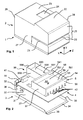
- FIG. 1 shows a perspective view of a franking machine from the top left at the front.
- the top view in the X direction of the YZ plane in the Cartesian coordinate system corresponds to a view of the franking machine from the front.
- the top view against the Y direction on the XZ plane in the Cartesian coordinate system corresponds to a view of the franking machine from above.
- the top view in the Z direction of the XY plane in the Cartesian coordinate system corresponds to a view of the franking machine from the left on its inbox side 27.
- a removable upper housing part 2 is arranged in the Y direction above the lower housing part 1.
- the franking machine has a divided front.
- the front side 25, the incoming mail side 27 and the outgoing side 28 (not visible) of the upper housing part 2 have a slot-shaped opening 21 for a mail item to be franked, which can be fed in the Z direction.
- Below the opening 21 there is a separately removable housing part 29 with a letter running surface.
- the upper side of the housing has a surface 22 which is inclined towards the front side 25 and which is suitable for accommodating a user interface (not shown).
- An opening 24 is arranged on the upper side 23 of the housing, which adjoins the inclined housing surface 22 in the X direction and which is delimited by a rear side 26 of the housing.
- a printing module is moved to a position adjacent to the printing position, from which an ink cartridge can be removed or replaced. Only an authorized person, for example a service technician, may remove additional housing parts. After removing the lower housing part 1 and upper part 2 there remains a chassis arrangement which has a number of chassis parts arranged in the Y direction over a lower housing part 1.
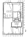
- FIG. 2 shows a perspective view of a chassis arrangement in an exploded view, which mechanically protects components 142 connected to one another on a printed circuit board 4 in the inner security area, which belong to the control unit of the franking machine and for which heat dissipation is made possible by forced convection of an air flow to the outside.
- a lower shell 3 formed for protection and support purposes and the printed circuit board 4
- an upper shell 5 is arranged, which is shaped accordingly for protection and support purposes.
- the upper shell 5 can have a group of outer ventilation openings arranged in a row, which are preferably incorporated in a slot shape on the outer edge.
- the lower shell 3 consists of a shielding and supporting plate 31 which is parallel to the lower housing part 1 and a rear shielding and supporting plate part 36 which is angled parallel to the rear of the housing 26 and which has at least one opening 39 for discharging a heated air flow to the outside.
- At least one component 41 is arranged in the Y direction above the printed circuit board 4 and is accessible through an opening 32 in the angled rear shielding and support plate part 36.
- the aforementioned component 41 which is accessible from the outside, is, for example, a plug / socket for a mains plug cable.
- At least one group 42 of (only partially visible) components is arranged in the Y direction above the printed circuit board 4 and can be covered in a tamper-proof manner by the upper shell 5 which can be placed thereon.
- the shielding and support plate 31 is parallel to the XZ plane and has for this purpose on its side edges angled to the inbox side 27 and to the outbox side 28 and thereby parallel to the XY plane side edge surfaces 37 and 38.
- the rear shielding and support plate part 36 is parallel to the YZ plane and has angled side edge surfaces 33 and 34 on the side edges to the incoming mail page 27 and to the outgoing page 28 and thereby running parallel to the XY plane (not visible).
- the lower shell 3 has a front sheet metal part 35 which is angled parallel to the shielding and support plate 31 and to the front of the housing 25 and in this case runs up to the functional edge parallel to the YZ plane and has an apron 34 which runs parallel to the xz plane.
- the transition to the aforementioned apron 34 of the lower shell 3 is the one functional edge of the lower shell 3, which in the assembled state is spaced apart from the other functional edge 54 of the upper shell 5.
- the lower shell 3 serves, on the one hand, to transmit power to the lower safety housing part 1 and, on the other hand, to dissipate power loss and to comply with the EMC standard.
- the upper chassis shell 5 is delimited on the front side in the Y direction by the functional edge 54 and parallel to the front side or by a functional edge 541 parallel to the rear side in the Y direction.
- the functional edge 54 of the upper chassis shell 5 is reversed U-shaped, that is to say,-shaped, and has an inner side wall 53 arranged near the front side and an outer front side wall 55.
- the functional edge 54 of the upper chassis shell 5 is the further ⁇ -shaped functional edge 541 with an inner side wall 531 and an outer rear side wall 551 spaced in the X direction.
- a side wall 57 or 58 delimits the chassis upper shell 5 on the post-stream input or post-stream output side.
- a plate 56 lying parallel to the shielding and support plate 31 divides the inner cavity into a lower cavity and an upper cavity 60.
- the lower cavity (not visible) is intended to accommodate accounting and control electronics for printing and belongs to the internal security area.
- the upper cavity 60 is provided for receiving a pressure mechanism.
- An opening 561 is arranged in the plate 56 for the passage of cables.
- a box 59 can be arranged on the chassis upper shell 5, which extends, for example, in the X direction to the box rear wall 596 and is delimited in the Z direction, ie downstream, by a box side wall 598 or in the opposite direction, ie upstream, by a box side wall 599 becomes. If the box 59 has a box bottom 590, as shown, then at least one opening 591 for electrical cables is provided in the latter.
- the box 59 has, for example, a greater length in the X direction up to the box rear wall 596 than in the Z direction.
- the box side wall 599 is arranged in the middle of the length in the Z direction on the outer side wall 551, all walls preferably having the same height in the Y direction.
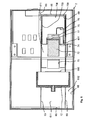
- FIG. 3 shows a perspective view of assembled chassis parts 3, 4, 5 and 6.
- the printed circuit board 4 equipped with components from groups 42 and 45 rests on the front of the apron 34 of the lower shell 3.
- the chassis upper shell 5 is supported with its side walls on the printed circuit board 4.
- Each of the side walls 57 and 58 are equipped with fastening means 571 and 572 or - not visible - fastening means 581 and 582 in order to fasten the upper chassis shell 5 to the lower chassis shell 3 on the post-flow output side.
- a support frame 6 is arranged above their functional edges 54, 541 as a further chassis part for supporting the printing mechanism.
- the support frame 6 is delimited by side walls 67 and 68, respectively, on the incoming and outgoing flow side.
- the support frame 6 has a length in the Z direction from one side wall 67 to the other 68, which is divided in the middle by a partition wall 63 into two rectangular boxes, that is to say a box located on the mail flow entry side with a first base area and one on the post flow exit page located box with a second footprint, the box located on the incoming mail side has a smaller footprint than the box located on the outgoing mail side.
- the box located on the mail flow input side is delimited by a rear side wall 62 located in the X direction, the partition wall 63, a front side wall 64 and the side wall 67 and has a base plate 61 with the first base area.
- the dividing wall 63 merges in the X direction into a side wall of the box located on the post-flow exit side, the side wall being aligned with the side wall 599 of the box arranged below it.
- the box arranged above also has a front side wall 65 and rear side wall 66 located in the X direction. All of the aforementioned walls 62, 63, 64, 65, 66, 67 and 68 are shown cut open in height in order to make parts of the printing mechanism visible.
- a mail item (not shown) is transported in the transport direction Z by a driven transport drum (shown in FIGS. 4, 5 and 6) which is arranged opposite at least one spring-loaded counter-pressure roller 11 (shown in FIGS. 3 and 6).
- a printing module 7 has a protective cap 73 and carries at least one replaceable ink cartridge 72 which can be fastened on a printing carriage 74.
- the protective cap 73 has two side walls 733, 739 and a rear side wall 736 and a ceiling plate 731. The latter has a sealing and guide strip 732.
- a filled envelope is moved by means of a transport drum protruding through an opening 692 in a base plate 611 of the support frame 6 during the printing in the transport direction Z at a predetermined speed.
- the box located on the post stream exit side has a further partition 69 extending in the X direction parallel to the partition 63 to limit the base plate 611 in the Z direction.
- Both partition walls 63, 69 have openings 631, 691 for the transport drum which are spaced apart in the Z direction and close to the printing position.
- a further base plate 612 can be arranged on the same level as the base plate 61 between the partition 69 and the side wall 68 on the side of the mail flow, through which a postal item to be franked, the slot-shaped opening 21 of the upper housing part, not shown - shown in FIG. 1 - is shown 2 inserted, ie fed in the Z direction, is limited in its thickness from the letter running surface 290 in the Y direction.
- the side wall 57 and the side wall 58 are equipped with bolts 571 and 581 (not visible) as fastening means.
- the bolt is rotatably mounted in a bearing opening 371 or 381 (not visible) of the side edge surfaces 37 or 38 (not visible), about which the upper chassis shell 5 can be rotated when the other fastening means 572 and 582 (not visible) are released.
- Common fasteners are breakaway screws or lead screws.
- the security area protected in this way can still have a high security area internally. Encapsulation of the high-security area by means of another housing offers additional mechanical protection.
- a security module was developed for such a high-security area, which is equipped with an accounting unit, with a cryptographic unit for securing the postage fee data to be printed and with its own security housing.
- the chassis lower shell 3 has ventilation openings 39 in the rear shielding and support plate part 36 and, if necessary, ventilation openings not shown in the printed circuit board 4 near the component 41.
- FIG. 4 Using a top view of a franking machine shown in FIG. 4, which is cut in an XZ plane, becomes the location of the print module clarified in print position.
- the latter is in the middle box of the support frame over the area between the two aforementioned Functional edges 54, 541 of the upper chassis shell.
- the back of the case 26 is designed in a suitable manner, one through which is to be removed Dissipate the power loss of the heated air flow and with suitable connector sockets to insert pluggable power cord and record telephone and interface cables, etc.
- At the The rear of the housing 26 of the upper housing part 2 is a corresponding one Component 41 arranged on the printed circuit board 4, the lower chassis shell 3 and the chassis upper shell 5 a security area limit the circuit board 4.
- The is parallel to the rear of the housing 26 Rear wall 66 of the box 63, 65, 66, 69 of the support frame, which for receiving the printing module and the transport drum 12 is predetermined.
- the latter is arranged near the front 25 and shown cut through its axis of rotation.
- the treads on the The outer diameters of the protrusions are partly in boxes 62, 63, 64 and 67 with the bottom surface 61 or in the box with the side walls 68, 69 and with the floor surface 612, which is near the inbox side 27 or inbox page 28 are arranged.
- the axis of rotation of the Transport drum 12 is parallel to the X axis.
- the transport drum 12 On the back 26 facing side, the transport drum 12 has an opening in which the cartridge 72 is shown partially retracted.
- Bottom plate 611 In the Bottom plate 611 is an opening 692 in the region of the transport drum 12 provided, through which a force from the transport drum 12 is exerted on the mail piece to the mail piece in the Z direction transport.
- An opening intended for franking is due the cartridge position is not visible, but can be so close to the opening 692 lie that both openings adjoin each other.
- Box 63, 65, 66, 69 of the support frame, which for receiving the printing module is provided, has a cable entry opening 601 in the base plate 611, which is in the X direction from that intended for franking printing Opening is removed. This opening 601 lies within the the protective cap 73 covered area.
- the protective cap 73 is on a printing carriage 74 attached, which has an interface 77 for at least carries a replaceable ink cartridge 72.
- the protective cap 73 has two side walls 733, 739 and a rear side wall 736 and one (in 4) ceiling plate 731.
- a flexible ribbon cable 76 connects the control located in the security area to the printhead control electronics 75 on the printing carriage 74. If now the Printing carriage 74 is moved up to a stop plate 78 and thus reached the printing position, then the stretch for the flexible Ribbon cable 76 from the cable entry opening 601 to the connection stretched on printhead drive electronics 75.
- FIG. 5 Using a top view of a franking machine shown in FIG. 5, which is cut in an XZ plane, becomes the location of the print module clarified in the cartridge change position.
- the latter is in the middle box 63, 65, 66 and 69 of the support frame over the area between the aforementioned functional edge 541 of the upper chassis shell and the box rear wall located towards the rear of the housing 26 66.
- the protective cap 73 with side walls 733, 739 and the rear side wall 736 is with the printing carriage 74 away from the stop plate 78 in the X direction process, the rear wall 736 to reach the Cartridge change position brought close to the back wall 66 of the box becomes.
- the cartridge 72 is now of the Opening 70 in the bottom plate 611 of the middle box of the support frame so far that they are exactly under the opening in the upper part of the housing lies.
- the protective cap 73 is to enclose the protective changing area and not disturbing for a Replacing the cartridge 72 is formed.
- FIG. 6 shows a perspective view from the right of a cut franking machine, with the upper housing part 2 with the slot 21 for feeding mail on the side wall (not visible) of the inbox and with the side wall 28 on the outgoing mail side, with the housing part 29 on the front side 25 of the upper housing part 2, with the partition wall 15 on the lower housing part 1, with the group 51 of openings in the front side wall 55 of the chassis upper shell 5, with the partition wall 63, with the at least one replaceable ink cartridge 72, with the transport drum 12 and the at least one counter-pressure roller 11 in your Arrangement to one another, the latter being arranged in the space 60 of the upper chassis shell 5, which is separated by the base plate 56 from the space 50 for the components arranged on the printed circuit board 4 in the security area.
- the printing module arranged transversely to the transport direction Z has a corresponding printing carriage 74. More detailed explanations can be found in the unpublished German patent application 100 32 855.5, which has the title carries: device for printing on a printing medium.
- the ribbon cable 76 is guided from the printed circuit board 4 through the base plate 611 to the connection to the printer control electronics 75.
- the protective cap 73 prevents access to the data and control lines in the ribbon cable 76 not only during printing, ie when the printing carriage 74 is brought into the printing position for printing with an opening 70 in the base plate 611 with the at least one replaceable ink cartridge 72 or printer control electronics 75.
- the protective cap 73 is fastened to the printing carriage 74 and closes the aforementioned opening 24 in the housing, correspondingly more or less during the movement of the printing carriage towards or away from the printing position.
- the aforementioned opening 24 is not / not completely closed by the protective cap 73, so that there is a risk of an accident that when reaching into the aforementioned opening 24, the printing carriage 74 moves straight by hand becomes.
- a cover 20 is therefore required, for example a flap, which can, however, be opened at any time.
- a microswitch 81 then switches off the transverse movement means (not shown) and prevents transverse movement of the printing carriage 74.
- a sensor 82 can be used which detects the flap position 'open' before the switch-off is initiated.
- FIG. 7 shows a perspective view of a protective cap 73 'according to a second variant.
- the protective cap 73 ' has two side walls 733', 739 'and a ceiling plate 731'.
- the latter has a sealing and Guide bar 732 '.
- Both side walls 733 ', 739' are in the X direction, i.e. to the back 66 of the middle box of the support frame down, reduced in area.
- an opening 730 'for a Replacement of at least one ink cartridge 72 is provided.
- FIGS. 8a and b show further perspective views of a Protective cap 73 "shown according to a third variant.
- the ceiling plate 731 " is reduced in length in the X direction and a sealing and Guide bar is omitted.
- the protective cap 73 " after the third variant also a rear wall 736 "next to two side walls 733 ", 739" and a ceiling plate 731 ". In the latter can also have an opening 730 "for replacement at least one ink cartridge 72 may be provided.
- the back wall However, 736 " is compared to the first variant shown in FIG. 3 halved in an XZ plane.
- the missing second half to to the base plate on the back of the protective cap 73 " is by a Middle plate 737 "of a protective cap lower part supplemented or covered, which with two angled side walls 734 ", 735" in plan view forms an angular lying U-profile.
- the length of the side walls 734 "angled from the center plate 737", 735 is approximately twice as long in the X direction as the length of the Sidewalls 733 ", 739” in the X direction. This allows a shift the lower part of the protective cap relative to the upper part of the protective cap.
- the top surface 738 "of the protective cap lower part has an angled one Stop 7381 ", which is a displacement of the protective cap lower part limited to the top cap relative to each other.
- FIG. 8b is a perspective view of the telescope sliding protective cap 73 "shown in opposite Direction, i.e. to the printing position.
- This third variant with telescopic shift is for mail processing equipment with a shallow depth is particularly suitable.
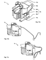
- Fig. 9a is a perspective view from the top right front the printing module shown according to a fourth variant.
- the printing module 7a has a protective cap 73a attached to the printing carriage 74a and two Ink cartridges 72a and 72b carried by the printing carriage 74a become. The latter can be activated from the print position the transverse movement means 17 from the illustrated printing position into one Ink cartridge change position to be moved.
- On the printing carriage 74a is laterally attached to a carriage 79 with a connection 71 for the ribbon cable 76a.
- the carriage 79 is attached to the printing carriage 74a in the Z direction. However, this should not rule out the alternative of a sledge on the opposite side of the print carriage from the Z direction 74 can be attached.
- a guide channel 14 extends laterally of the printing module 7a in the X direction and is used for guidance and protection the ribbon cable 76a from unauthorized access to its electrical Cables.
- the guide channel 14 In the Y direction, i.e. upwards, the guide channel 14 limited by a protective wall 13.
- In the X direction there is an elbow on the end 18 trained.
- the guide channel 14 with the protective wall 13 and the elbow 18 is attached to the support frame 6 (not shown).
- the ribbon cable 76a becomes in the Y direction from the security area to the non-security area guided and runs parallel to the Z direction after folding.
- the ribbon cable 76a lies folded on the angle piece 18 indicates that its flat side is parallel to the YZ plane. After a further folding, the ribbon cable 76a runs in the guide channel 14 parallel to the X direction.
- the ribbon cable 76a contains at the connection 71 electrical lines lined up in a line parallel to the Z direction and is arranged with its flat side parallel to the XZ plane.
- the side view shown in FIG. 9b from the right onto the guide channel of the printing module 7a according to the fourth variant shows an enlarged one Section of the guide channel 14 with the slide 79 and the connection 71 for the ribbon cable 76a.
- the ribbon cable 76a is flexible and bent in a U shape in the XY plane.
- the ribbon cable 76a is at Moving the carriage inside the guide channel 14, wherein the U-shaped arc moves in the X direction or opposite to it becomes.
- a parallel duct wall 15 is spaced from the protective wall 13, where the distance D is greater than the smallest allowable bending radius of the ribbon cable 76a.
- the top view of the printing module shown in FIG. 9c according to FIG fourth variant illustrates how on the one hand the printhead control electronics (not visible) through the protective cap 73a and on the other hand the ribbon cable 76a through the protective wall 13 against an unauthorized person Access is protected from above.
- Ink cartridges are locked by operating levers 10a and 10b are opened and then new ink cartridges 72a, 72b in the print carriage 74a inserted, the ink printheads over the Interfaces 77a and 77b with the printhead drive electronics (not visible) to be contacted. Then the lock restored by levers 10a and 10b.
- the side view of the printing module is from the left of the fourth variant, wherein the printing module 7a is in the printing position located.
- the movement space of the pressure module 7a is in the Z direction bounded by a guide wall 19, which with the protective wall 13 forms the guide channel.
- Print carriage 74a carries printhead drive electronics 75 (drawn in broken lines, as not visible), which via interfaces 71a, 71b with the ink cartridges 72a, 72b is connectable and is covered by the protective cap 73a, wherein whose slide 79 in a guide slot 191 of the guide wall 19th runs and extends in the X direction.
- 10a is a perspective view from behind of the Pressure module shown according to the fourth variant, which is Printing module 7a is in the printing position.
- Figure 10b is a rear perspective view of the Printing module shown according to the fourth variant, the printing module 7a in a position farthest from the printing position for example in the cartridge change position.
- the protective cap 73a made contact with the inner wall of the angle piece 18.
- Both figures illustrate the folds of the parallel to the Z direction guided ribbon cable 76 a, which abuts the elbow 18. For every Folding is required to change the direction of the ribbon cable 76a.
- FIG 11a is a perspective view from the front of the Printing module shown according to a fifth variant, the Connection of the ribbon cable 76b on the back of the printing carriage 74b, i.e. is located on the protective cap 73b and the ribbon cable 76b in a Z-direction parallel line contains lined up electrical lines and with its flat side is arranged parallel to the XZ plane.
- the Ribbon cable 76b is within the range of motion of the printing module 7b, the movement space through the walls 63, 65, 66 and 69 of the box is limited within the support frame (Fig. 4).
- the ribbon cable 76b is protected by a special flexible protective casing 9b against an unauthorized person Access protected.
- the protective casing 9b consists of a flattened Hose piece 94b and goes into the protective cap at one end 73b via that for covering the printhead drive electronics serves.
- the tube piece 94b is for receiving a strip conductor 76b formed and preferably has a non-positive and positive connection with the protective cap 73b, which is designed for strain relief is.
- the protective cap 73b is designed for attachment to the printing module 7b, the fastening means being arranged so that the latter are inaccessible from access through opening 24.
- the protective jacket 9b leads at the other end to a connector 99b which for example, can be attached to the support frame 6 (FIG. 3) via a holder 98b is and which is designed for strain relief.
- the hose piece 94b becomes, for example, a particularly tough one Made of plastic and is flexible.
- the hose piece 94b has an all-round metallic shield, not shown, for Example of a flexible internal copper wire mesh.
- FIG. 11b shows the side view from the left of the printing module of the fifth variant, wherein the printing module 7b is in the printing position located.
- FIG. 11b shows the side view from the left of the printing module the fifth variant, wherein the printing module 7b in Cartridge change position is located.
- FIG. 9a shows the perspective view of the printing module according to the fourth variant, an interconnection with a switch 81 shown, at least temporarily in mechanical contact with a removable cover (not shown).
- a switch 81 or a sensor 82 are via a control circuit 83 with a stepper motor 16 for driving the transverse movement means 17 connected.
- a spindle for example, serves as the transverse movement means 17, which cooperates with the printing carriage, in accordance with the direction of rotation to achieve a transverse movement of the spindle.
- the switch 81 is on the one hand with a supply voltage (not shown) and on the other hand connected to the control circuit 83 and switches the supply voltage to when a cover to replace the opening closes at least one ink cartridge. It is envisaged that the Transverse movement means 17 on a transverse movement of the printing module 7 be prevented after opening a cover (not shown) or the opening (shown in FIG. 1) in the housing 2 has been removed covers.
Abstract
Description
- Figur 1,
- perspektivische Ansicht einer Frankiermaschine,
- Figur 2,
- perspektivische Ansicht einer Chassisanordnung,
- Figur 3,
- perspektivische Ansicht von montierten Chassisteilen,
- Figur 4,
- Draufsicht auf eine Frankiermaschine, die in einer XZ-Ebene geschnitten ist, mit Druckmodul in Druckposition,
- Figur 5,
- Draufsicht auf eine Frankiermaschine, die in einer XZ-Ebene geschnitten ist, mit Druckmodul in Kartuschenwechselposition,
- Figur 6,
- perspektivische Ansicht von vorn oben rechts einer aufgeschnittenen Frankiermaschine,
- Figur 7,
- perspektivische Ansicht einer Schutzkappe nach einer zweiten Variante,
- Figur 8a, b,
- perspektivische Ansichten einer Schutzkappe nach einer dritten Variante.
- Figur 9a,
- perspektivische Ansicht von vorn oben rechts auf das Druckmodul nach einer vierten Variante in Druckposition,
- Figur 9b,
- Seitenansicht von rechts auf den Führungskanal des Druckmoduls nach der vierten Variante,
- Figur 9c,
- Draufsicht auf das Druckmodul nach der vierten Variante,
- Figur 9d,
- Seitenansicht von links auf das Druckmodul nach der vierten Variante in Druckposition,
- Figur 10a,
- perspektivische Ansicht von hinten auf das Druckmodul nach der vierten Variante in Druckposition,
- Figur 10b,
- perspektivische Ansicht von hinten auf das Druckmodul nach der vierten Variante in Kartuschenwechselposition,
- Figur 11a,
- perspektivische Ansicht von vorn auf das Druckmodul nach einer fünften Variante,
- Figur 11b,
- Seitenansicht von links auf das Druckmodul nach der fünften Variante in Druckposition,
- Figur 11c,
- Seitenansicht von links auf das Druckmodul nach der fünften Variante in Kartuschenwechselposition.
Ein abnehmbares Gehäuseoberteil 2 ist in Y-Richtung über dem Gehäuseunterteil 1 angeordnet. Die Frankiermaschine hat eine geteilte Frontseite. Die Frontseite 25, die Posteingangsseite 27 und die Postausgangsseite 28 (nicht sichtbar) des Gehäuseoberteils 2 weisen eine schlitzförmige Öffnung 21 für ein zu frankierendes Postgut auf, welches in Z-Richtung zuführbar ist. Unterhalb der Öffnung 21 liegt ein separat abnehmbares Gehäuseteil 29 mit einer Brieflauffläche. Die Gehäuseoberseite weist eine zur Frontseite 25 hin geneigte Fläche 22 auf, welche geeignet ist, ein - nicht gezeigtes - Userinterface aufzunehmen. Auf der Gehäuseoberseite 23, welche sich in X-Richtung an die geneigte Gehäuseoberfläche 22 anschließt und welche von einer Gehäuserückseite 26 begrenzt wird, ist eine Öffnung 24 angeordnet. Für den Benutzer ist eine - in der Fig. 1 nicht gezeigte - Klappe als Abdeckung vorgesehen, welche die vorgenannte Öffnung 24 abdeckt und jederzeit geöffnet oder abgenommen werden kann. Nach Eingabe eines unautorisierten Signals wird ein Druckmodul in eine zur Druckposition benachbarte Position, aus der eine Tintenkartusche entfernt oder ausgetauscht werden kann. Nur eine dazu authorisierte Person, beispielsweise ein Servicetechniker, darf weitere Gehäuseteile abnehmen. Nach dem Abnehmen des Gehäuseunterteils 1 und -oberteils 2 verbleibt eine Chassisanordnung, welche eine Anzahl von in Y-Richtung über einem Gehäuseunterteil 1 angeordneten Chassisteilen aufweist.
Zusätzlich kann ein Kasten 59 an der Chassisoberschale 5 angeordnet sein, der sich beispielsweise in X-Richtung bis zur Kastenrückwand 596 erstreckt und in Z-Richtung, d.h. poststromabwärts, durch eine Kastenseitenwand 598 bzw. entgegengesetzt dazu, d.h. poststromaufwärts, durch eine Kastenseitenwand 599 begrenzt wird. Wenn der Kasten 59, wie gezeigt ist, einen Kastenboden 590 aufweist, dann ist im letzteren mindestens eine Öffnung 591 für elektrische Kabel vorgesehen. Der Kasten 59 weist beispielsweise in X-Richtung bis zur Kastenrückwand 596 eine größere Länge auf als in Z-Richtung. Die Kastenseitenwand 599 ist in der Mitte der Länge in Z-Richtung an der außen liegenden Seitenwand 551 angeordnet, wobei alle Wände vorzugsweise eine gleiche Höhe in Y-Richtung aufweisen.
Ein Druckmodul 7 hat eine Schutzkappe 73 und trägt mindestens eine auswechselbare Tintenkartusche 72, die auf einem Druckwagen 74 befestigbar ist. Die Schutzkappe 73 hat zwei Seitenwände 733, 739 und eine Rückseitenwand 736 sowie eine Deckenplatte 731. Letztere weist eine Abdicht- und Führungsleiste 732 auf.
Ein gefülltes Briefkuvert wird mittels einer durch eine Öffnung 692 in einer Bodenplatte 611 des Stützrahmens 6 ragenden Tansporttrommel während des Druckens in Transportrichtung Z mit einer vorbestimmten Geschwindigkeit bewegt. Der an der Poststromausgangsseite gelegene Kasten weist parallel zur Trennwand 63 eine weitere sich in X-Richtung erstreckende Trennwand 69 zum Begrenzen der Bodenplatte 611 in Z-Richtung auf. Beide Trennwände 63, 69 weisen in der Nähe des Druckposition gegenüberliegenden in Z-Richtung beabstandete Öffnungen 631, 691 für für die Transporttrommel auf. Zwischen der Trennwand 69 und der poststromausgangsseitigen Seitenwand 68 kann auf der gleichen Ebene wie die Bodenplatte 61 eine weitere Bodenplatte 612 angeordnet sein, durch welche ein zu frankierendes Postgut, das in nicht gezeigter Weise - in der Fig. 1 gezeigte - schlitzförmige Öffnung 21 des Gehäuseoberteils 2 gesteckt, d.h. in Z-Richtung zugeführt wird, in seiner Dicke ab der Brieflauffläche 290 in Y-Richtung begrenzt wird.
Die Seitenwand 57 bzw. die - nicht dargestellte - Seitenwand 58 sind mit Bolzen 571 bzw. 581 (nicht sichtbar) als Befestigungsmittel ausgestattet. Der Bolzen ist in einer Lageröffnung 371 bzw 381 (nicht sichtbar) der Seitenrandflächen 37 bzw. 38 (nicht sichtbar) drehbar gelagert, um welche die Chassisoberschale 5 drehbar ist, wenn die übrigen Befestigungsmittel 572 und 582 (nicht sichtbar) gelöst sind. Übliche Befestigungsmittel sind Wegbrechschrauben oder verplombte Schrauben.
Die Chassisunterschale 3 hat Lüftungsöffnungen 39 im rückwärtigen Abschirm- und Stützblechteil 36 und ggf. nicht gezeigte Lüftungsöffnungen in der Leiterplatte 4 nahe dem Bauteil 41.
Das querbeweglich zur Transportrichtung Z angeordnete Druckmodul hat neben der mindestens einen auswechselbaren Tintenkartusche 72, die in der Druckposition zum Teil in die Transporttrommel 73 hineinragt, einen entsprechenden Druckwagen 74. Nähere Ausführungen dazu sind der nicht vorveröffentlichten deutschen Patentanmeldung 100 32 855.5 entnehmbar, welche den Titel trägt: Vorrichtung zum Bedrucken eines Druckträgers.
Von der Leiterplatte 4 durch die Bodenplatte 611 hindurch wird das Bandkabel 76 bis zum Anschluß an Druckeransteuerungselektronik 75 geführt. Nicht nur während des Druckens, d.h. wenn der Druckwagen 74 zum Drucken mit der mindestens einen auswechselbaren Tintenkartusche 72 in die Druckposition zum Drucken durch eine Öffnung 70 der Bodenplatte 611 gebracht ist, verhindert die Schutzkappe 73 den Zugriff auf die Daten - und Ansteuerleitungen im Bandkabel 76 bzw. Druckeransteuerungselektronik 75. Die Schutzkappe 73 ist am Druckwagen 74 befestigt und verschließt die vorgenannte Öffnung 24 im Gehäuse, entsprechend mehr oder weniger während der Bewegung des Druckwagens in Richtung zur Druckposition hin oder weg. Bei jeder anderen Position, in welche der Druckwagen gebracht werden kann, ist die vorgenannte Öffnung 24 durch die Schutzkappe 73 also nicht/nicht vollständig verschlossen, so dass eine Unfallgefahr besteht, dass bei Greifen in die vorgenannte Öffnung 24 per Hand der Druckwagen 74 gerade verfahren wird. Eine Abdeckung 20 wird deshalb erforderlich, beispielsweise eine Klappe, die aber jederzeit geöffnet werden kann. Ein Mikroschalter 81 schaltet dann die Querbewegungsmittel (nicht gezeigt) ab und verhindert eine Querbewegung des Druckwagens 74. Alternativ kann ein Sensor 82 eingesetzt werden, der die Klappenposition 'offen' ermittelt, bevor die Abschaltung veranlaßt wird.
Es ist eine Vielzahl einer alternativen Chassisanordnung im Rahmen der Ansprüche denkbar, die unterschiedlich ausgeführt sind. So können offensichtlich weitere andere Ausführungen der Erfindung entwickelt bzw. eingesetzt werden, die vom gleichen Grundgedanken der Erfindung ausgehend, die von den anliegenden Ansprüchen umfaßt werden.
Claims (16)
- Anordnung zum Schutz eines Druckmoduls in einem Postverarbeitungsgerät mit einem Stützrahmen (6) für die Druckmechanik im Nichtsicherheitsbereich und mit einem Querbewegungsmittel (17) zur Querbewegung eines Druckmoduls (7), wobei das Druckmodul (7) im Stützrahmen (6) querbeweglich zur Poststücktransportrichtung (Z) angeordnet und mechanisch vor einem unberechtigten Zugriff geschützt ist, gekennzeichnet dadurch, dass eine Schutzkappe (73, 73', 73", 73a, 73b) am Druckwagen (74, 74a, 74b) befestigt ist und zum Umschließen eines zu schützenden Bereiches des lageveränderlichen Druckmoduls (7, 7a, 7b) ausgebildet ist, dessen Bewegungsraum durch die Wände (63, 65, 66 und 69) eines Kastens innerhalb des Stützrahmens (6) begrenzt wird, dass Mittel (81, 82, 83) vorgesehen sind, welche die Querbewegungsmittel (17) an einer Querbewegung des Druckmoduls (7, 7a, 7b) hindern, nachdem eine Abdeckung (20) geöffnet oder entfernt worden ist, welche eine Öffnung (24) im Sicherheitsgehäuseoberteil (2) abdeckt, wobei die Öffnung (24) zum Auswechseln mindestens einer Tintenkartusche (72, 72a, 72b) vorgesehen ist.
- Anordnung, nach Anspruch 1,gekennzeichnet dadurch, dass in der Schutzkappe (73), die zum Umschließen eines zu schützenden Bereiches des lageveränderlichen Druckmoduls ausgebildet ist, eine Öffnung (730) für ein Auswechseln mindestens einer Tintenkartusche (72) vorgesehen ist
- Anordnung, nach Anspruch 1,gekennzeichnet dadurch, dass daß die Abdeckung (20) als Betätigungmittel ausgebildet und als Handschutz vorgesehen ist, der jederzeit geöffnet werden kann.
- Anordnung, nach einem der Ansprüche 1 und 3, gekennzeichnet dadurch, dass im Gehäuseoberteil (2) ein Schalter (81) angeordnet ist, der mit der Abdeckung (20) betätigbar ist und bei geöffneter Abdeckung (20) die Querbewegungsmittel abschaltet.
- Anordnung, nach einem der Ansprüche 1 und 3, gekennzeichnet dadurch, dass im Gehäuseoberteil (2) ein Sensor (82) angeordnet ist, der mit der Abdeckung (20) auslösbar ist, um bei geöffneter Abdeckung (20) die Querbewegungsmittel abzuschalten.
- Anordnung, nach Anspruch 1,gekennzeichnet dadurch, dass mindestens zwei voneinander beabstandete Chassisschalen (3, 5) eine Leiterplatte (4) mit dem Sicherheitsbereich umgeben, auf welchen sich ein Stützrahmen für die Druckmechanik im Nichtsicherheitsbereich abstützt, wodurch der Nichtsicherheitsbereich mit dem Druckmodul (7) und die Öffnung (24) im Sicherheitsgehäuseoberteil (2) vom Sicherheitsbereich beabstandet sind.
- Anordnung, nach einem der Ansprüche 1 und 3 bis 5, gekennzeichnet dadurch, dass die Abdeckung (20) eine Klappe ist.
- Anordnung, nach Anspruch 1,gekennzeichnet dadurch, dass die Schutzkappe (73') mindestens zwei Seitenwände (733', 739') und eine Deckenplatte (731') aufweist.
- Anordnung, nach Anspruch 1,gekennzeichnet dadurch, dass die Schutzkappe (73") mindestens zwei Seitenwände (733", 739") und eine Deckenplatte (731") sowie eine Rückseitenwand (736") aufweist.
- Anordnung, nach Anspruch 8, gekennzeichnet dadurch, dass die Deckenplatte (731) der Schutzkappe (73) eine Abdicht- und Führungsleiste 732 aufweist.
- Anordnung, nach Anspruch 9, gekennzeichnet dadurch, dass die Schutzkappe (73") ein Schutzkappenoberteil mit zwei Seitenwänden (733", 739"), einer Deckenplatte (731") sowie einer halben Rückseitenwand (736") und ein Schutzkappenunterteil mit zwei abgewinkelten Seitenwänden (734", 735") von einer Mittelplatte (737") aufweist, wobei letztere die fehlende Hälfte Rückseitenwand (736") ersetzt und wobei von der Mittelplatte (737") eine Deckfläche (738") abgewinkelt ist, so dass die Seitenkanten der Deckfläche (738") parallel zu den Seitenkanten der Seitenwände (734", 735") liegen, dass die Deckfläche (738") des Schutzkappenunterteils am von der Mittelplatte (737") entfernten Ende einen abgewinkelten Anschlag (7381") aufweist, welcher eine Verschiebung des Schutzkappenunterteils zum Schutzkappenoberteil relativ zueinander begrenzt.
- Anordnung, nach Anspruch 1,gekennzeichnet dadurch, dass die Schutzkappe (73, 73b) eine Druckkopfansteuerungselektronik (75) und ein Bandkabel (76, 76b) abdeckt, wobei das Bandkabel (76, 76b) innerhalb des Bewegungsraumes des Druckmoduls (7, 7b) geführt wird.
- Anordnung, nach Anspruch 12, gekennzeichnet dadurch, dass das Bandkabel (76b) durch eine spezielle flexible Schutzummantelung (9b) gegen einen unberechtigten Zugriff geschützt ist.
- Anordnung, nach Anspruch 1,gekennzeichnet dadurch, dass die Schutzkappe (73a) eine Druckkopfansteuerungselektronik (75) und ein Bandkabel (76a) abdeckt, wobei das Bandkabel (76a) außerhalb des Bewegungsraumes des Druckmoduls (7a) in einem Führungskanal (14) geführt wird, der in X-Richtung endseitig ein Winkelstück (18) aufweist.
- Anordnung, nach Anspruch 14, gekennzeichnet dadurch, dass das Bandkabel (76a) an dem Winkelstück (18) anliegt und mindestens eine Faltung aufweist und dass der Führungskanal (14) aus einer Führungswand (19), einer Schutzwand (13) und einer dazu parallelen Kanalwand (15) gebildet ist, wobei der Bewegungsraum des Druckmoduls (7a) in Z-Richtung durch die Führungswand (19) begrenzt ist sowie dass dier Schutzwand (13) und Kanalwand (15) voneinander so beabstandet sind, dass der Abstand (D) größer als der kleinste zulässige Biegeradius des Bandkabels (76a) ist.
- Anordnung, nach Anspruch 15, gekennzeichnet dadurch, dass ein Schlitten (79) am Druckwagen (74a) seitlich befestigt ist und in einem Führungsschlitz (191) der Führungswand (19) verläuft, wobei sich der Führungsschlitz (191) in X-Richtung erstreckt sowie dass der Schlitten (79) mit einem Anschluß (71) für das Bandkabel (76a) ausgestattet ist.
Applications Claiming Priority (2)
| Application Number | Priority Date | Filing Date | Title |
|---|---|---|---|
| DE10164527 | 2001-12-15 | ||
| DE10164527A DE10164527A1 (de) | 2001-12-15 | 2001-12-15 | Anordnung zum Schutz eines Druckmoduls in einem Postverarbeitungsgerät |
Publications (2)
| Publication Number | Publication Date |
|---|---|
| EP1320076A1 true EP1320076A1 (de) | 2003-06-18 |
| EP1320076B1 EP1320076B1 (de) | 2005-05-11 |
Family
ID=7711180
Family Applications (1)
| Application Number | Title | Priority Date | Filing Date |
|---|---|---|---|
| EP02026747A Expired - Lifetime EP1320076B1 (de) | 2001-12-15 | 2002-12-02 | Anordnung zum Schutz eines Druckmoduls in einem Postverarbeitungsgerät |
Country Status (4)
| Country | Link |
|---|---|
| US (1) | US6789892B2 (de) |
| EP (1) | EP1320076B1 (de) |
| AT (1) | ATE295584T1 (de) |
| DE (2) | DE10164527A1 (de) |
Families Citing this family (14)
| Publication number | Priority date | Publication date | Assignee | Title |
|---|---|---|---|---|
| JP4241013B2 (ja) * | 2002-11-26 | 2009-03-18 | 富士ゼロックス株式会社 | 画像形成装置並びにこれに用いられるフレーム構造及びその製造方法 |
| JP2005007830A (ja) * | 2003-06-20 | 2005-01-13 | Brother Ind Ltd | 筐体の通風構造及び筐体の通風構造を備えた印字装置 |
| KR100612019B1 (ko) * | 2004-10-28 | 2006-08-11 | 삼성전자주식회사 | 감열방식 화상형성장치 |
| KR100612020B1 (ko) * | 2004-10-28 | 2006-08-11 | 삼성전자주식회사 | 감열방식 화상형성장치 |
| US7455383B2 (en) * | 2005-12-05 | 2008-11-25 | Silverbrook Research Pty Ltd | Printhead maintenance station having maintenance belt with belt-cleaning station |
| US7452052B2 (en) * | 2005-12-05 | 2008-11-18 | Silverbrook Research Pty Ltd | Printhead maintenance assembly having maintenance belt |
| US7448724B2 (en) * | 2005-12-05 | 2008-11-11 | Silverbrook Research Pty Ltd | Method of maintaining a printhead using a maintenance belt |
| US7445311B2 (en) * | 2005-12-05 | 2008-11-04 | Silverbrook Research Pty Ltd | Printhead maintenance station having maintenance belt |
| US8164911B2 (en) | 2006-08-18 | 2012-04-24 | Delphi Technologies, Inc. | Lightweight electronic device for automotive applications and method |
| DE102008009947A1 (de) * | 2008-02-20 | 2009-08-27 | Knorr-Bremse Systeme für Nutzfahrzeuge GmbH | Vorrichtung zur Aufnahme eines elektrischen/elektronischen Bauteils und entsprechendes Montageverfahren sowie Abdeckung für eine solche Vorrichtung |
| DE202012005904U1 (de) * | 2012-06-15 | 2012-07-16 | Francotyp-Postalia Gmbh | Frankiermaschine |
| TWI498228B (zh) * | 2012-07-09 | 2015-09-01 | Kinpo Elect Inc | 墨水匣限位裝置及應用此墨水匣限位裝置的多功能事務機 |
| US10071548B2 (en) | 2014-08-13 | 2018-09-11 | Durst Phototechnik Ag | Printing module having a printing head that can be exchanged on the front side |
| JP7109944B2 (ja) * | 2018-03-13 | 2022-08-01 | キヤノン株式会社 | 記録装置 |
Citations (3)
| Publication number | Priority date | Publication date | Assignee | Title |
|---|---|---|---|---|
| EP0881086A2 (de) * | 1997-05-28 | 1998-12-02 | Neopost Limited | Sicheres Drückgerät mit einem abnehmbaren Druckkopf |
| EP1095780A1 (de) * | 1999-10-29 | 2001-05-02 | Neopost Limited | Digitaler Druckkopf |
| US6238038B1 (en) * | 1997-12-30 | 2001-05-29 | Neopost Industrie | Secure digital postage print module |
Family Cites Families (6)
| Publication number | Priority date | Publication date | Assignee | Title |
|---|---|---|---|---|
| GB2169875B (en) | 1985-01-19 | 1988-09-14 | Francotyp Postalia Gmbh | Improvements in ribbon cassettes |
| GB9709051D0 (en) | 1997-05-02 | 1997-06-25 | Neopost Ltd | Postage meter with removable print head |
| GB9709049D0 (en) | 1997-05-02 | 1997-06-25 | Neopost Ltd | Postage meter with removable print head |
| DE19748954A1 (de) | 1997-10-29 | 1999-05-06 | Francotyp Postalia Gmbh | Verfahren für eine digital druckende Frankiermaschine zur Erzeugung und Überprüfung eines Sicherheitsabdruckes |
| US6024429A (en) | 1997-10-30 | 2000-02-15 | Pitney Bowes Inc. | Mailing machine including ink jet printing having ink availability checking |
| DE10021250A1 (de) * | 2000-04-22 | 2001-10-25 | Francotyp Postalia Gmbh | Anordnung zur Poststückdetektierung |
-
2001
- 2001-12-15 DE DE10164527A patent/DE10164527A1/de not_active Withdrawn
-
2002
- 2002-12-02 EP EP02026747A patent/EP1320076B1/de not_active Expired - Lifetime
- 2002-12-02 AT AT02026747T patent/ATE295584T1/de active
- 2002-12-02 DE DE50203065T patent/DE50203065D1/de not_active Expired - Lifetime
- 2002-12-16 US US10/320,952 patent/US6789892B2/en not_active Expired - Fee Related
Patent Citations (3)
| Publication number | Priority date | Publication date | Assignee | Title |
|---|---|---|---|---|
| EP0881086A2 (de) * | 1997-05-28 | 1998-12-02 | Neopost Limited | Sicheres Drückgerät mit einem abnehmbaren Druckkopf |
| US6238038B1 (en) * | 1997-12-30 | 2001-05-29 | Neopost Industrie | Secure digital postage print module |
| EP1095780A1 (de) * | 1999-10-29 | 2001-05-02 | Neopost Limited | Digitaler Druckkopf |
Also Published As
| Publication number | Publication date |
|---|---|
| DE10164527A1 (de) | 2003-07-10 |
| US6789892B2 (en) | 2004-09-14 |
| DE50203065D1 (de) | 2005-06-16 |
| US20030112315A1 (en) | 2003-06-19 |
| EP1320076B1 (de) | 2005-05-11 |
| ATE295584T1 (de) | 2005-05-15 |
Similar Documents
| Publication | Publication Date | Title |
|---|---|---|
| EP1320076B1 (de) | Anordnung zum Schutz eines Druckmoduls in einem Postverarbeitungsgerät | |
| EP0147730B1 (de) | Belegcodierer | |
| DE3729342A1 (de) | Sicherheitsdrucker fuer ein wertdrucksystem | |
| EP2073173B1 (de) | Vorrichtung zum Wechseln von Tintenkartuschen | |
| DE69829911T2 (de) | Sicheres Drückgerät mit einem abnehmbaren Druckkopf | |
| EP1300807B1 (de) | Verfahren und Anordnung zum Öffnen eines Sicherheitsgehäuses | |
| DE202010015354U1 (de) | Modular aufgebautes Druckergerät mit einer entnehmbaren kastenförmigen Baueinheit | |
| DE60020649T2 (de) | Schlitten mit Shutzabdeckung für die elektrischen Verbindungskontakte und Aufzeichnungsgerät | |
| EP1615174B1 (de) | Frankiermaschine mit einer Kommunikationseinheit | |
| EP2674921B1 (de) | Frankiermaschine und Verfahren zu deren Wartung | |
| DE3211757C2 (de) | Gehäuseabdeckung für wahlweise mit Endlos- und Einzelpapier betriebene Druckeinrichtungen | |
| DE10164526A1 (de) | Sicherheitschassis | |
| DE3407633A1 (de) | Zusatzdruckvorrichtung fuer eine frankiermaschine | |
| EP1643456B1 (de) | Kassettenaufnahmeeinrichtung mit Zustandserkennung für ein druckendes Postverarbeitungsgerät | |
| DE202018102465U1 (de) | Gutverarbeitungsgerät mit einem Tintenstrahldruckkopf | |
| DE10043023A1 (de) | Sicherungsvorrichtung zum Schutz des Aufhebens einer elektrischen Verbindung durch einen Nichtberechtigten | |
| DE3636353C1 (de) | Plombierbares Gehaeuse fuer Taxameter-Drucker und Taxameter-Datenspeichermodule | |
| DE10149210A1 (de) | Verfahren und Anordnung zum Öffnen eines Sicherheitsgehäuses | |
| DE19511511A1 (de) | Gassack in einem Kraftwagen | |
| EP0965904B1 (de) | Koffer mit integrierten Büro-Arbeitsvorrichtungen | |
| EP1575000A1 (de) | Tachograph mit wechselbarem Drucker | |
| EP0961236A2 (de) | Vorrichtung zum Bedrucken von Postgut | |
| DE3517898C2 (de) | Aufzeichnungsgerät | |
| DE10051768A1 (de) | Verfahren und Anordnung zum Bedrucken eines Poststückes | |
| DE2530390A1 (de) | Haltevorrichtung zur vereinfachten plombierbaren befestigung eines taxameters im fahrzeug |
Legal Events
| Date | Code | Title | Description |
|---|---|---|---|
| PUAI | Public reference made under article 153(3) epc to a published international application that has entered the european phase |
Free format text: ORIGINAL CODE: 0009012 |
|
| AK | Designated contracting states |
Designated state(s): AT BE BG CH CY CZ DE DK EE ES FI FR GB GR IE IT LI LU MC NL PT SE SI SK TR |
|
| AX | Request for extension of the european patent |
Extension state: AL LT LV MK RO |
|
| 17P | Request for examination filed |
Effective date: 20030709 |
|
| AKX | Designation fees paid |
Designated state(s): AT BE BG CH CY CZ DE DK EE ES FI FR GB GR IE IT LI LU MC NL PT SE SI SK TR |
|
| GRAP | Despatch of communication of intention to grant a patent |
Free format text: ORIGINAL CODE: EPIDOSNIGR1 |
|
| GRAS | Grant fee paid |
Free format text: ORIGINAL CODE: EPIDOSNIGR3 |
|
| GRAA | (expected) grant |
Free format text: ORIGINAL CODE: 0009210 |
|
| AK | Designated contracting states |
Kind code of ref document: B1 Designated state(s): AT BE BG CH CY CZ DE DK EE ES FI FR GB GR IE IT LI LU MC NL PT SE SI SK TR |
|
| PG25 | Lapsed in a contracting state [announced via postgrant information from national office to epo] |
Ref country code: TR Free format text: LAPSE BECAUSE OF FAILURE TO SUBMIT A TRANSLATION OF THE DESCRIPTION OR TO PAY THE FEE WITHIN THE PRESCRIBED TIME-LIMIT Effective date: 20050511 Ref country code: SK Free format text: LAPSE BECAUSE OF FAILURE TO SUBMIT A TRANSLATION OF THE DESCRIPTION OR TO PAY THE FEE WITHIN THE PRESCRIBED TIME-LIMIT Effective date: 20050511 Ref country code: IE Free format text: LAPSE BECAUSE OF FAILURE TO SUBMIT A TRANSLATION OF THE DESCRIPTION OR TO PAY THE FEE WITHIN THE PRESCRIBED TIME-LIMIT Effective date: 20050511 Ref country code: FI Free format text: LAPSE BECAUSE OF FAILURE TO SUBMIT A TRANSLATION OF THE DESCRIPTION OR TO PAY THE FEE WITHIN THE PRESCRIBED TIME-LIMIT Effective date: 20050511 Ref country code: SI Free format text: LAPSE BECAUSE OF FAILURE TO SUBMIT A TRANSLATION OF THE DESCRIPTION OR TO PAY THE FEE WITHIN THE PRESCRIBED TIME-LIMIT Effective date: 20050511 Ref country code: CZ Free format text: LAPSE BECAUSE OF FAILURE TO SUBMIT A TRANSLATION OF THE DESCRIPTION OR TO PAY THE FEE WITHIN THE PRESCRIBED TIME-LIMIT Effective date: 20050511 Ref country code: EE Free format text: LAPSE BECAUSE OF FAILURE TO SUBMIT A TRANSLATION OF THE DESCRIPTION OR TO PAY THE FEE WITHIN THE PRESCRIBED TIME-LIMIT Effective date: 20050511 |
|
| REG | Reference to a national code |
Ref country code: GB Ref legal event code: FG4D Free format text: NOT ENGLISH |
|
| REG | Reference to a national code |
Ref country code: CH Ref legal event code: NV Representative=s name: ROTTMANN, ZIMMERMANN + PARTNER AG Ref country code: CH Ref legal event code: EP |
|
| REG | Reference to a national code |
Ref country code: IE Ref legal event code: FG4D Free format text: LANGUAGE OF EP DOCUMENT: GERMAN |
|
| REF | Corresponds to: |
Ref document number: 50203065 Country of ref document: DE Date of ref document: 20050616 Kind code of ref document: P |
|
| PG25 | Lapsed in a contracting state [announced via postgrant information from national office to epo] |
Ref country code: GR Free format text: LAPSE BECAUSE OF FAILURE TO SUBMIT A TRANSLATION OF THE DESCRIPTION OR TO PAY THE FEE WITHIN THE PRESCRIBED TIME-LIMIT Effective date: 20050811 Ref country code: BG Free format text: LAPSE BECAUSE OF FAILURE TO SUBMIT A TRANSLATION OF THE DESCRIPTION OR TO PAY THE FEE WITHIN THE PRESCRIBED TIME-LIMIT Effective date: 20050811 Ref country code: SE Free format text: LAPSE BECAUSE OF FAILURE TO SUBMIT A TRANSLATION OF THE DESCRIPTION OR TO PAY THE FEE WITHIN THE PRESCRIBED TIME-LIMIT Effective date: 20050811 Ref country code: DK Free format text: LAPSE BECAUSE OF FAILURE TO SUBMIT A TRANSLATION OF THE DESCRIPTION OR TO PAY THE FEE WITHIN THE PRESCRIBED TIME-LIMIT Effective date: 20050811 |
|
| PG25 | Lapsed in a contracting state [announced via postgrant information from national office to epo] |
Ref country code: ES Free format text: LAPSE BECAUSE OF FAILURE TO SUBMIT A TRANSLATION OF THE DESCRIPTION OR TO PAY THE FEE WITHIN THE PRESCRIBED TIME-LIMIT Effective date: 20050822 |
|
| GBT | Gb: translation of ep patent filed (gb section 77(6)(a)/1977) |
Effective date: 20050902 |
|
| PG25 | Lapsed in a contracting state [announced via postgrant information from national office to epo] |
Ref country code: PT Free format text: LAPSE BECAUSE OF FAILURE TO SUBMIT A TRANSLATION OF THE DESCRIPTION OR TO PAY THE FEE WITHIN THE PRESCRIBED TIME-LIMIT Effective date: 20051019 |
|
| PG25 | Lapsed in a contracting state [announced via postgrant information from national office to epo] |
Ref country code: CY Free format text: LAPSE BECAUSE OF FAILURE TO SUBMIT A TRANSLATION OF THE DESCRIPTION OR TO PAY THE FEE WITHIN THE PRESCRIBED TIME-LIMIT Effective date: 20051202 |
|
| REG | Reference to a national code |
Ref country code: IE Ref legal event code: FD4D |
|
| PG25 | Lapsed in a contracting state [announced via postgrant information from national office to epo] |
Ref country code: LU Free format text: LAPSE BECAUSE OF NON-PAYMENT OF DUE FEES Effective date: 20051231 Ref country code: MC Free format text: LAPSE BECAUSE OF NON-PAYMENT OF DUE FEES Effective date: 20051231 Ref country code: BE Free format text: LAPSE BECAUSE OF NON-PAYMENT OF DUE FEES Effective date: 20051231 |
|
| RAP2 | Party data changed (patent owner data changed or rights of a patent transferred) |
Owner name: FRANCOTYP-POSTALIA GMBH |
|
| NLT2 | Nl: modifications (of names), taken from the european patent patent bulletin |
Owner name: FRANCOTYP-POSTALIA GMBH Effective date: 20060104 |
|
| PLBE | No opposition filed within time limit |
Free format text: ORIGINAL CODE: 0009261 |
|
| STAA | Information on the status of an ep patent application or granted ep patent |
Free format text: STATUS: NO OPPOSITION FILED WITHIN TIME LIMIT |
|
| ET | Fr: translation filed | ||
| 26N | No opposition filed |
Effective date: 20060214 |
|
| BERE | Be: lapsed |
Owner name: FRANCOTYP-POSTALIA A.G. & CO. KG Effective date: 20051231 |
|
| REG | Reference to a national code |
Ref country code: CH Ref legal event code: PFA Owner name: FRANCOTYP-POSTALIA AG & CO. KG Free format text: FRANCOTYP-POSTALIA AG & CO. KG#TRIFTWEG 21-26#16547 BIRKENWERDER (DE) -TRANSFER TO- FRANCOTYP-POSTALIA AG & CO. KG#TRIFTWEG 21-26#16547 BIRKENWERDER (DE) |
|
| REG | Reference to a national code |
Ref country code: GB Ref legal event code: 746 Effective date: 20130319 |
|
| REG | Reference to a national code |
Ref country code: DE Ref legal event code: R081 Ref document number: 50203065 Country of ref document: DE Owner name: FRANCOTYP-POSTALIA GMBH, DE Free format text: FORMER OWNER: FRANCOTYP-POSTALIA AG & CO. KG, 16547 BIRKENWERDER, DE Effective date: 20130319 |
|
| REG | Reference to a national code |
Ref country code: GB Ref legal event code: 732E Free format text: REGISTERED BETWEEN 20130516 AND 20130522 |
|
| REG | Reference to a national code |
Ref country code: GB Ref legal event code: 732E Free format text: REGISTERED BETWEEN 20130523 AND 20130529 |
|
| REG | Reference to a national code |
Ref country code: DE Ref legal event code: R084 Ref document number: 50203065 Country of ref document: DE Effective date: 20130314 |
|
| PGFP | Annual fee paid to national office [announced via postgrant information from national office to epo] |
Ref country code: DE Payment date: 20141017 Year of fee payment: 13 |
|
| REG | Reference to a national code |
Ref country code: DE Ref legal event code: R081 Ref document number: 50203065 Country of ref document: DE Owner name: FRANCOTYP-POSTALIA GMBH, DE Free format text: FORMER OWNER: FRANCOTYP-POSTALIA GMBH, 16547 BIRKENWERDER, DE Effective date: 20150330 |
|
| REG | Reference to a national code |
Ref country code: FR Ref legal event code: PLFP Year of fee payment: 14 |
|
| PGFP | Annual fee paid to national office [announced via postgrant information from national office to epo] |
Ref country code: GB Payment date: 20151221 Year of fee payment: 14 Ref country code: CH Payment date: 20151221 Year of fee payment: 14 |
|
| PGFP | Annual fee paid to national office [announced via postgrant information from national office to epo] |
Ref country code: AT Payment date: 20151222 Year of fee payment: 14 Ref country code: NL Payment date: 20151221 Year of fee payment: 14 Ref country code: FR Payment date: 20151221 Year of fee payment: 14 |
|
| PGFP | Annual fee paid to national office [announced via postgrant information from national office to epo] |
Ref country code: IT Payment date: 20151228 Year of fee payment: 14 |
|
| REG | Reference to a national code |
Ref country code: DE Ref legal event code: R119 Ref document number: 50203065 Country of ref document: DE |
|
| PG25 | Lapsed in a contracting state [announced via postgrant information from national office to epo] |
Ref country code: DE Free format text: LAPSE BECAUSE OF NON-PAYMENT OF DUE FEES Effective date: 20160701 |
|
| REG | Reference to a national code |
Ref country code: CH Ref legal event code: PCAR Free format text: NEW ADDRESS: GARTENSTRASSE 28 A, 5400 BADEN (CH) |
|
| PG25 | Lapsed in a contracting state [announced via postgrant information from national office to epo] |
Ref country code: IT Free format text: LAPSE BECAUSE OF NON-PAYMENT OF DUE FEES Effective date: 20161202 |
|
| REG | Reference to a national code |
Ref country code: CH Ref legal event code: PL |
|
| REG | Reference to a national code |
Ref country code: NL Ref legal event code: MM Effective date: 20170101 |
|
| REG | Reference to a national code |
Ref country code: AT Ref legal event code: MM01 Ref document number: 295584 Country of ref document: AT Kind code of ref document: T Effective date: 20161202 |
|
| GBPC | Gb: european patent ceased through non-payment of renewal fee |
Effective date: 20161202 |
|
| PG25 | Lapsed in a contracting state [announced via postgrant information from national office to epo] |
Ref country code: NL Free format text: LAPSE BECAUSE OF NON-PAYMENT OF DUE FEES Effective date: 20170101 |
|
| REG | Reference to a national code |
Ref country code: FR Ref legal event code: ST Effective date: 20170831 |
|
| PG25 | Lapsed in a contracting state [announced via postgrant information from national office to epo] |
Ref country code: CH Free format text: LAPSE BECAUSE OF NON-PAYMENT OF DUE FEES Effective date: 20161231 Ref country code: AT Free format text: LAPSE BECAUSE OF NON-PAYMENT OF DUE FEES Effective date: 20161202 Ref country code: LI Free format text: LAPSE BECAUSE OF NON-PAYMENT OF DUE FEES Effective date: 20161231 Ref country code: FR Free format text: LAPSE BECAUSE OF NON-PAYMENT OF DUE FEES Effective date: 20170102 |
|
| PG25 | Lapsed in a contracting state [announced via postgrant information from national office to epo] |
Ref country code: GB Free format text: LAPSE BECAUSE OF NON-PAYMENT OF DUE FEES Effective date: 20161202 |