EP1320076A1 - Device for protecting a printing module in a mail processing apparatus - Google Patents
Device for protecting a printing module in a mail processing apparatus Download PDFInfo
- Publication number
- EP1320076A1 EP1320076A1 EP20020026747 EP02026747A EP1320076A1 EP 1320076 A1 EP1320076 A1 EP 1320076A1 EP 20020026747 EP20020026747 EP 20020026747 EP 02026747 A EP02026747 A EP 02026747A EP 1320076 A1 EP1320076 A1 EP 1320076A1
- Authority
- EP
- European Patent Office
- Prior art keywords
- protective cap
- arrangement according
- printing
- ribbon cable
- module
- Prior art date
- Legal status (The legal status is an assumption and is not a legal conclusion. Google has not performed a legal analysis and makes no representation as to the accuracy of the status listed.)
- Granted
Links
Images


Classifications
-
- B—PERFORMING OPERATIONS; TRANSPORTING
- B41—PRINTING; LINING MACHINES; TYPEWRITERS; STAMPS
- B41J—TYPEWRITERS; SELECTIVE PRINTING MECHANISMS, i.e. MECHANISMS PRINTING OTHERWISE THAN FROM A FORME; CORRECTION OF TYPOGRAPHICAL ERRORS
- B41J2/00—Typewriters or selective printing mechanisms characterised by the printing or marking process for which they are designed
- B41J2/005—Typewriters or selective printing mechanisms characterised by the printing or marking process for which they are designed characterised by bringing liquid or particles selectively into contact with a printing material
- B41J2/01—Ink jet
- B41J2/17—Ink jet characterised by ink handling
- B41J2/175—Ink supply systems ; Circuit parts therefor
- B41J2/17503—Ink cartridges
- B41J2/1752—Mounting within the printer
-
- B—PERFORMING OPERATIONS; TRANSPORTING
- B41—PRINTING; LINING MACHINES; TYPEWRITERS; STAMPS
- B41J—TYPEWRITERS; SELECTIVE PRINTING MECHANISMS, i.e. MECHANISMS PRINTING OTHERWISE THAN FROM A FORME; CORRECTION OF TYPOGRAPHICAL ERRORS
- B41J29/00—Details of, or accessories for, typewriters or selective printing mechanisms not otherwise provided for
- B41J29/02—Framework
-
- B—PERFORMING OPERATIONS; TRANSPORTING
- B41—PRINTING; LINING MACHINES; TYPEWRITERS; STAMPS
- B41J—TYPEWRITERS; SELECTIVE PRINTING MECHANISMS, i.e. MECHANISMS PRINTING OTHERWISE THAN FROM A FORME; CORRECTION OF TYPOGRAPHICAL ERRORS
- B41J29/00—Details of, or accessories for, typewriters or selective printing mechanisms not otherwise provided for
- B41J29/54—Locking devices applied to printing mechanisms
-
- G—PHYSICS
- G07—CHECKING-DEVICES
- G07B—TICKET-ISSUING APPARATUS; FARE-REGISTERING APPARATUS; FRANKING APPARATUS
- G07B17/00—Franking apparatus
- G07B17/00185—Details internally of apparatus in a franking system, e.g. franking machine at customer or apparatus at post office
- G07B17/00193—Constructional details of apparatus in a franking system
- G07B2017/00233—Housing, e.g. lock or hardened casing
-
- G—PHYSICS
- G07—CHECKING-DEVICES
- G07B—TICKET-ISSUING APPARATUS; FARE-REGISTERING APPARATUS; FRANKING APPARATUS
- G07B17/00—Franking apparatus
- G07B17/00459—Details relating to mailpieces in a franking system
- G07B17/00508—Printing or attaching on mailpieces
- G07B2017/00516—Details of printing apparatus
- G07B2017/00524—Printheads
- G07B2017/00532—Inkjet
Landscapes
- Physics & Mathematics (AREA)
- General Physics & Mathematics (AREA)
- Accessory Devices And Overall Control Thereof (AREA)
- Pile Receivers (AREA)
- Sorting Of Articles (AREA)
- Separation, Sorting, Adjustment, Or Bending Of Sheets To Be Conveyed (AREA)
Abstract
Description
Die Erfindung betrifft eine Anordnung zum Schutz eines Druckmoduls in einem Postverarbeitungsgerät gemäß des Oberbegriffs des Anspruchs 1. Die Erfindung ist für Geräte mit einem Sicherheitsgehäuse geeignet, welche im Inneren einen Sicherheitsbereich und einen Nichtsicherheitsbereich aufweisen, wobei ein Druckmodul im Nichtsicherheitsbereich beweglich angeordnet ist und vor einem unberechtigten Zugriff geschützt werden muß. Sie kommt insbesondere in Frankiermaschinen, Adressiermaschinen und anderen Postverarbeitungsgeräten mit einer Tintenstrahldruckvorrichtung zum Einsatz.The invention relates to an arrangement for protecting a printing module in a mail processing device according to the preamble of claim 1. The invention is suitable for devices with a safety housing, which inside is a security area and a non-security area have a print module in the non-security area is movably arranged and protected against unauthorized access must become. It comes especially in franking machines, Addressing machines and other mail processing devices with one Inkjet printing device for use.
Die Thermotransfer-Frankiermaschine T1000 der Anmelderin hat einen fest im Gehäuse angeordneten Thermotransfer-Druckkopf zum Drucken eines Frankierabdruckes. Der Frankierabdruck beinhaltet eine zuvor eingegebene und gespeicherte postalische Information einschließlich der Postgebührendaten zur Beförderung des Briefes und wird im Sicherheitsbereich im Inneren des Gehäuses erzeugt und gedruckt. Ein am Gehäuse außen aufgesetztes Fach begrenzt einen Nichtsicherheitsbereich und dient zur Aufnahme einer auswechselbaren Farbbandkassette. Während eine zu dem Fach führende Tür jederzeit geöffnet werden kann, wird der Zugang zum Sicherheitsbereich der Druckvorrichtung durch ein Sicherheitsgehäuse verhindert (US 4.767.228).The applicant's thermal transfer franking machine T1000 has one Thermal transfer printhead fixed in the housing for printing of a franking imprint. The franking imprint contains one before entered and stored postal information including the Postage data to transport the letter and is in the security area created and printed inside the case. A on Casing on the outside of the compartment limits a non-security area and is used to hold a replaceable ribbon cassette. While a door leading to the compartment can be opened at any time access to the security area of the printing device is through a safety housing prevents (US 4,767,228).
Wenn eine Frankiermaschine zu Reparaturzwecken geöffnet werden soll, müssen Abreißschrauben des Sicherheitsgehäuses zerstört werden. In Frankiermaschinen und anderen Postverarbeitungsgeräten mit einem Sicherheitsgehäuse können außerdem Plomben oder Kunststoffteile als weiterer Zugangsschutz zur Mikroprozessorsteuerung und zu den Ansteuerleitungen des feststehenden Druckkopfes eingesetzt werden. Nach einer Reparatur, die ein Öffnen des Sicherheitsgehäuses erfordert, müssen Abreißschrauben des Sicherheitsgehäuses, Plomben oder die dem Zugangsschutz dienende Kunststoffteile ersetzt werden.If a franking machine is to be opened for repair purposes, tear-off screws of the safety housing must be destroyed. In Franking machines and other mail processing devices with one Security enclosures can also be used as seals or plastic parts further access protection to the microprocessor control and to the control lines of the fixed print head. To a repair that requires the safety housing to be opened, must tear off the security housing, seals or the plastic parts serving to protect access are replaced.
Die Frankiermaschine JetMail® der Anmelderin ist mit einer Base und mit einem abnehmbaren Meter ausgestattet. Nur letzteres wird durch ein entsprechend ausgebildetes Gehäuse vor einem Missbrauch geschützt. Im Unterschied dazu muss das Gehäuse der Base, die eine Postguttransportvorrichtung und eine Tintenstrahl-Druckvorrichtung enthält, keine Schutzfunktion aufweisen und kann reparaturfreundlich ausgebildet sein. Da der Tintentank vom Druckkopf getrennt angeordnet ist und ausgewechselt werden kann, entfällt ein Auswechseln des Druckkopfes. Auch müssen keine besonderen Sicherheitsmaßnahmen für den Druckkopf oder für einen Schutz der Ansteuer- und Datensignale getroffen werden, wenn mit einem speziellen Piezo-Tintenstrahl-Druckkopf ein Sicherheitsabdruck mit einer Markierung gedruckt wird, welche eine Nachprüfung der Echtheit des Sicherheitsabdruckes gestattet (US 6,041,704).The applicant's JetMail® franking machine is with a base and with a removable meter. Only the latter is through a suitably designed housing protected against misuse. In contrast, the housing of the base, which is a mail transport device and includes an inkjet printing device, none Have protective function and can be designed to be repair-friendly. Because the ink tank is separate from the printhead and replaced replacement of the printhead is not necessary. Also do not need any special safety measures for the printhead or to protect the control and data signals, if with a special piezo inkjet printhead a security imprint is printed with a mark, which is a review of the Authenticity of the security imprint allowed (US 6,041,704).
Auch in Frankiermaschinen mit einem Sicherheitsgehäuse, d.h. ohne getrennte Gehäuse für Base und separierbaren Meter, werden bereits Tintenstrahl-Druckköpfe im Druckmodul eingesetzt (beispielsweise in der mymail® der Anmelderin, in der Personal Post™ von Pitney Bowes und der PortoStar von Neopost). Ein Tintentank und ein Bubble-jet-Druckkopf sind in einer auswechselbaren Tintenkartusche integriert, wie es beispielsweise von den ½ Zoll Tintenkartuschen der Firma Hewlet Packard vorbekannt ist. Da im Inneren des Sicherheitsgehäuse und ein Nichtsicherheitsbereich für den Druckmodul ausgebildet ist, muß eine Luke im Sicherheitsgehäuse durch den Benutzer geöffnet werden können, um eine leere Tintenkartusche zu entfernen oder auszutauschen. Wegen des damit ermöglichten Zuganges zur Druckmechanik und gegebenfalls zur Druckerelektronik bzw. Kontaktierung der Tintenkartusche, können sich neue Möglichkeiten zur Erzeugung eines unechten Sicherheitsabdruckes ergeben. Einige Postbehörden stellen strengere Anforderungen an die Zulassung von Frankiermaschinen, was deren Hersteller veranlasst, solche Tintenkartuschen mit zusätzlichen Sicherheitsmitteln auszustatten bzw. geeignete Schutzmaßnahmen zu ergreifen, so dass weder indirekt über manipulierte Tintenkartuschen oder direkt auf den Druckvorgang Einfluss genommen werden kann, um Frankierabdrucke zu drucken, ohne dafür zu bezahlen.Also in franking machines with a security housing, i.e. without separate housing for base and separable meter, are already Inkjet printheads used in the print module (for example in the mymail® by the applicant, in the Personal Post ™ by Pitney Bowes and the PortoStar from Neopost). An ink tank and a bubble jet print head are built into an interchangeable ink cartridge like it for example from the ½ inch ink cartridges from Hewlet Packard is known. Because inside the security case and a A non-security area is designed for the printing module Hatch in the security housing can be opened by the user to remove or replace an empty ink cartridge. Because of the access to print mechanics that is made possible and if necessary for printer electronics or contacting the ink cartridge, can new ways to create a fake security imprint result. Some postal authorities have stricter requirements to the approval of franking machines, which causes their manufacturers to to equip such ink cartridges with additional security means or to take appropriate protective measures so that neither indirectly via manipulated ink cartridges or directly on the printing process Can be influenced to print franking imprints, without paying for it.
Neben den rein elektronischen sind auch schon Lösungen bekannt, die mechanisch verhindern, dass während des Druckvorganges unzulässig ein weiteres Druckgerät mit den Druckdaten angesteuert wird. Nach US 6.102.534 bzw. EP 875 861 A2 kann eine Frankiermaschine zum Frankierdrucken nur dann betrieben werden, wenn eine Luke verschlossen ist. Jedoch muß die Luke weiterhin geöffnet werden, um eine leere Tintenkartusche zu entfernen oder auszutauschen. Ein Sicherheitsbereich im Inneren des Gerätegehäuses wird bei keiner der vorgenannten Lösungen besonders geschützt.In addition to the purely electronic solutions that are already known mechanically prevent that inadmissible during the printing process Another printing device is controlled with the print data. According to US 6.102.534 or EP 875 861 A2 a franking machine for Franking can only be operated when a hatch is closed is. However, the hatch must still be opened to make an empty one Remove or replace the ink cartridge. A security area none of the above is inside the device housing Solutions specially protected.
Der Benutzer einer Frankiermaschine soll aber weiterhin die Möglichkeit erhalten, eine Tintenkartusche zu entfernen oder auszutauschen, ohne dass durch eine dafür erforderliche Öffnung eine Manipulationsmöglichkeit besteht, um in den inneren Sicherheitsbereich einzudringen. However, the user of a franking machine should still have the option received to remove or replace an ink cartridge without that manipulation is possible by opening it exists to penetrate the internal security area.
Der Erfindung liegt die Aufgabe zugrunde, einen Gehäuseaufbau mit internen Chassisteilen zu entwickeln, welche den inneren Sicherheitsbereich abdecken und einen im Nichtsicherheitsbereich beweglich angeordneten Druckmodul vor einem unberechtigten Zugriff schützen, wobei letzteres nur geringe Herstellungskosten verursachen soll. Außerdem soll die Unfallgefahr bei einem berechtigten Zugriff beseitigt werden.The invention has for its object to provide a housing structure to develop internal chassis parts covering the internal security area cover and one arranged movably in the non-security area Protect the print module from unauthorized access, whereby the latter should cause only low manufacturing costs. In addition, should the risk of accidents with authorized access is eliminated.
Die Aufgabe wird mit den Merkmalen der Anordnung nach dem Anspruch 1 gelöst.The task is performed with the features of the arrangement according to the claim 1 solved.
Innerhalb des Sicherheitsgehäuses befindet sich mindestens ein Sicherheitsbereich und mindestens ein Nichtsicherheitsbereich, welcher durch eine Öffnung im Sicherheitsgehäuse zugänglich ist. Die vorgenannte Öffnung und der Nichtsicherheitsbereich liegen beispielsweise im Gehäuseoberteil des Sicherheitsgehäuses und sind vom Sicherheitsbereich im Inneren des Sicherheitsgehäuses so weit wie möglich beabstandet. Der Sicherheitsbereich befindet sich vorzugsweise am Boden des Sicherheitsgehäuses. Ein Druckmodul ist im Stützrahmen beweglich angeordnet und mechanisch vor einem unberechtigten Zugriff geschützt. Dabei wird von der Überlegung ausgegangen, dass alle Steuer- und Datenleitungen für den Druckmodul weiterhin in einem flexiblen Bandkabel ohne besondere Schutzummantelung geführt werden. Eine am Druckwagen des Druckmoduls befestigte Schutzkappe wird mitbewegt, wenn der Druckwagen mittels Querbewegungsmitteln quer zur Poststücktransportrichtung verfahren wird. Die Schutzkappe ist zum Umschließen eines zu schützenden Bereiches des lageveränderlichen Druckmoduls ausgebildet. Durch einen Geräteaufbau mit internen Chassisteilen ist der Sicherheitsbereich im Innerem des Sicherheitsgehäuses vor einem unberechtigten Zugriff geschützt. Mindestens zwei voneinander beabstandete Chassisschalen umgeben den Sicherheitsbereich. Ein Stützrahmen für die Druckmechanik im Nichtsicherheitsbereich stützt sich auf mindestens einer Funktionskante von mindestens einer Chassisschale ab. Durch diese Bauweise werden das Gewicht und die bei der Druckmechanik wirkenden Kräfte über den Stützrahmen auf die Chassisoberschale und von letzterer über die Chassisunterschale auf das Gehäuseunterteil abgeleitet. At least one security area is located within the security housing and at least one non-security area, which by an opening in the security housing is accessible. The aforementioned The opening and the non-security area are, for example, in the upper part of the housing of the security housing and are from the security area spaced as far as possible inside the security housing. The security area is preferably located at the bottom of the security housing. A pressure module is movably arranged in the support frame and mechanically protected against unauthorized access. Doing so assumed that all control and data lines for the print module still in a flexible ribbon cable without any special Protective sheathing. One on the printing carriage of the Print module attached protective cap is moved when the print carriage by means of transverse movement means transverse to the mail piece transport direction is proceeded. The protective cap is to enclose one to be protected Area of the position-changing pressure module is formed. By A device structure with internal chassis parts is the security area protected from unauthorized access inside the security housing. Surround at least two spaced apart chassis shells the security area. A support frame for the print mechanics in the Non-security area is based on at least one functional edge from at least one chassis shell. With this design the weight and the forces acting on the print mechanics over the Support frame on the chassis upper shell and from the latter over the Chassis lower shell derived from the lower housing part.
In vorteilhafter Weise ist die Druckmechanik für den Service und für den Tintenkartuschenwechsel gut zugänglich. Nach Eingabe eines unautorisierten Signals wird der Druckwagen mit der Tintenkartusche in eine Wechselposition verschoben, aus der die Tintenkartusche entfernt oder ausgetauscht werden kann. Für den Benutzer ist eine Abdeckung vorgesehen, welche die vorgenannte Öffnung abdeckt. Die Abdeckung ist kein Bestandteil des Sicherheitsgehäuses und kann jederzeit geöffnet oder abgenommen werden. Wenn die Abdeckung geöffnet bzw. entfernt worden ist, werden die Querbewegungsmittel an einer Querbewegung des Druckmoduls gehindert. Zwar liegt das flexible Bandkabel unter der Öffnung, wenn der Druckwagen zum Drucken in eine Druckposition gebracht ist, jedoch verhindert die Schutzkappe den Zugriff auf die Daten- und Steuerleitungen im Bandkabel. Der Druckwagen wird während des Druckens nicht bewegt. Bei jeder anderen Position, in welche der Druckwagen bei geschlossener Abdeckung gebracht werden kann, ist die vorgenannte Öffnung durch die Schutzkappe nicht bzw. nicht vollständig verschlossen. Die Schutzkappe ist zum Umschließen eines zu schützenden Bereiches des lageveränderlichen Druckmoduls ausgebildet. Die Schutzkappe ist am Druckwagen befestigt und verschließt die vorgenannte Öffnung im Gehäuse nur teilweise, entsprechend der Bewegung des Druckwagens in Richtung auf die Druckposition zu oder davon weg.The printing mechanism is advantageous for the service and for the Easily accessible ink cartridge replacement. After entering an unauthorized The print carriage with the ink cartridge is placed in a signal Change position moved from which the ink cartridge is removed or can be exchanged. A cover is provided for the user which covers the aforementioned opening. The cover is not Part of the security housing and can be opened or removed at any time become. If the cover has been opened or removed is, the transverse movement means on a transverse movement of the printing module prevented. Although the flexible ribbon cable is under the opening, when the print carriage is in a printing position for printing, however, the protective cap prevents access to the data and control lines in the ribbon cable. The print carriage is during printing not moved. In any other position in which the printing carriage is at closed cover can be brought is the aforementioned Opening through the protective cap not or not completely closed. The protective cap is for enclosing an area to be protected of the position-changing pressure module. The protective cap is on Druckwagen attached and closes the aforementioned opening in the Housing only partially, according to the movement of the carriage in Direction toward or away from the print position.
Vorteilhafte Weiterbildungen der Erfindung sind in den Unteransprüchen gekennzeichnet bzw. werden nachstehend zusammen mit der Beschreibung der bevorzugten Ausführung der Erfindung anhand der Figuren näher dargestellt. Es zeigen:
- Figur 1,
- perspektivische Ansicht einer Frankiermaschine,
Figur 2,- perspektivische Ansicht einer Chassisanordnung,
Figur 3,- perspektivische Ansicht von montierten Chassisteilen,
Figur 4,- Draufsicht auf eine Frankiermaschine, die in einer XZ-Ebene geschnitten ist, mit Druckmodul in Druckposition,
Figur 5,- Draufsicht auf eine Frankiermaschine, die in einer XZ-Ebene geschnitten ist, mit Druckmodul in Kartuschenwechselposition,
Figur 6,- perspektivische Ansicht von vorn oben rechts einer aufgeschnittenen Frankiermaschine,
Figur 7,- perspektivische Ansicht einer Schutzkappe nach einer zweiten Variante,
- Figur 8a, b,
- perspektivische Ansichten einer Schutzkappe nach einer dritten Variante.
- Figur 9a,
- perspektivische Ansicht von vorn oben rechts auf das Druckmodul nach einer vierten Variante in Druckposition,
Figur 9b,- Seitenansicht von rechts auf den Führungskanal des Druckmoduls nach der vierten Variante,
- Figur 9c,
- Draufsicht auf das Druckmodul nach der vierten Variante,
- Figur 9d,
- Seitenansicht von links auf das Druckmodul nach der vierten Variante in Druckposition,
Figur 10a,- perspektivische Ansicht von hinten auf das Druckmodul nach der vierten Variante in Druckposition,
Figur 10b,- perspektivische Ansicht von hinten auf das Druckmodul nach der vierten Variante in Kartuschenwechselposition,
- Figur 11a,
- perspektivische Ansicht von vorn auf das Druckmodul nach einer fünften Variante,
- Figur 11b,
- Seitenansicht von links auf das Druckmodul nach der fünften Variante in Druckposition,
- Figur 11c,
- Seitenansicht von links auf das Druckmodul nach der fünften Variante in Kartuschenwechselposition.
- Figure 1,
- perspective view of a franking machine,
- Figure 2,
- perspective view of a chassis arrangement,
- Figure 3,
- perspective view of assembled chassis parts,
- Figure 4,
- Top view of a franking machine, which is cut in an XZ plane, with a printing module in the printing position,
- Figure 5,
- Top view of a franking machine, which is cut in an XZ plane, with a printing module in a cartridge change position,
- Figure 6,
- perspective view from the top right of a cut franking machine,
- Figure 7,
- perspective view of a protective cap according to a second variant,
- Figure 8a, b,
- perspective views of a protective cap according to a third variant.
- Figure 9a,
- perspective view from the top right of the printing module according to a fourth variant in the printing position,
- Figure 9b,
- Side view from the right on the guide channel of the print module according to the fourth variant,
- Figure 9c,
- Top view of the print module according to the fourth variant,
- Figure 9d,
- Side view from the left of the printing module according to the fourth variant in the printing position,
- Figure 10a,
- perspective view from behind of the printing module according to the fourth variant in the printing position,
- Figure 10b,
- perspective view from behind of the print module according to the fourth variant in the cartridge change position,
- Figure 11a,
- perspective view from the front of the print module according to a fifth variant,
- Figure 11b,
- Side view from the left of the print module according to the fifth variant in the print position,
- Figure 11c,
- Side view from the left of the print module after the fifth variant in the cartridge change position.
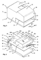
Die Figur 1 zeigt eine perspektivische Ansicht einer Frankiermaschine von
vorn oben links. Die Draufsicht in X-Richtung auf die YZ-Ebene im
kartesischen Koordinatensystem entspricht einer Ansicht der Frankiermaschine
von vorn. Die Draufsicht entgegen der Y-Richtung auf die XZ-Ebene
im kartesischen Koordinatensystem entspricht einer Ansicht der
Frankiermaschine von oben. Die Draufsicht in Z-Richtung auf die XY-Ebene
im kartesischen Koordinatensystem entspricht einer Ansicht der
Frankiermaschine von links auf deren Posteingangsseite 27. Ein
Gehäuseunterteil 1 steht mit seiner nichtgezeigten Unterseite auf der XZ-Ebene
bzw. auf einer Ebene parallel zur XZ-Ebene.
Ein abnehmbares Gehäuseoberteil 2 ist in Y-Richtung über dem
Gehäuseunterteil 1 angeordnet. Die Frankiermaschine hat eine geteilte
Frontseite. Die Frontseite 25, die Posteingangsseite 27 und die
Postausgangsseite 28 (nicht sichtbar) des Gehäuseoberteils 2 weisen
eine schlitzförmige Öffnung 21 für ein zu frankierendes Postgut auf,
welches in Z-Richtung zuführbar ist. Unterhalb der Öffnung 21 liegt ein
separat abnehmbares Gehäuseteil 29 mit einer Brieflauffläche. Die
Gehäuseoberseite weist eine zur Frontseite 25 hin geneigte Fläche 22
auf, welche geeignet ist, ein - nicht gezeigtes - Userinterface
aufzunehmen. Auf der Gehäuseoberseite 23, welche sich in X-Richtung
an die geneigte Gehäuseoberfläche 22 anschließt und welche von einer
Gehäuserückseite 26 begrenzt wird, ist eine Öffnung 24 angeordnet. Für
den Benutzer ist eine - in der Fig. 1 nicht gezeigte - Klappe als
Abdeckung vorgesehen, welche die vorgenannte Öffnung 24 abdeckt und
jederzeit geöffnet oder abgenommen werden kann. Nach Eingabe eines
unautorisierten Signals wird ein Druckmodul in eine zur Druckposition
benachbarte Position, aus der eine Tintenkartusche entfernt oder ausgetauscht
werden kann. Nur eine dazu authorisierte Person, beispielsweise
ein Servicetechniker, darf weitere Gehäuseteile abnehmen. Nach dem
Abnehmen des Gehäuseunterteils 1 und -oberteils 2 verbleibt eine
Chassisanordnung, welche eine Anzahl von in Y-Richtung über einem
Gehäuseunterteil 1 angeordneten Chassisteilen aufweist.FIG. 1 shows a perspective view of a franking machine from the top left at the front. The top view in the X direction of the YZ plane in the Cartesian coordinate system corresponds to a view of the franking machine from the front. The top view against the Y direction on the XZ plane in the Cartesian coordinate system corresponds to a view of the franking machine from above. The top view in the Z direction of the XY plane in the Cartesian coordinate system corresponds to a view of the franking machine from the left on its
A removable
Die Figur 2 zeigt eine perspektivische Ansicht einer Chassisanordnung in
gesprengter Darstellung, welche auf einer Leiterplatte 4 miteinander
verschaltet Bauelemente 142 im inneren Sicherheitsbereich mechanisch
schützt, die zur Steuereinheit der Frankiermaschine gehören und für die
eine Wärmeabfuhr ermöglicht wird, durch erzwungene Konvektion eines
Luftstromes nach aussen. Über einer zu Schutz- und Stützzwecken geformten
Unterschale 3 und der Leiterplatte 4 ist eine Oberschale 5 angeordnet,
welche zu Schutz- und Stützzwecken entsprechend geformt ist.
Die Oberschale 5 kann eine Gruppe von in einer Reihe angeordneten
äußeren Lüftungsöffnungen auf weisen, die vorzugsweise schlitzformig
am äußeren Rand eingearbeitet sind. Die Unterschale 3 besteht aus
einem zum Gehäuseunterteil 1 parallelen Abschirm- und Stützblech 31
und aus einem zur Gehäuserückseite 26 parallel abgewinkelten rückwärtigen
Abschirm- und Stützblechteil 36, welches mindestens eine Öffnung
39 zur Abführung eines erwärmten Luftstromes nach außen aufweist.
Mindestens ein Bauteil 41 ist in Y-Richtung über der Leiterplatte 4
angeordnet und durch eine Öffnung 32 im abgewinkelten rückwärtigen
Abschirm- und Stützblechteil 36 zugänglich. Das vorgenannte von außen
zugängliche Bauteil 41 ist beispielsweise ein Stecker/Dose für ein Netz-
steckerkabel. Mindestens eine Gruppe 42 von (nur teilweise sichtbaren)
Bauteilen ist in Y-Richtung über der Leiterplatte 4 angeordnet und kann
durch die darüber aufsetzbare Oberschale 5 manipulationssicher
zugedeckt werden. Eine weitere Gruppe von (nicht sichtbaren) Bauteilen
auf der Unterseite der Leiterplatte 4 wird im zusammengebauten Zustand
durch die Unterschale 3 kastenförmig zugedeckt. Die vorgenannte Gruppe
42 von Bauteilen und die weitere Gruppe von (nicht sichtbaren) Bauteilen
auf der Leiterplatten-unterseite sind damit von außen völlig unzugänglich
angeordnet und gehören zum inneren Sicher-heitsbereich. Das Abschirm-
und Stützblech 31 liegt parallel zur XZ-Ebene und hat dazu an seinen
Seitenrändern zur Posteingangsseite 27 bzw. zur Postausgangsseite 28
abgewinkelte und dabei zur XY-Ebene parallel verlaufende Seitenrandflächen
37 bzw. 38. Das rückwärtige Abschirm- und Stützblechteil 36 liegt
parallel zur YZ-Ebene und hat an den Seitenrändern zur Posteingangsseite
27 bzw. zur Postausgangsseite 28 abgewinkelte und dabei zur XY-Ebene
parallel verlaufende Seitenrandflächen 33 bzw. 34 (nicht sichtbar).
Die Unterschale 3 hat einen vom Abschirm- und Stützblech 31 und zur
Gehäusefrontseite 25 parallel abgewinkelten und dabei einen bis zur
Funktionskante parallel zur YZ-Ebene verlaufenden Frontseitenblechteil
35, welches eine zur xz-Ebene parallel verlaufende Schürze 34 aufweist.
Der Übergang zur vorgenannten Schürze 34 der Unterschale 3 ist dabei
die eine Funktionskante der Unterschale 3, welche im zusammengebauten
Zustand von der anderen Funktionskante 54 der Oberschale 5 beabstandet
ist. Die Unterschale 3 dient einerseits zur Kraftübertragung auf
das Sicherheitsgehäuseunterteil 1 und andererseits zur Verlustleistungsabführung
und zur Einhaltung des EMV-Standards. Die Chassisoberschale
5 wird an der Frontseite in Y-Richtung durch die Funktionskante 54
und parallel zur Frontseite oder durch eine zur Rückseite parallele
Funktionskante 541 in Y-Richtung begrenzt. Die Funktionskante 54 der
Chassisoberschale 5 ist umgekehrt U-förmig, d.h. ∩-förmig, gestaltet und
hat eine innere nahe der Frontseite angeordnete Seitenwand 53 und eine
äußere Frontseitenwand 55. Von der Funktionskante 54 der Chassisoberschale
5 ist die weitere ∩-förmig gestaltete Funktionskante 541 mit einer
inneren Seitenwand 531 und einer äußeren Rückseitenwand 551 in X-Richtung
beabstandet. Je eine Seitenwand 57 bzw. 58 begrenzt die
Chassisoberschale 5 poststromein- bzw poststromausgangsseitig. Eine
zum Abschirm- und Stützblech 31 parallel liegende Platte 56 teilt die innen
liegende Kavität in eine untere Kavität und eine obere Kavität 60 auf. Die
untere Kavität (nicht sichtbar) ist zur Aufnahme einer Abrechnungs- und
einer Steuerungselektronik für das Drucken vorgesehen und gehört zum
inneren Sicherheitsbereich. Die obere Kavität 60 ist zur Aufnahme einer
Andruckmechanik vorgesehen. In der Platte 56 ist eine Öffnung 561 zur
Kabeldurchführung angeordnet.
Zusätzlich kann ein Kasten 59 an der Chassisoberschale 5 angeordnet
sein, der sich beispielsweise in X-Richtung bis zur Kastenrückwand 596
erstreckt und in Z-Richtung, d.h. poststromabwärts, durch eine Kastenseitenwand
598 bzw. entgegengesetzt dazu, d.h. poststromaufwärts,
durch eine Kastenseitenwand 599 begrenzt wird. Wenn der Kasten 59,
wie gezeigt ist, einen Kastenboden 590 aufweist, dann ist im letzteren
mindestens eine Öffnung 591 für elektrische Kabel vorgesehen. Der
Kasten 59 weist beispielsweise in X-Richtung bis zur Kastenrückwand 596
eine größere Länge auf als in Z-Richtung. Die Kastenseitenwand 599 ist in
der Mitte der Länge in Z-Richtung an der außen liegenden Seitenwand
551 angeordnet, wobei alle Wände vorzugsweise eine gleiche Höhe in Y-Richtung
aufweisen.FIG. 2 shows a perspective view of a chassis arrangement in an exploded view, which mechanically protects components 142 connected to one another on a printed
In addition, a
Die Figur 3 zeigt eine perspektivische Ansicht von montierten Chassisteilen
3, 4, 5 und 6. Im zusammengebauten Zustand liegt die mit Bauteilen
der Gruppen 42 und 45 bestückte Leiterplatte 4 frontseitig auf der Schürze
34 der Unterschale 3 auf. Auf der Leiterplatte 4 stützt sich die
Chassisoberschale 5 mit deren Seitenwänden ab. Jede der Seitenwände
57 bzw. 58 sind mit Befestigungsmitteln 571 und 572 bzw. - nicht
sichtbaren - Befestigungsmitteln 581 und 582 ausgestattet, um die
Chassisoberschale 5 poststromausgangsseitig an der Chassisunterschale
3 zu befestigen. Oberhalb von deren Funktionskanten 54, 541 ist ein
Stützrahmen 6 als weiteres Chassisteil zum Abstützen der Druckmechanik
angeordnet. Der Stützrahmen 6 ist poststromein- bzw poststromausgangsseitig
durch Seitenwände 67 bzw. 68 begrenzt. Der Stützrahmen 6
hat eine Länge in Z-Richtung von der einen Seitenwand 67 zur anderen
68, die mittig durch eine Trennwand 63 in zwei rechteckförmige Kästen
aufgeteilt wird, d.h. in einen an der Poststromeingangsseite gelegenen
Kasten mit einer ersten Grundfläche und in einen an der Poststromausgangsseite
gelegenen Kasten mit einer zweiten Grundfläche, wobei
der an der Poststromeingangsseite gelegene Kasten eine kleinere Grundfläche
hat, als der an der Poststromausgangsseite gelegene Kasten. Der
an der Poststromeingangsseite gelegene Kasten wird von einer in X-Richtung
gelegene Rückseitenwand 62, der Trennwand 63, einer Frontseitenwand
64 und der Seitenwand 67 begrenzt und weist eine
Bodenplatte 61 mit der ersten Grundfläche auf. Die Trennwand 63 geht in
X-Richtung in eine Seitenwand des an der Poststromausgangsseite
gelegenen Kastens über, wobei die Seitenwand mit der Seitenwand 599
des darunter angeordneten Kastens fluchtet. Der darüber angeordnete
Kasten hat außerdem eine Frontseitenwand 65 und in X-Richtung
gelegene Rückseitenwand 66. Alle vorgenannten Wände 62, 63, 64, 65,
66, 67 bzw. 68 sind in der Höhe aufgeschnitten dargestellt, um Teile der
Druckmechanik sichtbar zu machen. Ein Poststück (nicht gezeigt) wird in
Transportrichtung Z durch eine angetriebene Transporttrommel (in Fig. 4,
5 und 6 gezeigt) transportiert, welche gegenüber mindestens einer gefederten
Gegendruckrolle 11 (in Fig. 3 und 6 gezeigt) angeordnet ist. Die
in einer fensterartigen Öffnung 291 einer Brieflauffläche 290 des separat
abnehmbaren Gehäuseteils 29 sichtbare Gegendruckrolle 11 wird nicht
angetrieben. Eine die Brieflauffläche 290 aufweisende Platte des
Gehäuseteils 29 stützt sich auf der ersten Funktionskante 54 der
Chassisoberschale 5 ab.
Ein Druckmodul 7 hat eine Schutzkappe 73 und trägt mindestens eine
auswechselbare Tintenkartusche 72, die auf einem Druckwagen 74 befestigbar
ist. Die Schutzkappe 73 hat zwei Seitenwände 733, 739 und eine
Rückseitenwand 736 sowie eine Deckenplatte 731. Letztere weist eine
Abdicht- und Führungsleiste 732 auf.
Ein gefülltes Briefkuvert wird mittels einer durch eine Öffnung 692 in einer
Bodenplatte 611 des Stützrahmens 6 ragenden Tansporttrommel während
des Druckens in Transportrichtung Z mit einer vorbestimmten Geschwindigkeit
bewegt. Der an der Poststromausgangsseite gelegene Kasten
weist parallel zur Trennwand 63 eine weitere sich in X-Richtung
erstreckende Trennwand 69 zum Begrenzen der Bodenplatte 611 in Z-Richtung
auf. Beide Trennwände 63, 69 weisen in der Nähe des
Druckposition gegenüberliegenden in Z-Richtung beabstandete Öffnungen
631, 691 für für die Transporttrommel auf. Zwischen der Trennwand
69 und der poststromausgangsseitigen Seitenwand 68 kann auf der
gleichen Ebene wie die Bodenplatte 61 eine weitere Bodenplatte 612
angeordnet sein, durch welche ein zu frankierendes Postgut, das in nicht
gezeigter Weise - in der Fig. 1 gezeigte - schlitzförmige Öffnung 21 des
Gehäuseoberteils 2 gesteckt, d.h. in Z-Richtung zugeführt wird, in seiner
Dicke ab der Brieflauffläche 290 in Y-Richtung begrenzt wird.
Die Seitenwand 57 bzw. die - nicht dargestellte - Seitenwand 58 sind mit
Bolzen 571 bzw. 581 (nicht sichtbar) als Befestigungsmittel ausgestattet.
Der Bolzen ist in einer Lageröffnung 371 bzw 381 (nicht sichtbar) der
Seitenrandflächen 37 bzw. 38 (nicht sichtbar) drehbar gelagert, um welche
die Chassisoberschale 5 drehbar ist, wenn die übrigen Befestigungsmittel
572 und 582 (nicht sichtbar) gelöst sind. Übliche Befestigungsmittel sind
Wegbrechschrauben oder verplombte Schrauben. FIG. 3 shows a perspective view of assembled
A
A filled envelope is moved by means of a transport drum protruding through an
The
Der so geschützte Sicherheitsbereich kann intern noch einen Hochsicherheitsbereich
aufweisen. Eine Kapselung des Hochsicherheitsbereiches
mittels eines weiteren Gehäuses bietet einen zusätzlichen mechanischen
Schutz. Für Frankiermaschinen wurde für einen solchen Hochsicherheitsbereich
ein Sicherheitsmodul entwickelt, das mit einer Abrecheneinheit,
mit einer kryptografischen Einheit zum Absichern der zu druckenden
Postgebührendaten und einem eigenem Sicherheitsgehäuse ausgestattet
ist.
Die Chassisunterschale 3 hat Lüftungsöffnungen 39 im rückwärtigen
Abschirm- und Stützblechteil 36 und ggf. nicht gezeigte Lüftungsöffnungen
in der Leiterplatte 4 nahe dem Bauteil 41.The security area protected in this way can still have a high security area internally. Encapsulation of the high-security area by means of another housing offers additional mechanical protection. For franking machines, a security module was developed for such a high-security area, which is equipped with an accounting unit, with a cryptographic unit for securing the postage fee data to be printed and with its own security housing.
The chassis
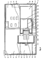
Anhand einer in der Figur 4 gezeigten Draufsicht auf eine Frankiermaschine,
die in einer XZ-Ebene geschnitten ist, wird die Lage des Druckmoduls
in Druckposition verdeutlicht. Letztere liegt im mitteleren Kasten
des Stützrahmens über dem Bereich zwischen den beiden vorgenannten
Funktionskanten 54, 541 der Chassisoberschale. Die Gehäuserückseite
26 ist in geeigneter Weise ausgebildet, einen durch die abzuführende
Verlustleistung der Bauelemente erwärmten Luftstrom abzuführen und mit
geeigneten Steckverbinderbuchsen versehen, um einsteckbare Netzanschlußkabel
und Telefon- und Interfacekabel usw. aufzunehmen. An der
Gehäuserückseite 26 des Gehäuseoberteils 2 ist ein entsprechendes
Bauelement 41 auf der Leiterplatte 4 angeordnet, wobei die Chassisunterschale
3 und die Chassisoberschale 5 einen Sicherheitsbereich auf
der Leiterplatte 4 begrenzen. Parallel zur Gehäuserückseite 26 liegt die
Rückseitenwand 66 desjenigen Kastens 63, 65, 66, 69 des Stützrahmens,
welcher zum Aufnehmen des Druckmoduls und der Transporttrommel 12
vorbestimmt ist. Letztere ist in der Nähe der Frontseite 25 angeordnet und
durch deren Drehachse geschnitten dargestellt. Die Laufflächen auf dem
Außendurchmesser der ragen zum Teil in den Kasten 62, 63, 64 und 67
mit der Bodenfläche 61 bzw. in den Kasten mit den Seitenwänden 68, 69
und mit der Bodenfläche 612, welche in der Nähe der Posteingangsseite
27 bzw. Posteingangsseite 28 angeordnet sind. Die Drehachse der
Transporttrommel 12 liegt parallel zur X-Achse. Auf der zur Rückseite 26
zugewandten Seite weist die Transporttrommel 12 eine Öffnung auf, in
welche die Kartusche 72 teilweise hineingefahren dargestellt ist. In der
Bodenplatte 611 ist im Bereich der Transporttrommel 12 eine Öffnung 692
vorgesehen, durch welche hindurch eine Kraft von der Transporttrommel
12 auf das Poststück ausgeübt wird, um das Poststück in Z-Richtung zu
transportieren. Eine für den Frankierdruck vorgesehene Öffnung ist wegen
der Kartuschenposition nicht sichtbar, kann aber so dicht an der Öffnung
692 liegen, dass beide Öffnungen aneinander grenzen. Der Kasten 63,
65, 66, 69 des Stützrahmens, welcher zum Aufnehmen des Druckmoduls
vorgesehen ist, hat eine Kabeldurchführungsöffnung 601 in der Bodenplatte
611, welche in X-Richtung von der für den Frankierdruck vorgesehenen
Öffnung entfernt ist. Diese Öffnung 601 liegt innerhalb des durch
die Schutzkappe 73 abgedeckten Bereiches. Die Schutzkappe 73 ist auf
einem Druckwagen 74 befestigt, der eine Schnittstelle 77 für mindestens
eine auswechselbare Tintenkartusche 72 trägt. Die Schutzkappe 73 hat
zwei Seitenwände 733, 739 und eine Rückseitenwand 736 sowie eine (in
Fig. 4 nicht sichtbare) Deckenplatte 731. Ein flexibles Bandkabel 76
verbindet die im Sicherheitsbereich angeordnete Steuerung mit der Druckkopfansteuerungselektronik
75 auf dem Druckwagen 74. Wenn nun der
Druckwagen 74 bis zu einem Anschlagblech 78 verfahren wird und damit
die Druckposition erreicht, dann wird die Strecke für das flexible
Bandkabel 76 von der Kabeldurchführungsöffnung 601 bis zum Anschluß
an der Druckkopfansteuerungselektronik 75 gestreckt.Using a top view of a franking machine shown in FIG. 4,
which is cut in an XZ plane, becomes the location of the print module
clarified in print position. The latter is in the middle box
of the support frame over the area between the two aforementioned
Anhand einer in der Figur 5 gezeigten Draufsicht auf eine Frankiermaschine,
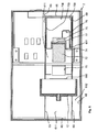
die in einer XZ-Ebene geschnitten ist, wird die Lage des Druckmoduls
in Kartuschenwechselposition verdeutlicht. Letztere liegt im
mitteleren Kasten 63, 65, 66 und 69 des Stützrahmens über dem Bereich
zwischen der vorgenannten Funktionskante 541 der Chassisoberschale
und der in Richtung zur Gehäuserückseite 26 gelegenen Kastenrückwand
66. Die Schutzkappe 73 mit Seitenwänden 733, 739 und der Rückseitenwand
736 wird mit dem Druckwagen 74 vom Anschlagblech 78 weg in X-Richtung
verfahren, wobei die Rückseitenwand 736 zur Erreichung der
Kartuschenwechselposition nahe an die Kastenrückwand 66 gebracht
wird. Dabei wird die Strecke für das flexible Bandkabel 76 von der Kabeldurchführungsöffnung
601 bis zum Anschluß an der Druckkopfansteuerungselektronik
75 gestaucht. Die Kartusche 72 ist nun von der
Öffnung 70 in der Bodenplatte 611 des mittleren Kastens des Stützrahmens
soweit entfernt, dass sie genau unter der Öffnung im Gehäuseoberteil
liegt. Die Schutzkappe 73 ist zum Umschließen des zu
schützenden veränderlichen Bereiches und dabei nicht störend für ein
Auswechseln der Kartusche 72 ausgebildet.Using a top view of a franking machine shown in FIG. 5,
which is cut in an XZ plane, becomes the location of the print module
clarified in the cartridge change position. The latter is in the
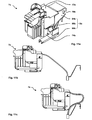
Die Figur 6 zeigt eine perspektivische Ansicht von rechts einer
aufgeschnittenen Frankiermaschine, mit dem Gehäuseoberteil 2 mit dem
Schlitz 21 zur Zuführung von Post auf der - nicht sichtbaren -
posteingangsseitigen Seitenwand und mit der postausgangsseitigen
Seitenwand 28, mit dem Gehäuseteil 29 an der Frontseite 25 des
Gehäuseoberteils 2, mit der Trennwand 15 an dem Gehäuseunterteil 1,
mit der Gruppe 51 von Öffnungen in der Frontseitenwand 55 der
Chassisoberschale 5, mit der Trennwand 63, mit der mindestens einen
auswechselbaren Tintenkartusche 72, mit der Transporttrommel 12 und
der mindestens einen Gegendruckrolle 11 in Ihrer Anordnung zueinander,
wobei letztere im Raum 60 der Chassisoberschale 5 angeordnet ist,
welcher durch die Bodenplatte 56 vom Raum 50 für die auf der
Leiterplatte 4 angeordneten Bauteile im Sicherheitsbereich getrennt ist.
Das querbeweglich zur Transportrichtung Z angeordnete Druckmodul hat
neben der mindestens einen auswechselbaren Tintenkartusche 72, die in
der Druckposition zum Teil in die Transporttrommel 73 hineinragt, einen
entsprechenden Druckwagen 74. Nähere Ausführungen dazu sind der
nicht vorveröffentlichten deutschen Patentanmeldung 100 32 855.5
entnehmbar, welche den Titel trägt: Vorrichtung zum Bedrucken eines
Druckträgers.
Von der Leiterplatte 4 durch die Bodenplatte 611 hindurch wird das
Bandkabel 76 bis zum Anschluß an Druckeransteuerungselektronik 75
geführt. Nicht nur während des Druckens, d.h. wenn der Druckwagen 74
zum Drucken mit der mindestens einen auswechselbaren Tintenkartusche
72 in die Druckposition zum Drucken durch eine Öffnung 70 der Bodenplatte
611 gebracht ist, verhindert die Schutzkappe 73 den Zugriff auf die
Daten - und Ansteuerleitungen im Bandkabel 76 bzw. Druckeransteuerungselektronik
75. Die Schutzkappe 73 ist am Druckwagen 74 befestigt
und verschließt die vorgenannte Öffnung 24 im Gehäuse, entsprechend
mehr oder weniger während der Bewegung des Druckwagens in Richtung
zur Druckposition hin oder weg. Bei jeder anderen Position, in welche der
Druckwagen gebracht werden kann, ist die vorgenannte Öffnung 24 durch
die Schutzkappe 73 also nicht/nicht vollständig verschlossen, so dass eine
Unfallgefahr besteht, dass bei Greifen in die vorgenannte Öffnung 24 per
Hand der Druckwagen 74 gerade verfahren wird. Eine Abdeckung 20 wird
deshalb erforderlich, beispielsweise eine Klappe, die aber jederzeit geöffnet
werden kann. Ein Mikroschalter 81 schaltet dann die Querbewegungsmittel
(nicht gezeigt) ab und verhindert eine Querbewegung des Druckwagens
74. Alternativ kann ein Sensor 82 eingesetzt werden, der die
Klappenposition 'offen' ermittelt, bevor die Abschaltung veranlaßt wird.FIG. 6 shows a perspective view from the right of a cut franking machine, with the
In addition to the at least one
The
Die Figur 7 zeigt eine perspektivische Ansicht einer Schutzkappe 73' nach
einer zweiten Variante. Die Schutzkappe 73' hat zwei Seitenwände 733',
739' und eine Deckenplatte 731'. Letztere weist eine Abdicht- und
Führungsleiste 732' auf. Beide Seitenwände 733', 739' sind in X-Richtung,
d.h. zur Rückseite 66 des mitteleren Kasten des Stützrahmens
hin, in der Fläche reduziert ausgebildet. Optional ist in der Schutzkappe
73', die zum Umschließen eines zu schützenden Bereiches des
lageveränderlichen Druckmoduls ausgebildet ist, eine Öffnung 730' für ein
Auswechseln mindestens einer Tintenkartusche 72 vorgesehen.FIG. 7 shows a perspective view of a protective cap 73 'according to
a second variant. The protective cap 73 'has two side walls 733',
739 'and a ceiling plate 731'. The latter has a sealing and
Guide bar 732 '. Both side walls 733 ', 739' are in the X direction,
i.e. to the
In den Figuren 8a und b werden weitere perspektivische Ansichten einer
Schutzkappe 73" nach einer dritten Variante gezeigt. Die Deckenplatte
731" ist in der Länge in X-Richtung reduziert und eine Abdicht- und
Führungsleiste entfällt. Zum Ausgleich dafür, hat die Schutzkappe 73"
nach der dritten Variante außerdem eine Rückseitenwand 736" neben
zwei Seitenwänden 733", 739" und sowie eine Deckenplatte 731". In
letzterer kann ebenfalls eine Öffnung 730" für ein Auswechseln
mindestens einer Tintenkartusche 72 vorgesehen sein. Die Rückseitenwand
736" ist jedoch gegenüber der in der Figur 3 gezeigten ersten Variante
in einer XZ-Ebene halbiert ausgebildet. Die fehlende zweite Hälfte bis
zur Bodenplatte auf der Rückseite der Schutzkappe 73" wird durch eine
Mittelplatte 737" eines Schutzkappenunterteils ergänzt bzw. abgedeckt,
welches mit zwei abgewinkelten Seitenwänden 734", 735" in der Draufsicht
ein kantiges liegendes U-Profil bildet. Von der Mittelplatte 737" ist
eine Deckfläche 738" abgewinkelt, so dass die Seitenkanten der Deckfläche
738" parallel zu den Seitenkanten der Seitenwände 734", 735" liegen.
Die Länge der von der Mittelplatte 737" abgewinkelten Seitenwände 734",
735" ist in X-Richtung annähernd doppelt so groß, wie die Länge der
Seitenwände 733", 739" in X-Richtung. Das erlaubt eine Verschiebung
des Schutzkappenunterteils zum Schutzkappenoberteil relativ zueinander.
Die Deckfläche 738" des Schutzkappenunterteils weist einen abgewinkelten
Anschlag 7381" auf, welcher eine Verschiebung des Schutzkappenunterteils
zum Schutzkappenoberteil relativ zueinander begrenzt. In der
Fig. 8a ist die Deckenplatte 731" gegenüber dem vorgenannten kantigen
unten liegenden U-Profil in X-Richtung verschoben dargestellt.FIGS. 8a and b show further perspective views of a
In der Fig. 8b ist eine perspektivische Ansicht der teleskopartig
verschiebbaren Schutzkappe 73" dargestellt, die in entgegengesetzter
Richtung, d.h. in die Druckposition, verschoben ist. Diese dritten Variante
mit teleskopartiger Verschiebung ist für Postverarbeitungsgeräte mit einer
geringen Bautiefe besonders geeignet.8b is a perspective view of the telescope
sliding
In der Fig. 9a ist eine perspektivische Ansicht von vorn oben rechts auf
das Druckmodul nach einer vierten Variante dargestellt. Das Druckmodul
7a weist eine am Druckwagen 74a befestigte Schutzkappe 73a und zwei
Tintenkartuschen 72a und 72b auf, welche vom Druckwagen 74a getragen
werden. Letzterer kann aus der Druckposition durch die Ansteuerung
der Querbewegungsmittel 17 aus der dargestellten Druckposition in eine
Tintenkartuschenwechselposition verfahren werden. Am Druckwagen 74a
ist seitlich ein Schlitten 79 befestigt mit einem Anschluß 71 für das Bandkabel
76a. Der Schlitten 79 ist in Z-Richtung am Druckwagen 74a angebracht.
Das soll aber nicht ausschließen, dass alternativ ein Schlitten auch
auf der entgegengesetzt zur Z-Richtung liegenden Seite am Druckwagen
74 angebracht werden kann. Ein Führungskanal 14 ersteckt sich seitlich
des Druckmoduls 7a in X-Richtung und dient zur Führung und zum Schutz
des Bandkabels 76a vor einem unberechtigten Zugriff auf dessen elektrische
Leitungen. In Y-Richtung, d.h. nach oben, ist der Führungskanal 14
durch eine Schutzwand 13 begrenzt. In X-Richtung ist endseitig ein Winkelstück
18 ausgebildet. Der Führungskanal 14 mit der Schutzwand 13
und dem Winkelstück 18 ist am Stützrahmen 6 befestigt (nicht gezeigt).
Das Bandkabel 76a wird in Y-Richtung vom Sicherheitsbereich zum Nichtsicherheitsbereich
geführt und verläuft nach einer Faltung parallel zur Z-Richtung.
Dabei liegt das Bandkabel 76a so gefaltet am Winkelstück 18
an, dass dessen flache Seite parallelel zur YZ-Ebene angeordnet ist.
Nach einer weiteren Faltung verläuft das Bandkabel 76a im Führungskanal
14 parallel zur X-Richtung. Das Bandkabel 76a enthält am Anschluß
71 in einer zur Z-Richtung parallelen Linie aufgereihte elektrische Leitungen
und ist mit seiner flachen Seite parallelel zur XZ-Ebene angeordnet.In Fig. 9a is a perspective view from the top right front
the printing module shown according to a fourth variant. The
Die in der Figur 9b gezeigte Seitenansicht von rechts auf den Führungskanal
des Druckmoduls 7a nach der vierten Variante zeigt einen vergrößerten
Ausschnitt des Führungskanals 14 mit dem Schlitten 79 und
dem Anschluß 71 für das Bandkabel 76a. Das Bandkabel 76a ist flexibel
und u-förmig in der XY-Ebene gebogen. Das Bandkabel 76a wird beim
Verschieben des Druckwagens innerhalb des Führungskanals 14 geführt,
wobei der u-förmige Bogen in X-Richtung oder entgegengesetzt dazu bewegt
wird. Von der Schutzwand 13 ist eine parallele Kanalwand 15 beabstandet,
wobei der Abstand D größer als der kleinste zulässige Biegeradius
des Bandkabels 76a ist.The side view shown in FIG. 9b from the right onto the guide channel
of the
Die in der Figur 9c dargestellte Draufsicht auf das Druckmodul nach der
vierten Variante verdeutlich wie einerseits die Druckkopfansteuerungselektronik
(nicht sichtbar) durch die Schutzkappe 73a und andererseits
das Bandkabel 76a durch die Schutzwand 13 gegen einen unberechtigten
Zugriff von oben geschützt ist. Zum Auswechseln von verbrauchten
Tintenkartuschen wird die Arretierung durch die Betätigung der Hebel 10a
und 10b geöffnet und dann werden neue Tintenkartuschen 72a, 72b in
den Druckwagen 74a eingesetzt, wobei die Tintendruckköpfe über die
Schnittstellen 77a und 77b mit der Druckkopfansteuerungselektronik
(nicht sichtbar) kontaktiert werden. Anschließend wird die Arretierung
durch die Hebel 10a und 10b wiederhergestellt. Nur im Bereich des
Druckmoduls 7a, wobei der Bereich während der Auswechselung
zugänglich ist, ist das Bandkabel 76a durch die Schutzwand 13 gegen
einen unberechtigten Zugriff von oben geschützt. Im hinteren Bereich des
Druckmoduls 7a wird das Winkelstück 18 so ausgebildet, dass das
Bandkabel 76a außerhalb anstatt innerhalb des Bewegungsraumes des
Druckmoduls 7a geführt wird, wobei der Bewegungsraum durch die
Wände 63, 65, 66 und 69 des Kastens innerhalb des Stützrahmens
begrenzt wird (Fig.4).The top view of the printing module shown in FIG. 9c according to FIG
fourth variant illustrates how on the one hand the printhead control electronics
(not visible) through the
In der Figur 9d ist die Seitenansicht von links auf das Druckmodul nach
der vierten Variante dargestellt, wobei sich das Druckmodul 7a in Druckposition
befindet. Der Bewegungsraum des Druckmoduls 7a ist in Z-Richtung
durch eine Führungswand 19 begrenzt, die mit der Schutzwand
13 den Führungskanal bildet. Der Druckwagen 74a trägt eine Druckkopfansteuerungselektronik
75 (gestrichelt gezeichnet, da nicht sichtbar),
welche über Schnittstellen 71a, 71b mit den Tintenkartuschen 72a, 72b
verbindbar ist und durch die Schutzkappe 73a abgedeckt wird, wobei
deren Schlitten 79 in einem Führungsschlitz 191 der Führungswand 19
verläuft und sich in X-Richtung erstreckt.In FIG. 9d, the side view of the printing module is from the left
of the fourth variant, wherein the
In der Figur 10a ist eine perspektivische Ansicht von hinten auf das
Druckmodul nach der vierten Variante dargestellt, wobei sich das
Druckmodul 7a in der Druckposition befindet.10a is a perspective view from behind of the
Pressure module shown according to the fourth variant, which is
Printing
In der Figur 10b ist eine perspektivische Ansicht von hinten auf das
Druckmodul nach der vierten Variante dargestellt, wobei sich das Druckmodul
7a in einer von der Druckposition am weitesten entfernten Position
zum Beispiel in der Kartuschenwechselposition befindet. Die Schutzkappe
73a gelang dabei in Anschlag mit der Innenwand des Winkelstücks 18.
Beide Figuren verdeutlichen die Faltungen des parallel zur Z-Richtung
geführten Bandkabels 76a, das am Winkelstück 18 anliegt. Für jede
Richtungsänderung des Bandkabels 76a ist eine Faltung erforderlich. In Figure 10b is a rear perspective view of the
Printing module shown according to the fourth variant, the
In der Figur 11a ist eine perspektivische Ansicht von vorn auf das
Druckmodul nach einer fünften Variante dargestellt, wobei sich der
Anschluß des Bandkabels 76b auf der Rückseite des Druckwagens 74b,
d.h. an der Schutzkappe 73b befindet und das Bandkabel 76b in einer zur
Z-Richtung parallelen Linie aufgereihte elektrische Leitungen enthält und
mit seiner flachen Seite parallelel zur XZ-Ebene angeordnet ist. Das
Bandkabel 76b wird dabei innerhalb des Bewegungsraumes des Druckmoduls
7b geführt, wobei der Bewegungsraum durch die Wände 63, 65,
66 und 69 des Kastens innerhalb des Stützrahmens begrenzt wird (Fig.4).
Zum Schutz der elektrische Leitungen ist das Bandkabel 76b durch eine
spezielle flexible Schutzummantelung 9b gegen einen unberechtigten
Zugriff geschützt. Die Schutzummantelung 9b besteht aus einem flachgedrückten
Schlauchstück 94b und geht an dem einen Ende in die Schutzkappe
73b über, die zur Abdeckung der Druckkopfansteuerungselektronik
dient. Das Schlauchstück 94b ist für die Aufnahme eines Bandleiters 76b
ausgebildet und weist vorzugsweise eine kraft- und formschlüssige Verbindung
mit der Schutzkappe 73b auf, die zur Zugentlastung ausgebildet
ist. Die Schutzkappe 73b ist zur Befestigung am Druckmodul 7b ausgebildet,
wobei die Mittel zur Befestigung so angeordnet sind, dass letztere
vom Zugang durch die Öffnung 24 unzugänglich sind. Die Schutzummantelung
9b führt an dem anderen Ende zu einem Steckverbinder 99b, der
beispielsweise über eine Halterung 98b am Stützrahmen 6 (Fig. 3) befestigbar
ist und der zur Zugentlastung ausgebildet ist. Das Schlauchstück
94b wird beispielsweise aus einem besonders widerstandsfähigen
Kunstoff hergestellt und ist flexibel ausgebildet. Das Schlauchstück 94b
weist eine nicht gezeigte metallische Rundum-Schirmung auf, zum
Beispiel ein flexibles innenliegendes Kupferdrahtgeflecht.In Figure 11a is a perspective view from the front of the
Printing module shown according to a fifth variant, the
Connection of the
In der Figur 11b ist die Seitenansicht von links auf das Druckmodul nach
der fünften Variante dargestellt, wobei sich das Druckmodul 7b in Druckposition
befindet.FIG. 11b shows the side view from the left of the printing module
of the fifth variant, wherein the
In der Figur 11b ist die Seitenansicht von links auf das Druckmodul nach
der fünften Variante dargestellt, wobei sich das Druckmodul 7b in
Kartuschenwechselposition befindet. FIG. 11b shows the side view from the left of the printing module
the fifth variant, wherein the
In der Figur 9a ist neben der perspektivischen Ansicht des Druckmoduls
nach der vierten Variante auch eine Verschaltung mit einem Schalter 81
dargestellt, der mindestens zeitweise in mechanischen Kontakt mit einer
entfernbaren Abdeckung (nicht gezeigt) steht. Mindestens der Schalter 81
oder ein Sensor 82 (gestrichelt gezeigt) sind über eine Ansteuerschaltung
83 mit einem Schrittmotor 16 zum Antrieb der Querbewegungsmittel 17
verbunden. Als Querbewegungsmittel 17 dient zum Beispiel eine Spindel,
welche mit dem Druckwagen zusammenwirkt, um entsprechend der Drehrichtung
der Spindel eine Querbewegung zu erzielen. Der Schalter 81 ist
einerseits mit einer Versorgungsspannung (nicht gezeigt) und andererseits
mit der Ansteuerschaltung 83 verbunden und schaltet die Versorgungsspannung
zu, wenn eine Abdeckung die Öffnung zum Auswechseln
mindestens einer Tintenkartusche veschließt. Es ist vorgesehen, dass die
Querbewegungsmittel 17 an einer Querbewegung des Druckmoduls 7
gehindert werden, nachdem eine Abdeckung (nicht gezeigt) geöffnet oder
entfernt worden ist, welche die Öffnung (in Fig.1 gezeigt) im Gehäuse 2
abdeckt.FIG. 9a shows the perspective view of the printing module
according to the fourth variant, an interconnection with a
Die Erfindung ist nicht auf die vorliegenden Ausführungsform beschränkt.
Es ist eine Vielzahl einer alternativen Chassisanordnung im Rahmen der
Ansprüche denkbar, die unterschiedlich ausgeführt sind. So können
offensichtlich weitere andere Ausführungen der Erfindung entwickelt bzw.
eingesetzt werden, die vom gleichen Grundgedanken der Erfindung
ausgehend, die von den anliegenden Ansprüchen umfaßt werden.The invention is not limited to the present embodiment.
A large number of an alternative chassis arrangement are conceivable within the scope of the claims, which are designed differently. Obviously, further other embodiments of the invention can be developed or used, starting from the same basic idea of the invention, which are encompassed by the appended claims.
Claims (16)
Applications Claiming Priority (2)
| Application Number | Priority Date | Filing Date | Title |
|---|---|---|---|
| DE10164527A DE10164527A1 (en) | 2001-12-15 | 2001-12-15 | Arrangement for protecting a print module in a mail processing device |
| DE10164527 | 2001-12-15 |
Publications (2)
| Publication Number | Publication Date |
|---|---|
| EP1320076A1 true EP1320076A1 (en) | 2003-06-18 |
| EP1320076B1 EP1320076B1 (en) | 2005-05-11 |
Family
ID=7711180
Family Applications (1)
| Application Number | Title | Priority Date | Filing Date |
|---|---|---|---|
| EP02026747A Expired - Lifetime EP1320076B1 (en) | 2001-12-15 | 2002-12-02 | Device for protecting a printing module in a mail processing apparatus |
Country Status (4)
| Country | Link |
|---|---|
| US (1) | US6789892B2 (en) |
| EP (1) | EP1320076B1 (en) |
| AT (1) | ATE295584T1 (en) |
| DE (2) | DE10164527A1 (en) |
Families Citing this family (14)
| Publication number | Priority date | Publication date | Assignee | Title |
|---|---|---|---|---|
| JP4241013B2 (en) * | 2002-11-26 | 2009-03-18 | 富士ゼロックス株式会社 | Image forming apparatus, frame structure used therefor, and manufacturing method thereof |
| JP2005007830A (en) * | 2003-06-20 | 2005-01-13 | Brother Ind Ltd | Ventilation structure of enclosure, and printing device equipped with ventilation structure of enclosure |
| KR100612019B1 (en) * | 2004-10-28 | 2006-08-11 | 삼성전자주식회사 | Thermal printer |
| KR100612020B1 (en) * | 2004-10-28 | 2006-08-11 | 삼성전자주식회사 | Thermal printer |
| US7448724B2 (en) * | 2005-12-05 | 2008-11-11 | Silverbrook Research Pty Ltd | Method of maintaining a printhead using a maintenance belt |
| US7455383B2 (en) * | 2005-12-05 | 2008-11-25 | Silverbrook Research Pty Ltd | Printhead maintenance station having maintenance belt with belt-cleaning station |
| US7445311B2 (en) * | 2005-12-05 | 2008-11-04 | Silverbrook Research Pty Ltd | Printhead maintenance station having maintenance belt |
| US7452052B2 (en) * | 2005-12-05 | 2008-11-18 | Silverbrook Research Pty Ltd | Printhead maintenance assembly having maintenance belt |
| US8164911B2 (en) | 2006-08-18 | 2012-04-24 | Delphi Technologies, Inc. | Lightweight electronic device for automotive applications and method |
| DE102008009947A1 (en) * | 2008-02-20 | 2009-08-27 | Knorr-Bremse Systeme für Nutzfahrzeuge GmbH | Device for receiving an electrical / electronic component and corresponding mounting method and cover for such a device |
| DE202012005904U1 (en) * | 2012-06-15 | 2012-07-16 | Francotyp-Postalia Gmbh | franking machine |
| TWI498228B (en) * | 2012-07-09 | 2015-09-01 | Kinpo Elect Inc | Inkpot limiting device and multifunctional printer using the same |
| EP3180195B1 (en) | 2014-08-13 | 2020-06-24 | Durst Phototechnik AG | Printing module with front interchangeable head |
| JP7109944B2 (en) * | 2018-03-13 | 2022-08-01 | キヤノン株式会社 | recording device |
Citations (3)
| Publication number | Priority date | Publication date | Assignee | Title |
|---|---|---|---|---|
| EP0881086A2 (en) * | 1997-05-28 | 1998-12-02 | Neopost Limited | Secure printing apparatus with removable print head |
| EP1095780A1 (en) * | 1999-10-29 | 2001-05-02 | Neopost Limited | Digital print head |
| US6238038B1 (en) * | 1997-12-30 | 2001-05-29 | Neopost Industrie | Secure digital postage print module |
Family Cites Families (6)
| Publication number | Priority date | Publication date | Assignee | Title |
|---|---|---|---|---|
| GB2169875B (en) * | 1985-01-19 | 1988-09-14 | Francotyp Postalia Gmbh | Improvements in ribbon cassettes |
| GB9709049D0 (en) | 1997-05-02 | 1997-06-25 | Neopost Ltd | Postage meter with removable print head |
| GB9709051D0 (en) | 1997-05-02 | 1997-06-25 | Neopost Ltd | Postage meter with removable print head |
| DE19748954A1 (en) * | 1997-10-29 | 1999-05-06 | Francotyp Postalia Gmbh | Producing security markings in franking machine |
| US6024429A (en) * | 1997-10-30 | 2000-02-15 | Pitney Bowes Inc. | Mailing machine including ink jet printing having ink availability checking |
| DE10021250A1 (en) * | 2000-04-22 | 2001-10-25 | Francotyp Postalia Gmbh | Arrangement for mail item detection |
-
2001
- 2001-12-15 DE DE10164527A patent/DE10164527A1/en not_active Withdrawn
-
2002
- 2002-12-02 AT AT02026747T patent/ATE295584T1/en active
- 2002-12-02 DE DE50203065T patent/DE50203065D1/en not_active Expired - Lifetime
- 2002-12-02 EP EP02026747A patent/EP1320076B1/en not_active Expired - Lifetime
- 2002-12-16 US US10/320,952 patent/US6789892B2/en not_active Expired - Fee Related
Patent Citations (3)
| Publication number | Priority date | Publication date | Assignee | Title |
|---|---|---|---|---|
| EP0881086A2 (en) * | 1997-05-28 | 1998-12-02 | Neopost Limited | Secure printing apparatus with removable print head |
| US6238038B1 (en) * | 1997-12-30 | 2001-05-29 | Neopost Industrie | Secure digital postage print module |
| EP1095780A1 (en) * | 1999-10-29 | 2001-05-02 | Neopost Limited | Digital print head |
Also Published As
| Publication number | Publication date |
|---|---|
| US20030112315A1 (en) | 2003-06-19 |
| DE50203065D1 (en) | 2005-06-16 |
| ATE295584T1 (en) | 2005-05-15 |
| EP1320076B1 (en) | 2005-05-11 |
| DE10164527A1 (en) | 2003-07-10 |
| US6789892B2 (en) | 2004-09-14 |
Similar Documents
| Publication | Publication Date | Title |
|---|---|---|
| EP1320076B1 (en) | Device for protecting a printing module in a mail processing apparatus | |
| EP0147730B1 (en) | Document encoder | |
| DE3729342A1 (en) | SECURITY PRINTER FOR A VALUE PRINTING SYSTEM | |
| EP2073173B1 (en) | Device for exchanging ink cartridges | |
| DE69829911T2 (en) | Secure pusher with a removable printhead | |
| EP1300807B1 (en) | Method and device for opening a security housing | |
| DE202010015354U1 (en) | Modular printer device with a removable box-shaped assembly | |
| DE60020649T2 (en) | Carriage with protective cover for the electrical connection contacts and recording device | |
| EP2674921B1 (en) | Franking machine and method for servicing the same | |
| DE3211757C2 (en) | Housing cover for printing devices operated with either continuous or single paper | |
| DE10164526A1 (en) | security chassis | |
| EP1615174A2 (en) | Communication system in an apparatus | |
| DE3407633A1 (en) | ADDITIONAL PRINTING DEVICE FOR A franking machine | |
| EP1103927A2 (en) | Tachograph with a flat, mountable case | |
| EP1643456B9 (en) | Cassette compartment with state detection for a franking machine | |
| DE202018102465U1 (en) | Good processing device with an inkjet printhead | |
| DE10043023A1 (en) | Security device to protect unauthorized persons from removing an electrical connection | |
| DE3636353C1 (en) | Sealable housing for taximeter printers and taximeter data storage modules | |
| DE10149210A1 (en) | Arrangement for unlocking and opening of a security housing, especially a franking machine housing, whereby a print module is first moved out of the way to allow mechanical release of the security housing | |
| DE19511511A1 (en) | Air=bag esp. for vehicle door | |
| EP0965904B1 (en) | Carrying case with integrated office devices | |
| EP1575000A1 (en) | Tachograph with exchangeable printer | |
| EP0961236A2 (en) | Apparatus for printing mailpieces | |
| DE19925681A1 (en) | Arrangement for printing postal items has arrival area with printer for stacked or individual arrival and printing of postal items, transport area with extraction device for serially passing items | |
| DE10051768A1 (en) | Mail franking and printing machine has multiple print modules that move orthogonally with respect to the direction of mail transport and can print multiple rows with different colors and graphics with a high throughput rate |
Legal Events
| Date | Code | Title | Description |
|---|---|---|---|
| PUAI | Public reference made under article 153(3) epc to a published international application that has entered the european phase |
Free format text: ORIGINAL CODE: 0009012 |
|
| AK | Designated contracting states |
Designated state(s): AT BE BG CH CY CZ DE DK EE ES FI FR GB GR IE IT LI LU MC NL PT SE SI SK TR |
|
| AX | Request for extension of the european patent |
Extension state: AL LT LV MK RO |
|
| 17P | Request for examination filed |
Effective date: 20030709 |
|
| AKX | Designation fees paid |
Designated state(s): AT BE BG CH CY CZ DE DK EE ES FI FR GB GR IE IT LI LU MC NL PT SE SI SK TR |
|
| GRAP | Despatch of communication of intention to grant a patent |
Free format text: ORIGINAL CODE: EPIDOSNIGR1 |
|
| GRAS | Grant fee paid |
Free format text: ORIGINAL CODE: EPIDOSNIGR3 |
|
| GRAA | (expected) grant |
Free format text: ORIGINAL CODE: 0009210 |
|
| AK | Designated contracting states |
Kind code of ref document: B1 Designated state(s): AT BE BG CH CY CZ DE DK EE ES FI FR GB GR IE IT LI LU MC NL PT SE SI SK TR |
|
| PG25 | Lapsed in a contracting state [announced via postgrant information from national office to epo] |
Ref country code: TR Free format text: LAPSE BECAUSE OF FAILURE TO SUBMIT A TRANSLATION OF THE DESCRIPTION OR TO PAY THE FEE WITHIN THE PRESCRIBED TIME-LIMIT Effective date: 20050511 Ref country code: SK Free format text: LAPSE BECAUSE OF FAILURE TO SUBMIT A TRANSLATION OF THE DESCRIPTION OR TO PAY THE FEE WITHIN THE PRESCRIBED TIME-LIMIT Effective date: 20050511 Ref country code: IE Free format text: LAPSE BECAUSE OF FAILURE TO SUBMIT A TRANSLATION OF THE DESCRIPTION OR TO PAY THE FEE WITHIN THE PRESCRIBED TIME-LIMIT Effective date: 20050511 Ref country code: FI Free format text: LAPSE BECAUSE OF FAILURE TO SUBMIT A TRANSLATION OF THE DESCRIPTION OR TO PAY THE FEE WITHIN THE PRESCRIBED TIME-LIMIT Effective date: 20050511 Ref country code: SI Free format text: LAPSE BECAUSE OF FAILURE TO SUBMIT A TRANSLATION OF THE DESCRIPTION OR TO PAY THE FEE WITHIN THE PRESCRIBED TIME-LIMIT Effective date: 20050511 Ref country code: CZ Free format text: LAPSE BECAUSE OF FAILURE TO SUBMIT A TRANSLATION OF THE DESCRIPTION OR TO PAY THE FEE WITHIN THE PRESCRIBED TIME-LIMIT Effective date: 20050511 Ref country code: EE Free format text: LAPSE BECAUSE OF FAILURE TO SUBMIT A TRANSLATION OF THE DESCRIPTION OR TO PAY THE FEE WITHIN THE PRESCRIBED TIME-LIMIT Effective date: 20050511 |
|
| REG | Reference to a national code |
Ref country code: GB Ref legal event code: FG4D Free format text: NOT ENGLISH |
|
| REG | Reference to a national code |
Ref country code: CH Ref legal event code: NV Representative=s name: ROTTMANN, ZIMMERMANN + PARTNER AG Ref country code: CH Ref legal event code: EP |
|
| REG | Reference to a national code |
Ref country code: IE Ref legal event code: FG4D Free format text: LANGUAGE OF EP DOCUMENT: GERMAN |
|
| REF | Corresponds to: |
Ref document number: 50203065 Country of ref document: DE Date of ref document: 20050616 Kind code of ref document: P |
|
| PG25 | Lapsed in a contracting state [announced via postgrant information from national office to epo] |
Ref country code: GR Free format text: LAPSE BECAUSE OF FAILURE TO SUBMIT A TRANSLATION OF THE DESCRIPTION OR TO PAY THE FEE WITHIN THE PRESCRIBED TIME-LIMIT Effective date: 20050811 Ref country code: BG Free format text: LAPSE BECAUSE OF FAILURE TO SUBMIT A TRANSLATION OF THE DESCRIPTION OR TO PAY THE FEE WITHIN THE PRESCRIBED TIME-LIMIT Effective date: 20050811 Ref country code: SE Free format text: LAPSE BECAUSE OF FAILURE TO SUBMIT A TRANSLATION OF THE DESCRIPTION OR TO PAY THE FEE WITHIN THE PRESCRIBED TIME-LIMIT Effective date: 20050811 Ref country code: DK Free format text: LAPSE BECAUSE OF FAILURE TO SUBMIT A TRANSLATION OF THE DESCRIPTION OR TO PAY THE FEE WITHIN THE PRESCRIBED TIME-LIMIT Effective date: 20050811 |
|
| PG25 | Lapsed in a contracting state [announced via postgrant information from national office to epo] |
Ref country code: ES Free format text: LAPSE BECAUSE OF FAILURE TO SUBMIT A TRANSLATION OF THE DESCRIPTION OR TO PAY THE FEE WITHIN THE PRESCRIBED TIME-LIMIT Effective date: 20050822 |
|
| GBT | Gb: translation of ep patent filed (gb section 77(6)(a)/1977) |
Effective date: 20050902 |
|
| PG25 | Lapsed in a contracting state [announced via postgrant information from national office to epo] |
Ref country code: PT Free format text: LAPSE BECAUSE OF FAILURE TO SUBMIT A TRANSLATION OF THE DESCRIPTION OR TO PAY THE FEE WITHIN THE PRESCRIBED TIME-LIMIT Effective date: 20051019 |
|
| PG25 | Lapsed in a contracting state [announced via postgrant information from national office to epo] |
Ref country code: CY Free format text: LAPSE BECAUSE OF FAILURE TO SUBMIT A TRANSLATION OF THE DESCRIPTION OR TO PAY THE FEE WITHIN THE PRESCRIBED TIME-LIMIT Effective date: 20051202 |
|
| REG | Reference to a national code |
Ref country code: IE Ref legal event code: FD4D |
|
| PG25 | Lapsed in a contracting state [announced via postgrant information from national office to epo] |
Ref country code: LU Free format text: LAPSE BECAUSE OF NON-PAYMENT OF DUE FEES Effective date: 20051231 Ref country code: MC Free format text: LAPSE BECAUSE OF NON-PAYMENT OF DUE FEES Effective date: 20051231 Ref country code: BE Free format text: LAPSE BECAUSE OF NON-PAYMENT OF DUE FEES Effective date: 20051231 |
|
| RAP2 | Party data changed (patent owner data changed or rights of a patent transferred) |
Owner name: FRANCOTYP-POSTALIA GMBH |
|
| NLT2 | Nl: modifications (of names), taken from the european patent patent bulletin |
Owner name: FRANCOTYP-POSTALIA GMBH Effective date: 20060104 |
|
| PLBE | No opposition filed within time limit |
Free format text: ORIGINAL CODE: 0009261 |
|
| STAA | Information on the status of an ep patent application or granted ep patent |
Free format text: STATUS: NO OPPOSITION FILED WITHIN TIME LIMIT |
|
| ET | Fr: translation filed | ||
| 26N | No opposition filed |
Effective date: 20060214 |
|
| BERE | Be: lapsed |
Owner name: FRANCOTYP-POSTALIA A.G. & CO. KG Effective date: 20051231 |
|
| REG | Reference to a national code |
Ref country code: CH Ref legal event code: PFA Owner name: FRANCOTYP-POSTALIA AG & CO. KG Free format text: FRANCOTYP-POSTALIA AG & CO. KG#TRIFTWEG 21-26#16547 BIRKENWERDER (DE) -TRANSFER TO- FRANCOTYP-POSTALIA AG & CO. KG#TRIFTWEG 21-26#16547 BIRKENWERDER (DE) |
|
| REG | Reference to a national code |
Ref country code: GB Ref legal event code: 746 Effective date: 20130319 |
|
| REG | Reference to a national code |
Ref country code: DE Ref legal event code: R081 Ref document number: 50203065 Country of ref document: DE Owner name: FRANCOTYP-POSTALIA GMBH, DE Free format text: FORMER OWNER: FRANCOTYP-POSTALIA AG & CO. KG, 16547 BIRKENWERDER, DE Effective date: 20130319 |
|
| REG | Reference to a national code |
Ref country code: GB Ref legal event code: 732E Free format text: REGISTERED BETWEEN 20130516 AND 20130522 |
|
| REG | Reference to a national code |
Ref country code: GB Ref legal event code: 732E Free format text: REGISTERED BETWEEN 20130523 AND 20130529 |
|
| REG | Reference to a national code |
Ref country code: DE Ref legal event code: R084 Ref document number: 50203065 Country of ref document: DE Effective date: 20130314 |
|
| PGFP | Annual fee paid to national office [announced via postgrant information from national office to epo] |
Ref country code: DE Payment date: 20141017 Year of fee payment: 13 |
|
| REG | Reference to a national code |
Ref country code: DE Ref legal event code: R081 Ref document number: 50203065 Country of ref document: DE Owner name: FRANCOTYP-POSTALIA GMBH, DE Free format text: FORMER OWNER: FRANCOTYP-POSTALIA GMBH, 16547 BIRKENWERDER, DE Effective date: 20150330 |
|
| REG | Reference to a national code |
Ref country code: FR Ref legal event code: PLFP Year of fee payment: 14 |
|
| PGFP | Annual fee paid to national office [announced via postgrant information from national office to epo] |
Ref country code: GB Payment date: 20151221 Year of fee payment: 14 Ref country code: CH Payment date: 20151221 Year of fee payment: 14 |
|
| PGFP | Annual fee paid to national office [announced via postgrant information from national office to epo] |
Ref country code: AT Payment date: 20151222 Year of fee payment: 14 Ref country code: NL Payment date: 20151221 Year of fee payment: 14 Ref country code: FR Payment date: 20151221 Year of fee payment: 14 |
|
| PGFP | Annual fee paid to national office [announced via postgrant information from national office to epo] |
Ref country code: IT Payment date: 20151228 Year of fee payment: 14 |
|
| REG | Reference to a national code |
Ref country code: DE Ref legal event code: R119 Ref document number: 50203065 Country of ref document: DE |
|
| PG25 | Lapsed in a contracting state [announced via postgrant information from national office to epo] |
Ref country code: DE Free format text: LAPSE BECAUSE OF NON-PAYMENT OF DUE FEES Effective date: 20160701 |
|
| REG | Reference to a national code |
Ref country code: CH Ref legal event code: PCAR Free format text: NEW ADDRESS: GARTENSTRASSE 28 A, 5400 BADEN (CH) |
|
| PG25 | Lapsed in a contracting state [announced via postgrant information from national office to epo] |
Ref country code: IT Free format text: LAPSE BECAUSE OF NON-PAYMENT OF DUE FEES Effective date: 20161202 |
|
| REG | Reference to a national code |
Ref country code: CH Ref legal event code: PL |
|
| REG | Reference to a national code |
Ref country code: NL Ref legal event code: MM Effective date: 20170101 |
|
| REG | Reference to a national code |
Ref country code: AT Ref legal event code: MM01 Ref document number: 295584 Country of ref document: AT Kind code of ref document: T Effective date: 20161202 |
|
| GBPC | Gb: european patent ceased through non-payment of renewal fee |
Effective date: 20161202 |
|
| PG25 | Lapsed in a contracting state [announced via postgrant information from national office to epo] |
Ref country code: NL Free format text: LAPSE BECAUSE OF NON-PAYMENT OF DUE FEES Effective date: 20170101 |
|
| REG | Reference to a national code |
Ref country code: FR Ref legal event code: ST Effective date: 20170831 |
|
| PG25 | Lapsed in a contracting state [announced via postgrant information from national office to epo] |
Ref country code: CH Free format text: LAPSE BECAUSE OF NON-PAYMENT OF DUE FEES Effective date: 20161231 Ref country code: AT Free format text: LAPSE BECAUSE OF NON-PAYMENT OF DUE FEES Effective date: 20161202 Ref country code: LI Free format text: LAPSE BECAUSE OF NON-PAYMENT OF DUE FEES Effective date: 20161231 Ref country code: FR Free format text: LAPSE BECAUSE OF NON-PAYMENT OF DUE FEES Effective date: 20170102 |
|
| PG25 | Lapsed in a contracting state [announced via postgrant information from national office to epo] |
Ref country code: GB Free format text: LAPSE BECAUSE OF NON-PAYMENT OF DUE FEES Effective date: 20161202 |