EP1319779A1 - Abschliessbare Bolzenverriegelung für Schiebetüren - Google Patents
Abschliessbare Bolzenverriegelung für Schiebetüren Download PDFInfo
- Publication number
- EP1319779A1 EP1319779A1 EP02024223A EP02024223A EP1319779A1 EP 1319779 A1 EP1319779 A1 EP 1319779A1 EP 02024223 A EP02024223 A EP 02024223A EP 02024223 A EP02024223 A EP 02024223A EP 1319779 A1 EP1319779 A1 EP 1319779A1
- Authority
- EP
- European Patent Office
- Prior art keywords
- bolt
- housing
- stop
- locking lug
- cylindrical
- Prior art date
- Legal status (The legal status is an assumption and is not a legal conclusion. Google has not performed a legal analysis and makes no representation as to the accuracy of the status listed.)
- Granted
Links
- 230000008878 coupling Effects 0.000 description 2
- 238000010168 coupling process Methods 0.000 description 2
- 238000005859 coupling reaction Methods 0.000 description 2
- 238000004519 manufacturing process Methods 0.000 description 2
- 230000015572 biosynthetic process Effects 0.000 description 1
- 238000003801 milling Methods 0.000 description 1
Images


Classifications
-
- E—FIXED CONSTRUCTIONS
- E05—LOCKS; KEYS; WINDOW OR DOOR FITTINGS; SAFES
- E05B—LOCKS; ACCESSORIES THEREFOR; HANDCUFFS
- E05B65/00—Locks or fastenings for special use
- E05B65/08—Locks or fastenings for special use for sliding wings
- E05B65/0864—Locks or fastenings for special use for sliding wings the bolts sliding perpendicular to the wings
-
- E—FIXED CONSTRUCTIONS
- E05—LOCKS; KEYS; WINDOW OR DOOR FITTINGS; SAFES
- E05C—BOLTS OR FASTENING DEVICES FOR WINGS, SPECIALLY FOR DOORS OR WINDOWS
- E05C5/00—Fastening devices with bolts moving otherwise than only rectilinearly and only pivotally or rotatively
- E05C5/02—Fastening devices with bolts moving otherwise than only rectilinearly and only pivotally or rotatively both moving axially and turning about their axis to secure the wing
-
- E—FIXED CONSTRUCTIONS
- E05—LOCKS; KEYS; WINDOW OR DOOR FITTINGS; SAFES
- E05B—LOCKS; ACCESSORIES THEREFOR; HANDCUFFS
- E05B63/00—Locks or fastenings with special structural characteristics
- E05B63/0065—Operating modes; Transformable to different operating modes
- E05B63/0069—Override systems, e.g. allowing opening from inside without the key, even when locked from outside
Definitions
- the invention relates to a lockable bolt lock for sliding doors a cylindrical housing fixed in the door leaf, one in this housing slidably mounted cylindrical bolt and one in this bolt housed profile cylinder, its locking nose in tangential recesses of the housing can be immersed.
- a lockable bolt lock for locking sliding doors has become known, in which the housing for the displaceable bolt has the following structure:
- a hollow cylindrical body preferably made of plastic, has a flange at its front end which is supported on the door leaf.
- the rear end has an external thread onto which a flange ring can be screwed.
- the inner surface of the hollow cylinder has, among other things, two tangentially milled grooves into which the locking lug of the profile cylinder can dip. The depth of these grooves is smaller than the wall thickness of the hollow cylinder. So they do not penetrate the outer jacket.
- An axially parallel elongated hole is also milled into the outer jacket of the hollow cylinder, which receives cylinder head screws.
- the invention has for its object to provide a bolt lock that is easier to use and foolproof, but above all is cheaper to manufacture.
- This object is achieved in that the cylinder jacket of the housing has two tangential recesses offset by the stroke of the bolt, in each of which an axially aligned boundary surface serves as a stop for the locking nose, the withdrawal position of the key corresponding to this stop.
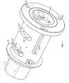
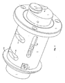
- Fig. 1 denotes a cylindrical bolt which can slide in a hollow cylindrical housing 2.
- This housing carries at the left end a flange 2a, which rests on the outside of a door leaf, not shown.
- a flange ring 3 with an internal thread is provided on the inside of the door, to which a corresponding external thread of the housing 2 is assigned.
- the housing 2 is secured against rotation by a plate 4.
- the flange ring 3 has fastening bores 3a, 3b and 3c. 4, a profile cylinder 5 is accommodated, the locking lug 9 of which rests in a tangential recess 2b of the housing 2.
- the bolt 1 is therefore locked in the illustrated left end position.
- the locking lug 9 dips down and releases the bolt 1.
- the path of the bolt to the right is limited by an elongated hole 2d in the housing 2 and a cylinder head screw 6 in the bolt. Elongated hole and cylinder head screw also prevent the bolt 1 from rotating in the housing 2.
- the locking lug 9 then appears in the tangential recess 2c, where it abuts the stop 2c1.
- a rotary knob 7 mounted in the bolt 1 is used with a radial pin 8.
- This rotary knob is constantly connected to the locking lug 9 via a concealed shaft, so that the escape route is accessible from the inside to the outside at all times.
- the profile cylinder 5 differs from conventional cylinder locks in such a way that its shaft, which is locked by pins and can be unlocked by the key, is not constantly connected to the locking lug 9.
- the shaft and the locking lug are normally uncoupled and are only connected to each other by inserting the key. If the locking lug 9 is in the locked position, the coupling occurs immediately when the key is inserted. If the locking lug has previously been brought into another position via the rotary knob 7, the coupling audibly engages when the key is turned.
- Fig. 4 shows the bolt lock from a different perspective.
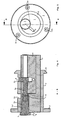
- Fig. 5 shows the top view from the rear.
- the bolt 1 rests in the hollow cylindrical housing 2 which is screwed to the flange ring 3.
- the Bores 3a, 3b and 3c receive countersunk screws.
- the knob 7 with the Pin 8 is used to open the door from the inside.
- Fig. 6 shows a longitudinal section along the line AB in Fig. 5.
- the cylindrical Bolt 1 has various recesses in which the profile cylinder 5 and Shaft of the rotary knob 7 are housed.
- the locking nose 9 sits on one Shaft 9a, which is connected via a pin 10 to the shaft 7a of the rotary knob 7 is.
- a groove 7a1 serves to hold the shaft 7a in the bore of the bolt 1.
- the special profile cylinder 5 with the coupled locking lug 9 and the shaft 9a is the commercial state of the art. The formation of the clutch is not shown.
- the manufacture of the described device is particularly simple and inexpensive, because all of the cutouts on the housing 2 can be produced in a single clamping of the workpiece. It is even possible to get by with a single cylindrical milling cutter if the diameter of the head of the screw 6 is adapted to the width of the locking lug 9.
- the bolt lock disclosed here is intended to be used in sliding doors of any design in the private or commercial sector.
Landscapes
- Engineering & Computer Science (AREA)
- Mechanical Engineering (AREA)
- Lock And Its Accessories (AREA)
Abstract
Description
Die innere Fläche des Hohlzylinders weist unter anderem zwei tangential ausgefräste Nuten auf, in die die Schließnase des Profilzylinders eintauchen kann. Die Tiefe dieser Nuten ist kleiner als die Wandstärke des Hohlzylinders. Sie durchdringen also nicht den Außenmantel.
In den Außenmantel des Hohlzylinders ist ferner ein achsparalleles Langloch eingefräst, das Zylinderkopfschrauben aufnimmt. Diese Schrauben werden in Gewindelöcher des Bolzens eingesetzt und haben die Aufgabe, die Längsbewegung des Bolzens im Gehäuse zu begrenzen und eine Verdrehung des Bolzens zu verhindern. Zusätzlich sind in dem Langloch federnde Nocken vorgesehen, die vor dem Erreichen der Endstellungen des Bolzens von den Schraubenköpfen überwunden werden müssen. Somit ist auch bei nicht eingerasteter Schließnase ein gewisser Zug oder Druck erforderlich, um den Bolzen von der einen in die andere Endposition zu bringen.
Bei der Handhabung erweist es sich als störend, dass man den eingeschobenen Bolzen nur durch kräftiges Ziehen am Schlüssel aus der Verriegelungsstellung herausbewegen kann. Auch wird die Bedienung dadurch erschwert, dass man den Schlüssel zum Entsperren sowohl nach links als auch nach rechts drehen kann.
Dies hat nämlich zur Folge, dass man die Mittelstellung, in der der Schlüssel abgezogen werden kann, ertasten muss.
Diese Aufgabe wird dadurch gelöst, dass der Zylindermantel des Gehäuses zwei um den Hub des Bolzens versetzte tangentiale Aussparungen aufweist, bei denen jeweils eine axial ausgerichtete Begrenzungsfläche als Anschlag für die Schließnase dient, wobei die Abziehposition des Schlüssels mit diesem Anschlag übereinstimmt.
- Fig. 1
- zeigt perspektivisch die Bolzenverriegelung in der entsperrten Stellung,
- Fig. 2
- eine Mittelstellung des Bolzens,
- Fig. 3
- die Verriegelungsposition,
- Fig. 4
- eine andere Ansicht mit zurückgezogenem Bolzen,
- Fig. 5
- die Draufsicht von der Rückseite,
- Fig. 6
- einen Längsschnitt entlang der Ebene A-B in Fig. 5
Das Gehäuse 2 wird durch ein Plättchen 4 gegen Verdrehung gesichert. Der Flanschring 3 weist Befestigungsbohrungen 3a, 3b und 3c auf. In dem Bolzen 1 ist - wie Fig. 4 zeigt - ein Profilzylinder 5 untergebracht, dessen Schließnase 9 in einer tangentialen Aussparung 2b des Gehäuses 2 ruht. Der Bolzen 1 ist daher in der dargestellten linken Endposition arretiert.
Wenn man den Schlüssel in den verdeckten Profilzylinder 5 einführt und um mindestens 90° nach rechts dreht, taucht die Schließnase 9 nach unten weg und gibt den Bolzen 1 frei. Der Weg des Bolzens nach rechts wird durch ein Langloch 2d im Gehäuse 2 und eine Zylinderkopfschraube 6 im Bolzen begrenzt. Langloch und Zylinderkopfschraube verhindern zugleich eine Verdrehung des Bolzens 1 im Gehäuse 2.
Nach dem Einschieben des Bolzens dreht man den Schlüssel nach links und zieht ab. Dabei taucht dann die Schließnase 9 in der tangentialen Aussparung 2c auf, wo sie gegen den Anschlag 2c1 stößt.
Zur Entriegelung der Tür von innen dient ein im Bolzen 1 gelagerter Drehknopf 7 mit einem radialen Stift 8. Dieser Drehknopf ist über eine verdeckte Welle ständig mit der Schließnase 9 verbunden, so dass der Fluchtweg von innen nach außen jederzeit zugänglich ist. Dabei ist aber der Profilzylinder 5 abweichend von üblichen Zylinderschlössern so beschaffen, dass seine durch Stifte gesperrte und durch den Schlüssel entsperrbare Welle nicht ständig mit der Schließnase 9 verbunden ist. Die Welle und die Schließnase sind normalerweise entkuppelt und werden erst durch das Einführen des Schlüssels miteinander verbunden.
Wenn die Schließnase 9 in der Sperrstellung steht, tritt das Einkuppeln beim Einstecken des Schlüssels unmittelbar ein. Sollte vorher die Schließnase über den Drehknopf 7 in eine andere Position gebracht worden sein, so rastet die Kupplung hörbar beim Drehen des Schlüssels ein.
Die hier offenbarte Bolzenverriegelung ist dazu bestimmt, in beliebig aufgebaute Schiebetüren im privaten oder gewerblichen Bereich eingesetzt zu werden.
- 1
- Bolzen
- 2
- Gehäuse
- 2a
- Flansch
- 2b, 2c
- Aussparungen
- 2b1, 2c1
- axiale Anschlagflächen
- 2d
- Langloch
- 3
- Flanschring
- 3a, 3b, 3c
- Befestigungsbohrungen
- 4
- Plättchen
- 5
- Profilzylinder
- 6
- Zylinderkopfschraube
- 7
- Drehknopf
- 7a
- Welle
- 7a1
- Nut
- 8
- Stift
- 9
- Schließnase
- 9a
- Welle
- 10
- Stift
Claims (3)
- Abschließbare Bolzenverriegelung für Schiebetüren mit einem im Türblatt befestigten zylindrischen Gehäuse, einem in diesem Gehäuse verschiebbar gelagerten zylindrischen Bolzen und einem in diesem Bolzen untergebrachten Profilzylinder, dessen Schließnase in tangentiale Aussparungen des Gehäuses eintauchen kann,
dadurch gekennzeichnet, dass der Zylindermantel des Gehäuses (2) zwei um den Hub des Bolzens (1) versetzte tangentiale Aussparungen (2b, 2c) aufweist, bei denen jeweils eine axial ausgerichtete Begrenzungsfläche (2b1, 2c1) als Anschlag für die Schließnase (9) dient, wobei die Abziehposition des Schlüssels mit diesem Anschlag übereinstimmt. - Abschließbare Bolzenverriegelung nach Anspruch 1,
dadurch gekennzeichnet, dass die tangentialen Aussparungen (2b, 2c) des Zylindermantels in einer einzigen Aufspannung aus dem Gehäuse herausgefräst sind. - Abschließbare Bolzenverriegelung nach Anspruch 2,
dadurch gekennzeichnet, dass auch das Langloch (2d) für die Bewegungsbegrenzung in dieser Aufspannung ausgefräst ist.
Applications Claiming Priority (2)
| Application Number | Priority Date | Filing Date | Title |
|---|---|---|---|
| DE20120235U DE20120235U1 (de) | 2001-12-14 | 2001-12-14 | Abschließbare Bolzenverriegelung für Schiebetüren |
| DE20120235U | 2001-12-14 |
Publications (2)
| Publication Number | Publication Date |
|---|---|
| EP1319779A1 true EP1319779A1 (de) | 2003-06-18 |
| EP1319779B1 EP1319779B1 (de) | 2007-12-12 |
Family
ID=7965150
Family Applications (1)
| Application Number | Title | Priority Date | Filing Date |
|---|---|---|---|
| EP02024223A Expired - Lifetime EP1319779B1 (de) | 2001-12-14 | 2002-10-31 | Abschliessbare Bolzenverriegelung für Schiebetüren |
Country Status (5)
| Country | Link |
|---|---|
| EP (1) | EP1319779B1 (de) |
| AT (1) | ATE380914T1 (de) |
| DE (2) | DE20120235U1 (de) |
| DK (1) | DK1319779T3 (de) |
| ES (1) | ES2298320T3 (de) |
Cited By (3)
| Publication number | Priority date | Publication date | Assignee | Title |
|---|---|---|---|---|
| GB2435669A (en) * | 2006-03-02 | 2007-09-05 | Martin Charles Wright | Lock device for retractable security post |
| DE102007004467A1 (de) | 2007-01-30 | 2008-07-31 | Rahrbach Gmbh | Bolzenschließung mit verbesserter Notentriegelung |
| DE102008027081A1 (de) | 2008-06-05 | 2009-12-10 | Rahrbach Gmbh | Bolzenschließung mit verbesserter Notentriegelung |
Families Citing this family (3)
| Publication number | Priority date | Publication date | Assignee | Title |
|---|---|---|---|---|
| DE202005019410U1 (de) | 2005-12-13 | 2007-04-19 | Coolit Isoliersysteme Gmbh | Schlüsselbetätigbare Blockiereinrichtung |
| DE202006012565U1 (de) * | 2006-08-16 | 2006-10-19 | Steinbach & Vollmann Gmbh & Co. Kg | Verschließbare Bolzenverriegelung für Schiebetüren |
| RU2646202C1 (ru) * | 2016-11-14 | 2018-03-01 | Общество с ограниченной ответственностью "Инженерно-технический центр "ПРОМИКС" | Электромеханический замок (варианты) |
Citations (5)
| Publication number | Priority date | Publication date | Assignee | Title |
|---|---|---|---|---|
| US2046831A (en) * | 1931-07-06 | 1936-07-07 | Yale & Towne Mfg Co | Lock |
| US3921422A (en) * | 1973-10-04 | 1975-11-25 | Bmr Security Prod Corp | Locking bar system |
| US4006614A (en) * | 1975-08-21 | 1977-02-08 | Safe-Lite, Inc. | Warning light security device |
| FR2695672A1 (fr) * | 1992-09-16 | 1994-03-18 | Ronis Sa | Serrure à bouton-poussoir. |
| DE29521521U1 (de) * | 1995-03-04 | 1997-08-21 | Wolff, Karl-Heinz, 30900 Wedemark | Verriegelungseinrichtung |
Family Cites Families (3)
| Publication number | Priority date | Publication date | Assignee | Title |
|---|---|---|---|---|
| DE3035172A1 (de) | 1980-09-18 | 1982-03-25 | Neiman Gmbh & Co Kg, 5657 Haan | Schliesszylinder fuer ein schloss mit axial verschieblichem zylinderkern |
| DE3127484C2 (de) | 1981-07-11 | 1985-05-09 | Neiman Gmbh & Co Kg, 5657 Haan | Schließzylinder mit axial beweglichem Sperrzapfen |
| DE8500604U1 (de) | 1985-01-11 | 1985-05-23 | Aug. Bremicker Söhne KG, 5802 Wetter | Fenster mit abschliessbarer sicherung |
-
2001
- 2001-12-14 DE DE20120235U patent/DE20120235U1/de not_active Expired - Lifetime
-
2002
- 2002-10-31 DK DK02024223T patent/DK1319779T3/da active
- 2002-10-31 ES ES02024223T patent/ES2298320T3/es not_active Expired - Lifetime
- 2002-10-31 EP EP02024223A patent/EP1319779B1/de not_active Expired - Lifetime
- 2002-10-31 AT AT02024223T patent/ATE380914T1/de not_active IP Right Cessation
- 2002-10-31 DE DE50211348T patent/DE50211348D1/de not_active Expired - Fee Related
Patent Citations (5)
| Publication number | Priority date | Publication date | Assignee | Title |
|---|---|---|---|---|
| US2046831A (en) * | 1931-07-06 | 1936-07-07 | Yale & Towne Mfg Co | Lock |
| US3921422A (en) * | 1973-10-04 | 1975-11-25 | Bmr Security Prod Corp | Locking bar system |
| US4006614A (en) * | 1975-08-21 | 1977-02-08 | Safe-Lite, Inc. | Warning light security device |
| FR2695672A1 (fr) * | 1992-09-16 | 1994-03-18 | Ronis Sa | Serrure à bouton-poussoir. |
| DE29521521U1 (de) * | 1995-03-04 | 1997-08-21 | Wolff, Karl-Heinz, 30900 Wedemark | Verriegelungseinrichtung |
Cited By (3)
| Publication number | Priority date | Publication date | Assignee | Title |
|---|---|---|---|---|
| GB2435669A (en) * | 2006-03-02 | 2007-09-05 | Martin Charles Wright | Lock device for retractable security post |
| DE102007004467A1 (de) | 2007-01-30 | 2008-07-31 | Rahrbach Gmbh | Bolzenschließung mit verbesserter Notentriegelung |
| DE102008027081A1 (de) | 2008-06-05 | 2009-12-10 | Rahrbach Gmbh | Bolzenschließung mit verbesserter Notentriegelung |
Also Published As
| Publication number | Publication date |
|---|---|
| DK1319779T3 (da) | 2008-05-05 |
| ATE380914T1 (de) | 2007-12-15 |
| DE20120235U1 (de) | 2002-05-08 |
| ES2298320T3 (es) | 2008-05-16 |
| EP1319779B1 (de) | 2007-12-12 |
| DE50211348D1 (de) | 2008-01-24 |
Similar Documents
| Publication | Publication Date | Title |
|---|---|---|
| DE69005060T2 (de) | Zylinderschloss und Schlüssel. | |
| EP0621384B1 (de) | Schlüssel und Drehschliesszylinder für ein Sicherheitsschloss | |
| DE2544692A1 (de) | Mit zwei schluesseln zu schliessendes zylinderschloss mit axial geteilten stiftzuhaltungen | |
| DE2533494C3 (de) | SchlieBzylinder mit Stiftzuhaltungen und Schlüssel | |
| DE2910295C2 (de) | Abschließbarer Drehgriff für Fenster und Türen | |
| DE2435833A1 (de) | Espagnolette-schloss | |
| EP0713946B1 (de) | Möbelschloss oder Verschluss | |
| EP1319779B1 (de) | Abschliessbare Bolzenverriegelung für Schiebetüren | |
| DE19939734B4 (de) | Aus Schließzylinder und Schlüssel bestehende Schließvorrichtung | |
| DE1812051B2 (de) | Zylinderkern fuer ein zylinderschloss mit einem flachschluessel | |
| EP0886022B1 (de) | Türverschluss | |
| DE3010115A1 (de) | Arretierungsvorrichtung fuer vorreiberverschluesse, stangenverschluesse u.dgl. | |
| DE4310107C1 (de) | Schließzylinder | |
| DE19738244C2 (de) | Schloß für Sicherheitstüren | |
| EP2284342A2 (de) | Gelenkband mit gekerbter Stützfläche | |
| DE102009037682B4 (de) | Schließzylinder | |
| DE3342458A1 (de) | Schliesszylinder mit ihn umgebendem einbaugehaeuse | |
| DE2541159A1 (de) | Einbau-doppelzylinder | |
| DE813510C (de) | Zylinderschloss | |
| DE3707313A1 (de) | Schliesszylinder fuer moebel | |
| DE4230591A1 (de) | Codierbares Zylinderschloß | |
| DE667248C (de) | Schloss | |
| EP0574594B2 (de) | Beschlagsystem | |
| EP1460212B1 (de) | Vorhangschloss | |
| DE10258151C1 (de) | Schliesszylinder mit elektronisch angesteuerter Kupplung |
Legal Events
| Date | Code | Title | Description |
|---|---|---|---|
| PUAI | Public reference made under article 153(3) epc to a published international application that has entered the european phase |
Free format text: ORIGINAL CODE: 0009012 |
|
| AK | Designated contracting states |
Designated state(s): AT BE BG CH CY CZ DE DK EE ES FI FR GB GR IE IT LI LU MC NL PT SE SK TR |
|
| AX | Request for extension of the european patent |
Extension state: AL LT LV MK RO SI |
|
| 17P | Request for examination filed |
Effective date: 20031124 |
|
| AKX | Designation fees paid |
Designated state(s): AT BE BG CH CY CZ DE DK EE ES FI FR GB GR IE IT LI LU MC NL PT SE SK TR |
|
| 17Q | First examination report despatched |
Effective date: 20040517 |
|
| GRAP | Despatch of communication of intention to grant a patent |
Free format text: ORIGINAL CODE: EPIDOSNIGR1 |
|
| GRAS | Grant fee paid |
Free format text: ORIGINAL CODE: EPIDOSNIGR3 |
|
| GRAA | (expected) grant |
Free format text: ORIGINAL CODE: 0009210 |
|
| AK | Designated contracting states |
Kind code of ref document: B1 Designated state(s): AT BE BG CH CY CZ DE DK EE ES FI FR GB GR IE IT LI LU MC NL PT SE SK TR |
|
| REG | Reference to a national code |
Ref country code: GB Ref legal event code: FG4D Free format text: NOT ENGLISH |
|
| REG | Reference to a national code |
Ref country code: CH Ref legal event code: EP |
|
| REG | Reference to a national code |
Ref country code: IE Ref legal event code: FG4D Free format text: LANGUAGE OF EP DOCUMENT: GERMAN |
|
| REF | Corresponds to: |
Ref document number: 50211348 Country of ref document: DE Date of ref document: 20080124 Kind code of ref document: P |
|
| PG25 | Lapsed in a contracting state [announced via postgrant information from national office to epo] |
Ref country code: SE Free format text: LAPSE BECAUSE OF FAILURE TO SUBMIT A TRANSLATION OF THE DESCRIPTION OR TO PAY THE FEE WITHIN THE PRESCRIBED TIME-LIMIT Effective date: 20080312 |
|
| REG | Reference to a national code |
Ref country code: DK Ref legal event code: T3 |
|
| REG | Reference to a national code |
Ref country code: ES Ref legal event code: FG2A Ref document number: 2298320 Country of ref document: ES Kind code of ref document: T3 |
|
| PG25 | Lapsed in a contracting state [announced via postgrant information from national office to epo] |
Ref country code: NL Free format text: LAPSE BECAUSE OF FAILURE TO SUBMIT A TRANSLATION OF THE DESCRIPTION OR TO PAY THE FEE WITHIN THE PRESCRIBED TIME-LIMIT Effective date: 20071212 Ref country code: FI Free format text: LAPSE BECAUSE OF FAILURE TO SUBMIT A TRANSLATION OF THE DESCRIPTION OR TO PAY THE FEE WITHIN THE PRESCRIBED TIME-LIMIT Effective date: 20071212 |
|
| NLV1 | Nl: lapsed or annulled due to failure to fulfill the requirements of art. 29p and 29m of the patents act | ||
| GBV | Gb: ep patent (uk) treated as always having been void in accordance with gb section 77(7)/1977 [no translation filed] | ||
| PG25 | Lapsed in a contracting state [announced via postgrant information from national office to epo] |
Ref country code: CZ Free format text: LAPSE BECAUSE OF FAILURE TO SUBMIT A TRANSLATION OF THE DESCRIPTION OR TO PAY THE FEE WITHIN THE PRESCRIBED TIME-LIMIT Effective date: 20071212 |
|
| ET | Fr: translation filed | ||
| PG25 | Lapsed in a contracting state [announced via postgrant information from national office to epo] |
Ref country code: SK Free format text: LAPSE BECAUSE OF FAILURE TO SUBMIT A TRANSLATION OF THE DESCRIPTION OR TO PAY THE FEE WITHIN THE PRESCRIBED TIME-LIMIT Effective date: 20071212 |
|
| PG25 | Lapsed in a contracting state [announced via postgrant information from national office to epo] |
Ref country code: PT Free format text: LAPSE BECAUSE OF FAILURE TO SUBMIT A TRANSLATION OF THE DESCRIPTION OR TO PAY THE FEE WITHIN THE PRESCRIBED TIME-LIMIT Effective date: 20080512 |
|
| REG | Reference to a national code |
Ref country code: IE Ref legal event code: FD4D |
|
| PLBE | No opposition filed within time limit |
Free format text: ORIGINAL CODE: 0009261 |
|
| STAA | Information on the status of an ep patent application or granted ep patent |
Free format text: STATUS: NO OPPOSITION FILED WITHIN TIME LIMIT |
|
| PG25 | Lapsed in a contracting state [announced via postgrant information from national office to epo] |
Ref country code: IE Free format text: LAPSE BECAUSE OF FAILURE TO SUBMIT A TRANSLATION OF THE DESCRIPTION OR TO PAY THE FEE WITHIN THE PRESCRIBED TIME-LIMIT Effective date: 20071212 |
|
| 26N | No opposition filed |
Effective date: 20080915 |
|
| PG25 | Lapsed in a contracting state [announced via postgrant information from national office to epo] |
Ref country code: GB Free format text: LAPSE BECAUSE OF FAILURE TO SUBMIT A TRANSLATION OF THE DESCRIPTION OR TO PAY THE FEE WITHIN THE PRESCRIBED TIME-LIMIT Effective date: 20071212 |
|
| PG25 | Lapsed in a contracting state [announced via postgrant information from national office to epo] |
Ref country code: GR Free format text: LAPSE BECAUSE OF FAILURE TO SUBMIT A TRANSLATION OF THE DESCRIPTION OR TO PAY THE FEE WITHIN THE PRESCRIBED TIME-LIMIT Effective date: 20080313 |
|
| BERE | Be: lapsed |
Owner name: RAHRBACH G.M.B.H. Effective date: 20081031 |
|
| PG25 | Lapsed in a contracting state [announced via postgrant information from national office to epo] |
Ref country code: BG Free format text: LAPSE BECAUSE OF FAILURE TO SUBMIT A TRANSLATION OF THE DESCRIPTION OR TO PAY THE FEE WITHIN THE PRESCRIBED TIME-LIMIT Effective date: 20080312 Ref country code: EE Free format text: LAPSE BECAUSE OF FAILURE TO SUBMIT A TRANSLATION OF THE DESCRIPTION OR TO PAY THE FEE WITHIN THE PRESCRIBED TIME-LIMIT Effective date: 20071212 |
|
| PG25 | Lapsed in a contracting state [announced via postgrant information from national office to epo] |
Ref country code: MC Free format text: LAPSE BECAUSE OF NON-PAYMENT OF DUE FEES Effective date: 20081031 |
|
| REG | Reference to a national code |
Ref country code: CH Ref legal event code: PL |
|
| REG | Reference to a national code |
Ref country code: DK Ref legal event code: EBP |
|
| REG | Reference to a national code |
Ref country code: FR Ref legal event code: ST Effective date: 20090630 |
|
| PG25 | Lapsed in a contracting state [announced via postgrant information from national office to epo] |
Ref country code: CY Free format text: LAPSE BECAUSE OF FAILURE TO SUBMIT A TRANSLATION OF THE DESCRIPTION OR TO PAY THE FEE WITHIN THE PRESCRIBED TIME-LIMIT Effective date: 20071212 |
|
| PG25 | Lapsed in a contracting state [announced via postgrant information from national office to epo] |
Ref country code: IT Free format text: LAPSE BECAUSE OF NON-PAYMENT OF DUE FEES Effective date: 20081031 Ref country code: DE Free format text: LAPSE BECAUSE OF NON-PAYMENT OF DUE FEES Effective date: 20090501 |
|
| PG25 | Lapsed in a contracting state [announced via postgrant information from national office to epo] |
Ref country code: BE Free format text: LAPSE BECAUSE OF NON-PAYMENT OF DUE FEES Effective date: 20081031 |
|
| PG25 | Lapsed in a contracting state [announced via postgrant information from national office to epo] |
Ref country code: LI Free format text: LAPSE BECAUSE OF NON-PAYMENT OF DUE FEES Effective date: 20081031 Ref country code: FR Free format text: LAPSE BECAUSE OF NON-PAYMENT OF DUE FEES Effective date: 20081031 Ref country code: DK Free format text: LAPSE BECAUSE OF NON-PAYMENT OF DUE FEES Effective date: 20081031 Ref country code: CH Free format text: LAPSE BECAUSE OF NON-PAYMENT OF DUE FEES Effective date: 20081031 |
|
| REG | Reference to a national code |
Ref country code: ES Ref legal event code: FD2A Effective date: 20081103 |
|
| PG25 | Lapsed in a contracting state [announced via postgrant information from national office to epo] |
Ref country code: AT Free format text: LAPSE BECAUSE OF NON-PAYMENT OF DUE FEES Effective date: 20081031 Ref country code: ES Free format text: LAPSE BECAUSE OF NON-PAYMENT OF DUE FEES Effective date: 20081103 |
|
| PG25 | Lapsed in a contracting state [announced via postgrant information from national office to epo] |
Ref country code: LU Free format text: LAPSE BECAUSE OF NON-PAYMENT OF DUE FEES Effective date: 20081031 |
|
| PG25 | Lapsed in a contracting state [announced via postgrant information from national office to epo] |
Ref country code: TR Free format text: LAPSE BECAUSE OF FAILURE TO SUBMIT A TRANSLATION OF THE DESCRIPTION OR TO PAY THE FEE WITHIN THE PRESCRIBED TIME-LIMIT Effective date: 20071212 |