EP1319618A2 - Einrichtung zum Transport einzelner aus einem Drucker oder dgl. kommenden Blätter - Google Patents
Einrichtung zum Transport einzelner aus einem Drucker oder dgl. kommenden Blätter Download PDFInfo
- Publication number
- EP1319618A2 EP1319618A2 EP02021321A EP02021321A EP1319618A2 EP 1319618 A2 EP1319618 A2 EP 1319618A2 EP 02021321 A EP02021321 A EP 02021321A EP 02021321 A EP02021321 A EP 02021321A EP 1319618 A2 EP1319618 A2 EP 1319618A2
- Authority
- EP
- European Patent Office
- Prior art keywords
- shaft
- drive
- rockers
- sheet
- sheets
- Prior art date
- Legal status (The legal status is an assumption and is not a legal conclusion. Google has not performed a legal analysis and makes no representation as to the accuracy of the status listed.)
- Withdrawn
Links
Images


Classifications
-
- G—PHYSICS
- G03—PHOTOGRAPHY; CINEMATOGRAPHY; ANALOGOUS TECHNIQUES USING WAVES OTHER THAN OPTICAL WAVES; ELECTROGRAPHY; HOLOGRAPHY
- G03G—ELECTROGRAPHY; ELECTROPHOTOGRAPHY; MAGNETOGRAPHY
- G03G15/00—Apparatus for electrographic processes using a charge pattern
- G03G15/65—Apparatus which relate to the handling of copy material
- G03G15/6552—Means for discharging uncollated sheet copy material, e.g. discharging rollers, exit trays
-
- B—PERFORMING OPERATIONS; TRANSPORTING
- B65—CONVEYING; PACKING; STORING; HANDLING THIN OR FILAMENTARY MATERIAL
- B65H—HANDLING THIN OR FILAMENTARY MATERIAL, e.g. SHEETS, WEBS, CABLES
- B65H29/00—Delivering or advancing articles from machines; Advancing articles to or into piles
- B65H29/12—Delivering or advancing articles from machines; Advancing articles to or into piles by means of the nip between two, or between two sets of, moving tapes or bands or rollers
- B65H29/14—Delivering or advancing articles from machines; Advancing articles to or into piles by means of the nip between two, or between two sets of, moving tapes or bands or rollers and introducing into a pile
-
- B—PERFORMING OPERATIONS; TRANSPORTING
- B65—CONVEYING; PACKING; STORING; HANDLING THIN OR FILAMENTARY MATERIAL
- B65H—HANDLING THIN OR FILAMENTARY MATERIAL, e.g. SHEETS, WEBS, CABLES
- B65H2301/00—Handling processes for sheets or webs
- B65H2301/30—Orientation, displacement, position of the handled material
- B65H2301/33—Modifying, selecting, changing orientation
- B65H2301/332—Turning, overturning
- B65H2301/3321—Turning, overturning kinetic therefor
- B65H2301/33214—Turning, overturning kinetic therefor about an axis perpendicular to the direction of displacement and parallel to the surface of material
-
- B—PERFORMING OPERATIONS; TRANSPORTING
- B65—CONVEYING; PACKING; STORING; HANDLING THIN OR FILAMENTARY MATERIAL
- B65H—HANDLING THIN OR FILAMENTARY MATERIAL, e.g. SHEETS, WEBS, CABLES
- B65H2301/00—Handling processes for sheets or webs
- B65H2301/30—Orientation, displacement, position of the handled material
- B65H2301/34—Modifying, selecting, changing direction of displacement
- B65H2301/342—Modifying, selecting, changing direction of displacement with change of plane of displacement
- B65H2301/3422—Modifying, selecting, changing direction of displacement with change of plane of displacement by travelling a path section in arc of circle
-
- B—PERFORMING OPERATIONS; TRANSPORTING
- B65—CONVEYING; PACKING; STORING; HANDLING THIN OR FILAMENTARY MATERIAL
- B65H—HANDLING THIN OR FILAMENTARY MATERIAL, e.g. SHEETS, WEBS, CABLES
- B65H2404/00—Parts for transporting or guiding the handled material
- B65H2404/10—Rollers
- B65H2404/14—Roller pairs
- B65H2404/142—Roller pairs arranged on movable frame
- B65H2404/1421—Roller pairs arranged on movable frame rotating, pivoting or oscillating around an axis, e.g. parallel to the roller axis
-
- B—PERFORMING OPERATIONS; TRANSPORTING
- B65—CONVEYING; PACKING; STORING; HANDLING THIN OR FILAMENTARY MATERIAL
- B65H—HANDLING THIN OR FILAMENTARY MATERIAL, e.g. SHEETS, WEBS, CABLES
- B65H2404/00—Parts for transporting or guiding the handled material
- B65H2404/60—Other elements in face contact with handled material
- B65H2404/61—Longitudinally-extending strips, tubes, plates, or wires
- B65H2404/611—Longitudinally-extending strips, tubes, plates, or wires arranged to form a channel
- B65H2404/6111—Longitudinally-extending strips, tubes, plates, or wires arranged to form a channel and shaped for curvilinear transport path
Definitions
- the invention relates to a device for transporting individual, from a Printers or the like coming sheets or form sets, using a shaft for guiding the sheets or sets and at least one depending the position of the cutting edge controlled drive by which the sheets are captured and are moved over the shaft to a storage area or the like.
- the synchronicity of the sheets or form sets is also important for the transport Drives compared to paper, due to the roughness of transport rollers as well can be disturbed, as by different, over the course of long operating times Wear, different diameters of the transport rollers. Also the necessary start-up and run-down times of the drives for transport rollers can Influence transport behind the printing unit. Finally, with different leaf lengths Make sure that the distance of one after the other on the leaves or sets accessing transport rollers is smaller than the smallest length of the to be processed Leaves, resulting in a high cost of driven shafts with attached Transport roles leads.
- the invention has for its object to solve the problems mentioned and defects to eliminate known designs.
- the device according to the invention is also intended in be able to cut the sheets and forms with the printed side after at the bottom, ie "face down" in the continuous page sequence.
- the object is achieved in that for access and the transport of the sheets on both sides parallel to the edges of the shaft, guided, swing arms moved by a controlled drive are used, the free ends of which can be seen with the clamping devices that grip the leaves at the edge are.
- swing arms arranged on both sides of the shaft Connect the drive shaft to each other so that only one controlled drive motor is used must become.
- the rockers are advantageously moved by a crank drive which reverses the direction of movement of the wings after each transport.
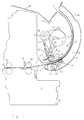
- 1 to 4 show an elevation of one of two on both sides of the sheet edges or forms arranged transport devices during different operating phases.
- Fig. 1 shows the transport device before taking over the cut sheet with open pinch rollers.
- Fig. 2 shows the transport device when closing the pinch rollers for takeover of the sheet.
- FIG 3 shows the transport device at the end of the transport movement for depositing of the sheet.
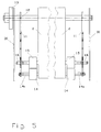
- Fig. 5 shows a schematic representation of the structure of the device according to the invention in frontal view.
- a shaft 3 which from a printer whose transport rollers 4a receives coming sheets 5 loosely.
- the shaft 3 ends with its outlet 7 in a shelf 8.
- the outer wall 1 of the shaft 3 forms together with a rear Cover 9 a further shaft 10 in which a clamping device for detection and is moved to transport the sheets 5.
- the shaft 3 corresponds in terms of its curvature is an arc with a radius equal to the length of the rocker 11 corresponds with the attached clamping device.
- the rocker 11 can by a suitable drive 13 via the bearing shaft 12 also serving as a drive shaft in a Pendulum movement can be pivoted.
- the rocker 11 carries a clamping device for gripping and transporting the sheets 5.
- This clamping device consists of the pinch rollers 14 and 15, which can be closed like scissors.
- the pinch rollers 14.15 grasp the side of the edge of the leaves 5. In one by the position of the rear
- the cutting edge of the blades 5 determines the specific position of the blades 5, the drive 13 the rocker 11 clockwise into the position shown in FIG. 2.
- Through this Movement is guided in a slot of the rocker 11 bearing shaft 16 and Pawl 23, when starting against a rigid bevel associated with the housing G. 17, pressed down against the force of the spring 22.
- With the bearing shaft 16 is also the pinch roller 15 pressed down against the sheet 5.
- the associated extension 18 moves down.
- the wall 1 forms with a cover 9 a shaft in which the pinch roller 14 is moved by the rocker 11.
- This cover 9 is in front of the outlet 7 of the Shaft 3 retracted so far in the manner of a runner 26 that during the pivoting movement the rocker 11 around the axis of the bearing shaft 12, the roller 14 in the area of this Blade 26 forcibly rolls off. This rolling movement causes the sheet 5 to advance is moved from the shaft 3 in the direction of the tray 8.
- the bearing shaft 12 can be designed as a continuous shaft, so that with a drive 13 arranged on both sides of the blade 5 rockers 11 of the device be moved synchronously.
- a variety of driven shafts attached drive rollers the distance of which is determined by the smallest blade length and whose rotary movements must be synchronized, one comes after the invention with a curvature of the only matched to the maximum length of the leaves 5 Shaft and an adapted length of the rocker 11.
- the device according to the invention Since the movement of the cut sheets 5 in the shaft 3 when inserted through the Rollers 4a and / or 4b is completely free, the device according to the invention has none Effects on the movement of the sheets in the printer. This also results in high printing speed and fast sheet sequence very good printing results.
- the Construction allows use with very different throughputs of Leaf as well as use with different leaf lengths and widths.
Landscapes
- Physics & Mathematics (AREA)
- General Physics & Mathematics (AREA)
- Engineering & Computer Science (AREA)
- Mechanical Engineering (AREA)
- Delivering By Means Of Belts And Rollers (AREA)
- Discharge By Other Means (AREA)
Abstract
Description
Claims (8)
- Einrichtung zum Transport einzelner, aus einem Drucker oder dgl. kommenden Blätter oder Formularsätze unter Verwendung eines Schachtes zur Blattführung und mindestens einen in Abhängigkeit der Schnittkante gesteuerten Antrieb durch den die Blätter erfasst und über den Schacht zu einer Ablage od. dgl. bewegt werden, dadurch gekennzeichnet, dass für den Zugriff und den Transport der Blätter (5) beiderseits parallel zu den Rändern des Schachtes (3) geführte, von einem gesteuerten Antrieb (13) pendelartig bewegte Schwingen (11) eingesetzt sind, deren freie Enden mit Klemmvorrichtungen (14,15) zum Erfassen der Blattränder versehen sind.
- Einrichtung nach Anspruch 1, dadurch gekennzeichnet, dass die beiderseits des Schachtes (3) gelagerten Schwingen (11) durch eine Antriebswelle (12) miteinander verbunden sind.
- Einrichtung nach Anspruch 1 und 2, dadurch gekennzeichnet, dass die Schwingen (11) von einem Pendelantrieb (13) mit umkehrbarer Bewegungsrichtung bewegt werden und Elemente vorgesehen sind, durch die bei einer Transportbewegung der Schwinge (11), die Klemmvorrichtung mit den Klemmrollen (14,15) geschlossen und im Bereich des Schachtauslaufes (7) zur Blattablage freigegeben wird.
- Einrichtung nach Anspruch 1 bis 3, dadurch gekennzeichnet, dass die Klemmvorrichtungen bei der Rückbewegung der Schwingen (11) durch das Anlaufen einer Schräge (17) oder dgl. vorzugsweise gegen die Kraft einer Feder (22) geschlossen und verriegelt werden.
- Einrichtung nach Anspruch 1 bis 4, dadurch gekennzeichnet, dass im Bereich des Schachtauslaufes (7) starre Leitkufen (26) derart angeordnet sind, dass die aussen liegenden Klemmrollen (14) durch die Bewegung der Schwinge (11) in Richtung Ablage (8), an der Kufe (26) abrollen und damit das Blatt (5) voreilend aus den Schacht (3) schieben.
- Einrichtung nach Anspruch 1 bis 5, dadurch gekennzeichnet, dass der Antrieb (13) der Schwingen (11) durch eine die hintere Schnittkante des Blattes (5) erfassende Einrichtung oder eine Schneidvorrichtung (6) gesteuert wird.
- Einrichtung nach Anspruch 1 bis 6. dadurch gekennzeichnet, dass zumindest eine der Schwingen (11) seitlich verschiebbar auf der Antriebswelle (12) gehaltert ist.
- Einrichtung nach Anspruch 1 bis 7, dadurch gekennzeichnet. dass eine Mehrzahl Klemmrollen parallel auf die Lagerwellen (14a,16) aufgesetzt sind.
Applications Claiming Priority (2)
| Application Number | Priority Date | Filing Date | Title |
|---|---|---|---|
| DE20118724U DE20118724U1 (de) | 2001-11-16 | 2001-11-16 | Einrichtung zum Transport beschnittener, aus einem Drucker o.dgl. kommender Blätter |
| DE20118724U | 2001-11-16 |
Publications (2)
| Publication Number | Publication Date |
|---|---|
| EP1319618A2 true EP1319618A2 (de) | 2003-06-18 |
| EP1319618A3 EP1319618A3 (de) | 2004-08-25 |
Family
ID=7964101
Family Applications (1)
| Application Number | Title | Priority Date | Filing Date |
|---|---|---|---|
| EP02021321A Withdrawn EP1319618A3 (de) | 2001-11-16 | 2002-09-20 | Einrichtung zum Transport einzelner aus einem Drucker oder dgl. kommenden Blätter |
Country Status (2)
| Country | Link |
|---|---|
| EP (1) | EP1319618A3 (de) |
| DE (1) | DE20118724U1 (de) |
Cited By (1)
| Publication number | Priority date | Publication date | Assignee | Title |
|---|---|---|---|---|
| EP4729451A1 (de) * | 2024-10-15 | 2026-04-22 | KYOCERA Document Solutions Inc. | Bilderzeugungsgerät |
Family Cites Families (5)
| Publication number | Priority date | Publication date | Assignee | Title |
|---|---|---|---|---|
| DE2756904C3 (de) * | 1977-12-16 | 1981-06-11 | Mannesmann AG, 4000 Düsseldorf | Vorrichtung zum Herstellen bedruckter Streifen aus einem Papierband |
| GB2193488B (en) * | 1986-08-05 | 1989-12-20 | Ncr Co | Sheet feeding apparatus |
| GB2210860A (en) * | 1987-10-15 | 1989-06-21 | Tian Sheng Liou | Transferring & stacking printed cards |
| US5362043A (en) * | 1993-08-12 | 1994-11-08 | Tektronix, Inc. | Rotating clamp assembly |
| DE4344493C2 (de) * | 1993-12-24 | 1997-03-20 | Kodak Ag | Innentrommeldrucker mit einem Druckkopf zum Drucken auf ein Papier |
-
2001
- 2001-11-16 DE DE20118724U patent/DE20118724U1/de not_active Expired - Lifetime
-
2002
- 2002-09-20 EP EP02021321A patent/EP1319618A3/de not_active Withdrawn
Cited By (1)
| Publication number | Priority date | Publication date | Assignee | Title |
|---|---|---|---|---|
| EP4729451A1 (de) * | 2024-10-15 | 2026-04-22 | KYOCERA Document Solutions Inc. | Bilderzeugungsgerät |
Also Published As
| Publication number | Publication date |
|---|---|
| DE20118724U1 (de) | 2003-03-27 |
| EP1319618A3 (de) | 2004-08-25 |
Similar Documents
| Publication | Publication Date | Title |
|---|---|---|
| EP0052408B1 (de) | Schreibwerk mit einem Aufzeichnungsorgan und Mitteln zum Umlenken eines Aufzeichnungsträgers | |
| DE1486157B2 (de) | Vorrichtung zum Überführen von bereitgestellten Etiketten auf Gegenstände | |
| EP0017014B1 (de) | Nadeldrucker mit Abschneidevorrichtung | |
| DE68903522T2 (de) | Papierzufuehrvorrichtung fuer einen drucker. | |
| EP0960032B1 (de) | Belegtransport- und anschlageinrichtung | |
| DE2528827C2 (de) | Reißvorrichtung zum Zerteilen eines Endlosformulars in Einzelformulare | |
| DE60026904T2 (de) | Vorrichtung zum Zuführen von flachen Materialien | |
| DE1424635A1 (de) | Einzugsvorrichtung fuer Buchungsmaschinen | |
| DE19855191C2 (de) | Abstapelvorrichtung für eine Ausgabeeinheit einer Druckvorrichtung | |
| EP1319618A2 (de) | Einrichtung zum Transport einzelner aus einem Drucker oder dgl. kommenden Blätter | |
| AT518742B1 (de) | Verfahren zum Bearbeiten von flachen, insbesondere blattförmigen, Werkstücken, Einrichtung und Laserzelle zum Durchführen des Verfahrens | |
| DE1262645B (de) | Rasterdrucker | |
| EP0566697B1 (de) | Transportvorrichtung für abschnitte eines aufzeichnungsträgers aus einem schreibwerk | |
| EP1247775B1 (de) | Falzvorrichtung für Druckbogen | |
| EP0083025A1 (de) | Blattvereinzelungseinrichtung | |
| EP0027859B1 (de) | Ablagehilfe für Papierabschneideeinrichtungen | |
| DE3320613C2 (de) | Verfahren zum Abschneiden einer Aufzeichnungen tragenden Bahn, wie sie in Druckern oder Büromaschinen Verwendung findet und Vorrichtung zur Durchführung des Verfahrens | |
| DE3133028C2 (de) | Vorrichtung zur vereinzelten Entnahme blattförmiger Druckereierzeugnisse, insbesondere Zeitungen | |
| DE948881C (de) | Vorrichtung zum Foerdern eines Papierstreifens in Telegraphenapparaten, insbesondereFernschreibern | |
| DE2420841A1 (de) | Schneidvorrichtung fuer aufzeichnungstraeger o.dgl. | |
| DE734727C (de) | Vorrichtung an Sonderschreib- und Buchungsmaschinen zum Zurueckziehen von Kohlepapier | |
| DE615228C (de) | Papierfuehrungsvorrichtung fuer Schreibmaschinen, Schreibrechenmaschinen o. dgl. | |
| DE2323237C3 (de) | Vorrichtung zum Zuführen von Belegen o.dgl. an die Schreibstelle einer Schreibo.ä. Maschine | |
| DE385565C (de) | Schreibmaschine | |
| DE717602C (de) | Buchheftmaschine |
Legal Events
| Date | Code | Title | Description |
|---|---|---|---|
| PUAI | Public reference made under article 153(3) epc to a published international application that has entered the european phase |
Free format text: ORIGINAL CODE: 0009012 |
|
| AK | Designated contracting states |
Designated state(s): AT BE BG CH CY CZ DE DK EE ES FI FR GB GR IE IT LI LU MC NL PT SE SK TR |
|
| AX | Request for extension of the european patent |
Extension state: AL LT LV MK RO SI |
|
| PUAL | Search report despatched |
Free format text: ORIGINAL CODE: 0009013 |
|
| AK | Designated contracting states |
Kind code of ref document: A3 Designated state(s): AT BE BG CH CY CZ DE DK EE ES FI FR GB GR IE IT LI LU MC NL PT SE SK TR |
|
| AX | Request for extension of the european patent |
Extension state: AL LT LV MK RO SI |
|
| AKX | Designation fees paid | ||
| REG | Reference to a national code |
Ref country code: DE Ref legal event code: 8566 |
|
| STAA | Information on the status of an ep patent application or granted ep patent |
Free format text: STATUS: THE APPLICATION IS DEEMED TO BE WITHDRAWN |
|
| 18D | Application deemed to be withdrawn |
Effective date: 20050401 |