EP1318730B2 - Verbesserung von klemmvorrichtungen für schutzhandschuhe aus metallringgeflecht - Google Patents
Verbesserung von klemmvorrichtungen für schutzhandschuhe aus metallringgeflecht Download PDFInfo
- Publication number
- EP1318730B2 EP1318730B2 EP01972144.8A EP01972144A EP1318730B2 EP 1318730 B2 EP1318730 B2 EP 1318730B2 EP 01972144 A EP01972144 A EP 01972144A EP 1318730 B2 EP1318730 B2 EP 1318730B2
- Authority
- EP
- European Patent Office
- Prior art keywords
- hooking member
- glove according
- anyone
- protection glove
- clinging
- Prior art date
- Legal status (The legal status is an assumption and is not a legal conclusion. Google has not performed a legal analysis and makes no representation as to the accuracy of the status listed.)
- Expired - Lifetime
Links
- 230000001681 protective effect Effects 0.000 title abstract description 7
- 210000000707 wrist Anatomy 0.000 claims abstract description 32
- 210000000245 forearm Anatomy 0.000 claims abstract description 5
- 239000004744 fabric Substances 0.000 claims description 41
- 239000002184 metal Substances 0.000 claims description 18
- 238000004049 embossing Methods 0.000 claims 1
- 229910001220 stainless steel Inorganic materials 0.000 description 4
- 241000287107 Passer Species 0.000 description 3
- 229910000831 Steel Inorganic materials 0.000 description 3
- 230000000295 complement effect Effects 0.000 description 3
- 229940082150 encore Drugs 0.000 description 3
- 239000010935 stainless steel Substances 0.000 description 3
- 239000010959 steel Substances 0.000 description 3
- 210000001519 tissue Anatomy 0.000 description 3
- 238000004140 cleaning Methods 0.000 description 2
- 238000003780 insertion Methods 0.000 description 1
- 230000037431 insertion Effects 0.000 description 1
- 238000002955 isolation Methods 0.000 description 1
- 238000012423 maintenance Methods 0.000 description 1
- 235000013372 meat Nutrition 0.000 description 1
- 210000000056 organ Anatomy 0.000 description 1
- 230000001737 promoting effect Effects 0.000 description 1
- 230000002441 reversible effect Effects 0.000 description 1
Images



Classifications
-
- A—HUMAN NECESSITIES
- A41—WEARING APPAREL
- A41F—GARMENT FASTENINGS; SUSPENDERS
- A41F1/00—Fastening devices specially adapted for garments
- A41F1/06—Glove fasteners
-
- A—HUMAN NECESSITIES
- A41—WEARING APPAREL
- A41D—OUTERWEAR; PROTECTIVE GARMENTS; ACCESSORIES
- A41D19/00—Gloves
- A41D19/015—Protective gloves
- A41D19/01505—Protective gloves resistant to mechanical aggressions, e.g. cutting. piercing
- A41D19/01511—Protective gloves resistant to mechanical aggressions, e.g. cutting. piercing made of wire-mesh, e.g. butchers' gloves
Definitions
- the present invention relates to chainmail gloves used in particular in the meat industry for the protection of the hand and possibly the forearm or the arm of people who use sharp or sharp tools.
- Such gloves are for example described in the documents US-4,471,495 , US-6,076,190 , FR-2,753,883 or FR-2 748 908 .
- These gloves consist of a mesh of intertwined metal rings and they generally have a tightening system at the wrist to ensure their holding on the hand.
- Some models are equipped with an extension that forms a cuff that covers part of the user's arm, or the entire arm. When this cuff is made of chain mail, longitudinal stiffening members ensure its maintenance in tension, and a clamping system can be arranged at its end.
- the wrist area of the chainmail fabric, or the mesh coat cuff forms a complete sleeve without a side slit.
- clamping systems there are many types of clamping systems to ensure the holding of the glove on the hand. Some of these clamping systems have a complex structure or are not simple to use. Others, relatively simple structure, do not retain their tightening characteristics over time; this is particularly the case of metal clamping systems with elastic structure (spiral spring or coil spring) which can relax over time. Still some of these clamping systems pose problems of cleaning, either because of their complex structure, or because they use clamping straps and / or plastic stiffening members that are poorly resistant to laundry or high temperatures.
- the present invention aims to remedy these disadvantages.
- the chainmail glove according to the present invention is of the type consisting of a first part intended to cover the hand, extended by a second part in the form of a complete sleeve devoid of lateral slit, intended to cover the wrist area, which second portion is optionally extended by a protective sleeve of the forearm or the arm, also in the form of a complete sleeve devoid of lateral slit; it is also equipped with a clamping system on the lap portion of the wrist and / or on the protective sleeve.
- This glove is characterized in that its clamping system consists of a hooking member adapted to cooperate with one of a plurality of orifices arranged in a hooking structure attached to a part of the periphery of the zone of the wrist or cuff of the mesh coat fabric, which hooking member is provided with a flat end hook whose length l is greater than the internal diameter of the rings of the coat of mail fabric, and a protruding element which constitutes a gripping means facilitating the engaging maneuvers on said attachment structure, as well as the stall maneuvers.
- This clamping device structure is very simple to achieve; it is also very efficient and safe to use.
- this hooking member is advantageously made by cutting and stamping / folding a sheet of metal.
- the hooking member is in the form of a flat structure provided with a flat end hook which constitutes the hook cooperating with the or one of the orifices of the hooking structure.
- protruding member of said hooking member in the form of a transverse edge formed from the top face of said planar structure.
- This projecting element preferably extends in a plane inclined relative to the plane perpendicular to the top face of the flat structure, to facilitate handling hooking and unhooking.
- the hooking member is in the form of a flat structure provided with a flat end hook which constitutes the hook cooperating with the or one of the orifices of the structure of the structure. hooking, the projecting element of said hooking member being in the form of a boss arranged from the top face of said planar structure, provided with a face or a transverse edge promoting grip .
- the flat end hook which constitutes the hook of the hooking member comprises slightly beveled, converging side edges, which give it a generally trapezoidal shape favoring the insertion and the disembedding in the orifices of the hanging structure.
- the hooking structure is in the form of ring (s) reported (s), taken in the fabric mail coat.
- This or these rings may have a general rectangular, oval, circular or other shape.
- the attachment structure is in the form of a plate provided with a plurality of orifices, to allow adjustment of the clamping tension.
- This plate is advantageously curved to follow the contour of the wrist or the arm of the user.
- the attachment structure is in the form of several plates juxtaposed or partially overlapping, each having at least one orifice, to allow adjustment of the clamping tension.
- the holes of the attachment structure are elongated and arranged parallel to each other; in addition, the hooking member comprises an end hook which is active over the entire length or substantially the entire length of said orifices.
- the fastening structure is fixed on the chainmail fabric, and the rear end of the hooking member is also fixed on the chainmail fabric, at a distance from said attachment structure to allow clamping on the corresponding glove area.
- the rear end of the hooking member is attached to the chainmail fabric via one or more plates associated with each other.
- the clamping system consists of a monobloc strip coming to surround the corresponding glove area; one of the ends of this strip is shaped to form the hooking member, and its other end is shaped to form the attachment structure.
- This strip can be maintained on the corresponding glove area by means of one or more passers chain mail, or through a sleeve chain mail.
- the clamping system consists of a hooking member and a hooking structure attached to the ends of an attached strap, which strap is in the form of a strip or of a platelet association.
- a system of passer (s) or sleeve mesh to hold the strap on the corresponding glove area.
- a complementary plate can be fixed at the end of the attachment structure by an articulated connection; this additional plate is housed in the sleeve which accommodates the strap-shaped strip or association of pads.
- the receiving sleeve of the strap or strip extends from each of the ends of the attachment structure, and it comprises an exit slot for the end of said strap or said strap. strap provided with the hooking member.
- the glove 1 shown on Figures 1 and 2 is made of chain mail fabric, that is to say that it consists of a mesh of interlaced metal rings.
- the corresponding rings may be made of 0.5 or 0.55 mm diameter stainless steel wire; their internal diameter may be of the order of 2 to 4 mm.
- This glove 1 comprises a part "hand" 2 extended by a portion 3 in the form of a complete cylindrical sleeve, that is to say without a side slot, which is intended to come to cover the wrist of the user.
- This part 3 is extended itself by an extension 4, shown partially, forming a protective sleeve of the forearm or the arm; this protective sleeve 4 is also in the form of a complete cylindrical sleeve, devoid of lateral slit.
- the three parts of glove 2, 3 and 4 are made of monobloc fabric mail coat.
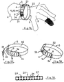
- the cylindrical portion 3 of the wrist area is equipped with a clamping system 5 consisting of a hooking member 6 provided with an end hook 7 which cooperates with one of the orifices 8 of a structure of FIG. reported hooking 9, here platinum-shaped.
- the hooking member 6 is detailed on the Figures 3 and 4 . It is in the general form of a flat plate-shaped structure 10 whose front end has a slightly "return" plane return constituting the hook 7, and whose rear end is equipped with orifices 11, here at number of two, intended for fixing on the fabric of chain mail.
- a transverse edge 12 protrudes from the top face of the flat structure 10 to facilitate hooking and unhooking maneuvers. This transverse edge 12 extends in a plane slightly inclined relative to the plane perpendicular to the top face of the planar structure 10 to optimize handling.
- the hook 7 and the transverse edge 12 are each arranged on one side of the flat structure 10 of the hooking member 6, and they are both slightly inclined in the same direction, this direction being opposite to the direction of traction required to close the clamping device.
- the hooking member 6 illustrated on the Figures 1 to 4 is made by cutting and folding a metal sheet, for example a 0.7 mm thick stainless steel sheet; its width may be of the order of 1.5 to 2.5 cm, and the hook 7 may extend over a length l corresponding to about half or two thirds of this width.
- the hook 7 is centered on the width of the hooking member 6.
- the transverse edge 12 extends over the entire width of the hook member 6; it is obtained by a folding Vee of the metal sheet.
- the lateral edges 13 of the hook 7 are slightly bevelled or biased to facilitate the maneuvers hooking and especially stall on the or holes 8 of the attachment structure 9. These two convergent edges 13 give the hook 7 a general shape trapezoidal.
- the corresponding beveling is of the order of a few degrees.
- the depth of the hook 7 is adapted to optimize the attachment to the or holes 8 of the attachment structure 9; this depth can be of the order of 4 to 5 mm.
- the general dimensions of the hook 7 are adapted to prevent any direct attachment to the rings of the mail coat fabric.
- the length 1 of the hook 7 is greater than the internal diameter of the rings used to make the coat of mail mesh structure of the glove.
- the attachment structure 9 is detailed on the figure 5 .
- This hooking structure 9, of generally rectangular shape, can also be cut in a metal sheet (for example a 0.7 mm thick stainless steel sheet). It may have a width of the order of 1.5 to 2.5 cm, and its length may be of the order of a few centimeters.
- This attachment structure 9 is slightly curved to fit the best contour of the wrist of the user.
- the orifices 8 intended to cooperate with the hook 7 of the hooking member 6 are regularly distributed parallel to each other along the length of the attachment structure 9; these orifices 8 have an elongated shape whose length corresponds, with play, to the length l of the upper part of the hook 7; their width is slightly greater than the thickness of said hook 7.
- the number and positioning of the elongated holes 8 are a function of the clamping possibilities that it is desired to obtain.
- the attachment structure 9 is fixed on the chain mail fabric of the wrist area 3 via metal rings 15 (for example rings identical or similar to those used for making the glove).
- the rings 15 are caught on certain rings of the chain mail fabric, and they pass through the aforementioned orifices 14 of the fastening structure 9.
- the hooking structure 9 is thus substantially plated on the chain mail fabric, on a part of the periphery of the wrist. Note that the presence of orifices 8 and 14 improves the flexibility of the attachment structure 9 which can thus marry the contour of the wrist.
- the hooking member 6 is also fixed on the wrist area 3, at some distance from the attachment structure 9, by means of metal fixing rings 16. Again, these rings 16 may be identical or similar to those used for making the glove.
- the rings 16 are hooked on some rings of the chainmail fabric, and they pass through the end holes 11 of the hooking member 6. This hooking member is then somehow "articulated" on the fabric coat of meshes of the glove, its front end provided with the hook 7 being free.
- the hooking member may be fixed to the coat of mail fabric of the glove by means of a metal plate, or several plates hinged to each other.
- the tightening of the wrist area is carried out very simply as illustrated on the figure 1 by a traction maneuver on the hooking member 6 to insert its hook 7 into one of the orifices 8 of the hooking structure 9. This maneuver is facilitated by the presence of the protruding ridge 12 .
- the choice of the orifice 8 used is a function of the desired tightening characteristics.
- the "activated" clamping device is shown on the figure 2 .
- the corresponding clamping achieved by means of a hooking member which is releasably lock on a hole specially arranged in a hooking structure, is very easy to achieve. This tightening is also of excellent quality.
- the slight inclination of the hook 7 makes it possible to optimize the hooking on the hooking structure 9.
- the use of an active flat hook 7 over the entire length or substantially the entire length of the elongated orifice 8 reception improves the fastening of the hook member on the attachment structure.
- the attachment structure 9 ' consists of a plurality of independent inserts 17 partially superimposed and fixed on the chain mail fabric by means of connecting rings 18.
- Each plate 17 has an orifice 8 allowing the embedding of the hook 7 of the hooking member 6.
- each plate could comprise two orifices 8 parallel or more.
- the plates 17 are also fixed on the fabric chain mail through junction rings 18, but the plates 17 are here simply juxtaposed (they do not overlap). Again, each plate 17 could have more than one orifice 8.
- FIG. 8 and 9 illustrate yet another possible variant of attachment structure.
- This hooking structure 9 "consists of at least one independent ring 19" caught "in the mail coat fabric as illustrated in FIG. figure 8 .
- the ring or rings 19 are advantageously made of wire; they are advantageously “taken” in the fabric of chain mail before closing by a weld spot. They overflow over the fabric of chainmail to allow the gripping of the hook 7 of the hooking member 6. They can advantageously overflow on both sides of the chain mail fabric to obtain the an ambidextrous reversible glove.
- the hooking member, and in particular its attachment to the glove must then be adapted accordingly.
- the hooking rings 19 may have a rectangular contour. They can also be in other forms, for example oval ( figure 10 ) or circular ( figure 11 ).
- FIG. 12 and 13 illustrate a possible variant of the hooking member.
- This hooking member 6 ' consists of a flat plate-shaped structure 10' whose front end is provided with the hook 7 'and whose rear end has fixing orifices 11'.
- a projecting element 12 ' is arranged from the top face of the planar structure 10' to form the gripping means facilitating the attachment maneuvers on the attachment structure, as well as the stall maneuvers.
- This protruding element 12 ' is in the form of a boss made by stamping after transverse cutting. This boss defines a transverse edge to the rear which facilitates the manipulation at the medium of one or more fingers.
- FIGS 14 and 15 illustrate another possible embodiment of the clamping device 5 according to the present invention.
- the hooking member 6 and the hooking structure 9 have a structure identical or similar to that just described in connection with the Figures 1 to 5 but these two elements are shaped at the ends of a strip 20 which forms a kind of strap and which surrounds the wrist area.
- the strip 20 may consist of a metal strip, for example a steel strip 1.5 cm wide and 0.2 mm thick, the ends of which are folded and cut in a suitable manner.
- FIGS. Figures 14 and 15 The one-piece clamping device illustrated in FIGS. Figures 14 and 15 .
- This clamping device has a generally circular shape; as illustrated on the figure 14 it can be housed in a sleeve 21 arranged on the glove 1, on a part of the periphery of the wrist area.
- the receiving sleeve 21 is advantageously made of chain mail, for example by means of an attached band and fixed on the wrist area by means of metal seam rings. It is preferably arranged on the entire periphery of the wrist, except on the attachment structure 9, to allow clamping.
- the sleeve 21 may be replaced by simple passers chain mail.
- the hooking structure 9 is fastened to the chainmail fabric of the glove by means of metal rings 15 which pass through the circular orifices 14, in a manner similar to the previous embodiment.
- FIGS. Figures 1 to 5 illustrate another embodiment in which the clamping device 5 consists of a hooking member 6 and a hooking structure 9 as illustrated in FIGS. Figures 1 to 5 , connected at one of their ends by an attached strip 22 which forms a kind of strap.
- the rear end of the hooking member 6 is attached to one end of the strip 22 by connecting rings 23; and the rear end of the hooking structure 9 is attached to the other end of the strip 22 by connecting rings 24.
- the hooking member 6 and the hooking structure 9 can be made in a stainless steel sheet of 0.7 mm thick to give them a suitable strength, while the strip 22 can be made from a 0.2 mm thick steel sheet to give it good flexibility.
- FIG. Figures 14 and 15 A circular clamping device similar to that illustrated in FIG. Figures 14 and 15 . On the figure 17 this clamping device is shown isolated and in a loose position; on the figure 18 it is represented in the activated position.
- the strip 22 can be housed in a sleeve of mesh 21 arranged on the wrist area of the glove, this sleeve 21 extending substantially from the ends of the attachment structure 9.
- this structure of 9 is preferably fastened to the chain mail fabric by means of metal rings 15 which pass through the circular orifices 14.
- the sleeve 21 can be replaced by chain mail loops.
- the manipulation of the hooking member 6 is very easy because of its attachment to the strip 22 through the connecting rings 23 which provide an articulated connection.
- the sleeve 21 stops at some distance from the hooking structure 9 to facilitate clamping and loosening manipulations.
- the strip 22 may be replaced by a strap 25 consisting of an assembly of metal plates 26 by means of connecting rings 27, as illustrated in FIG. figure 19 .
- FIGS. 20 to 24 show an embodiment derived from that illustrated on the Figures 16 to 19 .
- the end of the attachment structure 9 which is not connected to the strip 22 is extended by a complementary plate 28 connected by connecting rings 29.
- This additional plate 28 may be made in a steel sheet 0.2 mm thick; its width corresponds substantially to that of the strip 22 and extends over a length of a few centimeters.
- the clamping device obtained is illustrated in isolation on the figure 21 in the loosened position, and in the active position on the figure 22 .
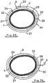
- the complementary plate 28 is intended to be housed in the sleeve 21 arranged on the periphery of the wrist area. Its presence makes it possible to distribute the mesh fabric around the wrist circumference during the tightening operation.
- the sleeve 21 starts closest to the end of the attachment structure 9 to optimize this distribution of the chain mail; to have a good margin of maneuver during the manipulation of the hooking member, the end of the strip 22 which carries said hooking member out of the sleeve 21 by a slot 30 arranged a few centimeters from the end of said sleeve .
- the corresponding structure of the clamping device 5 is illustrated on the Figures 23 and 24 .
- the figure 23 shows this clamping device in the active position, the hooking member 6 being secured to the attachment structure 9; the figure 24 shows it in the off position.
- the strip 22 may also be replaced by an assembly of metal plates.
- the clamping device according to this The invention may likewise be arranged at the end of the cuff 4 or at an intermediate zone of this cuff.
- the hooking member 6 can be replaced by other embodiments, in particular by the solution illustrated on the Figures 12 and 13 .
Landscapes
- Engineering & Computer Science (AREA)
- Textile Engineering (AREA)
- Gloves (AREA)
- Professional, Industrial, Or Sporting Protective Garments (AREA)
Claims (20)
- Schutzhandschuh aus Metallringgeflecht, d.h. der aus einem Geflecht von ineinander verschlungenen metallischen Ringen gebildet ist, wobei der Handschuh aus einem Teil (2), der dazu bestimmt ist, die Hand zu bedecken, gebildet ist, welcher durch einen Teil (3) in Form einer kompletten Hülle ohne seitlichen Schlitz verlängert ist, der dazu bestimmt ist, die Handgelenkszone zu bedecken, wobei der Handgelenksteil (3) eventuell durch eine Schutzmanschette (4) für den Unterarm oder Arm verlängert ist, die ebenfalls die Form einer kompletten Hülle ohne seitlichen Schlitz hat, wobei der Handschuh mit einem Klemmsystem (5) auf dem Teil (3) zur Handgelenksabdeckung und/oder auf der Schutzmanschette (4) versehen ist, dadurch gekennzeichnet, dass das Klemmsystem (5) von einem Hakenelement (6, 6') gebildet ist, das geeignet ist, mit einer von einer Mehrzahl von Öffnungen (8) zusammenzuwirken, die in einer an einem Teil des Umfangs der Handgelenks- oder der Manschettenzone des Metallringgeflechts angebrachten Befestigungsstruktur (9, 9', 9") vorgesehen sind, wobei das Hakenelement (6, 6') mit - einem flachen Endhaken (7, 7'), dessen Länge I größer als der Innendurchmesser der Ringe des Metallringgeflechts ist, und - einem vorspringenden Element (12, 12') versehen ist, das ein Greifmittel bildet, das die Handgriffe zur Befestigung auf der Befestigungsstruktur (9, 9', 9") sowie die Handgriffe des Loshakens erleichtert.
- Schutzhandschuh nach Anspruch 1, dadurch gekennzeichnet, dass das Hakenelement (6, 6') durch Ausschneiden und Ziehen/Falzen einer Metallfolie hergestellt ist.
- Schutzhandschuh nach einem der Ansprüche 1 oder 2, dadurch gekennzeichnet, dass das Hakenelement (6) die Form einer flachen Struktur (10) hat, die mit einem flachen Endhaken (7) versehen ist, der den Haken darstellt, der mit einer der Öffnungen (8) der Befestigungsstruktur (9, 9', 9") zusammenwirkt, wobei das vorspringende Element (12) in Form einer Querkante vorhanden ist, die von der Oberseite der flachen Struktur (10) ausgehend vorgesehen ist.
- Schutzhandschuh nach Anspruch 3, dadurch gekennzeichnet, dass sich das vorspringende Element (12) des Hakenelements (6) in einer in Bezug auf die zur Oberseite der flachen Struktur (10) senkrechten Ebene geneigten Ebene erstreckt, um die Handgriffe des Einhakens und Loshakens zu erleichtern.
- Schutzhandschuh nach einem der Ansprüche 1 oder 2, dadurch gekennzeichnet, dass das Hakenelement (6') die Form einer flachen Struktur (10') hat, die mit einem flachen Endhaken (7') versehen ist, der den Haken darstellt, der mit der oder einer der Öffnungen (8) der Befestigungsstruktur (9, 9', 9") zusammenwirkt, wobei das vorspringende Element (12') die Form eines Buckels hat, der von der Oberseite der flachen Struktur (10) ausgehend vorgesehen ist, wobei der Buckel mit einer Querseite oder -kante versehen ist, die das Angreifen begünstigt.
- Schutzhandschuh nach einem der Ansprüche 1, 3, 4 oder 5, dadurch gekennzeichnet, dass der flache Endhaken (7, 7'), der den Haken des Hakenelements (6, 6') darstellt, Seitenränder (13, 13'), die leicht abgeschrägt und zusammenlaufend sind, aufweist, die ihm eine allgemeine Trapezform verleihen.
- Schutzhandschuh nach einem der Ansprüche 1 bis 6, dadurch gekennzeichnet, dass die Befestigungsstruktur (9") die Form von aufgesetzten Ring(en) (19) hat, die mit dem Metallgeflecht "in Eingriff stehen".
- Schutzhandschuh nach einem der Ansprüche 1 bis 6, dadurch gekennzeichnet, dass die Befestigungsstruktur (9) die Form einer Platte hat, die mit einer Vielzahl von Öffnungen (8) versehen ist, um eine Einstellung der Klemmspannung zu ermöglichen.
- Schutzhandschuh nach Anspruch 8, dadurch gekennzeichnet, dass die Befestigungsstruktur (9) gebogen ist, um der Kontur des Handgelenks oder des Arms des Benutzers zu folgen.
- Schutzhandschuh nach einem der Ansprüche 1 bis 6, dadurch gekennzeichnet, dass die Befestigungsstruktur (9') die Form von mehreren nebeneinander liegenden oder einander teilweise überlappenden Platten (17) aufweist, die jeweils mindestens eine Öffnung (8) umfassen, um eine Einstellung der Klemmspannung zu ermöglichen.
- Schutzhandschuh nach einem der Ansprüche 8 bis 10, dadurch gekennzeichnet, dass die Öffnungen (8) länglich und parallel zueinander angeordnet sind und dass das Hakenelement (6, 6') einen Endhaken (7, 7') umfasst, der auf der gesamten Länge oder im Wesentlichen der gesamten Länge der Öffnungen (8) aktiv ist.
- Schutzhandschuh nach einem der Ansprüche 1 bis 11, dadurch gekennzeichnet, dass die Befestigungsstruktur (9, 9', 9") auf dem Metallringgeflecht befestigt ist und dass das hintere Ende des Hakenelements (6, 6') ebenfalls auf dem Metallringgeflecht in einigem Abstand zu der Struktur (9, 9', 9") befestigt ist, um ein Festklemmen auf der entsprechenden Handschuhzone zu ermöglichten.
- Schutzhandschuh nach einem der Ansprüche 1 bis 11, dadurch gekennzeichnet, dass die Befestigungsstruktur (9, 9', 9") auf dem Metallringgeflecht befestigt ist und dass das hintere Ende des Hakenelements (6, 6') auf dem Metallringgeflecht mit Hilfe eines Plättchens oder mehrerer miteinander verbundener Plättchen befestigt ist.
- Schutzhandschuh nach einem der Ansprüche 1 bis 11, dadurch gekennzeichnet, dass das Klemmsystem (5) von einem einstückigen Band (20) gebildet ist, das die entsprechende Handschuhzone umgibt und bei dem eines der Enden derart ausgebildet ist, dass das Hakenelement (6, 6') gebildet wird, und dessen anderes Ende derart ausgeführt ist, dass die Befestigungsstruktur (9) gebildet wird.
- Schutzhandschuh nach einem der Ansprüche 1 bis 11, dadurch gekennzeichnet, dass das Hakenelement (6, 6') und die Befestigungsstruktur (9) an den Enden eines aufgesetzten Gurtes in Form eines Bandes (22) oder einer Verbindung von Plättchen (26) befestigt sind.
- Schutzhandschuh nach einem der Ansprüche 14 oder 15, dadurch gekennzeichnet, dass er mindestens einen Durchgang zum Halten des Gurts (22,25) oder des Bandes (20) auf der entsprechenden Handschuhzone umfasst.
- Schutzhandschuh nach einem der Ansprüche 14 oder 15, dadurch gekennzeichnet, dass er eine Hülle (21) aus Metallgeflecht umfasst, in der mindestens ein Teil des Gurts (22,25) oder des Bandes (20) zu liegen kommt.
- Schutzhandschuh nach Anspruch 17; dadurch gekennzeichnet, dass das Klemmsystem (5) mit einer komplementären Platte (28) versehen ist, die im Bereich des Endes der Befestigungsstruktur (9) durch eine Gelenkverbindung befestigt ist, wobei die komplementäre Platte (28) in der Aufnahmehülle (21) des Gurts (22,25) oder des Bandes (20) zu liegen kommt.
- Schutzhandschuh nach Anspruch 18; dadurch gekennzeichnet, dass sich die Aufnahmehülle (21) des Gurts (22, 25) oder des Bandes (20) von jedem der Enden der Befestigungsstruktur (9) ausgehend erstreckt, wobei die Hülle (21) einen Austrittsschlitz (30) für das Ende des Gurts oder des Bandes, das mit dem Hakenelement (6, 6') versehen ist, umfasst,
- Schutzhandschuh nach einem der Ansprüche 14 bis 19, dadurch gekennzeichnet, dass die Befestigungsstruktur (9) in Form einer auf dem Metallgeflecht mit Hilfe von Verbindungsringen (15) befestigten Platte ausgeführt ist.
Applications Claiming Priority (3)
| Application Number | Priority Date | Filing Date | Title |
|---|---|---|---|
| FR0011749A FR2813763B1 (fr) | 2000-09-12 | 2000-09-12 | Perfectionnement aux dispositifs de serrage pour gants de protection en cotte de mailles |
| FR0011749 | 2000-09-12 | ||
| PCT/FR2001/002823 WO2002021952A1 (fr) | 2000-09-12 | 2001-09-11 | Perfectionnement aux dispositifs de serrage pour gants de protection en cotte de mailles |
Publications (4)
| Publication Number | Publication Date |
|---|---|
| EP1318730A1 EP1318730A1 (de) | 2003-06-18 |
| EP1318730B1 EP1318730B1 (de) | 2005-11-09 |
| EP1318730B2 true EP1318730B2 (de) | 2018-02-07 |
| EP1318730B9 EP1318730B9 (de) | 2018-05-23 |
Family
ID=8854317
Family Applications (1)
| Application Number | Title | Priority Date | Filing Date |
|---|---|---|---|
| EP01972144.8A Expired - Lifetime EP1318730B9 (de) | 2000-09-12 | 2001-09-11 | Verbesserung von klemmvorrichtungen für schutzhandschuhe aus metallringgeflecht |
Country Status (12)
| Country | Link |
|---|---|
| US (1) | US7188373B2 (de) |
| EP (1) | EP1318730B9 (de) |
| AT (1) | ATE308901T1 (de) |
| AU (1) | AU2001291937A1 (de) |
| BR (1) | BR0113828A (de) |
| DE (1) | DE60114861D1 (de) |
| ES (1) | ES2250479T3 (de) |
| FR (1) | FR2813763B1 (de) |
| HU (1) | HU228214B1 (de) |
| MX (1) | MXPA03002098A (de) |
| SK (1) | SK4072003A3 (de) |
| WO (1) | WO2002021952A1 (de) |
Families Citing this family (18)
| Publication number | Priority date | Publication date | Assignee | Title |
|---|---|---|---|---|
| DE10116922C1 (de) * | 2001-04-05 | 2002-07-04 | Muench Friedrich Gmbh & Co Kg | Schutzbekleidung, insbesondere aus Metallringgeflecht |
| FR2825589B1 (fr) * | 2001-06-06 | 2004-07-02 | Manulatex France | Gant de protection ambidextre |
| US8020279B2 (en) | 2003-03-12 | 2011-09-20 | Kaynemaile Limited | Methods and apparatus for forming mesh and link elements |
| US8043546B2 (en) | 2003-03-12 | 2011-10-25 | Kaynemaile Limited | Mesh and methods and apparatus for forming and using mesh |
| DE10358432B4 (de) * | 2003-12-13 | 2005-12-01 | Ziegler Mechanische Werkstatt, Metallgewebe Und Arbeitsschutz Gmbh | Federspanner |
| DE202005011181U1 (de) * | 2005-07-11 | 2005-10-06 | Friedrich Münch GmbH + Co. KG | Schutzhandschuh aus einem Metallringgeflecht |
| FR2899441B1 (fr) * | 2006-04-10 | 2008-07-04 | Manulatex France Soc Par Actio | Article en cotte de mailles equipe d'un organe elastique de resserrement ou de mise en tension |
| FR2899440B1 (fr) * | 2006-04-10 | 2008-07-04 | Manulatex France Soc Par Actio | Gant de protection en cotte de mailles muni de moyens de mise en tension de la maille |
| US7703151B2 (en) * | 2006-08-28 | 2010-04-27 | Blauer Manufacturing Company, Inc. | Cuff closure for reversible garments |
| WO2011046900A1 (en) * | 2009-10-14 | 2011-04-21 | Us Mesh, Inc. | Protective glove |
| DK2327319T3 (da) * | 2009-11-26 | 2013-01-02 | Ziegler Arbeitsschutz Gmbh | Beklædningsstykke omfattende i det mindste delvis et metalringfletværk |
| DE202012103421U1 (de) * | 2012-09-07 | 2013-01-14 | Friedrich Münch GmbH & Co. KG | Schließband zur Befestigung an einer aus einem Metallringgeflecht gebildeten Schlaufe einer Schutzbekleidung und solch eine Schutzbekleidung |
| USD737525S1 (en) | 2013-11-21 | 2015-08-25 | Us Mesh, Inc. | Cut resistant glove with elastomeric strap |
| US20150164158A1 (en) * | 2013-12-13 | 2015-06-18 | Honeywell International Inc. | Protective overglove for glove-box gloves |
| USD741551S1 (en) | 2014-02-14 | 2015-10-20 | Us Mesh, Inc. | Cut resistant glove with elastomeric strap |
| USD802221S1 (en) | 2014-11-20 | 2017-11-07 | Us Mesh Llc | Cut resistant glove with elastomeric straps |
| KR102317271B1 (ko) * | 2019-10-29 | 2021-10-22 | 이종영 | 손가락 베임 방지용 보호구 |
| US11980243B2 (en) * | 2022-07-08 | 2024-05-14 | Brad Hackathorn | Microchip security protection glove device |
Citations (3)
| Publication number | Priority date | Publication date | Assignee | Title |
|---|---|---|---|---|
| US5054126A (en) † | 1990-09-21 | 1991-10-08 | Saf-T-Gard International, Inc. | Reversible protective glove |
| EP0758854B1 (de) † | 1994-05-09 | 1998-09-02 | Friedrich Münch GmbH & Co. KG | Schutzhandschuh |
| US5894602A (en) † | 1998-06-03 | 1999-04-20 | Wdc Holdings, Inc. | Protective glove |
Family Cites Families (11)
| Publication number | Priority date | Publication date | Assignee | Title |
|---|---|---|---|---|
| DE80331C (de) * | ||||
| US4471495A (en) * | 1983-01-14 | 1984-09-18 | Whiting And Davis Company, Inc. | Protective glove |
| US5088123A (en) * | 1991-05-10 | 1992-02-18 | Whiting And Davis Company, Inc. | Protective garment |
| NL9401704A (nl) * | 1994-10-14 | 1996-05-01 | Johannes Adrianus Augustinus V | Veiligheidshandschoen uit metalen ringen, voorzien van elastische sluitingen en gesloten pols- en arm-gedeelten. |
| US5511241A (en) * | 1994-11-14 | 1996-04-30 | Azon Corporation | Chain mail garments impregnated with an elastomeric material |
| FR2748908B1 (fr) * | 1996-05-24 | 1998-08-14 | Manulatex | Gant de protection en cotte de maille |
| FR2753883B1 (fr) * | 1996-09-27 | 1998-12-18 | Manulatex France | Perfectionnement aux gants de protection en cotte de mailles |
| FR2775165B1 (fr) * | 1998-02-26 | 2000-04-28 | Foin Ets | Gant de protection en tissu de cotte de maille |
| FR2776482B1 (fr) * | 1998-03-27 | 2000-06-16 | Manulatex France | Perfectionnement aux gants en cotte de mailles |
| FR2802062B1 (fr) * | 1999-12-08 | 2002-08-02 | Manulatex France | Dispositif de serrage pour article vestimentaire en cotte de mailles |
| US6457182B1 (en) * | 2001-06-08 | 2002-10-01 | The United States Of America As Represented By The Secretary Of The Army | Protective glove |
-
2000
- 2000-09-12 FR FR0011749A patent/FR2813763B1/fr not_active Expired - Fee Related
-
2001
- 2001-09-11 EP EP01972144.8A patent/EP1318730B9/de not_active Expired - Lifetime
- 2001-09-11 US US10/380,067 patent/US7188373B2/en not_active Expired - Fee Related
- 2001-09-11 WO PCT/FR2001/002823 patent/WO2002021952A1/fr not_active Ceased
- 2001-09-11 MX MXPA03002098A patent/MXPA03002098A/es not_active Application Discontinuation
- 2001-09-11 HU HU0301041A patent/HU228214B1/hu not_active IP Right Cessation
- 2001-09-11 ES ES01972144T patent/ES2250479T3/es not_active Expired - Lifetime
- 2001-09-11 AT AT01972144T patent/ATE308901T1/de not_active IP Right Cessation
- 2001-09-11 BR BR0113828-6A patent/BR0113828A/pt not_active Application Discontinuation
- 2001-09-11 DE DE60114861T patent/DE60114861D1/de not_active Expired - Lifetime
- 2001-09-11 SK SK407-2003A patent/SK4072003A3/sk unknown
- 2001-09-11 AU AU2001291937A patent/AU2001291937A1/en not_active Abandoned
Patent Citations (3)
| Publication number | Priority date | Publication date | Assignee | Title |
|---|---|---|---|---|
| US5054126A (en) † | 1990-09-21 | 1991-10-08 | Saf-T-Gard International, Inc. | Reversible protective glove |
| EP0758854B1 (de) † | 1994-05-09 | 1998-09-02 | Friedrich Münch GmbH & Co. KG | Schutzhandschuh |
| US5894602A (en) † | 1998-06-03 | 1999-04-20 | Wdc Holdings, Inc. | Protective glove |
Also Published As
| Publication number | Publication date |
|---|---|
| FR2813763A1 (fr) | 2002-03-15 |
| US7188373B2 (en) | 2007-03-13 |
| EP1318730B9 (de) | 2018-05-23 |
| AU2001291937A1 (en) | 2002-03-26 |
| MXPA03002098A (es) | 2004-09-10 |
| ES2250479T3 (es) | 2006-04-16 |
| US20040025223A1 (en) | 2004-02-12 |
| DE60114861D1 (de) | 2005-12-15 |
| SK4072003A3 (en) | 2004-01-08 |
| ATE308901T1 (de) | 2005-11-15 |
| HUP0301041A3 (en) | 2008-08-28 |
| BR0113828A (pt) | 2004-02-10 |
| HU228214B1 (en) | 2013-02-28 |
| EP1318730B1 (de) | 2005-11-09 |
| EP1318730A1 (de) | 2003-06-18 |
| WO2002021952A1 (fr) | 2002-03-21 |
| FR2813763B1 (fr) | 2003-01-24 |
| HUP0301041A2 (hu) | 2003-09-29 |
Similar Documents
| Publication | Publication Date | Title |
|---|---|---|
| EP1318730B9 (de) | Verbesserung von klemmvorrichtungen für schutzhandschuhe aus metallringgeflecht | |
| EP2549860B1 (de) | Angelköder | |
| EP1065951B1 (de) | Schutzhandschuh aus einem metallringgeflecht | |
| JP3121285B2 (ja) | 髪止め具 | |
| CA2414551A1 (fr) | Pince multifonctions a usage medical comportant deux machoires articulees | |
| WO2002098249A1 (fr) | Gant de protection ambidextre. | |
| CA2650673A1 (fr) | Pince a verrouillage | |
| CA2896409A1 (fr) | Masque de protection des yeux, notamment pour la pratique du ski | |
| EP2134162B1 (de) | Fessel für einen identifikationsring | |
| FR2748908A1 (fr) | Gant de protection en cotte de maille | |
| EP0540701A1 (de) | Ködervorrichtung für einen Reissverschluss. | |
| EP2552270B1 (de) | Vorrichtung zum verschliessen und befestigen zweier längen einer biegsamen umreifung | |
| FR2587172A1 (fr) | Tete plombee pour ligne a peche | |
| EP1611786B1 (de) | Angelzubehör, insbesondere Drahtschneider | |
| FR2753883A1 (fr) | Perfectionnement aux gants de protection en cotte de mailles | |
| EP0608580A1 (de) | Schnalle | |
| FR2802062A1 (fr) | Dispositif de serrage pour article vestimentaire en cotte de mailles | |
| EP1875823A1 (de) | Schnallen mit zwei trennbaren Teilen zur Befestigung eines V-Gurts und ihre Benutzung zur Befestigung eines Schutzhelms | |
| EP3913253A1 (de) | Haken für elastischen spanner und spanner mit diesem haken | |
| WO2002022435A1 (fr) | Pret-a-monter de fixation d'un porte-bidon | |
| FR3157098A1 (fr) | Système de fixation | |
| CA2424939A1 (fr) | Dispositif de fixation et/ou d'assemblage | |
| EP2335880A2 (de) | Seitenschneider für Kabelbinder | |
| FR2802061A1 (fr) | Gant en cotte de mailles | |
| FR2470063A1 (fr) | Element d'extremite tel qu'un couvercle pour receptacle en grillage |
Legal Events
| Date | Code | Title | Description |
|---|---|---|---|
| PUAI | Public reference made under article 153(3) epc to a published international application that has entered the european phase |
Free format text: ORIGINAL CODE: 0009012 |
|
| 17P | Request for examination filed |
Effective date: 20030414 |
|
| AK | Designated contracting states |
Designated state(s): AT BE CH CY DE DK ES FI FR GB GR IE IT LI LU MC NL PT SE TR |
|
| AX | Request for extension of the european patent |
Extension state: AL LT LV MK RO SI |
|
| 17Q | First examination report despatched |
Effective date: 20041018 |
|
| GRAP | Despatch of communication of intention to grant a patent |
Free format text: ORIGINAL CODE: EPIDOSNIGR1 |
|
| GRAS | Grant fee paid |
Free format text: ORIGINAL CODE: EPIDOSNIGR3 |
|
| GRAA | (expected) grant |
Free format text: ORIGINAL CODE: 0009210 |
|
| AK | Designated contracting states |
Kind code of ref document: B1 Designated state(s): AT BE CH CY DE DK ES FI FR GB GR IE IT LI LU MC NL PT SE TR |
|
| PG25 | Lapsed in a contracting state [announced via postgrant information from national office to epo] |
Ref country code: AT Free format text: LAPSE BECAUSE OF FAILURE TO SUBMIT A TRANSLATION OF THE DESCRIPTION OR TO PAY THE FEE WITHIN THE PRESCRIBED TIME-LIMIT Effective date: 20051109 Ref country code: FI Free format text: LAPSE BECAUSE OF FAILURE TO SUBMIT A TRANSLATION OF THE DESCRIPTION OR TO PAY THE FEE WITHIN THE PRESCRIBED TIME-LIMIT Effective date: 20051109 Ref country code: NL Free format text: LAPSE BECAUSE OF FAILURE TO SUBMIT A TRANSLATION OF THE DESCRIPTION OR TO PAY THE FEE WITHIN THE PRESCRIBED TIME-LIMIT Effective date: 20051109 Ref country code: IE Free format text: LAPSE BECAUSE OF FAILURE TO SUBMIT A TRANSLATION OF THE DESCRIPTION OR TO PAY THE FEE WITHIN THE PRESCRIBED TIME-LIMIT Effective date: 20051109 |
|
| REG | Reference to a national code |
Ref country code: GB Ref legal event code: FG4D Free format text: NOT ENGLISH |
|
| REG | Reference to a national code |
Ref country code: CH Ref legal event code: EP |
|
| REG | Reference to a national code |
Ref country code: IE Ref legal event code: FG4D Free format text: LANGUAGE OF EP DOCUMENT: FRENCH |
|
| REF | Corresponds to: |
Ref document number: 60114861 Country of ref document: DE Date of ref document: 20051215 Kind code of ref document: P |
|
| PG25 | Lapsed in a contracting state [announced via postgrant information from national office to epo] |
Ref country code: SE Free format text: LAPSE BECAUSE OF FAILURE TO SUBMIT A TRANSLATION OF THE DESCRIPTION OR TO PAY THE FEE WITHIN THE PRESCRIBED TIME-LIMIT Effective date: 20060209 Ref country code: GR Free format text: LAPSE BECAUSE OF FAILURE TO SUBMIT A TRANSLATION OF THE DESCRIPTION OR TO PAY THE FEE WITHIN THE PRESCRIBED TIME-LIMIT Effective date: 20060209 Ref country code: DK Free format text: LAPSE BECAUSE OF FAILURE TO SUBMIT A TRANSLATION OF THE DESCRIPTION OR TO PAY THE FEE WITHIN THE PRESCRIBED TIME-LIMIT Effective date: 20060209 |
|
| PG25 | Lapsed in a contracting state [announced via postgrant information from national office to epo] |
Ref country code: DE Free format text: LAPSE BECAUSE OF FAILURE TO SUBMIT A TRANSLATION OF THE DESCRIPTION OR TO PAY THE FEE WITHIN THE PRESCRIBED TIME-LIMIT Effective date: 20060210 |
|
| GBT | Gb: translation of ep patent filed (gb section 77(6)(a)/1977) |
Effective date: 20060222 |
|
| PG25 | Lapsed in a contracting state [announced via postgrant information from national office to epo] |
Ref country code: PT Free format text: LAPSE BECAUSE OF FAILURE TO SUBMIT A TRANSLATION OF THE DESCRIPTION OR TO PAY THE FEE WITHIN THE PRESCRIBED TIME-LIMIT Effective date: 20060410 |
|
| REG | Reference to a national code |
Ref country code: ES Ref legal event code: FG2A Ref document number: 2250479 Country of ref document: ES Kind code of ref document: T3 |
|
| NLV1 | Nl: lapsed or annulled due to failure to fulfill the requirements of art. 29p and 29m of the patents act | ||
| REG | Reference to a national code |
Ref country code: IE Ref legal event code: FD4D |
|
| PLBI | Opposition filed |
Free format text: ORIGINAL CODE: 0009260 |
|
| PLAX | Notice of opposition and request to file observation + time limit sent |
Free format text: ORIGINAL CODE: EPIDOSNOBS2 |
|
| 26 | Opposition filed |
Opponent name: FRIEDRICH MUENCH GMBH & CO. KG Effective date: 20060809 |
|
| PG25 | Lapsed in a contracting state [announced via postgrant information from national office to epo] |
Ref country code: BE Free format text: LAPSE BECAUSE OF NON-PAYMENT OF DUE FEES Effective date: 20060930 Ref country code: CH Free format text: LAPSE BECAUSE OF NON-PAYMENT OF DUE FEES Effective date: 20060930 Ref country code: LI Free format text: LAPSE BECAUSE OF NON-PAYMENT OF DUE FEES Effective date: 20060930 Ref country code: MC Free format text: LAPSE BECAUSE OF NON-PAYMENT OF DUE FEES Effective date: 20060930 |
|
| PLBB | Reply of patent proprietor to notice(s) of opposition received |
Free format text: ORIGINAL CODE: EPIDOSNOBS3 |
|
| REG | Reference to a national code |
Ref country code: CH Ref legal event code: PL |
|
| BERE | Be: lapsed |
Owner name: MANULATEX FRANCE Effective date: 20060930 |
|
| PG25 | Lapsed in a contracting state [announced via postgrant information from national office to epo] |
Ref country code: TR Free format text: LAPSE BECAUSE OF FAILURE TO SUBMIT A TRANSLATION OF THE DESCRIPTION OR TO PAY THE FEE WITHIN THE PRESCRIBED TIME-LIMIT Effective date: 20051109 Ref country code: LU Free format text: LAPSE BECAUSE OF NON-PAYMENT OF DUE FEES Effective date: 20060911 |
|
| PG25 | Lapsed in a contracting state [announced via postgrant information from national office to epo] |
Ref country code: CY Free format text: LAPSE BECAUSE OF FAILURE TO SUBMIT A TRANSLATION OF THE DESCRIPTION OR TO PAY THE FEE WITHIN THE PRESCRIBED TIME-LIMIT Effective date: 20051109 |
|
| PGFP | Annual fee paid to national office [announced via postgrant information from national office to epo] |
Ref country code: GB Payment date: 20120706 Year of fee payment: 12 |
|
| PGFP | Annual fee paid to national office [announced via postgrant information from national office to epo] |
Ref country code: ES Payment date: 20120630 Year of fee payment: 12 Ref country code: IT Payment date: 20120925 Year of fee payment: 12 |
|
| GBPC | Gb: european patent ceased through non-payment of renewal fee |
Effective date: 20130911 |
|
| PG25 | Lapsed in a contracting state [announced via postgrant information from national office to epo] |
Ref country code: GB Free format text: LAPSE BECAUSE OF NON-PAYMENT OF DUE FEES Effective date: 20130911 |
|
| PG25 | Lapsed in a contracting state [announced via postgrant information from national office to epo] |
Ref country code: IT Free format text: LAPSE BECAUSE OF NON-PAYMENT OF DUE FEES Effective date: 20130911 |
|
| REG | Reference to a national code |
Ref country code: ES Ref legal event code: FD2A Effective date: 20141008 |
|
| PG25 | Lapsed in a contracting state [announced via postgrant information from national office to epo] |
Ref country code: ES Free format text: LAPSE BECAUSE OF NON-PAYMENT OF DUE FEES Effective date: 20130912 |
|
| PLAY | Examination report in opposition despatched + time limit |
Free format text: ORIGINAL CODE: EPIDOSNORE2 |
|
| PLAH | Information related to despatch of examination report in opposition + time limit modified |
Free format text: ORIGINAL CODE: EPIDOSCORE2 |
|
| PLAY | Examination report in opposition despatched + time limit |
Free format text: ORIGINAL CODE: EPIDOSNORE2 |
|
| PLBC | Reply to examination report in opposition received |
Free format text: ORIGINAL CODE: EPIDOSNORE3 |
|
| REG | Reference to a national code |
Ref country code: FR Ref legal event code: PLFP Year of fee payment: 16 |
|
| PLAY | Examination report in opposition despatched + time limit |
Free format text: ORIGINAL CODE: EPIDOSNORE2 |
|
| PLBC | Reply to examination report in opposition received |
Free format text: ORIGINAL CODE: EPIDOSNORE3 |
|
| REG | Reference to a national code |
Ref country code: FR Ref legal event code: PLFP Year of fee payment: 17 |
|
| RIN2 | Information on inventor provided after grant (corrected) |
Inventor name: JAUNAULT, PHILIPPE Inventor name: JAUNAULT, SOPHIE |
|
| PUAH | Patent maintained in amended form |
Free format text: ORIGINAL CODE: 0009272 |
|
| STAA | Information on the status of an ep patent application or granted ep patent |
Free format text: STATUS: PATENT MAINTAINED AS AMENDED |
|
| 27A | Patent maintained in amended form |
Effective date: 20180207 |
|
| AK | Designated contracting states |
Kind code of ref document: B2 Designated state(s): AT BE CH CY DE DK ES FI FR GB GR IE IT LI LU MC NL PT SE TR |
|
| REG | Reference to a national code |
Ref country code: FR Ref legal event code: PLFP Year of fee payment: 18 |
|
| PGFP | Annual fee paid to national office [announced via postgrant information from national office to epo] |
Ref country code: FR Payment date: 20200605 Year of fee payment: 20 |